JP2017140761A - Printing apparatus and discharge method - Google Patents
Printing apparatus and discharge method Download PDFInfo
- Publication number
- JP2017140761A JP2017140761A JP2016023391A JP2016023391A JP2017140761A JP 2017140761 A JP2017140761 A JP 2017140761A JP 2016023391 A JP2016023391 A JP 2016023391A JP 2016023391 A JP2016023391 A JP 2016023391A JP 2017140761 A JP2017140761 A JP 2017140761A
- Authority
- JP
- Japan
- Prior art keywords
- droplet
- droplets
- print medium
- ejected
- nozzle
- Prior art date
- Legal status (The legal status is an assumption and is not a legal conclusion. Google has not performed a legal analysis and makes no representation as to the accuracy of the status listed.)
- Granted
Links
- 238000007639 printing Methods 0.000 title claims abstract description 63
- 238000000034 method Methods 0.000 title claims description 11
- 239000007788 liquid Substances 0.000 claims description 19
- 238000007599 discharging Methods 0.000 claims description 15
- 239000003595 mist Substances 0.000 abstract description 40
- 238000010586 diagram Methods 0.000 abstract description 8
- 238000004140 cleaning Methods 0.000 description 26
- 239000000976 ink Substances 0.000 description 22
- 238000003825 pressing Methods 0.000 description 12
- 230000032258 transport Effects 0.000 description 10
- 238000004804 winding Methods 0.000 description 9
- 238000006073 displacement reaction Methods 0.000 description 7
- 238000011084 recovery Methods 0.000 description 6
- 239000012790 adhesive layer Substances 0.000 description 4
- 230000007423 decrease Effects 0.000 description 4
- 230000007547 defect Effects 0.000 description 4
- 239000004744 fabric Substances 0.000 description 4
- 238000007667 floating Methods 0.000 description 4
- 238000007641 inkjet printing Methods 0.000 description 4
- 239000000758 substrate Substances 0.000 description 4
- 230000008859 change Effects 0.000 description 3
- 238000011109 contamination Methods 0.000 description 3
- 238000001035 drying Methods 0.000 description 3
- 230000007274 generation of a signal involved in cell-cell signaling Effects 0.000 description 3
- 238000010030 laminating Methods 0.000 description 3
- 239000010410 layer Substances 0.000 description 3
- 239000000463 material Substances 0.000 description 3
- 230000007246 mechanism Effects 0.000 description 3
- 230000010355 oscillation Effects 0.000 description 3
- 101100328887 Caenorhabditis elegans col-34 gene Proteins 0.000 description 2
- 239000000835 fiber Substances 0.000 description 2
- 230000002093 peripheral effect Effects 0.000 description 2
- 229920005989 resin Polymers 0.000 description 2
- 239000011347 resin Substances 0.000 description 2
- 230000008719 thickening Effects 0.000 description 2
- XLYOFNOQVPJJNP-UHFFFAOYSA-N water Substances O XLYOFNOQVPJJNP-UHFFFAOYSA-N 0.000 description 2
- -1 wool Substances 0.000 description 2
- 229920000742 Cotton Polymers 0.000 description 1
- LFQSCWFLJHTTHZ-UHFFFAOYSA-N Ethanol Chemical compound CCO LFQSCWFLJHTTHZ-UHFFFAOYSA-N 0.000 description 1
- XUIMIQQOPSSXEZ-UHFFFAOYSA-N Silicon Chemical compound [Si] XUIMIQQOPSSXEZ-UHFFFAOYSA-N 0.000 description 1
- 239000002518 antifoaming agent Substances 0.000 description 1
- 239000007864 aqueous solution Substances 0.000 description 1
- 238000005452 bending Methods 0.000 description 1
- 230000008901 benefit Effects 0.000 description 1
- 239000003990 capacitor Substances 0.000 description 1
- 238000006243 chemical reaction Methods 0.000 description 1
- 238000004891 communication Methods 0.000 description 1
- 239000002131 composite material Substances 0.000 description 1
- 230000003247 decreasing effect Effects 0.000 description 1
- 230000000694 effects Effects 0.000 description 1
- 230000003028 elevating effect Effects 0.000 description 1
- 238000005530 etching Methods 0.000 description 1
- 230000006870 function Effects 0.000 description 1
- 238000010438 heat treatment Methods 0.000 description 1
- 239000002184 metal Substances 0.000 description 1
- 230000009467 reduction Effects 0.000 description 1
- 229910052710 silicon Inorganic materials 0.000 description 1
- 239000010703 silicon Substances 0.000 description 1
- 229920002379 silicone rubber Polymers 0.000 description 1
- 238000009987 spinning Methods 0.000 description 1
- 229910001220 stainless steel Inorganic materials 0.000 description 1
- 239000010935 stainless steel Substances 0.000 description 1
- 238000003860 storage Methods 0.000 description 1
- 239000000126 substance Substances 0.000 description 1
- 239000004094 surface-active agent Substances 0.000 description 1
- 229920003002 synthetic resin Polymers 0.000 description 1
- 239000000057 synthetic resin Substances 0.000 description 1
- 239000004753 textile Substances 0.000 description 1
- 238000011144 upstream manufacturing Methods 0.000 description 1
- 239000003021 water soluble solvent Substances 0.000 description 1
- 210000002268 wool Anatomy 0.000 description 1
Images




Classifications
-
- B—PERFORMING OPERATIONS; TRANSPORTING
- B41—PRINTING; LINING MACHINES; TYPEWRITERS; STAMPS
- B41J—TYPEWRITERS; SELECTIVE PRINTING MECHANISMS, i.e. MECHANISMS PRINTING OTHERWISE THAN FROM A FORME; CORRECTION OF TYPOGRAPHICAL ERRORS
- B41J2/00—Typewriters or selective printing mechanisms characterised by the printing or marking process for which they are designed
- B41J2/005—Typewriters or selective printing mechanisms characterised by the printing or marking process for which they are designed characterised by bringing liquid or particles selectively into contact with a printing material
- B41J2/01—Ink jet
- B41J2/07—Ink jet characterised by jet control
Landscapes
- Ink Jet (AREA)
- Particle Formation And Scattering Control In Inkjet Printers (AREA)
Abstract
【課題】ミストの量を減少させ、印刷品質を向上させた印刷装置を提供する。【解決手段】印刷装置は、ノズル46から印刷媒体95の所定位置に複数の液滴47a、47bを吐出させる吐出ヘッド42と、複数の液滴47a、47bをノズル46から印刷媒体95までの距離WGの1/2以下の距離L2で合体させることが可能な駆動波形を吐出ヘッド42に出力する制御部とを備えている。これにより、先に吐出された液滴47aが尾引きを伴って飛行する飛行距離が短縮され発生するミストの量を減少させることができる。【選択図】図5Provided is a printing apparatus in which the amount of mist is reduced and print quality is improved. A printing apparatus discharges a plurality of droplets from a nozzle to a predetermined position of a print medium, and a distance between the nozzle and the print medium. And a control unit that outputs to the ejection head 42 a drive waveform that can be combined at a distance L2 equal to or less than 1 / of the WG. Thereby, the flight distance in which the previously discharged droplet 47a flies with tailing is shortened, and the amount of mist generated can be reduced. [Selection diagram] FIG.
Description
本発明は、印刷装置、及び吐出方法に関する。 The present invention relates to a printing apparatus and a discharge method.
従来から、ノズルを有する吐出ヘッドから印刷媒体に向かってインクなどを液滴に吐出し、印刷媒体に画像などを印刷するインクジェット方式の印刷装置が知られている。このような印刷装置の中には、印刷媒体に形成させるドットの大きさを変える為に、ノズルから吐出させた複数の液滴を合体させて所定位置に着弾させる技術が提案されている。例えば、特許文献1には、複数の液滴を連続吐出し、複数の液滴を合体させて着弾可能な液滴吐出手段を備えた液滴吐出装置(印刷装置)が開示されている。
2. Description of the Related Art Conventionally, inkjet printing apparatuses that eject ink or the like into droplets from a discharge head having nozzles toward a print medium and print an image or the like on the print medium are known. In such a printing apparatus, in order to change the size of dots formed on a printing medium, a technique for combining a plurality of droplets ejected from nozzles and landing at a predetermined position has been proposed. For example,
しかしながら、特許文献1に記載されている印刷装置は、ノズルから吐出された複数の液滴が印刷媒体の近くで合体されるため、液滴が合体されるまでに、各々の液滴が単独で飛行している飛行時間が長くなっていた。これにより、各々の液滴から発生する微細なサテライトの列(尾引き)が長くなって、吐出ヘッドと印刷媒体との間で発生し残留するミストの量が増えてしまうという課題があった。そして、ミストが吐出ヘッドに付着して、液滴が吐出されないノズル抜けや液滴の着弾位置ずれなどの吐出不良を起こしたり、印刷媒体に付着して印刷媒体が汚染されたりする恐れがあった。
However, in the printing apparatus described in
本発明は、上述の課題の少なくとも一部を解決するためになされたものであり、以下の形態又は適用例として実現することが可能である。 SUMMARY An advantage of some aspects of the invention is to solve at least a part of the problems described above, and the invention can be implemented as the following forms or application examples.
[適用例1]本適用例に係る印刷装置は、ノズルから印刷媒体の所定位置に複数の液滴を吐出させる吐出ヘッドと、前記複数の液滴を前記ノズルから前記印刷媒体までの距離の1/2以下の距離で合体させることが可能な駆動波形を前記吐出ヘッドに出力する制御部と、を備えていること、を特徴とする。 Application Example 1 A printing apparatus according to this application example has a discharge head that discharges a plurality of droplets from a nozzle to a predetermined position of a print medium, and a distance of 1 from the nozzles to the print medium. And a control unit that outputs a drive waveform that can be combined at a distance of 2 or less to the ejection head.
本適用例によれば、印刷装置の制御部は、ノズルから印刷媒体までの距離の1/2以下の距離で複数の液滴を合体させる駆動波形を吐出ヘッドに出力する。これにより、ノズルから吐出された複数の液滴は、ノズルから印刷媒体までの距離の1/2以下の距離で合体されるので、先に吐出された液滴が尾引きを伴って飛行する飛行距離が短縮され、複数の液滴から発生するミストの量を減少させることができる。吐出ヘッドと印刷媒体との間に滞留するミストが減少するので、ミストが吐出ヘッドに付着することにより生じる液滴の吐出不良が低減される。また、印刷媒体がミストで汚染されるのが抑制される。これにより、印刷媒体に印刷される画像などの品質を向上させることができる。したがって、印刷品質を向上させた印刷装置を提供することができる。 According to this application example, the control unit of the printing apparatus outputs a drive waveform that combines a plurality of liquid droplets to the ejection head at a distance of ½ or less of the distance from the nozzle to the print medium. As a result, the plurality of liquid droplets ejected from the nozzles are combined at a distance of ½ or less of the distance from the nozzle to the print medium, so that the first ejected liquid droplets fly with tailing. The distance is shortened, and the amount of mist generated from a plurality of droplets can be reduced. Since the mist staying between the ejection head and the print medium is reduced, the ejection failure of the droplets caused by the mist adhering to the ejection head is reduced. Further, the print medium is prevented from being contaminated with mist. Thereby, the quality of the image etc. printed on a printing medium can be improved. Therefore, it is possible to provide a printing apparatus with improved print quality.
[適用例2]上記適用例に記載の印刷装置において、前記駆動波形は、後続の液滴を吐出させる駆動電圧が先行して吐出させる液滴の駆動電圧に対して95%以上130%以下であること、が好ましい。 Application Example 2 In the printing apparatus according to the application example described above, the drive waveform is 95% or more and 130% or less with respect to the drive voltage of a droplet that is ejected in advance by a drive voltage that ejects a subsequent droplet. It is preferable.
本適用例によれば、後続の液滴は、先行して吐出させる液滴の駆動電圧に対して95%以上の駆動電圧で吐出される。95%以上の駆動電圧であれば、前方を移動する物体によって後方の空気抵抗が低下する所謂スリップストリームによって、後続の液滴を先行して吐出させた液滴に合体させることができる。また、液滴を吐出させる駆動電圧を必要以上に高くすると、液滴を吐出した際に生じるミストの量が増加するので、後続の液滴は、先行して吐出させた液滴の130%以下の駆動電圧で吐出させることが好ましい。 According to this application example, the subsequent droplets are ejected at a driving voltage of 95% or more with respect to the driving voltage of the droplets ejected in advance. If the driving voltage is 95% or more, the subsequent droplets can be combined with the previously ejected droplets by a so-called slip stream in which the air resistance at the rear is lowered by an object moving in the front. Further, if the driving voltage for ejecting the droplets is increased more than necessary, the amount of mist generated when the droplets are ejected increases, so that the subsequent droplets are 130% or less of the previously ejected droplets. It is preferable to discharge at a driving voltage of
[適用例3]上記適用例に記載の印刷装置において、前記駆動波形は、最初の液滴を吐出させる駆動電圧が最大駆動電圧に対して70%以上であること、が好ましい。 Application Example 3 In the printing apparatus according to the application example described above, it is preferable that the drive waveform has a drive voltage for discharging the first droplet of 70% or more with respect to the maximum drive voltage.
本適用例によれば、液滴を吐出させる駆動電圧を低下させると、ノズルに付着したミストや、インクの増粘などによる影響を受けやすくなるので、最初の液滴は、複数の液滴を吐出させる駆動波形における最大駆動電圧の70%以上の駆動電圧で吐出させることが好ましい。 According to this application example, when the driving voltage for ejecting droplets is lowered, the first droplet is more likely to be affected by mist adhering to the nozzles or ink thickening. It is preferable that ejection is performed with a driving voltage of 70% or more of the maximum driving voltage in the ejection waveform to be ejected.
[適用例4]本適用例に係る吐出方法は、ノズルから印刷媒体の所定位置に複数の液滴を吐出させる吐出ヘッドと、前記複数の液滴を前記ノズルから前記印刷媒体までの距離の1/2以下の距離で合体させることが可能な駆動波形を前記吐出ヘッドに出力する制御部と、を備えた印刷装置の吐出方法であって、前記駆動波形における、先行して吐出させる液滴の駆動電圧に対して95%以上130%以下の駆動電圧で後続の液滴を吐出すること、を特徴とする。 Application Example 4 An ejection method according to this application example includes an ejection head that ejects a plurality of droplets from a nozzle to a predetermined position of a print medium, and a distance of 1 from the nozzles to the print medium. And a control unit that outputs a drive waveform that can be combined at a distance of 2 or less to the discharge head. Subsequent droplets are ejected at a driving voltage of 95% to 130% with respect to the driving voltage.
本適用例によれば、印刷媒体の所定位置に複数の液滴を吐出させる吐出方法は、先行して吐出させる液滴の駆動電圧に対して95%以上130%以下の駆動電圧で後続の液滴を吐出させる。これにより、ノズルから吐出された複数の液滴を、ノズルから印刷媒体までの距離の1/2以下の距離で合体させることができるので、先に吐出された液滴が尾引きを伴って飛行する飛行距離が短縮され、複数の液滴から発生するミストの量を減少させることができる。吐出ヘッドと印刷媒体との間に滞留するミストが減少するので、ミストが吐出ヘッドに付着することにより生じる液滴の吐出不良が低減される。また、印刷媒体がミストで汚染されるのが抑制される。これにより、印刷媒体に印刷される画像などの品質を向上させることができる。したがって、印刷品質を向上させた吐出方法を提供することができる。 According to this application example, the ejection method for ejecting a plurality of droplets to a predetermined position of the print medium is performed by using the subsequent liquid at a driving voltage of 95% or more and 130% or less with respect to the driving voltage of the droplet to be ejected in advance. Let the drops be ejected. As a result, a plurality of droplets ejected from the nozzle can be combined at a distance of 1/2 or less of the distance from the nozzle to the printing medium, so that the droplet ejected earlier flies with tailing. The flying distance is reduced, and the amount of mist generated from a plurality of droplets can be reduced. Since the mist staying between the ejection head and the print medium is reduced, the ejection failure of the droplets caused by the mist adhering to the ejection head is reduced. Further, the print medium is prevented from being contaminated with mist. Thereby, the quality of the image etc. printed on a printing medium can be improved. Therefore, it is possible to provide a discharge method with improved print quality.
以下、本発明の実施形態について、図面を参照して説明する。なお、以下の各図においては、各層や各部材を認識可能な程度の大きさにするため、各層や各部材の尺度を実際とは異ならせている。
また、図1では、説明の便宜上、互いに直交する三軸として、X軸、Y軸及びZ軸を図示しており、軸方向を図示した矢印の先端側を「+側」、基端側を「−側」としている。また、以下では、X軸に平行な方向を「X軸方向」、Y軸に平行な方向を「Y軸方向」、Z軸に平行な方向を「Z軸方向」という。
Hereinafter, embodiments of the present invention will be described with reference to the drawings. In the following drawings, the scale of each layer and each member is different from the actual scale so that each layer and each member can be recognized.
In FIG. 1, for convenience of explanation, the X axis, the Y axis, and the Z axis are illustrated as three axes orthogonal to each other, the tip side of the arrow illustrating the axial direction is “+ side”, and the base end side is illustrated. “− Side”. Hereinafter, a direction parallel to the X axis is referred to as an “X axis direction”, a direction parallel to the Y axis is referred to as a “Y axis direction”, and a direction parallel to the Z axis is referred to as a “Z axis direction”.
(実施形態)
<印刷装置の概略構成>
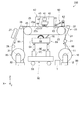
図1は、実施形態に係る印刷装置の概略全体構成を示す模式図である。まず、本実施形態に係る印刷装置100の概略構成について図1を参照して説明する。なお、本実施形態では、印刷媒体95に画像などを形成することで印刷媒体95に捺染を行うインクジェット式の印刷装置100を例に上げて説明する。
(Embodiment)
<Schematic configuration of printing device>
FIG. 1 is a schematic diagram illustrating a schematic overall configuration of a printing apparatus according to an embodiment. First, a schematic configuration of the
図1に示すように、印刷装置100は、媒体供給部10、媒体搬送部20、媒体回収部30、印刷部40、乾燥ユニット27、洗浄ユニット50、及び媒体密着部60などを備えている。そして、これらの各部を制御する制御部1を有している。印刷装置100の各部は、フレーム部90に取り付けられている。
As illustrated in FIG. 1, the
媒体供給部10は、画像を形成させる印刷媒体95を印刷部40側に供給するものである。印刷媒体95としては、例えば、綿、ウール、化学繊維、混紡などの布帛が用いられる。媒体供給部10は、供給軸部11及び軸受部12を有している。供給軸部11は、円筒状又は円柱状に形成されており、円周方向に回転可能に設けられている。供給軸部11には、帯状の印刷媒体95がロール状に巻かれている。供給軸部11は、軸受部12に対して着脱可能に取り付けられている。これにより、予め供給軸部11に巻かれた状態の印刷媒体95は、供給軸部11と共に軸受部12に取り付けできるようになっている。
The
軸受部12は、供給軸部11の軸方向の両端を回転可能に支持している。媒体供給部10は、供給軸部11を回転駆動させる回転駆動部(図示せず)を有している。回転駆動部は、印刷媒体95が送り出される方向に供給軸部11を回転させる。回転駆動部の動作は、制御部1によって制御される。
The bearing
媒体搬送部20は、印刷媒体95を媒体供給部10から媒体回収部30まで搬送するものである。媒体搬送部20は、搬送ローラー21、搬送ローラー22、無端ベルト23、ベルト回転ローラー24、ベルト駆動ローラー25、搬送ローラー26、及び搬送ローラー28を備えている。搬送ローラー21,22は、印刷媒体95を媒体供給部10から無端ベルト23まで中継する。
The
無端ベルト23、ベルト回転ローラー24及びベルト駆動ローラー25は、印刷部40において印刷媒体95を搬送方向(+X軸方向)に搬送させる媒体搬送手段である。詳しくは、無端ベルト23は、帯状のベルトの両端部が接続されて無端状に形成されており、ベルト回転ローラー24及びベルト駆動ローラー25に掛けられている。無端ベルト23は、ベルト回転ローラー24とベルト駆動ローラー25との間の部分が床面99に対して平行になるように、所定の張力が作用した状態で保持されている。無端ベルト23の表面(支持面)23aには、印刷媒体95を粘着させる粘着層29が設けられている。無端ベルト23は、搬送ローラー22から供給され、後述する媒体密着部60で粘着層29に密着された印刷媒体95を支持(保持)している。これにより、伸縮性のある布帛などを印刷媒体95として扱うことができる。
The
ベルト回転ローラー24及びベルト駆動ローラー25は、無端ベルト23の内周面23bを支持する。なお、ベルト回転ローラー24とベルト駆動ローラー25との間に、無端ベルト23を支持する支持部が設けられた構成であってもよい。
The
ベルト駆動ローラー25は、ベルト駆動ローラー25を回転駆動させるモーター(図示せず)を有している。ベルト駆動ローラー25が回転駆動されるとベルト駆動ローラー25の回転に伴って無端ベルト23が回転し、無端ベルト23の回転によりベルト回転ローラー24が回転する。無端ベルト23の回転により、無端ベルト23に支持された印刷媒体95が所定の搬送方向(+X軸方向)に搬送され、後述する印刷部40で印刷媒体95に画像が形成される。本実施形態では、無端ベルト23の表面23aが印刷部40と対向する側(+Z軸側)において印刷媒体95が支持され、印刷媒体95が無端ベルト23と共にベルト回転ローラー24側からベルト駆動ローラー25側に搬送される。また、無端ベルト23の表面23aが洗浄ユニット50と対向する側(−Z軸側)においては、無端ベルト23のみがベルト駆動ローラー25側からベルト回転ローラー24側に移動する。
The
搬送ローラー26は、画像の形成された印刷媒体95を無端ベルト23の粘着層29から剥離させる。搬送ローラー26,28は、印刷媒体95を無端ベルト23から媒体回収部30まで中継する。
The
媒体回収部30は、媒体搬送部20によって搬送された印刷媒体95を回収する。媒体回収部30は、巻取り軸部31及び軸受部32を有している。巻取り軸部31は、円筒状又は円柱状に形成されており、円周方向に回転可能に設けられている。巻取り軸部31には、帯状の印刷媒体95がロール状に巻き取られている。巻取り軸部31は、軸受部32に対して着脱可能に取り付けられている。これにより、巻取り軸部31に巻き取られた状態の印刷媒体95は、巻取り軸部31と共に取り外せるようになっている。
The
軸受部32は、巻取り軸部31の軸線方向の両端を回転可能に支持している。媒体回収部30は、巻取り軸部31を回転駆動させる回転駆動部(図示せず)を有している。回転駆動部は、印刷媒体95が巻き取られる方向に巻取り軸部31を回転させる。回転駆動部の動作は、制御部1によって制御される。
The bearing
乾燥ユニット27は、印刷媒体95上に吐出された液体(液滴)を乾燥するものであり、搬送ローラー26と搬送ローラー28との間に設けられている。乾燥ユニット27には、例えば、IRヒーターを含み、IRヒーターを駆動させることにより印刷媒体95上に吐出された液体を短時間で乾燥させることができる。これにより、画像などの形成された帯状の印刷媒体95を巻取り軸部31に巻き取ることができる。
The drying
媒体密着部60は、印刷媒体95を無端ベルト23に密着させるものである。媒体密着部60は、印刷媒体95の搬送方向に対して印刷部40より上流側(−X軸側)に設けられている。媒体密着部60は、押圧ローラー61、押圧ローラー駆動部62及びローラー支持部63を有している。押圧ローラー61は、円筒状又は円柱状に形成されており、円周方向に回転可能に設けられている。押圧ローラー61は、搬送方向に沿った方向に回転するように、軸線方向が搬送方向と交差するように配置されている。ローラー支持部63は、無端ベルト23を挟んで押圧ローラー61と対向する無端ベルト23の内周面23b側に設けられている。
The
押圧ローラー駆動部62は、押圧ローラー61を鉛直方向の下方側(−Z軸側)に押圧しながら搬送方向(+X軸方向)、及び搬送方向と逆向きの方向(−X軸方向)に押圧ローラー61を移動させる。搬送ローラー22から搬送され、無端ベルト23に重ね合された印刷媒体95は、押圧ローラー61とローラー支持部63との間で無端ベルト23に押し当てられる。これにより、無端ベルト23の表面23aに設けられている粘着層29に印刷媒体95を確実に粘着させることができ、無端ベルト23上での印刷媒体95の浮きの発生を防止することができる。
The pressing
洗浄ユニット50は、無端ベルト23の表面23aを洗浄するためのものである。洗浄ユニット50は、洗浄部51、押圧部52及び移動部53を有している。移動部53は、床面99に沿って洗浄ユニット50を一体的に移動させて所定の位置に固定させる。洗浄ユニット50は、X軸方向においてベルト回転ローラー24とベルト駆動ローラー25の間に配置されている。
The
押圧部52は、例えば、エアーシリンダー56とボールブッシュ57とで構成された昇降装置であり、その上部に備えられている洗浄部51を無端ベルト23の表面23aに当接させるものである。洗浄部51は、ベルト回転ローラー24とベルト駆動ローラー25との間で所定の張力が作用した状態で掛けられている無端ベルト23の表面(支持面)23aを下方(−Z軸方向)から洗浄する。
The
洗浄部51は、洗浄槽54、洗浄ローラー58及びブレード55を有している。洗浄槽54は、無端ベルト23の表面23aに付着したインクや異物の洗浄に用いる洗浄液を貯留する槽であり、洗浄ローラー58及びブレード55は洗浄槽54の内側に設けられている。洗浄液としては、例えば、水や水溶性溶剤(アルコール水溶液など)を用いることができ、必要に応じて界面活性剤や消泡剤を添加してもよい。
The
洗浄ローラー58が回転すると、洗浄液が無端ベルト23の表面23aに供給されると共に、洗浄ローラー58と無端ベルト23とが摺動する。これにより、無端ベルト23に付着したインクや印刷媒体95としての布帛の繊維などが洗浄ローラー58で取り除かれる。
When the cleaning
ブレード55は、例えば、シリコンゴムなどの可撓性の材料で形成することができる。ブレード55は、無端ベルト23の搬送方向において洗浄ローラー58よりも下流側に設けられている。無端ベルト23とブレード55とが摺動することにより、無端ベルト23の表面23aに残っている洗浄液が除去される。
The
印刷部40は、印刷媒体95に向けてインクを液滴として吐出するインクジェット方式の吐出ヘッド42と、吐出ヘッド42が搭載されたキャリッジ43を移動させるキャリッジ移動部41などを有している。印刷部40は、無端ベルト23の配置位置に対して上方(+Z軸側)に配置されている。吐出ヘッド42には、複数のノズル列45が形成されているノズルプレート44が備えられている。例えば、ノズルプレート44には、4つのノズル列45が形成され、ノズル列45毎に異なる色のインク(例えば、シアン:C、マゼンタ:M、イエロー:Y、ブラック:K)が吐出されるようになっている。ノズルプレート44は、無端ベルト23によって搬送される印刷媒体95と対向している。
The
キャリッジ移動部41は、印刷媒体95の搬送方向と交差する方向(印刷媒体95の幅方向(Y軸方向))に吐出ヘッド42を移動させる。キャリッジ43は、Y軸方向に沿って配置されたガイドレール(図示せず)に支持され、キャリッジ移動部41によって±Y軸方向に往復移動可能に構成されている。キャリッジ移動部41の機構としては、例えば、ボールねじとボールナットとを組み合わせた機構や、リニアガイド機構などを採用することができる。
The
さらに、キャリッジ移動部41には、キャリッジ43をY軸方向に沿って移動させるための動力源として、モーター(図示せず)が設けられている。制御部1の制御によりモーターが駆動されると、吐出ヘッド42は、キャリッジ43と共にY軸方向に沿って往復移動する。なお、本実施形態では、吐出ヘッド42として、可動のキャリッジに搭載され印刷媒体95の幅方向(±Y軸方向)に移動しながらインクを吐出するシリアルヘッド式を例示したが、印刷媒体95の幅方向(Y軸方向)に延在し固定して配列されたラインヘッド式であってもよい。
Furthermore, the
<電気的構成>
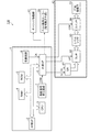
図2は、印刷装置の電気的な構成を示す電気ブロック図である。次に、印刷装置100の電気的構成について図2を参照して説明する。
<Electrical configuration>
FIG. 2 is an electrical block diagram illustrating an electrical configuration of the printing apparatus. Next, the electrical configuration of the
印刷装置100は、制御部1を備えている。制御部1は印刷装置100の制御を行うための制御ユニットである。制御部1は、外部インターフェイス(外部I/F)2と、RAM(Random Access Memory)4及びROM(Read Only Memory)5などの記憶素子と、CPU(CENTRAL PROCESSING UNIT)3と、駆動信号発生回路7と、発振回路8と、内部インターフェイス(内部I/F)6とを備えている。
The
外部I/F2は、コンピューターなどの画像を取り扱う外部装置(図示せず)と印刷装置100との間でデータの送受信を行うためのものである。RAM4は各種データ等を記憶し、ROM5は各種データ処理のための制御ルーチン等を記憶するものである。
CPU3は、ROM5に記憶された動作プログラム等に従って印刷装置100の各部を制御するものである。また、CPU3は、外部I/F2を介して外部装置から入力された印刷データを、吐出ヘッド42において液滴(インク)の吐出に用いられる吐出データに変換する。
The external I /
The
駆動信号発生回路7は、CPU3によって定められた波形形状の駆動信号COMを発生する回路である。発振回路8は、印刷装置100の制御信号CKを生成するためのタイミングデバイスである。内部I/F6は、印刷データをドット毎に展開(データ変換)することで得られた吐出データや駆動信号COM等をキャリッジ移動部41、ベルト駆動ローラー25、吐出ヘッド42に出力するためのものである。
The drive
また、吐出ヘッド42は、記録データSIがセットされるシフトレジスター(SR)91と、シフトレジスター91にセットされた記録データSIをラッチ信号(LAT)に基づいてラッチするラッチ回路92と、電圧増幅器として機能するレベルシフター93と、圧電振動子72と、圧電振動子72に対する駆動信号COMの供給を制御するスイッチ回路94とを備えている。
The
図3は、吐出ヘッドの構成を示す断面図である。次に、吐出ヘッド42の構造について説明する。
図3に示すように、吐出ヘッド42は、複数の圧電振動子72、固定板73、及び、フレキシブルケーブル74等をユニット化した振動子ユニット70と、この振動子ユニット70を収納可能なケース71と、ケース71の先端面に接合された流路ユニット80とを備えている。
FIG. 3 is a cross-sectional view showing the configuration of the ejection head. Next, the structure of the
As shown in FIG. 3, the
ケース71は、先端と後端が共に開放された収納空部75を形成した合成樹脂製のブロック状部材であり、収納空部75内には振動子ユニット70が収納固定されている。
The
圧電振動子72は、縦方向に細長い櫛歯状に形成されている。この圧電振動子72は、圧電体と内部電極とを交互に積層して構成された積層型の圧電振動子であって、積層方向に直交する縦方向に伸縮可能な縦振動モードの圧電振動子である。そして、各圧電振動子72の先端面が、流路ユニット80の島部76に接合されている。
なお、この圧電振動子72はコンデンサーと同じように振る舞う。即ち、信号の供給が停止された場合において、圧電振動子72の電位は、停止直前の電位で保持される。
The
The
流路ユニット80は、流路形成基板83を間に挟んでノズルプレート44を流路形成基板83の一方の面側に配置し、弾性板84をノズルプレート44とは反対側となる他方の面側に配置して積層することで構成されている。
In the
ノズルプレート44は、複数(例えば、180個)のノズル46を副走査方向(X軸方向)に沿って開設した薄手の金属製板材(例えば、ステンレス板)によって構成してある。流路形成基板83は、共通インク室86、インク供給口87、圧力室88、及び、ノズル連通口89からなる一連のインク流路が形成された板状部材である。本実施形態では、この流路形成基板83を、シリコンウェハーのエッチング処理によって作製している。弾性板84は、ステンレス製の支持板82上に樹脂フィルム81をラミネート加工した二重構造の複合板材であり、圧力室88に対応した部分の支持板82を環状に除去して島部76を形成している。
The
この吐出ヘッド42では、共通インク室86から圧力室88を通ってノズル46に至る一連のインク流路がノズル46毎に形成される。そして、圧電振動子72を充電したり放電したりすることで圧電振動子72が変形する。即ち、この縦振動モードの圧電振動子72は、充電によって振動子長手方向に収縮し、放電によって振動子長手方向に伸長する。従って、充電によって電位を上昇させると、島部76が圧電振動子72側に引っ張られ、島部76周辺の樹脂フィルム81が変形して圧力室88が膨張する。また、放電によって電位を下降させると、圧力室88が収縮する。
In the
このように、電位に応じて圧力室88の容積が制御できるので、圧力室88内のインクに圧力変動を生じさせることができ、ノズル46からインク滴を吐出させることができる。例えば、定常容量(基準容積)の圧力室88を一旦膨張させた後に急激に収縮させることで、インクを液滴に吐出させることができる。
As described above, since the volume of the
なお、本実施形態では、縦振動型の圧電振動子72を用いた構成を例示したが、これに限定するものではない。例えば、下電極と圧電体層と上電極とを積層形成した撓み変形型の圧電振動子を用いてもよい。また、圧力室88を膨張、収縮させる手段として、発熱体を用いてノズル内に泡を発生させ、その泡によってインクを液滴として吐出させる構成を有する吐出ヘッドであってもよい。
In the present embodiment, the configuration using the longitudinal vibration type
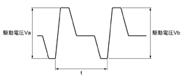
図4は、2回連続して液滴を吐出させる場合の駆動波形を示す図である。
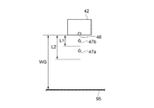
図5及び図6は、ノズルから液滴を吐出させた時の側面図である。次に、ノズルから吐出させる液滴について図4から図6を参照して説明する。
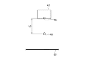
本実施形態の印刷装置100は、制御部1から出力され、吐出ヘッド42の圧電振動子72に印加する駆動波形に基づいて、ノズル46から印刷媒体95の所定位置(所定画素)に複数の液滴47を吐出させる。制御部1が図4に示す駆動波形を生成して圧電振動子72に印加すると、圧電振動子72が駆動電圧Vaの変位に応じて伸縮しノズル46から液滴47aが吐出される。そして、時間t(以下、吐出間隔tともいう)の経過後、圧電振動子72が駆動電圧Vbの変位に応じてノズル46から液滴47bが吐出される。図5は、2つの液滴47a,47bが吐出された状態を示している。
FIG. 4 is a diagram illustrating a driving waveform when droplets are ejected twice in succession.
5 and 6 are side views when droplets are ejected from the nozzle. Next, droplets discharged from the nozzle will be described with reference to FIGS.
The
また、制御部1は、複数の液滴47をノズル46から印刷媒体95までの間の距離WG(以下、「ギャップWG」という)の1/2以下の距離L3で合体させることが可能な駆動波形を出力するので、距離L3までに、先行して吐出された液滴47a(以下、先行液滴47aともいう)に後から吐出された液滴47b(以下、後続液滴47bともいう)が追いつき、合体された液滴48が所定画素に着弾する。図6は、液滴47a,47bが合体された液滴48の状態を示している。
Further, the
ノズル46から液滴47を吐出させると、液滴47が尾引きを伴って飛行し、液滴47から分離した質量の軽い液体が、ミストとなって滞留することが知られている。布帛などの印刷媒体95に捺染を行う印刷装置100では、ギャップWGを、例えば2mm以上に広くして印刷を行う必要があるため、複数の液滴47が単独で飛行する距離が長くなると、各々の液滴47からミストが発生し、吐出ヘッド42と印刷媒体95との間に残留するミストの量が増えてしまう。そして、ミストが吐出ヘッド42のノズルプレート44に付着して液滴47の吐出不良を起こしたり、印刷媒体95に付着して印刷媒体95が汚染されたりして、印刷された画像などの印刷品質が低下していた。
It is known that when the liquid droplet 47 is ejected from the
図7は、液滴の合体位置と印刷媒体の汚れとの関係を示す表である。
本願の発明者らは、ノズル46から吐出させた液滴47を合体させる距離L3と、印刷媒体95がミストよって汚染される状態(汚れ)とを調べた結果、図7に示すように、複数の液滴47が合体するまでの距離L3をギャップWGの1/2以下にさせることで、ミストによる印刷媒体95の汚染が大幅に改善されることを見出した。また、ノズルプレート44に付着するミストの量も減少することが確認された。
FIG. 7 is a table showing the relationship between the droplet coalescing position and the stain on the print medium.
As a result of examining the distance L3 at which the droplets 47 ejected from the
図8は、駆動電圧と吐出された液滴の速度との関係を示すグラフである。図8の横軸は、液滴47を吐出させる際に圧電振動子72に印加される電圧を所定の電圧で基準化した基準化電圧で表している。図8の縦軸は、ノズル46から吐出された液滴47の速度を表している。
図9は、吐出された液滴の速度変化を示すグラフである。図9の横軸は、ノズル46(ノズルプレート44)からの距離を示している。図9の縦軸は、ノズル46から吐出された液滴47の速度を表している。なお、図8及び図9は、先に吐出された液滴47aの速度を実線で示し、後から吐出された液滴47bの速度を1点鎖線で示している。
FIG. 8 is a graph showing the relationship between the drive voltage and the velocity of the ejected droplets. The horizontal axis of FIG. 8 represents a standardized voltage obtained by standardizing a voltage applied to the
FIG. 9 is a graph showing a change in velocity of the discharged droplet. The horizontal axis in FIG. 9 indicates the distance from the nozzle 46 (nozzle plate 44). The vertical axis in FIG. 9 represents the velocity of the droplet 47 ejected from the
本実施形態の印刷装置100及びその吐出方法は、制御部1から出力される駆動波形に基づいて、先行して吐出させる液滴47aの駆動電圧に対して95%以上130%以下の駆動電圧で後続液滴47bを吐出させる。図8に示すように、同じ駆動電圧で液滴を連続して吐出させた場合、後から吐出された液滴(後続液滴)47bの速度は、先行して吐出された液滴(先行液滴)47aの速度より早くなる。移動中の物体は、進行方向の前面に空気抵抗を受けるが、物体の後方では気圧が低下した状態(スリップストリーム)となる。後続液滴47bは、先行液滴47aのスリップストリームによって進行方向の全面で受ける空気抵抗が低下し、先行液滴47aより早い速度で移動することが可能になる。換言すると、後続液滴47bは、先行液滴47aより低い駆動電圧で吐出されても先行液滴47aに追いつき合体することが可能である。例えば、基準化電圧0.95の駆動電圧で吐出された後続液滴47bの速度は、基準化電圧1.0の駆動電圧で吐出された先行液滴47aの速度と、略同じであり、基準化電圧0.95から1.0の駆動電圧で吐出された後続液滴47bは、液滴47aの速度より早くなっている。
The
図9は、ノズル46からの距離L1(図5参照)のL1地点、及びノズル46からの距離L2(図5参照)のL2地点における液滴47a,47bの速度を表している。先行液滴47a、及び後続液滴47bともに、移動距離に比例して速度が低下する。しかし、後続液滴47bは、先行液滴47aのスリップストリームによって、先行液滴47aよりも速度低下の比率が小さくなるので、後続液滴47bの駆動電圧が先行液滴47aの駆動電圧より低くても先行液滴47aに追いつき合体することが可能になる。例えば、略同一の速度で吐出された先行液滴47a及び後続液滴47bは、L2地点において先行液滴47aより後続液滴47bの方の速度が略0.5m/s早くなっている。
FIG. 9 shows the velocities of the
例えば、ギャップWGを2mm以上、吐出間隔(時間t)を17μs、とし、先行液滴47aの平均速度を5m/s、先行液滴47aと後続液滴47bとの平均速度差を0.5m/sとした時、液滴47a,47bは、距離L3=1mm以下で合体した液滴48になる。したがって、先行して吐出させた液滴(先行液滴47a)の駆動電圧に対して95%以上の駆動電圧で後続液滴47bを吐出させることで、液滴47a,47bはギャップWGの1/2以下の距離L3で合体される。なお、液滴47を吐出させる駆動電圧を必要以上に高くすると、液滴47を吐出した際に生じるミストの量が増加するので、後続液滴47bは、先行液滴47aの130%以下の駆動電圧で吐出させることが好ましい。また、ギャップWGの1/2以下の距離L3で合体された液滴48は、質量の増加により飛行速度の低下が抑制されるので、液滴を着弾させる位置精度が向上される。
For example, the gap WG is 2 mm or more, the discharge interval (time t) is 17 μs, the average velocity of the preceding
図10は、4回連続して液滴を吐出させる場合の駆動波形を示す図である。図11は、液滴を吐出させる駆動波形テーブルの一例を示す図である。
次に、4回連続して液滴を吐出させる場合の駆動波形を例示する。
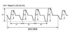
制御部1が図10に示す駆動波形を生成して圧電振動子72に印加されると、圧電振動子72が駆動電圧V1の変位に応じて伸縮しノズル46から第1液滴が吐出される。そして、時間t1後に駆動電圧V2の変位に応じて第2液滴が吐出され、さらに時間t2後に駆動電圧V3の変位に応じて第3液滴が吐出され、さらに時間t3後に駆動電圧V4の変位に応じて第4液滴が吐出される。第1から第4液滴は、ギャップWGの1/2の距離までに合体され、所定画素に着弾する。なお、第1から第4液滴を吐出させるために出力される最大の駆動電圧を最大駆動電圧VHとする。図10の例では、第4液滴を吐出させる駆動電圧V4が、駆動波形の波形1周期の最大駆動電圧VHになっている。また、波形1周期は略80μs、第1から第4液滴の吐出間隔(時間t1,t2,t3)は20μs以下に設定されている。
FIG. 10 is a diagram showing a driving waveform when droplets are ejected four times in succession. FIG. 11 is a diagram illustrating an example of a drive waveform table for discharging droplets.
Next, drive waveforms when droplets are ejected four times in succession will be exemplified.
When the
本実施形態の印刷装置100は、インクの種類、及び周囲温度の条件に応じて液滴を吐出させるための駆動波形テーブルがRAM4に格納され、印刷時に入力されるインク種類と周囲温度に基づいて駆動波形テーブルを参照し、駆動波形を生成する。図11に示す駆動波形テーブルには、4つの液滴を吐出させて所定画素に着弾させる場合の駆動電圧V1〜V4が最大駆動電圧HVに対する割合(「VHに対する割合」の列参照)で示されている。また、図11では、参考に先行液滴に対する後続液滴の電圧比(「先行液滴に対する電圧比」の列参照)を記している。
In the
最初の液滴は、制御部1から出力される駆動波形に基づいて、最大駆動電圧VHに対して70%以上の駆動電圧V1で吐出される。図11の「VHに対する割合」に示すように、第1液滴を吐出させる駆動電圧V1は、最大駆動電圧VHの70%以上に設定されている。これは、後続液滴と早く合体させるために第1液滴を吐出させる駆動電圧を低くしすぎると、ノズル46付近に付着したミストや、増粘したインクなどによる影響を受けやすくなり、液滴の吐出が不安定になるためである。本実施形態の印刷装置100は、インク種類と周囲温度との全ての組合せ条件において、第1液滴を吐出させる駆動電圧V1が最大駆動電圧VHの70%以上に設定されているので、間欠能力が確保され、増粘による吐出不良を低減させることができる。
The first droplet is ejected at a driving voltage V1 of 70% or more with respect to the maximum driving voltage VH based on the driving waveform output from the
また、図11の「先行液滴に対する電圧比」に示すように、第2から第4液滴(後続液滴)を吐出させる駆動電圧V2〜V4は、直前に吐出させた第1から第3液滴(先行液滴)の駆動電圧V1〜V3に対して95%以上130%以下(図11の例では120%以下)に設定されている。また、第3、第4液滴は、上述した先行液滴から受けるスリップストリームの影響が大きくなるので、第1から第4液滴は、ギャップWGの1/2以下の距離L3で合体され所定画素に着弾させることができる。各液滴が単独で飛行する距離が短くなるので、各々の液滴から発生するミストが減少し、吐出ヘッド42と印刷媒体95との間に残留するミストの量も減少する。これにより、吐出ヘッド42のノズルプレート44にミストが付着することにより生じる吐出不良を低減させ、液滴の吐出を安定させることができる。また、相対的に印刷媒体95に近いエリアに浮遊するミストが少なくなり、ミストによる印刷媒体95の汚染が大幅に改善される。これらにより、印刷媒体95に印刷された画像などの印刷品質が向上される。
Further, as shown in “Voltage ratio with respect to preceding droplet” in FIG. 11, the driving voltages V2 to V4 for discharging the second to fourth droplets (following droplets) are the first to third discharged immediately before. It is set to 95% or more and 130% or less (120% or less in the example of FIG. 11) with respect to the driving voltages V1 to V3 of the droplets (preceding droplets). In addition, since the third and fourth droplets are greatly affected by the slip stream received from the preceding droplets, the first to fourth droplets are combined at a distance L3 that is ½ or less of the gap WG and are predetermined. The pixel can be landed. Since the distance that each droplet travels alone is shortened, the mist generated from each droplet is reduced, and the amount of mist remaining between the
なお、図11では、4つの液滴を吐出させる駆動波形テーブルを例示したが、本実施形態の印刷装置100は、1つ〜4つの液滴を吐出させる駆動波形テーブルを有している。
また、本実施形態では、捺染用のインクジェット式の印刷装置100を例示したが、本発明はインクジェット式の印刷装置全般に適用することができる。
In FIG. 11, the drive waveform table for ejecting four droplets is illustrated, but the
Further, in the present embodiment, the
以上述べたように、本実施形態に係る印刷装置100によれば、以下の効果を得ることができる。
印刷装置100は、複数の液滴47をノズル46から印刷媒体95までの距離(ギャップWG)の1/2以下の距離L3で合体させることが可能な駆動波形を出力する制御部1を備えている。複数の液滴47をギャップWGの1/2以下の距離L3で合体されることで、複数の液滴47が単独で飛行する距離が短縮され、各々の液滴47から生じるミストの量が減少し、吐出ヘッド42と印刷媒体95との間に残留するミストの量も減少する。これにより、吐出ヘッド42のノズルプレート44にミストが付着することにより生じる吐出不良を低減させ、液滴の吐出を安定させることができる。また、相対的に印刷媒体95に近いエリアに浮遊するミストが少なくなる。これにより、印刷媒体95がミストで汚染されることが抑制されるので、印刷媒体95に印刷される画像などの品質が向上する。また、ギャップWGの1/2以下の距離L3で合体させた液滴48は、質量の増加により飛行速度の低下が抑制されるので、液滴を着弾させる位置精度が向上される。したがって、印刷品質を向上させた印刷装置100を提供することができる。
As described above, according to the
The
後続液滴47bは、先行液滴47aの駆動電圧に対して95%以上の駆動電圧で吐出される。これにより、ギャップWGの1/2以下の距離L3で後続液滴47bを先行液滴47aに追い付かせ合体させることができる。また、後続液滴47bは、先行液滴47aの130%以下の駆動電圧で吐出されるので、ノズル46から液滴が吐出する際に生じるミストの量を軽減させることができる。
最初に吐出される先行液滴(第1液滴)は、最大駆動電圧VHの70%以上の駆動電圧で吐出されるので、ノズル46付近に付着したミストや、増粘したインクなどによる影響が軽減され、液滴の吐出を安定させることができる。
The
Since the first droplet (first droplet) ejected first is ejected at a driving voltage of 70% or more of the maximum driving voltage VH, it is affected by mist adhering to the vicinity of the
印刷装置100において、印刷媒体95の所定位置に複数の液滴47を吐出させる吐出方法は、先行液滴47aの駆動電圧に対して95%以上130%以下の駆動電圧で後続液滴47bを吐出させる。これにより、ノズル46から吐出された複数の液滴47を、ノズル46から印刷媒体95までの距離の1/2以下の距離L3で合体させることができるので、複数の液滴47が単独で飛行する距離が短縮され、各々の液滴47から生じるミストの量が減少し、吐出ヘッド42と印刷媒体95との間に残留するミストの量も減少する。これにより、吐出ヘッド42のノズルプレート44にミストが付着することにより生じる吐出不良を低減させ、液滴の吐出を安定させることができる。また、相対的に印刷媒体95に近いエリアに浮遊するミストが少なくなる。これにより、印刷媒体95がミストで汚染されることが抑制されるので、印刷媒体95に印刷される画像などの品質が向上する。また、ギャップWGの1/2以下の距離L3で合体させた液滴48は、質量の増加により飛行速度の低下が抑制されるので、液滴を着弾させる位置精度が向上される。したがって、印刷品質を向上させた吐出方法を提供することができる。
In the
1…制御部、2…外部I/F、3…CPU、4…RAM、5…ROM、6…内部I/F、7…駆動信号発生回路、8…発振回路、10…媒体供給部、20…媒体搬送部、30…媒体回収部、40…印刷部、42…吐出ヘッド、43…キャリッジ、44…ノズルプレート、46…ノズル、47,47a,47b,48…液滴、50…洗浄ユニット、60…媒体密着部、70…振動子ユニット、72…圧電振動子、91…シフトレジスター、92…ラッチ回路、93…レベルシフター、94…スイッチ回路、95…印刷媒体、100…印刷装置。
DESCRIPTION OF
Claims (4)
前記複数の液滴を前記ノズルから前記印刷媒体までの距離の1/2以下の距離で合体させることが可能な駆動波形を前記吐出ヘッドに出力する制御部と、
を備えていること、を特徴とする印刷装置。 An ejection head for ejecting a plurality of droplets from a nozzle to a predetermined position of a print medium;
A controller that outputs to the ejection head a drive waveform capable of combining the plurality of liquid droplets at a distance of ½ or less of the distance from the nozzle to the print medium;
A printing apparatus.
前記複数の液滴を前記ノズルから前記印刷媒体までの距離の1/2以下の距離で合体させることが可能な駆動波形を前記吐出ヘッドに出力する制御部と、
を備えた印刷装置の吐出方法であって、
前記駆動波形における、先行して吐出させる液滴の駆動電圧に対して95%以上130%以下の駆動電圧で後続の液滴を吐出すること、を特徴とする吐出方法。 An ejection head for ejecting a plurality of droplets from a nozzle to a predetermined position of a print medium;
A controller that outputs to the ejection head a drive waveform capable of combining the plurality of liquid droplets at a distance of ½ or less of the distance from the nozzle to the print medium;
A discharge method for a printing apparatus comprising:
A discharging method comprising discharging a subsequent droplet at a driving voltage of 95% or more and 130% or less with respect to a driving voltage of a droplet to be discharged in advance in the driving waveform.
Priority Applications (2)
| Application Number | Priority Date | Filing Date | Title |
|---|---|---|---|
| JP2016023391A JP6699211B2 (en) | 2016-02-10 | 2016-02-10 | Printing device and ejection method |
| CN201710072323.5A CN107053846B (en) | 2016-02-10 | 2017-02-09 | Printing apparatus and ejection method thereof |
Applications Claiming Priority (1)
| Application Number | Priority Date | Filing Date | Title |
|---|---|---|---|
| JP2016023391A JP6699211B2 (en) | 2016-02-10 | 2016-02-10 | Printing device and ejection method |
Publications (2)
| Publication Number | Publication Date |
|---|---|
| JP2017140761A true JP2017140761A (en) | 2017-08-17 |
| JP6699211B2 JP6699211B2 (en) | 2020-05-27 |
Family
ID=59599010
Family Applications (1)
| Application Number | Title | Priority Date | Filing Date |
|---|---|---|---|
| JP2016023391A Active JP6699211B2 (en) | 2016-02-10 | 2016-02-10 | Printing device and ejection method |
Country Status (2)
| Country | Link |
|---|---|
| JP (1) | JP6699211B2 (en) |
| CN (1) | CN107053846B (en) |
Cited By (2)
| Publication number | Priority date | Publication date | Assignee | Title |
|---|---|---|---|---|
| JP2023129902A (en) * | 2022-03-07 | 2023-09-20 | セイコーエプソン株式会社 | Liquid ejection device and liquid ejection head control method |
| US12491713B2 (en) | 2023-01-12 | 2025-12-09 | Seiko Epson Corporation | Liquid ejecting apparatus |
Citations (4)
| Publication number | Priority date | Publication date | Assignee | Title |
|---|---|---|---|---|
| US4686539A (en) * | 1985-03-11 | 1987-08-11 | Schmidle Lisa M | Multipulsing method for operating an ink jet apparatus for printing at high transport speeds |
| JP2010149335A (en) * | 2008-12-24 | 2010-07-08 | Ricoh Co Ltd | Liquid droplet jetting device, method for jetting liquid droplet, and image forming apparatus |
| JP2011042144A (en) * | 2009-08-24 | 2011-03-03 | Fuji Xerox Co Ltd | Liquid droplet delivering apparatus |
| JP2015178203A (en) * | 2014-03-19 | 2015-10-08 | セイコーエプソン株式会社 | Printer controller and print control method |
Family Cites Families (5)
| Publication number | Priority date | Publication date | Assignee | Title |
|---|---|---|---|---|
| US6488349B1 (en) * | 1999-09-21 | 2002-12-03 | Matsushita Electric Industrial Co., Ltd. | Ink-jet head and ink-jet type recording apparatus |
| US6676238B2 (en) * | 2001-09-28 | 2004-01-13 | Canon Kabushiki Kaisha | Driving method and apparatus for liquid discharge head |
| JP3788759B2 (en) * | 2001-11-02 | 2006-06-21 | リコープリンティングシステムズ株式会社 | Line type recording head for inkjet printer |
| JP2005014431A (en) * | 2003-06-26 | 2005-01-20 | Ricoh Co Ltd | Image forming apparatus |
| JP2011116071A (en) * | 2009-12-07 | 2011-06-16 | Seiko Epson Corp | Liquid injecting device |
-
2016
- 2016-02-10 JP JP2016023391A patent/JP6699211B2/en active Active
-
2017
- 2017-02-09 CN CN201710072323.5A patent/CN107053846B/en active Active
Patent Citations (4)
| Publication number | Priority date | Publication date | Assignee | Title |
|---|---|---|---|---|
| US4686539A (en) * | 1985-03-11 | 1987-08-11 | Schmidle Lisa M | Multipulsing method for operating an ink jet apparatus for printing at high transport speeds |
| JP2010149335A (en) * | 2008-12-24 | 2010-07-08 | Ricoh Co Ltd | Liquid droplet jetting device, method for jetting liquid droplet, and image forming apparatus |
| JP2011042144A (en) * | 2009-08-24 | 2011-03-03 | Fuji Xerox Co Ltd | Liquid droplet delivering apparatus |
| JP2015178203A (en) * | 2014-03-19 | 2015-10-08 | セイコーエプソン株式会社 | Printer controller and print control method |
Cited By (3)
| Publication number | Priority date | Publication date | Assignee | Title |
|---|---|---|---|---|
| JP2023129902A (en) * | 2022-03-07 | 2023-09-20 | セイコーエプソン株式会社 | Liquid ejection device and liquid ejection head control method |
| US12296583B2 (en) | 2022-03-07 | 2025-05-13 | Seiko Epson Corporation | Liquid ejecting apparatus and method for controlling liquid ejecting head |
| US12491713B2 (en) | 2023-01-12 | 2025-12-09 | Seiko Epson Corporation | Liquid ejecting apparatus |
Also Published As
| Publication number | Publication date |
|---|---|
| JP6699211B2 (en) | 2020-05-27 |
| CN107053846A (en) | 2017-08-18 |
| CN107053846B (en) | 2020-06-09 |
Similar Documents
| Publication | Publication Date | Title |
|---|---|---|
| CN102729623B (en) | Liquid ejecting apparatus and method of controlling the same | |
| JP2013056529A (en) | Inkjet recording method and inkjet recording apparatus | |
| CN102233723A (en) | Liquid ejecting apparatus and control method of liquid ejecting apparatus | |
| CN102233724A (en) | Liquid ejecting apparatus and control method of liquid ejecting apparatus | |
| JP2017065249A (en) | Liquid discharge head, liquid discharge unit, and liquid discharge device | |
| JP2006027124A (en) | Image forming device | |
| JP2016040083A (en) | Liquid spray device and liquid spray method | |
| JP2008080740A (en) | Driver of droplet discharge head, driving method, data creation program for driving, and droplet discharge apparatus | |
| JP2012236300A (en) | Fluid discharging device, method and program for inspecting nozzle | |
| JP6699211B2 (en) | Printing device and ejection method | |
| JP6693091B2 (en) | Printer | |
| CN109720109B (en) | Control method of liquid ejection device | |
| JP2018030347A (en) | Device for discharging liquid | |
| CN107303755A (en) | Printing equipment, printing process | |
| JP2009018427A (en) | Liquid ejecting apparatus and method for cleaning liquid ejection head in liquid ejecting apparatus | |
| JP2013018252A (en) | Droplet ejection head, and image forming apparatus | |
| JP6701768B2 (en) | Printing device and printing method | |
| JP4631530B2 (en) | Droplet discharge device | |
| JP2012236339A (en) | Liquid ejecting apparatus | |
| JP2009006685A (en) | Fluid ejection device and fluid ejection method | |
| US20140292916A1 (en) | Head cleaning method and liquid discharging apparatus | |
| JP2016150548A (en) | Method for discharging liquid, device for creating data, program | |
| JP7124414B2 (en) | Printer, controller, and method of printing | |
| JP2020199634A (en) | Carriage and image formation device | |
| JP7073878B2 (en) | Control method of liquid discharge device |
Legal Events
| Date | Code | Title | Description |
|---|---|---|---|
| RD05 | Notification of revocation of power of attorney |
Free format text: JAPANESE INTERMEDIATE CODE: A7425 Effective date: 20180906 |
|
| A621 | Written request for application examination |
Free format text: JAPANESE INTERMEDIATE CODE: A621 Effective date: 20181112 |
|
| RD03 | Notification of appointment of power of attorney |
Free format text: JAPANESE INTERMEDIATE CODE: A7423 Effective date: 20181119 |
|
| A977 | Report on retrieval |
Free format text: JAPANESE INTERMEDIATE CODE: A971007 Effective date: 20190821 |
|
| A131 | Notification of reasons for refusal |
Free format text: JAPANESE INTERMEDIATE CODE: A131 Effective date: 20190827 |
|
| A521 | Request for written amendment filed |
Free format text: JAPANESE INTERMEDIATE CODE: A523 Effective date: 20191017 |
|
| TRDD | Decision of grant or rejection written | ||
| A01 | Written decision to grant a patent or to grant a registration (utility model) |
Free format text: JAPANESE INTERMEDIATE CODE: A01 Effective date: 20200331 |
|
| A61 | First payment of annual fees (during grant procedure) |
Free format text: JAPANESE INTERMEDIATE CODE: A61 Effective date: 20200413 |
|
| R150 | Certificate of patent or registration of utility model |
Ref document number: 6699211 Country of ref document: JP Free format text: JAPANESE INTERMEDIATE CODE: R150 |