JP2017141802A - Rotary compressor and refrigeration cycle equipment - Google Patents
Rotary compressor and refrigeration cycle equipment Download PDFInfo
- Publication number
- JP2017141802A JP2017141802A JP2016025349A JP2016025349A JP2017141802A JP 2017141802 A JP2017141802 A JP 2017141802A JP 2016025349 A JP2016025349 A JP 2016025349A JP 2016025349 A JP2016025349 A JP 2016025349A JP 2017141802 A JP2017141802 A JP 2017141802A
- Authority
- JP
- Japan
- Prior art keywords
- roller
- sub
- peripheral surface
- partition plate
- rotary compressor
- Prior art date
- Legal status (The legal status is an assumption and is not a legal conclusion. Google has not performed a legal analysis and makes no representation as to the accuracy of the status listed.)
- Pending
Links
Images


Landscapes
- Applications Or Details Of Rotary Compressors (AREA)
Abstract
Description
本発明の実施形態は、回転式圧縮機および冷凍サイクル装置に関する。 Embodiments described herein relate generally to a rotary compressor and a refrigeration cycle apparatus.
空気調和装置などの冷凍サイクル装置に使用される回転式圧縮機として、回転軸と、前記回転軸を回転させる電動機部と、前記回転軸の回転によって流体(冷媒)を圧縮する圧縮機構部とを備える回転式圧縮機が知られている。このような回転式圧縮機の圧縮機構部は、例えばそれぞれシリンダ室を形成する複数のシリンダと、回転軸の偏心部に嵌められて前記シリンダ室内で偏心回転するローラと、前記複数のシリンダの間に配置されて前記シリンダ室の一面を規定する仕切板とを有する。 As a rotary compressor used in a refrigeration cycle apparatus such as an air conditioner, a rotary shaft, an electric motor unit that rotates the rotary shaft, and a compression mechanism unit that compresses fluid (refrigerant) by the rotation of the rotary shaft A rotary compressor provided is known. The compression mechanism portion of such a rotary compressor includes, for example, a plurality of cylinders each forming a cylinder chamber, a roller that is fitted in an eccentric portion of a rotation shaft and rotates eccentrically in the cylinder chamber, and a plurality of cylinders. And a partition plate that defines one surface of the cylinder chamber.
ところで、圧縮機構部のローラを、内側ローラと外側ローラとを含む2重構造で形成しようとすると、回転式圧縮機の性能が低下する場合があった。 By the way, when trying to form the roller of the compression mechanism part with a double structure including the inner roller and the outer roller, the performance of the rotary compressor may be deteriorated.
本発明が解決しようとする課題は、性能向上を図ることができる回転式圧縮機および冷凍サイクル装置を提供することである。 The problem to be solved by the present invention is to provide a rotary compressor and a refrigeration cycle apparatus capable of improving performance.
実施形態の回転式圧縮機は、複数のシリンダと、回転軸と、ローラと、ベーンと、仕切板とを備える。前記複数のシリンダは、それぞれシリンダ室を形成する。前記回転軸には、前記シリンダ室内に配置される偏心部が設けられている。前記ローラは、筒状に形成され、前記偏心部に嵌められて前記シリンダ室内で偏心回転する。前記ベーンは、前記ローラの偏心回転に伴って前記シリンダ室内に進退され、前記シリンダ室を吸込室と圧縮室とに仕切る。前記仕切板は、前記複数のシリンダの間に配置されて前記シリンダ室の一面を規定するとともに、前記回転軸が通される開口部が設けられている。前記仕切板の前記開口部の内周面の少なくとも一部は、前記ローラの内周面よりも前記回転軸の径方向の外側に位置する。前記ローラは、同心円状に配置された複数のサブローラにより構成される。前記複数のサブローラのうち最も内側に配置された第1サブローラの外周面は、前記ローラの全周に亘って、前記仕切板の前記開口部の内周面よりも前記径方向の外側に位置する。 The rotary compressor of the embodiment includes a plurality of cylinders, a rotation shaft, a roller, a vane, and a partition plate. Each of the plurality of cylinders forms a cylinder chamber. The rotating shaft is provided with an eccentric portion disposed in the cylinder chamber. The roller is formed in a cylindrical shape, is fitted in the eccentric portion, and rotates eccentrically in the cylinder chamber. The vane is advanced and retracted into the cylinder chamber as the roller rotates eccentrically, and partitions the cylinder chamber into a suction chamber and a compression chamber. The partition plate is disposed between the plurality of cylinders to define one surface of the cylinder chamber, and is provided with an opening through which the rotation shaft is passed. At least a part of the inner peripheral surface of the opening of the partition plate is located on the outer side in the radial direction of the rotating shaft with respect to the inner peripheral surface of the roller. The roller is constituted by a plurality of sub-rollers arranged concentrically. The outer peripheral surface of the first sub-roller arranged on the innermost side among the plurality of sub-rollers is positioned on the outer side in the radial direction over the entire periphery of the roller, with respect to the inner peripheral surface of the opening of the partition plate. .
以下、実施形態の回転式圧縮機および冷凍サイクル装置を、図面を参照して説明する。
始めに、冷凍サイクル装置について簡単に説明する。
図1は、本実施形態の冷凍サイクル装置1を示す概略構成図である。
図1に示すように、冷凍サイクル装置1は、回転式圧縮機2と、回転式圧縮機2に接続された放熱器3と、放熱器3に接続された膨張装置4と、膨張装置4と回転式圧縮機2との間に接続された吸熱器としての蒸発器5とを備えている。
Hereinafter, a rotary compressor and a refrigeration cycle apparatus according to an embodiment will be described with reference to the drawings.
First, the refrigeration cycle apparatus will be briefly described.
FIG. 1 is a schematic configuration diagram showing a refrigeration cycle apparatus 1 of the present embodiment.
As shown in FIG. 1, the refrigeration cycle apparatus 1 includes a rotary compressor 2, a radiator 3 connected to the rotary compressor 2, an expansion device 4 connected to the radiator 3, and an expansion device 4. The
回転式圧縮機2は、いわゆるロータリ式の圧縮機である。回転式圧縮機2は、例えば、内部に取り込まれる低圧の気体冷媒(流体)を圧縮して高温・高圧の気体冷媒にする。なお、回転式圧縮機2の具体的な構成については後述する。 The rotary compressor 2 is a so-called rotary compressor. For example, the rotary compressor 2 compresses a low-pressure gas refrigerant (fluid) taken inside to form a high-temperature / high-pressure gas refrigerant. The specific configuration of the rotary compressor 2 will be described later.
放熱器3は、回転式圧縮機2から送り込まれる高温・高圧の気体冷媒から熱を放熱させ、高温・高圧の気体冷媒を高圧の液体冷媒にする。
膨張装置4は、放熱器3から送り込まれる高圧の液体冷媒の圧力を下げ、高圧の液体冷媒を低温・低圧の液体冷媒にする。
蒸発器5は、膨張装置4から送り込まれる低温・低圧の液体冷媒を気化させ、低温・低圧の液体冷媒を低圧の気体冷媒にする。そして、蒸発器5において、低圧の液体冷媒が気化する際に周囲から気化熱を奪うことで周囲が冷却される。なお、蒸発器5を通過した低圧の気体冷媒は、上述した回転式圧縮機2の内部に取り込まれる。
The radiator 3 radiates heat from the high-temperature and high-pressure gas refrigerant sent from the rotary compressor 2, and converts the high-temperature and high-pressure gas refrigerant into a high-pressure liquid refrigerant.
The expansion device 4 lowers the pressure of the high-pressure liquid refrigerant sent from the radiator 3 so that the high-pressure liquid refrigerant becomes a low-temperature / low-pressure liquid refrigerant.
The
このように、本実施形態の冷凍サイクル装置1では、作動流体である冷媒が気体冷媒と液体冷媒との間で相変化しながら循環し、気体冷媒から液体冷媒に相変化する過程で放熱され、液体冷媒から気体冷媒に相変化する過程で吸熱される。そして、これらの放熱や吸熱を利用して暖房や冷房などが行われる。 Thus, in the refrigeration cycle apparatus 1 of the present embodiment, the refrigerant that is the working fluid circulates while changing phase between the gas refrigerant and the liquid refrigerant, and is radiated in the process of phase change from the gas refrigerant to the liquid refrigerant, Heat is absorbed in the process of phase change from liquid refrigerant to gaseous refrigerant. And heating, cooling, etc. are performed using these heat dissipation and heat absorption.
次に、上述した回転式圧縮機2の具体的な構成について説明する。
本実施形態の回転式圧縮機2は、圧縮機本体11と、アキュムレータ12とを備える。
アキュムレータ12は、いわゆる気液分離器である。アキュムレータ12は、上述した蒸発器5と圧縮機本体11との間に設けられている。アキュムレータ12は、吸い込みパイプ21を通じて圧縮機本体11の複数のシリンダ41,42に接続されている。アキュムレータ12は、蒸発器5で気化された気体冷媒を圧縮機本体11に供給する。
Next, a specific configuration of the rotary compressor 2 described above will be described.
The rotary compressor 2 according to the present embodiment includes a
The
圧縮機本体11は、回転軸31と、回転軸31を回転させる電動機部32と、回転軸31の回転によって気体冷媒を圧縮する圧縮機構部33と、これら回転軸31、電動機部32および圧縮機構部33を収容した円筒状の密閉容器34とを備えている。
The
回転軸31および密閉容器34は、回転軸31の軸線Oに対して同軸状に配置されている。電動機部32は、密閉容器34のなかで、軸線Oに沿う一端側(図1における上側)に配置されている。圧縮機構部33は、密閉容器34のなかで、軸線Oに沿う他端側(図1における下側)に配置されている。なお以下の説明では、軸線Oに沿う方向を回転軸31の軸方向Z、軸線Oに直交するとともに軸線Oから放射状に離れる方向およびその反対方向(軸線Oに近付く方向)を回転軸31の径方向R、軸線Oに対して一定の距離を保ちながら軸線Oの周りを回転する方向を回転軸31の周方向θ(図2参照)と称する。
The rotating
電動機部32は、いわゆるインナーロータ型のDCブラシレスモータである。具体的には、電動機部32は、固定子36と、回転子37とを備える。固定子36は、筒状に形成され、密閉容器34の内壁面に焼嵌めなどによって固定されている。回転子37は、固定子36の内側に配置されている。回転子37には、回転軸31の上部が連結されている。回転子37は、固定子36に設けられたコイルに電流が供給されることで、回転軸31を回転駆動する。
The
次に、圧縮機構部33について説明する。
圧縮機構部33は、複数のシリンダと、仕切板43と、主軸受44と、副軸受45と、複数のローラとを備える。
Next, the
The
複数のシリンダは、第1シリンダ41と、第2シリンダ42とを含む。第1シリンダ41および第2シリンダ42は、互いの間に隙間を空けて軸方向Zに重ねて配置されている。第1シリンダ41および第2シリンダ42の各々は、軸方向Zに開口した筒状に形成されている。これにより、第1シリンダ41には、第1シリンダ室51となる内部空間が形成されている。第2シリンダ42には、第2シリンダ室52となる内部空間が形成されている。第1シリンダ41および第2シリンダ42の各々には、上述した吸い込みパイプ21が個別に接続されている。第1シリンダ室51および第2シリンダ室52には、アキュムレータ12で気液分離された気体冷媒が吸い込みパイプ21を通じて供給される。
The plurality of cylinders includes a
仕切板43は、第1シリンダ41と第2シリンダ42との間に配置され、第1シリンダ41と第2シリンダ42との間に挟まれている。仕切板43は、第1シリンダ41の内部空間に面して、第1シリンダ室51の一面を規定している。同様に、仕切板43は、第2シリンダ42の内部空間に面して、第2シリンダ室52の一面を規定している。また、仕切板43には、軸方向Zに回転軸31が通される開口部55が設けられている。
The
主軸受44は、第1シリンダ41に対して仕切板43とは反対側に位置する。主軸受44は、仕切板43とは反対側から第1シリンダ41の内部空間に面して、第1シリンダ室51の別の一面を規定している。一方で、副軸受45は、第2シリンダ42に対して仕切板43とは反対側に位置する。副軸受45は、仕切板43とは反対側から第2シリンダ42の内部空間に面して、第2シリンダ室52の別の一面を規定している。
The
ここで、上述した回転軸31は、第1シリンダ41,第2シリンダ42、および仕切板43を貫通するとともに、主軸受44と副軸受45とによって回転可能に支持されている。回転軸31には、第1偏心部61と、第2偏心部62とが設けられている。第1偏心部61は、回転軸31のなかで第1シリンダ室51に対応する部分に設けられ、第1シリンダ室51内に配置されている。第2偏心部62は、回転軸31のなかで第2シリンダ室52に対応する部分に設けられ、第2シリンダ室52内に配置されている。第1偏心部61および第2偏心部62の各々は、軸方向Zに沿う円柱状に形成されている。第1偏心部61および第2偏心部62は、軸線Oに対して径方向Rに同一量ずつ偏心している。第1偏心部61および第2偏心部62は、軸方向Zから見た平面視で例えば同形同大に形成されるとともに、周方向θに180°の位相差をもって配置されている。
Here, the rotating
複数のローラは、第1ローラ46と、第2ローラ47とを含む。第1ローラ46および第2ローラ47の各々は、軸方向Zに沿う筒状に形成されている。第1ローラ46は、第1偏心部61に嵌められて、第1シリンダ室51内に位置する。言い換えると、第1ローラ46は、第1偏心部61の外周側に配置されている。一方で、第2ローラ47は、第2偏心部62に嵌められて、第2シリンダ室52内に位置する。言い換えると、第2ローラ47は、第2偏心部62の外周側に配置されている。第1ローラ46および第2ローラ47の各々は、回転軸31の回転に伴い、各ローラ46,47の外周面46a,47aを各シリンダ41,42の内周面に摺接させながらシリンダ室51,52の内側で偏心回転する(図2参照)。
The plurality of rollers includes a
なお本願で言う「嵌められる」とは、ある部材の外側にリング状の別の部材が配置されることを意味する。すなわち、本願で言う「嵌められる」とは、圧入される場合に限らず、2つの部材の間に隙間が存在する場合も含む。例えば本実施形態では、第1ローラ46は、第1偏心部61の外周面61aに嵌められる内周面46bを有する(図2参照)。同様に、第2ローラ47は、第2偏心部62の外周面62aに嵌められる内周面47bを有する(同じく図2参照)。そして、ローラ46,47の内周面46b,47bと偏心部61,62の外周面61a,62aとの間には、偏心部61,62に対するローラ46,47の相対回転を許容する隙間が設けられている。なお、各ローラ46,47の具体的な構成については、詳しく後述する。
In addition, the term “fitted” as used in the present application means that another ring-shaped member is arranged outside a certain member. That is, “fit” as used in the present application is not limited to press-fitting, but also includes a case where a gap exists between two members. For example, in this embodiment, the
次に、シリンダの内部構成について説明する。
ここで、第1シリンダ41の内部構成と第2シリンダ42の内部構成は、偏心部61,62およびローラ46,47の位相差に応じて異なる部分以外は、互いに略同じである。このため、ここでは第1シリンダ41の内部構成を代表して説明する。そして、第2シリンダ42において第1シリンダ41と同一の機能を有する構成には、同一の符号を付してその説明を省略する。
Next, the internal configuration of the cylinder will be described.
Here, the internal configuration of the
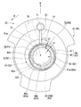
図2は、図1中に示された圧縮機構部33のF2−F2線に沿う断面図である。
図2に示すように、第1シリンダ41の内周面には、径方向Rの外側に向けて延びたベーン溝71が設けられている。このベーン溝71は、軸方向Zにおいて第1シリンダ41の全体に亘って形成されている。ベーン溝71には、径方向Rに沿ってスライド移動可能なベーン72が挿入されている。ベーン72は、図示しない付勢手段によって径方向Rの内側に向けて付勢され、その先端部が第1シリンダ室51内で第1ローラ46の外周面46aに当接している。これにより、ベーン72は、第1シリンダ室51の内部を、吸込室74と圧縮室75とに仕切っている。ベーン72は、第1ローラ46の偏心回転に伴って第1シリンダ室51内に進退する。このため、第1シリンダ室51内で第1ローラ46が偏心回転すると、第1ローラ46の偏心回転およびそれに伴うベーン72の進退動作によって、第1シリンダ室51内で気体冷媒を圧縮する圧縮動作が行われる。
FIG. 2 is a cross-sectional view taken along line F2-F2 of the
As shown in FIG. 2, a
また、第1シリンダ41には、吸込孔76と、吐出溝77とが設けられている。
吸込孔76は、第1シリンダ室51から径方向Rの外側に向けて第1シリンダ41を貫通している。吸込孔76の径方向Rの外側の端部には、上述した吸い込みパイプ21が接続されている。一方で、吸込孔76の径方向Rの内側の端部は、第1シリンダ室51の吸込室74に連通している。吸込孔76は、吸い込みパイプ21から送られた気体冷媒を第1シリンダ室51の吸込室74に流入させる。
The
The
一方で、吐出溝77は、圧縮室75に設けられている。吐出溝77は、第1シリンダ41の内周面に軸方向Zに沿って設けられ、主軸受44の吐出孔78(図1参照)に連通している。吐出溝77は、圧縮室75で圧縮された気体冷媒を主軸受44の吐出孔78に吐出する。主軸受44の吐出孔78に吐出された気体冷媒は、主軸受44の弁機構などを通じて密閉容器34内に排出される。一方で、第2シリンダ42に設けられた吐出溝77は、副軸受45の吐出孔79(図1参照)に連通している。第2シリンダ42の吐出溝77は、圧縮室75で圧縮された気体冷媒を副軸受45の吐出孔79に吐出する。副軸受45の吐出孔79に吐出された気体冷媒は、副軸受45の弁機構などを通じて密閉容器34内に排出される。
On the other hand, the
次に、圧縮機構部33に設けられた給油通路80について説明する。
図3は、圧縮機構部33の給油通路80を示す断面図である。
図3に示すように、給油通路80は、回転軸31に設けられた主通路81と、偏心部61,62に設けられた副通路82,83および連通路84,85とを有する。
Next, the
FIG. 3 is a cross-sectional view showing the
As shown in FIG. 3, the
主通路81は、軸線Oと同軸状に設けられ、回転軸31の内部に形成されている。主通路81は、軸方向Zに沿って回転軸31の内部を延びている。主通路81は、副軸受45に支持される回転軸31の端部において回転軸31の外部に開口している。ここで、密閉容器34内には、潤滑油Jが収容されており、圧縮機構部33の一部が潤滑油J内に浸かっている。主通路81には、密閉容器34に収容された潤滑油Jが流入する。また、主通路81の内部には、回転軸31の回転に伴って、潤滑油Jを主通路81内に汲み上げる螺旋構造が設けられている。
The
副通路82,83は、例えば偏心部61,62の外周面61a,62aに設けられた溝である。言い換えると、副通路82,83は、偏心部61,62の外周面61a,62aとローラ46,47の内周面46b,47bとの間に形成されている。副通路82,83は、軸方向Zに沿って延びており、軸方向Zにおいて偏心部61,62の全体に亘って形成されている。副通路82,83の端部は、ローラ46,47の内側の空間を通じて、仕切板43の開口部55に連通している。
The
連通路84,85は、径方向Rに沿って偏心部61,62の内部に設けられている。連通路84,85は、主通路81と副通路82,83との間に設けられ、主通路81と副通路82,83とを接続している。これにより、主通路81内の潤滑油Jは、回転軸31の回転に伴う遠心力によって、連通路84,85を通じて副通路82,83に供給される。副通路82,83に供給された潤滑油Jは、副通路82,83から圧縮機構部33の摺動部分に供給される。
The
次に、本実施形態の仕切板43について詳しく説明する。
上述したように、仕切板43は、回転軸31が通される開口部55を有する。図2に示すように、開口部55は、軸方向Zから見た平面視で円状に形成されている。開口部55の中心は、軸線Oと略一致する。すなわち、開口部55は、回転軸31と同軸状に設けられている。そして、本実施形態では、開口部55の内周面55bの少なくとも一部は、ローラ46,47の内周面46b,47bよりも回転軸31の径方向Rの外側に位置する。
Next, the
As described above, the
さらに言うと、本実施形態では、開口部55の内周面55bの内径は、偏心部61,62の外周面61a,62aの外径よりも大きい。すなわち、本実施形態の開口部55は、該開口部55の内側を偏心部61,62が軸方向Zに通されることができる大きさを有する。本実施形態の仕切板43は、1つの部材(例えば1枚の板材)で形成されている。すなわち、本実施形態の仕切板43は、分割された複数のピースが連結されることで複数の偏心部61,62の間に配置される仕切板ではない。本実施形態の仕切板43は、回転式圧縮機2の組立時に、複数の偏心部61,62のうち一方の偏心部61(または偏心部62)が開口部55に通されることで、複数の偏心部61,62の間に配置される仕切板である。このような仕切板43によれば、分割された複数のピースから成る仕切板に比べて、製造コストや組立工数の面で有利である。
Furthermore, in this embodiment, the inner diameter of the inner
次に、本実施形態のローラの構成について詳しく説明する。
ここで、第1ローラ46の構成と第2ローラ47の構成は、互いに略同じである。このため、ここでは第1ローラ46の構成を代表して説明する。そして、第2ローラ47において第1ローラ46と同一の機能を有する構成には、同一の符号を付してその説明を省略する。
Next, the configuration of the roller of this embodiment will be described in detail.
Here, the configuration of the
図2に示すように、第1ローラ46は、同心円状に配置された複数のサブローラ91,92から構成されている。本願で言う「サブローラ」とは、直径が異なる1つ以上の他のサブローラと組み合わされることで、1つのローラを構成する筒状の部材を意味する。本実施形態では、第1ローラ46は、複数のサブローラとして、内側ローラ91(第1サブローラ)と、外側ローラ92(第2サブローラ)とを有する。すなわち、第1ローラ46は、内側ローラ91と外側ローラ92とによって二重構造に形成されている。
As shown in FIG. 2, the
内側ローラ91は、外周面91aと、内周面91bとを有する。内側ローラ91の内周面91bは、第1ローラ46の内周面46bを形成している。すなわち、内側ローラ91の内周面91bは、偏心部61の外周面61aに嵌められている。これにより、内側ローラ91は、偏心部61の偏心回転に伴って第1シリンダ室51内で偏心回転する。ただし、内側ローラ91の内周面91bと偏心部61の外周面61aとの間には、偏心部61に対する内側ローラ91の相対回転を許容する隙間が設けられている。このため、内側ローラ91の自転速度は、回転軸31の回転速度よりも遅くなる。
The
一方で、外側ローラ92は、内側ローラ91の外周側に配置されている。外側ローラ92は、外周面92aと、内周面92bとを有する。外側ローラ92の外周面92aは、第1ローラ46の外周面46aを形成している。すなわち、外側ローラ92の外周面92aは、シリンダ室51の内周面に沿って摺動するともに、ベーン72の先端部が当接している。外側ローラ92の内周面92bは、内側ローラ91の外周面91aに嵌められている。これにより、外側ローラ92は、内側ローラ91の偏心回転に伴って第1シリンダ室51内で偏心回転する。ただし、外側ローラ92の内周面92bと内側ローラ91の外周面91aとの間には、内側ローラ91に対する外側ローラ92の相対回転を許容する隙間が設けられている。このため、外側ローラ92の自転速度は、内側ローラ91の自転速度よりも遅くなる。これにより、第1ローラ46が1つの筒部材で形成された場合に比べて、ベーン72の先端部に対する第1ローラ46の外周面46aの摺動速度が小さくなり、ベーン72の先端部の摩耗および第1ローラ46の外周面46aの摩耗が低減する。
On the other hand, the
ここで本実施形態では、図2に示すように、内側ローラ91の外周面91aは、第1ローラ46の全周に亘って、仕切板43の開口部55の内周面55bよりも径方向Rの外側に位置する。言い換えると、内側ローラ91と外側ローラ92との境界部Bは、第1ローラ46の全周に亘って、仕切板43の開口部55の内周面55bよりも径方向Rの外側に位置する。すなわち、内側ローラ91と外側ローラ92との間の境界部Bは、軸方向Zにおいて、仕切板43の開口部55に対して面していない。
Here, in this embodiment, as shown in FIG. 2, the outer
本実施形態では、内側ローラ91の径方向Rの肉厚t1は、外側ローラ92の径方向Rの肉厚t2よりも厚い。例えば、内側ローラ91の径方向Rの肉厚t1は、外側ローラ92の径方向Rの肉厚t2の2倍以上の厚さである。また、内側ローラ91の重量は、外側ローラ92の重量よりも重い。例えば、内側ローラ91を形成している材料の比重は、外側ローラ92を形成している材料の比重よりも大きい。内側ローラ91は、例えば金属製である。具体的な一例では、内側ローラ91の素材は、モニクロ鋳鉄(モリブデン、クロム、ニッケルを含有する鋳鉄)である。一方で、外側ローラ92は、例えばカーボン製である。
In the present embodiment, the thickness t1 of the
このように構成された回転式圧縮機2では、電動機部32の固定子36のコイルに電流が供給されることで、回転子37とともに回転軸31が軸線O周りに回転する。そして、回転軸31の回転に伴い、偏心部61,62およびローラ46,47がシリンダ室51,52内で偏心回転する。このとき、ローラ46,47がシリンダ41,42の内周面にそれぞれ摺接することで、吸込孔76を通じてシリンダ室51,52内に気体冷媒が取り込まれるとともに、シリンダ室51,52内に取り込まれた気体冷媒が圧縮される。圧縮された気体冷媒は、吐出溝77から主軸受44および副軸受45の吐出孔78,79を通って密閉容器34内に吐出される。密閉容器34内に吐出された気体冷媒は、上述したように放熱器3に送り込まれる。
In the rotary compressor 2 configured as described above, the rotating
上記のような回転式圧縮機2の運転中では、仕切板43の開口部55の内部の圧力は、密閉容器34内の圧力である吐出圧力Pd(以下、単に「圧力Pd」と称する。)と略同じになる。これは、仕切板43の開口部55の内部は、圧縮機構部33に設けられた給油通路80などを通じて密閉容器34の内部空間と連通しているためである。例えば、仕切板43の開口部55の内部は、密閉容器34内に貯留された潤滑油Jが給油通路80を通じて流入することで圧力Pdとなる。一方で、シリンダ室51,52の吸込室74の圧力は、ローラ46,47が偏心回転することで、圧力Pdよりも低い吸込圧力Ps(以下、単に「圧力Ps」と称する。)となる。
During the operation of the rotary compressor 2 as described above, the pressure inside the
ここで、本実施形態では、内側ローラ91の外周面91aは、ローラ46,47の全周に亘って、仕切板43の開口部55の内周面55bよりも径方向Rの外側に位置する。すなわち、内側ローラ91と外側ローラ92との境界部Bは、ローラ46,47の全周に亘って、仕切板43の開口部55の内周面55bよりも径方向Rの外側に位置し、開口部55には直接に臨まない。このため、内側ローラ91と外側ローラ92との境界部Bには、開口部55の内部の圧力Pdが直接には加わらない。そのため、内側ローラ91と外側ローラ92との境界部Bの圧力は、ローラ46,47の全周に亘って、圧力Pdよりも低い圧力Pd´となる。圧力Pd´は、圧力Pdよりも低く、圧力Psよりも高い圧力である。
Here, in the present embodiment, the outer
このような構成の回転式圧縮機2によれば、回転式圧縮機2の性能(例えば圧縮性能)を高めることができる。例えば、回転式圧縮機のローラとして、内側ローラと外側ローラとを含む二重構造が採用される場合がある。このような二重構造のローラによれば、高差圧、高回転域で回転式圧縮機2が運転される際でも、ローラが1つの筒部材で形成される場合に比べて、ベーンに対するローラの摺動速度を低下させることができる。これにより、ベーンとローラとの間の摺動部で生じる摩耗や摺動損失の改善、また摺動部の温度上昇を抑えることできる。 According to the rotary compressor 2 having such a configuration, the performance (for example, compression performance) of the rotary compressor 2 can be improved. For example, a double structure including an inner roller and an outer roller may be employed as a roller of the rotary compressor. According to such a double-structured roller, even when the rotary compressor 2 is operated in a high differential pressure and high rotation range, the roller with respect to the vane is compared with the case where the roller is formed of one cylindrical member. The sliding speed can be reduced. As a result, it is possible to improve the wear and sliding loss that occur at the sliding portion between the vane and the roller, and to suppress the temperature rise of the sliding portion.
ところで、上述したように、回転式圧縮機2の運転中では、仕切板43の開口部55の内部の圧力は、密閉容器34内の圧力である吐出圧力Pdと略同じになる。一方で、シリンダ室51,52の吸込室74の圧力は、圧力Pdよりも低い吸込圧力Psとなる。このため、仕切板43の開口部55に達した潤滑油Jに含まれる高圧の気体冷媒(以下、高圧冷媒と称する。)が、圧力Pdと圧力Psとの圧力差によって、仕切板43の開口部55からシリンダ室51,52の吸込室74にリークしようとする。
Incidentally, as described above, during the operation of the rotary compressor 2, the pressure inside the
ここで、内側ローラと外側ローラとの境界部の一部が仕切板の開口部の内周面よりも回転軸の径方向の内側に位置する場合、内側ローラと外側ローラとの境界部の一部が開口部55に直接に臨むことになる。この場合、内側ローラと外側ローラとの境界部には、開口部の内部の圧力Pdが直接に加わる。その結果、内側ローラと外側ローラとの境界部の圧力は、ローラの全周に亘って、密閉容器の吐出圧力Pdと略同じ圧力になる。このため上記構造では、圧力Pdと圧力Psとの圧力差に基づく高圧冷媒のリークを、外側ローラのみでシールすることになる。ただし、圧力Pdと圧力Psとの圧力差は比較的大きいため、シール幅(外周面92aと内周面92b間の距離)の小さい外側ローラだけでは十分にシールすることが難しい。このため、仕切板43の開口部55からシリンダ室51,52の吸込室74に高圧冷媒がリークする。その結果、吸込室74が外部から吸い込む気体冷媒の量が減少し、圧縮効率が低下する。そのため、回転式圧縮機の性能が低下する場合がある。
Here, when a part of the boundary portion between the inner roller and the outer roller is located on the inner side in the radial direction of the rotation shaft with respect to the inner peripheral surface of the opening of the partition plate, one of the boundary portions between the inner roller and the outer roller is disposed. The part faces the
一方で、本実施形態では、内側ローラ91の外周面91aは、ローラ46,47の全周に亘って、仕切板43の開口部55の内周面55bよりも径方向Rの外側に位置する。すなわち、内側ローラ91と外側ローラ92との境界部Bは、開口部55には直接には臨まない。このため、内側ローラ91と外側ローラ92との境界部Bには、開口部55の内部の圧力Pdが直接には加わらない。このため、内側ローラ91と外側ローラ92との境界部Bの圧力は、ローラ46,47の全周に亘って、密閉容器34の吐出圧力Pdよりも低い圧力Pd´となる。すなわち本実施形態の構造では、外側ローラ92によってシールする必要がある圧力差を、圧力Pd´と圧力Psとによる圧力差まで小さくすることができる。このため、仕切板43の開口部55からシリンダ室51,52の吸込室74にリークする高圧冷媒のリーク量を減少させることができる。その結果、吸込室74が外部から吸い込む気体冷媒の量が減少することを抑制し、圧縮効率が低下することを抑制することができる。これにより、回転式圧縮機2の性能向上を図ることができる。すなわち、二重構造のローラ46,47を有して摩耗や摺動損失の面で有利であるとともに、圧縮効率を高めることができる回転式圧縮機2を提供することができる。
On the other hand, in the present embodiment, the outer
本実施形態では、内側ローラ91の径方向Rの肉厚t1は、外側ローラ92の径方向Rの肉厚t2よりも厚い。このような構成によれば、内側ローラ91の外周面91aを、ローラ46,47の全周に亘って、仕切板43の開口部55の内周面55bよりも径方向Rの外側に位置させやすくなる。言い換えると、上記構成によれば、偏心部61,62の直径や、ローラ46,47の直径、または軸線Oに対する偏心部61,62の偏心量などの設計自由度が大きくなる。このため、さらなる性能向上を図ることができる回転式圧縮機2を提供することができる。
In the present embodiment, the thickness t1 of the
本実施形態では、内側ローラ91の重量は、外側ローラ92の重量よりも重い。このような構成によれば、外側ローラ92と内側ローラ91とが同じ重量である場合に比べて、外側ローラ92の自転速度を小さくすることができる。これにより、ベーン72と外側ローラ92との間の摺動部の摩擦や摺動抵抗などをさらに低減することができる。
In the present embodiment, the
そして、本実施形態の冷凍サイクル装置1によれば、上述した回転式圧縮機2を備えているため、性能向上を図ることができる冷凍サイクル装置1を提供できる。 And according to the refrigerating cycle apparatus 1 of this embodiment, since the rotary compressor 2 mentioned above is provided, the refrigerating cycle apparatus 1 which can aim at performance improvement can be provided.
以上、実施形態に係る回転式圧縮機2および冷凍サイクル装置1について説明したが、実施形態の構成は上記例に限定されない。
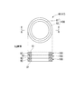
例えば、図4は、実施形態のローラ46,47の変形例を示す図である。
図4に示すように、ローラ46,47は、同心円状に配置された複数のサブローラ(例えば内側ローラ91と外側ローラ92)を含むサブローラセット100が、軸方向Zに複数段(例えば2段または3段)積層されることで形成されてもよい。このような構成によれば、複数段のサブローラセット100の間に形成される油膜によって、複数段のサブローラセット100のなかで軸方向Zの端部に位置するサブローラセット100を、仕切板43、主軸受44、または副軸受45に押し当てる力が生じる。このため、吸込室74および圧縮室75の密閉性が高まり、圧縮効率をさらに高めることができる。
Although the rotary compressor 2 and the refrigeration cycle apparatus 1 according to the embodiment have been described above, the configuration of the embodiment is not limited to the above example.
For example, FIG. 4 is a diagram illustrating a modified example of the
As shown in FIG. 4, each of the
また、上記実施形態では、内側ローラ91と外側ローラ92とを含む二重構造を有したローラ46,47について説明した。ただし、ローラ46,47は、同心円状に配置された3つ以上のサブローラを有してもよい。また、上記実施形態では、第1シリンダ室51の容積と第2シリンダ室52の容積とが互いに同じである場合について説明した。ただし、回転式圧縮機2は、第1シリンダ室51の容積と第2シリンダ室52の容積とが異なる異容積タイプの回転式圧縮機でもよい。また、回転式圧縮機2は、3つ以上のシリンダを備えるものでもよい。
In the above embodiment, the
また、上記実施形態では、内側ローラ91の径方向Rの肉厚t1が外側ローラ92の径方向Rの肉厚t2よりも大きい場合について説明した。ただし、内側ローラ91の径方向Rの肉厚t1は、外側ローラ92の径方向Rの肉厚t2と同じでもよく、それよりも小さくてもよい。また、内側ローラ91の重量は、外側ローラ92の重量と同じでもよく、それよりも軽くてもよい。また、内側ローラ91と外側ローラ92の素材は同じでもよい。また、仕切板43は、1つの部材で形成されたものに限らず、分割された複数のピースが連結されることで複数の偏心部61,62の間に配置される仕切板でもよい。
In the above embodiment, the case where the thickness t1 of the
本発明のいくつかの実施形態を説明したが、これらの実施形態は、例として提示したものであり、発明の範囲を限定することは意図していない。これら実施形態は、その他の様々な形態で実施されることが可能であり、発明の要旨を逸脱しない範囲で、種々の省略、置き換え、変更を行うことができる。これら実施形態やその変形は、発明の範囲や要旨に含まれると同様に、特許請求の範囲に記載された発明とその均等の範囲に含まれるものである。 Although several embodiments of the present invention have been described, these embodiments are presented by way of example and are not intended to limit the scope of the invention. These embodiments can be implemented in various other forms, and various omissions, replacements, and changes can be made without departing from the spirit of the invention. These embodiments and their modifications are included in the scope and gist of the invention, and are also included in the invention described in the claims and the equivalents thereof.
1…冷凍サイクル装置、2…回転式圧縮機、3…放熱器、4…膨張装置、5…蒸発器、31…回転軸、41,42…シリンダ、43…仕切板、46,47…ローラ、51,52…シリンダ室、55…仕切板の開口部、55b…開口部の内周面、61,62…回転軸の偏心部、61b,62b…ローラの内周面、72…ベーン、74…吸込室、75…圧縮室、91…内側ローラ(第1サブローラ)、91a…内側ローラの外周面、92…外側ローラ(第2サブローラ)、Z…軸方向、R…径方向、θ…周方向。 DESCRIPTION OF SYMBOLS 1 ... Refrigeration cycle apparatus, 2 ... Rotary compressor, 3 ... Radiator, 4 ... Expansion device, 5 ... Evaporator, 31 ... Rotating shaft, 41, 42 ... Cylinder, 43 ... Partition plate, 46, 47 ... Roller, 51, 52 ... Cylinder chamber, 55 ... Opening of partition plate, 55b ... Inner peripheral surface of opening, 61, 62 ... Eccentric part of rotating shaft, 61b, 62b ... Inner peripheral surface of roller, 72 ... Vane, 74 ... Suction chamber, 75 ... compression chamber, 91 ... inner roller (first sub roller), 91a ... outer peripheral surface of inner roller, 92 ... outer roller (second sub roller), Z ... axial direction, R ... radial direction, θ ... circumferential direction .
Claims (4)
前記シリンダ室内に配置される偏心部が設けられた回転軸と、
前記偏心部に嵌められて前記シリンダ室内で偏心回転する筒状のローラと、
前記ローラの偏心回転に伴って前記シリンダ室内に進退され、前記シリンダ室を吸込室と圧縮室とに仕切るベーンと、
前記複数のシリンダの間に配置されて前記シリンダ室の一面を規定するとともに、前記回転軸が通される開口部が設けられた仕切板と、
を備え、
前記仕切板の前記開口部の内周面の少なくとも一部は、前記ローラの内周面よりも前記回転軸の径方向の外側に位置し、
前記ローラは、同心円状に配置された複数のサブローラにより構成され、
前記複数のサブローラのうち最も内側に配置された第1サブローラの外周面は、前記ローラの全周に亘って、前記仕切板の前記開口部の内周面よりも前記径方向の外側に位置する、
回転式圧縮機。 A plurality of cylinders each forming a cylinder chamber;
A rotating shaft provided with an eccentric portion disposed in the cylinder chamber;
A cylindrical roller that is fitted in the eccentric part and rotates eccentrically in the cylinder chamber;
A vane that is advanced and retracted into the cylinder chamber with the eccentric rotation of the roller, and partitions the cylinder chamber into a suction chamber and a compression chamber;
A partition plate disposed between the plurality of cylinders to define one surface of the cylinder chamber and provided with an opening through which the rotating shaft is passed;
With
At least a part of the inner peripheral surface of the opening of the partition plate is located on the outer side in the radial direction of the rotating shaft than the inner peripheral surface of the roller,
The roller is constituted by a plurality of sub-rollers arranged concentrically,
The outer peripheral surface of the first sub-roller arranged on the innermost side among the plurality of sub-rollers is positioned on the outer side in the radial direction over the entire periphery of the roller, with respect to the inner peripheral surface of the opening of the partition plate. ,
Rotary compressor.
請求項1に記載の回転式圧縮機。 The plurality of sub-rollers include a second sub-roller disposed on the outer peripheral side of the first sub-roller, and the radial thickness of the first sub-roller is thicker than the radial thickness of the second sub-roller. ,
The rotary compressor according to claim 1.
請求項1または請求項2に記載の回転式圧縮機。 The plurality of sub-rollers includes a second sub-roller disposed on the outer peripheral side of the first sub-roller, and the weight of the first sub-roller is heavier than the weight of the second sub-roller,
The rotary compressor according to claim 1 or 2.
前記回転式圧縮機に接続された放熱器と、
前記放熱器に接続された膨張装置と、
前記膨張装置と前記回転式圧縮機との間に接続された吸熱器と、
を備えた冷凍サイクル装置。 The rotary compressor according to any one of claims 1 to 3,
A radiator connected to the rotary compressor;
An expansion device connected to the radiator;
A heat absorber connected between the expansion device and the rotary compressor;
A refrigeration cycle apparatus comprising:
Priority Applications (1)
| Application Number | Priority Date | Filing Date | Title |
|---|---|---|---|
| JP2016025349A JP2017141802A (en) | 2016-02-12 | 2016-02-12 | Rotary compressor and refrigeration cycle equipment |
Applications Claiming Priority (1)
| Application Number | Priority Date | Filing Date | Title |
|---|---|---|---|
| JP2016025349A JP2017141802A (en) | 2016-02-12 | 2016-02-12 | Rotary compressor and refrigeration cycle equipment |
Publications (1)
| Publication Number | Publication Date |
|---|---|
| JP2017141802A true JP2017141802A (en) | 2017-08-17 |
Family
ID=59628934
Family Applications (1)
| Application Number | Title | Priority Date | Filing Date |
|---|---|---|---|
| JP2016025349A Pending JP2017141802A (en) | 2016-02-12 | 2016-02-12 | Rotary compressor and refrigeration cycle equipment |
Country Status (1)
| Country | Link |
|---|---|
| JP (1) | JP2017141802A (en) |
Cited By (3)
| Publication number | Priority date | Publication date | Assignee | Title |
|---|---|---|---|---|
| JP2019049247A (en) * | 2017-09-12 | 2019-03-28 | 株式会社東芝 | Roller unit and rotary compressor |
| JP2019183818A (en) * | 2018-04-17 | 2019-10-24 | 三菱重工サーマルシステムズ株式会社 | Piston rotor, crank shaft, rotary compressor, and method for assembling crank shaft |
| JP2021021359A (en) * | 2019-07-26 | 2021-02-18 | 東芝キヤリア株式会社 | Rotary compressor and refrigeration cycle device |
-
2016
- 2016-02-12 JP JP2016025349A patent/JP2017141802A/en active Pending
Cited By (5)
| Publication number | Priority date | Publication date | Assignee | Title |
|---|---|---|---|---|
| JP2019049247A (en) * | 2017-09-12 | 2019-03-28 | 株式会社東芝 | Roller unit and rotary compressor |
| JP2019183818A (en) * | 2018-04-17 | 2019-10-24 | 三菱重工サーマルシステムズ株式会社 | Piston rotor, crank shaft, rotary compressor, and method for assembling crank shaft |
| JP7063699B2 (en) | 2018-04-17 | 2022-05-09 | 三菱重工サーマルシステムズ株式会社 | How to assemble a crankshaft, rotary compressor, and crankshaft |
| JP2021021359A (en) * | 2019-07-26 | 2021-02-18 | 東芝キヤリア株式会社 | Rotary compressor and refrigeration cycle device |
| JP7293024B2 (en) | 2019-07-26 | 2023-06-19 | 東芝キヤリア株式会社 | Rotary compressor and refrigeration cycle equipment |
Similar Documents
| Publication | Publication Date | Title |
|---|---|---|
| JP6022247B2 (en) | Hermetic compressor and refrigeration cycle apparatus | |
| JP5366856B2 (en) | Vane rotary type fluid apparatus and compressor | |
| JP6762253B2 (en) | Revolver and refrigeration cycle equipment | |
| CN108457858B (en) | Rotary compressor and refrigeration cycle device | |
| JP2015113817A (en) | Scroll type compressor | |
| JP6083408B2 (en) | Vane type compressor | |
| JP2017141802A (en) | Rotary compressor and refrigeration cycle equipment | |
| JP7113091B2 (en) | Rotary compressor, method for manufacturing rotary compressor, and refrigeration cycle device | |
| JP6148993B2 (en) | Rotary compressor and refrigeration cycle apparatus | |
| JP6735662B2 (en) | Rotary compressor and refrigeration cycle device | |
| JP2016160793A (en) | Rotary compressor and refrigeration cycle apparatus | |
| JP6374732B2 (en) | Rotary compressor and refrigeration cycle apparatus | |
| JP6758412B2 (en) | Revolver and refrigeration cycle equipment | |
| JP6441119B2 (en) | Rotary compressor and refrigeration cycle apparatus | |
| JP7195446B2 (en) | Multi-stage rotary compressor and refrigeration cycle device | |
| JP2019060268A (en) | Rotary compressor and refrigeration cycle device | |
| JP7186242B2 (en) | Rotary compressor and refrigeration cycle equipment | |
| JP2017180347A (en) | Vane type compressor | |
| JP6454236B2 (en) | Rotary compressor and refrigeration cycle apparatus | |
| JP6405119B2 (en) | Rotary compressor and refrigeration cycle apparatus | |
| JP2015055237A (en) | Rotary compressor and refrigeration cycle equipment | |
| JP5045471B2 (en) | Expansion machine | |
| JP7400080B2 (en) | Rotary compressor and refrigeration cycle equipment | |
| JP6430904B2 (en) | Compressor and refrigeration cycle apparatus | |
| JP2015148230A (en) | Hermetic type compressor and refrigeration cycle device |