JP2017142010A - Ventilation system and ventilation method - Google Patents

Ventilation system and ventilation method Download PDF

Info

Publication number
JP2017142010A
JP2017142010A JP2016022866A JP2016022866A JP2017142010A JP 2017142010 A JP2017142010 A JP 2017142010A JP 2016022866 A JP2016022866 A JP 2016022866A JP 2016022866 A JP2016022866 A JP 2016022866A JP 2017142010 A JP2017142010 A JP 2017142010A
Authority
JP
Japan
Prior art keywords
air
living room
fan
passage
vent
Prior art date
Legal status (The legal status is an assumption and is not a legal conclusion. Google has not performed a legal analysis and makes no representation as to the accuracy of the status listed.)
Pending
Application number
JP2016022866A
Other languages
Japanese (ja)
Inventor
林 智彦
Tomohiko Hayashi
智彦 林
Current Assignee (The listed assignees may be inaccurate. Google has not performed a legal analysis and makes no representation or warranty as to the accuracy of the list.)
Azbil Corp
Original Assignee
Azbil Corp
Priority date (The priority date is an assumption and is not a legal conclusion. Google has not performed a legal analysis and makes no representation as to the accuracy of the date listed.)
Filing date
Publication date
Application filed by Azbil Corp filed Critical Azbil Corp
Priority to JP2016022866A priority Critical patent/JP2017142010A/en
Publication of JP2017142010A publication Critical patent/JP2017142010A/en
Pending legal-status Critical Current

Links

Images

Landscapes

  • Building Environments (AREA)

Abstract

【課題】隣の空間との間での空気の移動を制御することができる通気システムを得る。【解決手段】居室2aと通路2cとを仕切る内壁には、ファン12a,12bを備えた通気口10a,10bが設けられている。ファン12aは、居室2aから吸気して通路2cへ排気するように回転するファンであり、ファン12bは、通路2cから吸気して居室2aへ排気するように回転するファンである。ファン12a,12bが回転を始めると、矢印F1で示すような流れで、居室2aと通路2cとの間を空気が移動する。【選択図】図2A ventilation system capable of controlling the movement of air between adjacent spaces is provided. Vents 10a and 10b having fans 12a and 12b are provided on an inner wall that partitions a living room 2a and a passage 2c. The fan 12a is a fan that rotates so as to suck air from the living room 2a and exhaust it to the passage 2c, and the fan 12b is a fan that rotates so as to suck air from the passage 2c and exhaust it to the living room 2a. When the fans 12a and 12b start rotating, the air moves between the living room 2a and the passage 2c in the flow shown by the arrow F1. [Selection] Figure 2

Description

この発明は、居室と通路の間等、異なる空間の間を空気が移動できるように、建物に設けられる通気システムに関するものである。   The present invention relates to a ventilation system provided in a building so that air can move between different spaces such as between a living room and a passage.

建物に導入される空調システムとしては、様々なものが従来から知られており、空調システムごとに適した建物のタイプが存在する。例えば、空調したい居室ごとにエアコン等の空調機器を設置する個別空調の場合、通常、各居室は、他の居室及び通路に対して閉じた空間となるように設計される。また、特許文献1のような複数の居室を対象に空調を行う全館空調の場合、通常、各居室は、他の居室及び通路に対して開いた空間となるように設計される。具体的には、内壁に設けた開口であるリターンパスや、ドアのアンダーカット等を介して、他の居室及び通路との間での空気の移動が可能に設計されることが多い。   Various types of air conditioning systems to be introduced into buildings are conventionally known, and there are types of buildings suitable for each air conditioning system. For example, in the case of individual air conditioning in which an air conditioner such as an air conditioner is installed for each living room to be air-conditioned, each room is usually designed to be a space closed with respect to other living rooms and passages. Moreover, in the case of the whole building air conditioning which air-conditions several living rooms like patent document 1, each living room is normally designed so that it may become a space open with respect to another living room and a channel | path. Specifically, it is often designed to allow movement of air between other living rooms and passages through a return path that is an opening provided in the inner wall, an undercut of a door, or the like.

特開平5−172371号公報JP-A-5-172371

しかしながら、上記のように設計された従来の建物では、隣り合う空間の間での空気の移動を制御することはできなかった。例えば、各居室が他の居室及び通路に対して閉じた空間となっている場合、隣の空間へ空気を排出したり、隣の空間の空気を取り入れたりしようにも、そもそもそのための開口部等が設けられていないので、空気の移動を制御することができない。また例えば、リターンパス、アンダーカットを介して隣り合う空間の間での空気の移動が可能なように設計されていても、空気は成り行きで移動してしまい、居住者側で制御することができない。このため、例えば居室の暖気をその隣室に移動させるなど、隣の空間を活用して快適な室内環境を得ることができなかった。   However, the conventional building designed as described above cannot control the movement of air between adjacent spaces. For example, if each living room is a closed space with respect to other living rooms and passages, it may be necessary to exhaust air into the adjacent space or take in the air in the adjacent space. Is not provided, the movement of air cannot be controlled. For example, even if it is designed to allow air to move between adjacent spaces via return paths and undercuts, the air will move in a random manner and cannot be controlled by the resident side. . For this reason, for example, it was not possible to obtain a comfortable indoor environment by utilizing the adjacent space such as moving the warm air of the living room to the adjacent room.

この発明は、上記のような課題を解決するためになされたもので、隣の空間との間での空気の移動を制御することができる通気システムを得ることを目的とする。   The present invention has been made to solve the above-described problems, and an object thereof is to obtain a ventilation system capable of controlling the movement of air between adjacent spaces.

この発明に係る通気システムは、同じ空間に面する内壁に設けられた通気口を複数備え、複数の通気口は、内壁を貫通する開口部をそれぞれ有し、複数の通気口のうち少なくとも1つの通気口は、その開口部にファンが設けられていることを特徴とするものである。   The ventilation system according to the present invention includes a plurality of ventilation holes provided on an inner wall facing the same space, each of the plurality of ventilation holes having an opening penetrating the inner wall, and at least one of the plurality of ventilation holes. The vent is characterized in that a fan is provided in the opening.

この発明によれば、複数の通気口のうち少なくとも1つの通気口の開口部にファンを設けたので、隣の空間との間での空気の移動を制御することができる。   According to this invention, since the fan is provided at the opening of at least one of the plurality of vents, the movement of air between the adjacent spaces can be controlled.

この発明の実施の形態1に係る通気システムを設けた建物の概略図である。It is the schematic of the building which provided the ventilation system which concerns on Embodiment 1 of this invention. この発明の実施の形態1に係る通気システムの通気口を示す斜視図である。It is a perspective view which shows the vent hole of the ventilation system which concerns on Embodiment 1 of this invention. この発明の実施の形態1に係る通気システムの通気口を示す斜視図であり、図2とは異なる方向に空気が移動する場合を示す。It is a perspective view which shows the vent of the ventilation system which concerns on Embodiment 1 of this invention, and shows the case where air moves to the direction different from FIG. この発明の実施の形態1に係る通気システムの通気口の配置の第1変形例を示す斜視図である。It is a perspective view which shows the 1st modification of arrangement | positioning of the vent of the ventilation system which concerns on Embodiment 1 of this invention. この発明の実施の形態1に係る通気システムの通気口の配置の第2変形例を示す斜視図である。It is a perspective view which shows the 2nd modification of arrangement | positioning of the vent of the ventilation system which concerns on Embodiment 1 of this invention.

実施の形態1.
図1は、この発明の実施の形態1に係る通気システムを設けた建物の概略図である。居室1a,1bが1階、居室2a,2bが2階にあり、居室1a,1bは通路1c、居室2a,2bは通路2cに面している。1階の通路1cと2階の通路2cとは、階段3で吹き抜けのように繋がっている。そして、この建物では、屋内の暖冷房を行うために全館空調システムが導入されているとして以下説明する。
Embodiment 1 FIG.
1 is a schematic view of a building provided with a ventilation system according to Embodiment 1 of the present invention. The living rooms 1a and 1b are on the first floor, the living rooms 2a and 2b are on the second floor, the living rooms 1a and 1b face the passage 1c, and the living rooms 2a and 2b face the passage 2c. The passage 1c on the first floor and the passage 2c on the second floor are connected in a staircase 3 like an atrium. In this building, the whole building air conditioning system is introduced to perform indoor heating and cooling.

全館空調システムでは、室外機4と、室外機4に不図示の冷媒の循環ラインを介して接続する室内機5との協働により、冷風又は温風の調和空気が生成される。
室外機4は、外気と冷媒を熱交換させるものであり、圧縮機、水冷式の熱交換器(又は空冷式の熱交換器とファン)等を有する。
室内機5は、例えば天井裏に設置され、熱交換器、ファン等を有する。室内機5は、室外機4から冷媒の循環ラインを介して送られた冷媒と、後述の換気装置8から送られる空気とを熱交換器で熱交換させる。そして、熱交換後の調和空気をファンにより送り出す。室内機5が送り出した調和空気は、不図示のサプライダクトを介して、吹出し口6から各居室へ吹き出される。
In the entire building air conditioning system, cold air or warm air conditioned air is generated by the cooperation of the outdoor unit 4 and the indoor unit 5 connected to the outdoor unit 4 via a refrigerant circulation line (not shown).
The outdoor unit 4 exchanges heat between the outside air and the refrigerant, and includes a compressor, a water-cooled heat exchanger (or an air-cooled heat exchanger and a fan), and the like.
The indoor unit 5 is installed behind the ceiling, for example, and includes a heat exchanger, a fan, and the like. The indoor unit 5 exchanges heat between the refrigerant sent from the outdoor unit 4 via the refrigerant circulation line and the air sent from the ventilator 8 described later using a heat exchanger. And the conditioned air after heat exchange is sent out by a fan. The conditioned air sent out by the indoor unit 5 is blown out from the outlet 6 to each room through a supply duct (not shown).

吹出し口6から吹き出された調和空気は、内壁に設けられリターンパスとしても機能する通気口10、ドアのアンダーカット等、居室内外での空気の移動が可能な開口を介して通路1c,2c及び階段3等へも行き渡り、全館が空調される。
全館空調システムでは、通路2cの天井側に設けられた吸込み口7を介して、屋内の戻り空気を取り入れる。吸込み口7から取り入れた戻り空気は、換気装置8により建物外へ排気される。換気装置8は、外気の取入れも担っており、取り入れた外気は、室内機5へと送られる。
The conditioned air blown out from the blow-out opening 6 is provided on the inner wall and functions as a return path. The passage 10c, 2c, The entire building is air-conditioned by going to the stairs 3 etc.
In the entire building air conditioning system, indoor return air is taken in through a suction port 7 provided on the ceiling side of the passage 2c. The return air taken in from the suction port 7 is exhausted outside the building by the ventilation device 8. The ventilator 8 also takes in outside air, and the taken-in outside air is sent to the indoor unit 5.

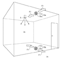
ここで、図2に、屋内の空間である居室2aと通路2cとを仕切る内壁に設けた通気口10を、通路2cから居室2aを見た際の斜視図で示す。
居室2aと通路2cとを仕切る内壁には、通気口10a,10bという2つの通気口10が設けられている。通気口10aは、通気口10bよりも鉛直方向で上側、つまり天井側に設けられ、通気口10bは、通気口10aよりも鉛直方向で下側、つまり床側に設けられている。
Here, FIG. 2 is a perspective view of the vent 10 provided on the inner wall that partitions the living room 2a and the passage 2c, which are indoor spaces, when the living room 2a is viewed from the passage 2c.
On the inner wall that partitions the living room 2a and the passage 2c, two vent holes 10a and 10b are provided. The vent hole 10a is provided above the vent hole 10b in the vertical direction, that is, on the ceiling side, and the vent hole 10b is provided vertically below the vent hole 10a, that is, on the floor side.

通気口10aは、居室2aと通路2cとを仕切る内壁を貫通する開口部11aと、開口部11aに嵌め込むようにして設けられたファン12a等で構成されている。同様に、通気口10bは、居室2aと通路2cとを仕切る内壁を貫通する開口部11bと、開口部11bに嵌め込むようにして設けられたファン12b等で構成されている。
ファン12a,12bの回転は、通気システムの不図示の制御部により制御される。そして、この制御部には、不図示のリモコン等を介して居住者が、ファン12a,12bの回転、停止、回転量等の希望する回転状態を指示できるよう構成されている。
The vent 10a includes an opening 11a penetrating an inner wall that partitions the living room 2a and the passage 2c, a fan 12a provided so as to be fitted into the opening 11a, and the like. Similarly, the vent 10b includes an opening 11b penetrating an inner wall that partitions the living room 2a and the passage 2c, and a fan 12b provided so as to be fitted into the opening 11b.
The rotation of the fans 12a and 12b is controlled by a control unit (not shown) of the ventilation system. The control unit is configured such that a resident can instruct a desired rotation state such as rotation, stop, and rotation amount of the fans 12a and 12b via a remote controller (not shown).

次に、通気口10a,10bのファン12a,12bの運転例について説明する。
ファン12aとしては、例えば居室2aから吸気して通路2cへ排気するように回転するファンが用いられる。そして、ファン12bとしては、例えば通路2cから吸気して居室2aへ排気するように回転するファンが用いられる。
Next, an operation example of the fans 12a and 12b of the vent holes 10a and 10b will be described.
As the fan 12a, for example, a fan that rotates so as to suck air from the living room 2a and exhaust it to the passage 2c is used. As the fan 12b, for example, a fan that rotates so as to suck air from the passage 2c and exhaust it to the living room 2a is used.

このようなファン12a,12bが、不図示の制御部に制御されて回転を始めると、図2に矢印F1で示すような流れで、居室2aと通路2cとの間を空気が移動する。すなわち、居室2aの床側の通気口10bから通路2cの空気が居室2aに入り、居室2aの天井側の通気口10aから居室2aの空気が通路2cへ抜けていく。   When such fans 12a and 12b start to rotate under the control of a control unit (not shown), the air moves between the room 2a and the passage 2c in the flow shown by the arrow F1 in FIG. In other words, the air in the passage 2c enters the living room 2a from the vent 10b on the floor side of the living room 2a, and the air in the living room 2a passes through the vent 10a on the ceiling side of the living room 2a to the passage 2c.

このようにして居室2aと通路2cとの間を空気が移動すると、居室2aが冷房されている場合に、床側に冷気が分布しやすいという居室2a内の鉛直方向の温度斑を低減するのに有効である。また、天井側に溜まった暖気が通路2cへ抜けていくので、居室2aが涼しくなり、居室2aの室内環境が快適になる。
また、暖房時であっても、居室2aが温まり過ぎた場合、天井側に溜まった暖気を通路2cへ逃がすことができ、居室2aの室内環境が快適になる。これは、全館空調システムでは、吹出し口6の無い通路1c,2cに対して、居室1a〜2bには多数の吹出し口6が設けられるために、居室1a〜2b内が空調過多となりやすいからである。
また、全館空調システムが、室内機5での熱交換を行わず、外気を吹出し口6から吹き出して換気のみを行っている時にも、矢印F1のように居室2aと通路2cとの間で空気を移動させることにより、通路2cを利用して居室2aの室内環境を調節することができる。例えば、通路2cが涼しく、その涼しい空気を居室2aに取り入れたい場合に、有用である。
When air moves between the living room 2a and the passage 2c in this way, when the living room 2a is cooled, the temperature spots in the vertical direction in the living room 2a such that cold air is likely to be distributed on the floor side are reduced. It is effective for. Moreover, since the warm air accumulated on the ceiling side passes through the passage 2c, the living room 2a becomes cool, and the indoor environment of the living room 2a becomes comfortable.
Further, even during heating, if the living room 2a is too warm, the warm air accumulated on the ceiling side can be released to the passage 2c, and the indoor environment of the living room 2a becomes comfortable. This is because, in the entire building air conditioning system, since the numerous air outlets 6 are provided in the living rooms 1a to 2b with respect to the passages 1c and 2c having no air outlet 6, the air conditioners 1a to 2b are likely to be excessively air-conditioned. is there.
Also, when the entire building air conditioning system does not perform heat exchange in the indoor unit 5 and only ventilates by blowing outside air from the outlet 6, the air between the room 2 a and the passage 2 c as indicated by the arrow F <b> 1. The indoor environment of the living room 2a can be adjusted using the passage 2c. For example, this is useful when the passage 2c is cool and the cool air is to be taken into the living room 2a.

図2に示すような、居室2aの床側の通気口10bから通路2cの空気が居室2aに入り、居室2aの天井側の通気口10aから居室2aの空気が通路2cへ抜けていく空気の移動は、回転すると居室2aから吸気して通路2cへ排気するファン12aのみを回転させることにより、生じさせてもよい。この場合、ファン12bは回転させないか、あるいは、通気口10bにファン12bを備えて無くともよい。同様に、回転すると通路2cから吸気して居室2aへ排気するファン12bのみを回転させてもよく、この場合ファン12aは回転させないか、あるいは、通気口10aにファン12aを備えて無くともよい。   As shown in FIG. 2, the air in the passage 2c enters the room 2a from the floor side vent 10b of the living room 2a, and the air in the room 2a passes from the ceiling side vent 10a to the passage 2c. The movement may be caused by rotating only the fan 12a that draws air from the living room 2a and exhausts it into the passage 2c when it rotates. In this case, the fan 12b may not be rotated, or the air vent 10b may not be provided with the fan 12b. Similarly, when rotating, only the fan 12b that sucks air from the passage 2c and exhausts it to the living room 2a may be rotated. In this case, the fan 12a may not be rotated, or the air vent 10a may not include the fan 12a.

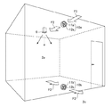
ファン12aとしては、他にも例えば通路2cから吸気して居室2aへ排気するように回転するファンが用いられる。そして、ファン12bとしては、他にも例えば居室2aから吸気して通路2cへ排気するように回転するファンが用いられる。
このようなファン12a,12bが、不図示の制御部に制御されて回転を始めると、図3に矢印F2で示すような流れで、居室2aと通路2cとの間を空気が移動する。すなわち、居室2aの天井側の通気口10aから通路2cの空気が居室2aに入り、居室2aの床側の通気口10bから居室2aの空気が通路2cへ抜けていく。
As the fan 12a, for example, a fan that rotates so as to suck air from the passage 2c and exhaust it to the living room 2a is used. Further, as the fan 12b, for example, a fan that rotates so as to suck air from the living room 2a and exhaust it to the passage 2c is used.
When such fans 12a and 12b start to rotate under the control of a control unit (not shown), the air moves between the room 2a and the passage 2c in the flow shown by the arrow F2 in FIG. That is, the air in the passage 2c enters the living room 2a from the vent 10a on the ceiling side of the living room 2a, and the air in the living room 2a passes through the vent 10b on the floor side of the living room 2a to the passage 2c.

このようにして居室2aと通路2cとの間を空気が移動すると、居室2aが暖房されている場合に、天井側に暖気が分布しやすいという居室2a内の鉛直方向の温度斑を低減するのに有効である。また、床側に溜まった冷気が通路2cへ抜けていくので、居室2aが暖かくなり、居室2aの室内環境が快適になる。
また、冷房時であっても、居室2aが冷え過ぎた場合、床側に溜まった冷気を通路2cへ逃がすことができ、居室2aの室内環境が快適になる。
また、全館空調システムが、室内機5での熱交換を行わず、外気を吹出し口6から吹き出して換気のみを行っている時にも、矢印F2のように居室2aと通路2cとの間で空気を移動させることにより、通路2cを利用して居室2aの室内環境を調節することができる。例えば、通路2cが暖かく、その暖かい空気を居室2aに取り入れたい場合に、有用である。
When air moves between the living room 2a and the passage 2c in this way, when the living room 2a is heated, the temperature spots in the vertical direction in the living room 2a that warm air tends to be distributed on the ceiling side are reduced. It is effective for. Moreover, since the cold air accumulated on the floor side passes through the passage 2c, the living room 2a becomes warm, and the indoor environment of the living room 2a becomes comfortable.
Even when the room 2a is cooling, if the room 2a is too cold, the cold air accumulated on the floor side can be released to the passage 2c, and the room environment of the room 2a becomes comfortable.
Also, when the entire building air conditioning system does not perform heat exchange in the indoor unit 5 and only ventilates by blowing outside air from the outlet 6, the air between the living room 2 a and the passage 2 c as indicated by the arrow F <b> 2. The indoor environment of the living room 2a can be adjusted using the passage 2c. For example, this is useful when the passage 2c is warm and the warm air is to be taken into the living room 2a.

図3に示すような、居室2aの天井側の通気口10aから通路2cの空気が居室2aに入り、居室2aの床側の通気口10bから居室2aの空気が通路2cへ抜けていく空気の移動は、回転すると通路2cから吸気して居室2aへ排気するファン12aのみを回転させることにより、生じさせてもよい。この場合、ファン12bは回転させないか、あるいは、通気口10bにファン12bを備えて無くともよい。同様に、回転すると居室2aから吸気して通路2cへ排気するファン12bのみを回転させてもよく、この場合ファン12aは回転させないか、あるいは、通気口10aにファン12aを備えて無くともよい。   As shown in FIG. 3, the air in the passage 2c enters the living room 2a from the vent 10a on the ceiling side of the living room 2a, and the air in the living room 2a passes from the vent 10b on the floor side of the living room 2a to the passage 2c. The movement may be caused by rotating only the fan 12a that draws air from the passage 2c and exhausts it to the living room 2a when it rotates. In this case, the fan 12b may not be rotated, or the air vent 10b may not be provided with the fan 12b. Similarly, when rotating, only the fan 12b that sucks air from the living room 2a and exhausts it to the passage 2c may be rotated. In this case, the fan 12a may not be rotated, or the air vent 10a may not include the fan 12a.

図2に矢印F1で示す空気の移動と、図3に矢印F2で示す空気の移動の双方を、ファン12a,12bとして用いるファンを付け替えることなく、同じファンで作り出すことができれば、状況に応じて矢印F1の流れと矢印F2の流れとを切り換えることが容易となり、好ましい。そのためには、例えば、ファン12a,12bとして、通路2cから吸気して居室2aへ排気するファンを通気口10a,10bに設け、状況に応じてどちらか1つのファン12a,12bのみを回転させればよい。ファン12aのみを回転させれば図3の矢印F2の流れ、ファン12bのみを回転させれば図2の矢印F1の流れが生じる。または、同じように、ファン12a,12bとして、居室2aから吸気して通路2cへ排気するファンを通気口10a,10bに設け、状況に応じてどちらか1つのファン12a,12bのみを回転させればよい。
または、正逆回転可能なファンを、ファン12a,12bの少なくともどちらかとして設け、状況に応じて正回転と逆回転とを切り換えればよい。例えば、ファン12aとして正逆回転可能なファンを用いれば、通気口10bにはファンを備えなくともよい。
または、図2に示す矢印F1の流れを生じさせる通気口10a,10bのペアと、図3に示す矢印F2の流れを生じさせる通気口10a,10bのペアを、それぞれ内壁に設けることで対応してもよい。
If both the movement of the air shown by the arrow F1 in FIG. 2 and the movement of the air shown by the arrow F2 in FIG. 3 can be made with the same fan without changing the fans used as the fans 12a and 12b, depending on the situation It is easy and preferable to switch the flow of the arrow F1 and the flow of the arrow F2. For this purpose, for example, as the fans 12a and 12b, a fan that sucks air from the passage 2c and exhausts it to the living room 2a is provided in the vent holes 10a and 10b, and only one of the fans 12a and 12b can be rotated according to the situation. That's fine. If only the fan 12a is rotated, the flow of the arrow F2 in FIG. 3 is generated, and if only the fan 12b is rotated, the flow of the arrow F1 in FIG. 2 is generated. Similarly, fans 12a and 12b are provided in the vents 10a and 10b as fans 12a and 12b for sucking air from the living room 2a and exhausting them to the passage 2c, and only one of the fans 12a and 12b can be rotated depending on the situation. That's fine.
Alternatively, a fan capable of forward and reverse rotation may be provided as at least one of the fans 12a and 12b, and the forward rotation and the reverse rotation may be switched depending on the situation. For example, if a fan capable of rotating in the forward and reverse directions is used as the fan 12a, the vent 10b may not include a fan.
Alternatively, a pair of vents 10a and 10b for generating the flow of the arrow F1 shown in FIG. 2 and a pair of vents 10a and 10b for generating the flow of the arrow F2 shown in FIG. May be.

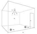
また、通気口10a,10bを、図4に示すように水平方向に並べて設けてもよい。居室2aへ通路2cの暖気又は冷気を取り入れたり、居室2aの暖気又は冷気を通路2cに逃がしたりして、通路2cを利用しながら居室2aの室内環境を調節したいときは、有用である。このとき、通気口10a,10bいずれか一方にファンが備わっていれば、他方にファンが備わっていなくとも構わない。
さらに、通気口10a,10bを、図5に示すように水平方向及び鉛直方向での位置が異なるように斜めに並べて設けてもよい。
Further, the vents 10a and 10b may be provided side by side in the horizontal direction as shown in FIG. This is useful when it is desired to adjust the indoor environment of the living room 2a while using the passage 2c by taking the warm air or cold air of the passage 2c into the living room 2a or letting the warm air or cold air of the living room 2a escape to the passage 2c. At this time, as long as one of the vents 10a and 10b has a fan, the other may not have a fan.
Further, the vent holes 10a and 10b may be provided obliquely so that the positions in the horizontal direction and the vertical direction are different as shown in FIG.

通気口10a,10bにより居室2aと通路2cとの間で空気を移動させることは、居室2aの換気にも有用である。居室2a内で通気口10aから通気口10bに向かう空気の流れ、または、居室2a内で通気口10bから通気口10aに向かう空気の流れが生じることで、居室2a内の空気は、発生した空気の流れに巻き込まれるようにして拡散して同じ場所に滞留しにくくなるので、室内が均一に換気されやすくなり、換気斑が低減される。   Moving air between the living room 2a and the passage 2c through the vents 10a and 10b is also useful for ventilation of the living room 2a. The flow of air from the vent 10a to the vent 10b in the living room 2a or the flow of air from the vent 10b to the vent 10a in the living room 2a occurs, so that the air in the living room 2a is generated air. Since it is difficult to stay in the same place by being diffused by being caught in the flow of the room, the room is easily ventilated uniformly, and ventilation spots are reduced.

このように、通気口10a,10bの少なくともいずれか一方にファンを備えることで、通気口10aと通気口10bとの間での空気の流れを制御する。これにより、居室2aと通路2cとの間での空気の移動を制御することが可能となり、居室2aの快適な室内環境を得ることができる。
また、ファン12a,12bにより通気口10aと通気口10bとの間を流れる空気は、吹出し口6から出るような吹き出し空気と異なり、気流が体に直接当たる不快感があまり無い。さらに、ファン12a,12bが通気口10a,10bの開口部11a,11bに納まっていることから、意匠性を損なうことも無い。
Thus, by providing a fan in at least one of the vents 10a and 10b, the flow of air between the vent 10a and the vent 10b is controlled. Thereby, it becomes possible to control the movement of air between the living room 2a and the passage 2c, and a comfortable indoor environment of the living room 2a can be obtained.
Further, the air flowing between the air vent 10a and the air vent 10b by the fans 12a and 12b is unlikely to be blown out from the air outlet 6, so that there is not much discomfort that the air current directly hits the body. Furthermore, since the fans 12a and 12b are accommodated in the openings 11a and 11b of the vents 10a and 10b, the design is not impaired.

ファン12a,12bの回転は、リモコン等を介した居住者による手動での制御の他に、通気システムの不図示の制御部が状況に応じて自動的に制御するように設計してもよい。制御部で自動的に制御する場合、温度センサを例えば居室2aと通路2c双方の床側と天井側に設け、検知した温度差に基づき、ファン12a,12bの回転を適宜の状態に制御するよう制御部をプログラムすればよい。また、全館空調システムにより暖房が行われているか、冷房が行われているか、外気の送風による換気のみが行われているかにより、居室2a内で通気口10aから通気口10bに向かう流れが生じるようにファン12a,12bの回転を制御するか、または、居室2a内で通気口10bから通気口10aに向かう流れが生じるようにファン12a,12bの回転を制御するかを一義的に判定するように制御部をプログラムしてもよい。暖房、冷房、換気のみ、のいずれが行われているかの判定は、全館空調システムから運転情報を得ること等により可能である。   The rotation of the fans 12a and 12b may be designed so that a control unit (not shown) of the ventilation system automatically controls according to the situation in addition to manual control by a resident through a remote controller or the like. In the case of automatic control by the control unit, for example, temperature sensors are provided on the floor side and the ceiling side of both the living room 2a and the passage 2c, and the rotation of the fans 12a and 12b is controlled to an appropriate state based on the detected temperature difference. What is necessary is just to program a control part. Further, depending on whether heating is performed by the entire building air conditioning system, cooling is performed, or only ventilation by blowing outside air is performed, a flow from the vent 10a toward the vent 10b is generated in the living room 2a. To determine whether to control the rotation of the fans 12a and 12b or to control the rotation of the fans 12a and 12b so that a flow from the vent 10b to the vent 10a occurs in the living room 2a. The control unit may be programmed. It is possible to determine whether heating, cooling, or ventilation only is performed by obtaining operation information from the entire building air conditioning system.

なお、上記では、全館空調システムにより空調が行われる建物に対して、実施の形態1の通気システムを適用した場合について説明した。しかしながら、全館空調ではなく、個別空調で空調されている建物に対して、実施の形態1の通気システムを適用してもよい。例えば、リビング等の大空間に個別の専用エアコンが設けられている場合を考える。この場合、その大空間と通路とを仕切る内壁に通気口10a,10bを設けるとともに、その通路と寝室等の他の居室とを仕切る内壁にも通気口10a,10bを設ける。そして、通路は大空間から調和空気を取り入れ、寝室等の居室は、通路を介して調和空気を利用する。具体的には、寝室等の居室では、冷房時であれば床側の通気口10bから通路の調和空気を取り入れ、暖房時であれば天井側の通気口10aから通路の調和空気を取り入れる。このようにすれば、寝室等の居室にエアコンが無かったり、容量不足のエアコンが設置されていたりする場合でも、他の空間を利用して暖冷房を行い、室内環境を快適にすることができる。また、全館空調システムと異なり、個別空調がされる建物には、換気のためのシステムが備わっていないことが多い。実施の形態1の通気システムを適用することで、人が居て空気が汚れやすい居室と、居室ほどは空気が汚れない通路等との間で空気を移動させることができるので、換気の面でも実施の形態1の通気システムを個別空調の建物に導入するメリットがある。   In the above description, the case where the ventilation system of the first embodiment is applied to a building that is air-conditioned by the entire building air conditioning system has been described. However, the ventilation system of the first embodiment may be applied to a building that is air-conditioned by individual air conditioning rather than whole-building air conditioning. For example, consider a case where a separate dedicated air conditioner is provided in a large space such as a living room. In this case, the vents 10a and 10b are provided on the inner wall that partitions the large space and the passage, and the vents 10a and 10b are also provided on the inner wall that partitions the passage and another living room such as a bedroom. And a passage takes in conditioned air from large space, and living rooms, such as a bedroom, use conditioned air through a passage. Specifically, in a living room such as a bedroom, the conditioned air in the passage is taken in from the floor-side vent 10b during cooling, and the conditioned air in the passage is taken in from the ceiling-side vent 10a during heating. In this way, even if there is no air conditioner in the living room such as a bedroom or an air conditioner with insufficient capacity is installed, the room environment can be made comfortable by heating and cooling using other spaces. . Also, unlike the entire building air conditioning system, buildings that are individually air-conditioned often do not have a ventilation system. By applying the ventilation system of the first embodiment, air can be moved between a room where people are present and the air is likely to get dirty, and a passage where air is not as dirty as the living room. There is a merit of introducing the ventilation system of Embodiment 1 into a building of individual air conditioning.

また、上記では、居室2aと通路2cとを仕切る内壁に2つの通気口10a,10bを設けた場合について説明した。しかしながら、居室2aと通路2cとを仕切る内壁に更に追加で通気口10を設けてもよい。そして、追加で設ける通気口10からは、適宜ファンを省略してもよい。
また、通気口10a,10bのうちの一方を、通路2c以外の空間と居室2aとを仕切る内壁に設けてもよい。要は、通気口10a,10bは、居室2aという屋内の同じ空間に面する内壁に設けられていればよい。
また、通気口10a,10bのうちの双方を、通路2c以外の空間と居室2aとを仕切る内壁に設けてもよい。当該内壁が居室2aとその隣の居室とを仕切る内壁であれば、居室間での空気の移動を制御することができる。
Moreover, the case where the two vent holes 10a and 10b were provided in the inner wall which partitions the living room 2a and the channel | path 2c was demonstrated above. However, the vent 10 may be additionally provided on the inner wall that partitions the living room 2a and the passage 2c. And you may abbreviate | omit a fan suitably from the vent hole 10 provided additionally.
Further, one of the vents 10a and 10b may be provided on the inner wall that partitions the space other than the passage 2c and the living room 2a. In short, the vents 10a and 10b may be provided on the inner wall facing the same indoor space 2a.
Moreover, you may provide both of vent hole 10a, 10b in the inner wall which partitions off the space other than the channel | path 2c, and the living room 2a. If the inner wall is an inner wall that separates the living room 2a from the adjacent living room, the movement of air between the living rooms can be controlled.

また、上記では、居室2aと通路2cとを仕切る内壁に設けた通気口10が、通気口10a,10bであるとして図2〜図5を用いて詳細に説明した。この説明との重複を避けるために説明は省略するが、図1に示すそれ以外の内壁に設けた通気口10も、同様の通気口10a,10bとなっている。   Moreover, in the above, it demonstrated in detail using FIGS. 2-5 that the vent hole 10 provided in the inner wall which partitions the living room 2a and the channel | path 2c was vent hole 10a, 10b. Although the description is omitted to avoid duplication with this description, the vent holes 10 provided on the other inner walls shown in FIG. 1 are also similar vent holes 10a and 10b.

また、上記では、居室2aに全館空調システムの吹出し口6を設けて、居室2aを空調した。つまり、空気温度を調節する温度調節部として、居室2aに吹出し口6を設けた。しかしながら、ファンヒータ等の種々の空調機器を居室2aに設け、温度調節部としてもよい。
また、居室2aに温度調節部が設けられていなくともよく、この場合、通気口10a,10bは、温度調節部の無い空間同士の間で空気を移動させるものとして機能する。温度調節部の無い空間同士の間で空気を移動させる場合、互いの温度差を利用してそれらの空間の温度調節ができるとともに、それらの空間の換気に有用である。
Moreover, in the above, the air outlet 6 of the whole building air conditioning system was provided in the living room 2a, and the living room 2a was air-conditioned. That is, the air outlet 6 is provided in the living room 2a as a temperature adjusting unit for adjusting the air temperature. However, various air conditioners such as a fan heater may be provided in the living room 2a to serve as the temperature adjustment unit.
Moreover, the temperature control part does not need to be provided in the living room 2a. In this case, the vents 10a and 10b function as air moving between spaces without the temperature control part. When moving air between spaces without a temperature control part, while being able to adjust the temperature of those spaces using a mutual temperature difference, it is useful for ventilation of those spaces.

以上のようにこの実施の形態1によれば、内壁に通気口10a,10bを設け、そして通気口10a,10bの少なくともいずれか一方にはファンを設ける。これにより、内壁で仕切られた隣の空間との間での空気の移動を、制御することができるようになり、隣の空間を活用して、快適な室内環境を作り出すことができる。   As described above, according to the first embodiment, the vent holes 10a and 10b are provided in the inner wall, and the fan is provided in at least one of the vent holes 10a and 10b. Thereby, the movement of air between the adjacent spaces partitioned by the inner wall can be controlled, and a comfortable indoor environment can be created by utilizing the adjacent spaces.

また、複数の通気口10a,10bの各開口部11a,11bの一端は、空気温度を調節する吹出し口6等の温度調節部が設けられた空間に対して開口していることとした。このようにすると、空調されている空間を対象にその室内環境を快適にすることができる。   In addition, one end of each of the openings 11a and 11b of the plurality of vents 10a and 10b is open to a space provided with a temperature control unit such as a blowout port 6 that controls the air temperature. If it does in this way, the indoor environment can be made comfortable for the air-conditioned space.

また、複数の通気口10a,10bの各開口部11a,11bの他端は、空気温度を調節する吹出し口6等の温度調節部が無い空間に対して開口していることとした。このようにすると、隣室間の温度差を利用することができ、効率的に室内環境を快適にすることができる。   In addition, the other ends of the openings 11a and 11b of the plurality of vents 10a and 10b are open to a space where there is no temperature adjusting unit such as the outlet 6 for adjusting the air temperature. If it does in this way, the temperature difference between adjacent rooms can be utilized and the indoor environment can be made comfortable efficiently.

また、複数の通気口10a,10bには、他の通気口と鉛直方向での位置が異なる通気口が含まれることとした。このようにすると、鉛直方向での温度斑の低減等により、室内環境を快適にすることができる。   The plurality of vents 10a and 10b include vents whose positions in the vertical direction are different from those of the other vents. If it does in this way, indoor environment can be made comfortable by reduction of a temperature spot etc. in the perpendicular direction.

また、複数の通気口10a,10bには、開口部11a,11bにそれぞれファン12a,12bが設けられ鉛直方向での位置が異なる一対の通気口10a,10bが含まれることとした。このようにすると、鉛直方向での温度斑の低減等を効率的に行うことができる。   The plurality of vents 10a and 10b include a pair of vents 10a and 10b provided with fans 12a and 12b in the openings 11a and 11b, respectively, and having different positions in the vertical direction. In this way, it is possible to efficiently reduce temperature spots in the vertical direction.

また、空間が冷房されている場合、鉛直方向での位置が相対的に下側の通気口10bから空間に空気が入り、鉛直方向での位置が相対的に上側の通気口10aから空間の空気が抜けていくようにファン12a,12bが回転することとした。このようにすると、冷房時の温度斑低減等に効果的である。   In addition, when the space is cooled, air enters the space from the lower vent 10b in the vertical direction, and the air in the space from the upper vent 10a in the vertical position. The fans 12a and 12b are rotated so that the fan is removed. If it does in this way, it is effective for the temperature spot reduction etc. at the time of air conditioning.

また、空間が暖房されている場合、鉛直方向での位置が相対的に上側の通気口10aから空間に空気が入り、鉛直方向での位置が相対的に下側の通気口10bから空間の空気が抜けていくようにファン12a,12bが回転することとした。このようにすると、暖房時の温度斑低減等に効果的である。   In addition, when the space is heated, air enters the space from the upper vent 10a whose position in the vertical direction is relatively higher, and the air in the space whose position in the vertical direction is relatively lower than the lower vent 10b. The fans 12a and 12b are rotated so that the fan is removed. If it does in this way, it is effective for temperature spot reduction etc. at the time of heating.

なお、本願発明はその発明の範囲内において、実施の形態の任意の構成要素の変形、もしくは実施の形態の任意の構成要素の省略が可能である。   In the present invention, any constituent element of the embodiment can be modified or any constituent element of the embodiment can be omitted within the scope of the invention.

1a 居室
1b 居室
1c 通路
2a 居室
2b 居室
2c 通路
3 階段
4 室外機
5 室内機
6 吹出し口
7 吸込み口
8 換気装置
10 通気口
10a 通気口
10b 通気口
11a 開口部
11b 開口部
12a ファン
12b ファン
DESCRIPTION OF SYMBOLS 1a Living room 1b Living room 1c Passage 2a Living room 2b Living room 2c Passage 3 Stairs 4 Outdoor unit 5 Indoor unit 6 Outlet 7 Suction port 8 Ventilator 10 Vent 10a Vent 10b Vent 11a Open 11b Open 12a Fan 12b Fan

Claims (8)

同じ空間に面する内壁に設けられた通気口を複数備え、
前記複数の通気口は、前記内壁を貫通する開口部をそれぞれ有し、
前記複数の通気口のうち少なくとも1つの通気口は、その開口部にファンが設けられていることを特徴とする通気システム。
Equipped with a plurality of vents provided on the inner wall facing the same space,
The plurality of vent holes each have an opening that penetrates the inner wall,
The ventilation system according to claim 1, wherein a fan is provided at an opening of at least one of the plurality of ventilation holes.
前記複数の通気口の各開口部の一端は、空気温度を調節する温度調節部が設けられた前記空間に対して開口していることを特徴とする請求項1記載の通気システム。   2. The ventilation system according to claim 1, wherein one end of each of the openings of the plurality of ventilation openings is open to the space provided with a temperature adjustment unit for adjusting an air temperature. 前記複数の通気口の各開口部の他端は、空気温度を調節する温度調節部が無い第2空間に対して開口していることを特徴とする請求項2記載の通気システム。   The ventilation system according to claim 2, wherein the other end of each of the openings of the plurality of ventilation holes is open to a second space without a temperature adjustment unit for adjusting the air temperature. 前記複数の通気口には、他の通気口と鉛直方向での位置が異なる通気口が含まれることを特徴とする請求項1から請求項3のうちのいずれか1項記載の通気システム。   The ventilation system according to any one of claims 1 to 3, wherein the plurality of ventilation holes include ventilation holes whose positions in the vertical direction are different from those of the other ventilation holes. 前記複数の通気口には、開口部にそれぞれファンが設けられ鉛直方向での位置が異なる一対の通気口が含まれることを特徴とする請求項1から請求項4のうちのいずれか1項記載の通気システム。   5. The plurality of vents includes a pair of vents each provided with a fan at each opening and having different positions in the vertical direction. 6. Ventilation system. 前記空間が冷房されている場合、
鉛直方向での位置が相対的に下側の通気口から前記空間に空気が入り、鉛直方向での位置が相対的に上側の通気口から前記空間の空気が抜けていくように前記ファンが回転することを特徴とする請求項4または請求項5記載の通気システム。
If the space is cooled,
The fan rotates so that air enters the space from the lower vent hole in the vertical direction and the air in the space escapes from the upper vent hole in the vertical position. The ventilation system according to claim 4 or 5, characterized in that:
前記空間が暖房されている場合、
鉛直方向での位置が相対的に上側の通気口から前記空間に空気が入り、鉛直方向での位置が相対的に下側の通気口から前記空間の空気が抜けていくように前記ファンが回転することを特徴とする請求項4から請求項6のうちのいずれか1項記載の通気システム。
If the space is heated,
The fan rotates so that air enters the space from the upper vent, whose position in the vertical direction is relatively higher, and the air in the space is released from the lower vent, whose position in the vertical direction is relatively lower. The ventilation system according to any one of claims 4 to 6, wherein:
同じ空間に面する内壁に設けられた通気口を複数備え、前記複数の通気口は、前記内壁を貫通する開口部をそれぞれ有し、前記複数の通気口のうち少なくとも1つの通気口は、その開口部にファンが設けられている通気システムの前記ファンを回転して、通気する通気方法。   A plurality of vents provided in the inner wall facing the same space, each of the plurality of vents has an opening that penetrates the inner wall, and at least one vent of the plurality of vents is A ventilation method for rotating and ventilating the fan of a ventilation system in which a fan is provided in an opening.
JP2016022866A 2016-02-09 2016-02-09 Ventilation system and ventilation method Pending JP2017142010A (en)

Priority Applications (1)

Application Number Priority Date Filing Date Title
JP2016022866A JP2017142010A (en) 2016-02-09 2016-02-09 Ventilation system and ventilation method

Applications Claiming Priority (1)

Application Number Priority Date Filing Date Title
JP2016022866A JP2017142010A (en) 2016-02-09 2016-02-09 Ventilation system and ventilation method

Publications (1)

Publication Number Publication Date
JP2017142010A true JP2017142010A (en) 2017-08-17

Family

ID=59629067

Family Applications (1)

Application Number Title Priority Date Filing Date
JP2016022866A Pending JP2017142010A (en) 2016-02-09 2016-02-09 Ventilation system and ventilation method

Country Status (1)

Country Link
JP (1) JP2017142010A (en)

Cited By (2)

* Cited by examiner, † Cited by third party
Publication number Priority date Publication date Assignee Title
JP2020008195A (en) * 2018-07-04 2020-01-16 株式会社小林工業 Underfloor air-conditioning system
CN117897580A (en) * 2021-09-07 2024-04-16 生态工厂有限公司 Ventilation system and ventilation method thereof

Similar Documents

Publication Publication Date Title
JP5331330B2 (en) building
JP5235098B2 (en) Building air conditioning ventilation system
JP7142969B2 (en) air conditioning system
JP6906302B2 (en) Air conditioning system
JP6059580B2 (en) Building air conditioning system
JP5504015B2 (en) Ventilation air conditioning system and building
JP3972014B2 (en) Indoor air distribution system
JP6289242B2 (en) Blower system
JP2017142010A (en) Ventilation system and ventilation method
JPH07158899A (en) Ventilation control device for air conditioner
JP2008134032A (en) Air conditioning system
JP2019178814A (en) Duct air conditioning system and its outlet structure
JP2016033424A (en) Air conditioning system in the hall
JPH11141954A (en) Central air conditioning system
JP7103761B2 (en) Air conditioning system
JP6431387B2 (en) Ventilation air conditioning system and building
JP4145689B2 (en) Indoor air distribution system
JP5249837B2 (en) Ventilation air conditioning system and building
JP2017142009A (en) Ventilation system and ventilation method
JPH05172371A (en) House with air conditioning system
JP2563127B2 (en) Indoor air circulation equipment
JP2022158377A (en) air conditioning system
JP2008014555A (en) Radiant air conditioning unit
JP3181743B2 (en) Air conditioning system
JP3761619B2 (en) Ceiling surface ventilation system