JP2017143220A - Coil component - Google Patents
Coil component Download PDFInfo
- Publication number
- JP2017143220A JP2017143220A JP2016025060A JP2016025060A JP2017143220A JP 2017143220 A JP2017143220 A JP 2017143220A JP 2016025060 A JP2016025060 A JP 2016025060A JP 2016025060 A JP2016025060 A JP 2016025060A JP 2017143220 A JP2017143220 A JP 2017143220A
- Authority
- JP
- Japan
- Prior art keywords
- coil
- core
- coil component
- winding
- plane
- Prior art date
- Legal status (The legal status is an assumption and is not a legal conclusion. Google has not performed a legal analysis and makes no representation as to the accuracy of the status listed.)
- Granted
Links
Images






Landscapes
- Coils Or Transformers For Communication (AREA)
Abstract
【課題】低背化されたコイル部品であって、交流銅損が低減されたコイル部品を提供する。【解決手段】コイル部品は、通電によって磁束を発生させる導体と、導体の周囲に設けられ、磁束が循環する磁路を形成するコアとを有する。導体は、磁路を含む平面において、四角形の巻窓を形成する断面を有する。コアは、第1透磁率を有する第1コアと、第1透磁率よりも低い第2透磁率を有する第2コアとを有する。第1コアは、磁路を含む平面において、巻窓の一辺全体に接し、その両端からその一辺の延びる方向へ突き出す。また、第1コアは、それが接する巻窓の一辺を含む直線に関してその巻窓の反対側に位置する。第2コアは、磁路を含む平面において、巻窓の第1コアが接する一辺以外の三辺に接している。【選択図】図7An object of the present invention is to provide a coil component having a reduced height and reduced AC copper loss. A coil component has a conductor that generates a magnetic flux when energized, and a core that is provided around the conductor and forms a magnetic path in which the magnetic flux circulates. The conductor has a cross section forming a square winding window in the plane containing the magnetic path. The core has a first core having a first magnetic permeability and a second core having a second magnetic permeability lower than the first magnetic permeability. The first core is in contact with the entire side of the winding window on a plane including the magnetic path, and protrudes from both ends thereof in the direction in which the side extends. Also, the first core is located on the opposite side of the winding window with respect to a straight line including one side of the winding window with which it contacts. The second core is in contact with three sides of the winding window other than the one side with which the first core is in contact on a plane including the magnetic path. [Selection drawing] Fig. 7
Description
本発明は、コイル部品に関し、特に二種類のコアを有するコイル部品に関する。 The present invention relates to a coil component, and more particularly to a coil component having two types of cores.
特許文献1から3には、それぞれ、コイルと、コイルの周囲に配置されたコアとを有するコイル部品が開示されている。そして、特許文献1には、複数のコアが互いに異なる合金粉末を用いて形成されてよいことが開示されている。また、特許文献2には、互いに熱伝導率の異なる二種類の磁性体をコアとして用いることが開示されている。さらに、特許文献3には、コアが磁性粉末の充填率が異なる二つの部分からなることが開示されている。 Patent Documents 1 to 3 each disclose a coil component having a coil and a core disposed around the coil. Patent Document 1 discloses that a plurality of cores may be formed using different alloy powders. Patent Document 2 discloses that two kinds of magnetic materials having different thermal conductivities are used as the core. Further, Patent Document 3 discloses that the core is composed of two parts having different filling rates of the magnetic powder.
特許文献1〜3は、二種類のコアを用いることを開示する。しかし、これら特許文献1〜3は、いずれも放熱性を高めたコイル部品を提供しようとするものであり、二種類のコアを用いたことによる交流銅損や直流重畳特性などの電気的・磁気的特性への影響については全く開示していない。 Patent Documents 1 to 3 disclose using two types of cores. However, these Patent Documents 1 to 3 are all intended to provide coil parts with improved heat dissipation, and electrical and magnetic properties such as AC copper loss and DC superposition characteristics due to the use of two types of cores. There is no disclosure of the impact on the physical characteristics.
一方、発明者は、二種類のコアを用いて電気的・磁気的特性の改善を図るコイル部品を先に提案している(特願2015−164925)。しかしながら、発明者は、提案に係るコイル部品の低背化を検討するうち、提案に係るコイル部品には、低背化に伴い交流銅損が増加するという問題があることを見出した。 On the other hand, the inventor has previously proposed a coil component that uses two types of cores to improve electrical and magnetic characteristics (Japanese Patent Application No. 2015-164925). However, the inventors have found that the coil component according to the proposal has a problem that the AC copper loss increases with the reduction in height while considering the reduction in the height of the coil component according to the proposal.
本発明は、低背化されたコイル部品であって、交流銅損が低減されたコイル部品を提供することを目的とする。 An object of the present invention is to provide a coil component having a reduced height and a reduced AC copper loss.
本発明によれば、第1のコイル部品として、
通電によって磁束を発生させる導体と、
前記導体の周囲に設けられ、前記磁束が循環する磁路を形成するコアと、
を有するコイル部品であって、
前記導体は、前記磁路を含む平面において、四角形の巻窓を形成する断面を有し、
前記コアは、第1透磁率を有する第1コアと、前記第1透磁率よりも低い第2透磁率を有する第2コアとを有し、
前記第1コアは、前記平面において、前記巻窓の一辺全体に接し、当該一辺の両端から当該一辺の延びる方向へ突き出し、かつ前記一辺を含む直線に関して前記巻窓の反対側に位置しており、
前記第2コアは、前記平面において、前記巻窓の前記一辺以外の三辺に接している
コイル部品が得られる。
According to the present invention, as the first coil component,
A conductor that generates magnetic flux when energized;
A core provided around the conductor and forming a magnetic path through which the magnetic flux circulates;
A coil component comprising:
The conductor has a cross section forming a rectangular winding window in a plane including the magnetic path;
The core has a first core having a first magnetic permeability and a second core having a second magnetic permeability lower than the first magnetic permeability,
The first core is in contact with the entire side of the winding window in the plane, protrudes from both ends of the one side in a direction in which the one side extends, and is positioned on the opposite side of the winding window with respect to a straight line including the one side. ,
As for the said 2nd core, the coil components which are in contact with three sides other than the said one side of the said winding window in the said plane are obtained.
また、本発明によれば、第2のコイル部品として、
第1のコイル部品であって、
前記導体は、第1方向に沿った軸を有する一つ以上のコイルを構成している巻線であり、
前記コイルは、前記平面において、前記巻窓を二つ以上形成するものであり、
前記第1コアは、前記平面において、前記巻窓のうちの少なくとも一つの巻窓に接している
コイル部品が得られる。
Further, according to the present invention, as the second coil component,
A first coil component,
The conductor is a winding constituting one or more coils having an axis along a first direction;
The coil forms two or more winding windows in the plane,
The first core is a coil component that is in contact with at least one of the winding windows in the plane.
また、本発明によれば、第3のコイル部品として、
第2のコイル部品であって、
前記平面は前記軸を含むものであり、
前記コイルは、前記平面において、前記巻窓を三つ形成するものであり、
前記巻窓は、前記第1方向に直交する第2方向に並んでおり、
前記第1コアは、前記平面において、前記巻窓のうち少なくとも中央に位置する巻窓の前記第2方向へ延びる一辺に接している
コイル部品が得られる。
Moreover, according to the present invention, as the third coil component,
A second coil component,
The plane includes the axis;
The coil forms three winding windows in the plane,
The winding windows are arranged in a second direction orthogonal to the first direction,
The first core is a coil component that is in contact with one side extending in the second direction of the winding window located at least in the center of the winding window in the plane.
また、本発明によれば、第4のコイル部品として、
第3のコイル部品であって、
前記第1コアは、前記平面において、前記巻窓のうち両側に位置する巻窓の夫々の一辺全体に接している
コイル部品が得られる。
Moreover, according to the present invention, as the fourth coil component,
A third coil component,
The first core is a coil component that is in contact with the entire one side of each of the winding windows located on both sides of the winding window in the plane.
また、本発明によれば、第5のコイル部品として、
第4のコイル部品であって、
前記第1コアは、前記平面において、前記巻窓のうち両側に位置する巻窓の夫々の端部から外側へ突き出している
コイル部品が得られる。
Moreover, according to the present invention, as the fifth coil component,
A fourth coil component,
The first core is a coil component protruding outward from the respective ends of the winding windows located on both sides of the winding window in the plane.
また、本発明によれば、第6のコイル部品として、
第3から第5のいずれかのコイル部品であって、
前記コイルは、前記第1方向に直交する第2方向に近接配置された二つ又は二組のコイルである
コイル部品が得られる。
Moreover, according to the present invention, as the sixth coil component,
Any one of the third to fifth coil components,
The coil is obtained as a coil component that is two or two sets of coils arranged close to each other in a second direction orthogonal to the first direction.
また、本発明によれば、第7のコイル部品として、
第2のコイル部品であって、
前記コイルは、前記平面において、前記巻窓を二つの形成するものであり、
前記第1コアは、前記巻窓のうち少なくとも一方の巻窓の前記第2方向へ延びる一辺に接している
コイル部品が得られる。
Moreover, according to the present invention, as the seventh coil component,
A second coil component,
The coil forms two winding windows in the plane,
The first core is a coil component in contact with one side of the winding window that extends in the second direction of at least one of the winding windows.
また、本発明によれば、第8のコイル部品として、
第2のコイル部品であって、
前記コイルは、前記平面において、前記巻窓を二つ形成するものであり、
前記第1コアは、前記巻窓の互いに対向する二つの辺に接している
コイル部品が得られる。
Moreover, according to the present invention, as the eighth coil component,
A second coil component,
The coil forms two of the winding windows in the plane,
The first core is a coil component in contact with two opposite sides of the winding window.
また、本発明によれば、第9のコイル部品として、
第7又は第8のコイル部品であって、
前記コイルは、単一のコイル又は前記第1の方向に近接配置された複数のコイルである
コイル部品が得られる。
Moreover, according to the present invention, as the ninth coil component,
A seventh or eighth coil component,
As the coil, a coil component which is a single coil or a plurality of coils arranged close to each other in the first direction is obtained.
また、本発明によれば、第10のコイル部品として、
第2のコイル部品であって、
前記平面は前記軸を含むものであり、
前記コイルは、前記平面において、前記巻窓を四つ形成するものであり、
前記巻窓は、前記第1方向に直交する第2方向に並んで二つの対をなすものであり、
前記第1コアは、前記平面において、各対をなす前記巻窓の互いに対向する二つの辺に接している
コイル部品が得られる。
Moreover, according to the present invention, as the tenth coil component,
A second coil component,
The plane includes the axis;
The coil forms four winding windows in the plane,
The winding window forms two pairs side by side in a second direction orthogonal to the first direction,
The first core is a coil component that is in contact with two opposite sides of the pair of winding windows in the plane.
また、本発明によれば、第11のコイル部品として、
第1から第10のいずれかのコイル部品であって、
前記第1コアが接する前記巻窓の一辺の長さをAとし、それに直交する前記巻窓の他辺の長さをBとしたとき、A/B>0.6である
コイル部品が得られる。
Moreover, according to the present invention, as the eleventh coil component,
Any one of the first to tenth coil components,
When the length of one side of the winding window in contact with the first core is A and the length of the other side of the winding window orthogonal to the length is B, a coil component with A / B> 0.6 is obtained. .
また、本発明によれば、第12のコイル部品として、
第11のコイル部品であって、
A/B>1である
コイル部品が得られる。
Moreover, according to the present invention, as the twelfth coil component,
An eleventh coil component,
A coil component with A / B> 1 is obtained.
また、本発明によれば、第13のコイル部品として、
第1から第12のいずれかのコイル部品であって、
前記コイルは、平角線をフラットワイズ方式で巻回したコイルである
コイル部品が得られる。
Moreover, according to the present invention, as the thirteenth coil component,
Any one of the first to twelfth coil components,
The coil is a coil component in which a flat wire is wound in a flatwise manner.
また、本発明によれば、第14のコイル部品として、
第1から第13のいずれかのコイル部品であって、
底部と、前記底部から一方向へ延びる側部とを有し、前記コイル及び前記コアを収容するケースをさらに有し、
前記第1コアは、前記底部に接している
コイル部品が得られる。
Moreover, according to the present invention, as the fourteenth coil component,
Any one of the first to thirteenth coil components,
A bottom portion and a side portion extending in one direction from the bottom portion, and further comprising a case for accommodating the coil and the core;
The first core is a coil component in contact with the bottom.
コイルの軸と磁束が循環する磁路とを含む平面において、第1コアは少なくとも一つの巻窓の一辺全体に接し、その一辺の両端部から突き出し、その一辺を含む直線に関して巻窓とは反対側に位置している。これにより、インダクタンス特性を悪化させることなく低背化によって生じる交流銅損の増加を抑制することができる。 In a plane including the axis of the coil and the magnetic path through which the magnetic flux circulates, the first core touches the entire side of at least one winding window, protrudes from both ends of the one side, and is opposite to the winding window with respect to a straight line including the one side. Located on the side. Thereby, it is possible to suppress an increase in AC copper loss caused by a reduction in height without deteriorating the inductance characteristics.
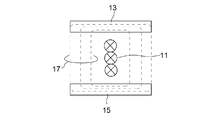
図1を参照すると、発明者が先に提案したコイル部品の一例は、コイル(巻線)11と、コイル11を挟んで互いに対向配置された一対の圧粉コア(高μコア)13,15とを有している。一対の圧粉コア13,15の間、即ち、コイル11の両側には、図示しない注型コア(低μコア)が設けられる。なお、「圧粉コア」は軟磁性合金粉末と結合材を圧縮成型したものであり、「注型コア」は軟磁性合金粉末及びバインダ(樹脂)等を含むスラリーを硬化させたものである。一般に圧粉コアの方が注型コアよりもその透磁率(μ)を高くすることができる。
Referring to FIG. 1, an example of the coil component previously proposed by the inventor is a coil (winding) 11 and a pair of dust cores (high μ cores) 13 and 15 disposed opposite to each other across the
図1に破線で示されるように、コイル11に電流を流すとコイル11の周りを回る磁束17が生じる。磁束17は、高μコアである圧粉コア13,15の内部を通過しようとするため、圧粉コア13,15の両端部には強い磁極N及びSが形成される。換言すると、圧粉コア13及び15の両端部同士の間には各々一方向へ向かう磁界(垂直磁界)が形成される。これにより、注型コアを通過する磁束17は、圧粉コア13の一方の端部付近から圧粉コア15の一方の端部付近へ、また、圧粉コア15の他方の端部付近から圧粉コア13の他方の端部付近へと真っ直ぐに向うよう誘導される。その結果、磁束17はコイル11から離れた経路を真っ直ぐに進むので、磁束17のコイル11へ侵入は抑制される。こうして、磁束17がコイル11に進入することにより生じる渦電流は低減され、交流銅損は低減される。また、たとえ注型コアの途中に磁気ギャップが設けられていたとしても、垂直磁界の働きにより、その磁気ギャップにおける磁束17の漏れを抑制することができる。
As shown by a broken line in FIG. 1, when a current is passed through the
上述した、圧粉コア13,15を用いたことによる交流銅損低減効果は、コイル11の巻回方式によって異なる。即ち、コイル11の巻線として平角線を用いたエッジワイズコイルとフラットワイズコイルとでは、垂直磁界による磁束17の誘導効果に違いが生じる。図2に示されるように、平角線を垂直磁界に沿った方向に巻回したエッジワイズコイルの方が、図3に示されるように、平角線を垂直磁界に直交する方向に巻回したフラットワイズコイルよりも、コイル11内への磁束17の侵入を抑制し、交流銅損を低減することができる。なお、図2及び図3では横方向のコイル11のサイズが異なっているが、これらのサイズは等しいものとする。
The above-described AC copper loss reduction effect due to the use of the
発明者は、図1のような構成を持つコイル部品の低背化の検討を行った。なお、ここでの低背化は、コイル部品の高さをその幅の1/3以下にすること、しかもその高さは30mm以下であることを想定している。図1のようなコイル部品を低背化すると、圧粉コア13,15に形成される強い磁極N,Sが互いに接近し、強い磁界を生じる。その一方、コイル11は、低背化によって磁気抵抗が減少する。その結果、図4に矢印で示されるように、コイル11を通過する磁束17が増加する。なお、図4において、磁極N,Sの文字の大きさは磁界の強さを表している。低背化されたコイル部品では、フラットワイズコイルの使用が望まれる。所定の巻数を有するエッジワイズコイルを低背化するには、巻線の厚みを低減しなければならず、巻回し(作製)が困難になるからである。図5に示されるように、フラットワイズコイルを使用すると、コイル11を通過する磁束17はさらに増加する。コイル11を通過する磁束17は、コイル11の巻線に渦電流を発生させ、交流銅損を増加させる。なお、図6に示されるように、コア全体を注型コア19で構成した場合は、磁束17を誘導する圧粉コアが存在しないため、コイル11を通過する磁束17は比較的多い。
The inventor has studied a reduction in the height of the coil component having the configuration shown in FIG. In addition, the height reduction here assumes that the height of the coil component is 1/3 or less of the width, and that the height is 30 mm or less. When the height of the coil component as shown in FIG. 1 is reduced, the strong magnetic poles N and S formed on the
本発明のコイル部品は、上記問題を解決するため、概略以下のように構成される。即ち、コイル部品は、通電によって磁束を発生させる導体と、その導体の周囲に設けられ、磁束が循環する磁路を形成するコアとを有する。導体は、磁路を含む平面において、四角形の巻窓を形成する断面を有する。コアは、第1透磁率を有する第1コアと、第1透磁率よりも低い第2透磁率を有する第2コアとを有する。第1コアは、磁路を含む平面において、巻窓の一辺全体に接し、その一辺の両端から突き出している。また、第1コアは、接している一辺を含む直線に関して、巻窓の反対側に位置している。第2コアは、磁路を含む平面において、巻窓の第1コアが接している一辺以外の三辺に接している。 In order to solve the above problems, the coil component of the present invention is generally configured as follows. That is, the coil component includes a conductor that generates a magnetic flux when energized and a core that is provided around the conductor and forms a magnetic path through which the magnetic flux circulates. The conductor has a cross section forming a rectangular winding window in a plane including a magnetic path. The core includes a first core having a first magnetic permeability and a second core having a second magnetic permeability lower than the first magnetic permeability. In the plane including the magnetic path, the first core is in contact with the entire side of the winding window and protrudes from both ends of the side. Moreover, the 1st core is located in the other side of a winding window regarding the straight line containing the side which has contact | connected. The second core is in contact with three sides other than the one side with which the first core of the winding window is in contact in the plane including the magnetic path.
(第1の実施の形態)
図7を参照すると、本発明の第1の実施の形態によるコイル部品20は、コイル21と、圧粉コア(第1コア)23と、注型コア(第2コア)25と、これらを収容するケース27とを有している。
(First embodiment)
Referring to FIG. 7, the
コイル21は、その断面が略長方形の平角線(導体)を巻線とするコイルである。平角線として、例えば銅線の周囲を絶縁被膜で覆ったポリアミドイミド線(AIW)などを用いることができる。またコイル21は、その外周面がさらに図示しない絶縁被膜で覆われていてもよい。図7から理解されるように、コイル21は、第1方向(図の上下方向)に沿った軸を持ち、軸に対して直交する方向に沿って巻線を巻回して構成されるフラットワイズコイルである。コイル21は、一対の端面211、213と、これらをつなぐ内周面215及び外周面217を有している。端面の形状は、環状の多角形若しくは円形である。コイル21は、通電によって磁束を発生させる。
The
図7に示されるように、圧粉コア23と注型コア25とは、コイル21の周囲に配置される。詳細には、圧粉コア23は、コイル21の下面211側に配置され、注型コア25は、圧粉コア23及びコイル21の上に配置される。具体的には、コイル21は、圧粉コア23上に配置される。これにより、圧粉コア23は、コイル21の下面211よりも下にのみ存在し、下面211よりも上(上面213側)には存在しない。圧粉コア23は、コイル21の端面211,213の外形よりも大きい外形を有し、コイル21は、圧粉コア23の一面上において、外周面よりも内側に配置される。これにより、圧粉コア23は、コイル21の下面211全体を覆い、コイル21の外周面よりも外側に突き出している。一方、注型コア25は、コイル21の内周面215、外周面217、及び上面213の全部に接し、コイル21を覆っている。ここで、圧粉コア23は、第1透磁率を有し、注型コア25は、第1透磁率よりも低い第2透磁率を有している。換言すると、圧粉コア23は高μコアであり、注型コア25は低μコアである。
As shown in FIG. 7, the
図7から理解されるように、コイル21が発生させた磁束は、主に圧粉コア23と注型コア25の内部を通過する。即ち、圧粉コア23と注型コア25とは、磁束が循環する磁路を形成する。磁束は、圧粉コア23と注型コア25とが形成する磁路内を、コイル21の外周面217側から一方の端面(上面)213側を通って内周面215側へ向かい、コイル21の反対側に出て、内周面215側から他方の端面(下面)211側を通って外周面217側へと循環する。なお、本実施の形態では、圧粉コア23がコイル21の角部(内周面215又は外周面217と端面211,213の各々との境界)を跨いで配置されていない。そのため、磁束の向きが大きく変化するコイル21の角部において、磁束のコイル21への侵入は抑制される。
As understood from FIG. 7, the magnetic flux generated by the
図7に示されるように、ケース27は、底部271と、底部271の周縁から一方向(第1方向)へ突き出す側部273とを有する無蓋のケースである。ケース27は、圧粉コア23を底部271側に向けた状態で、コイル21、圧粉コア23及び注型コア25を収容する。コイル21をケース27に収容した状態で、圧粉コア23は、コイル21と底部271との間に位置し、底部271に接している。本実施の形態では、コイル21と底部271との間に圧粉コア23を配置したことで、コイル21に生じる熱を、圧粉コア23を介して効率的にケース27に伝えることができる。通常、ケース27は、放熱機構等に連結される。
As shown in FIG. 7, the
図7に示されるように、コイル21の軸を含みかつ磁束が循環する磁路を含む平面において、コイル21は二つの断面を有する。これら二つのコイル21の断面はいずれも巻窓を形成する。コイル21が、その外周を覆う絶縁被膜等を有している場合には、その絶縁被膜等の断面も巻窓に含まれる。即ち、巻窓には導体部分のみならずコイル21を構成する絶縁体部分も含まれる。本実施の形態では、周囲に循環する磁束が形成されるコイル21の断面を巻窓と称する。したがって、コイル21が単体の場合、各断面がそれぞれ巻窓を形成する。一方、複数のコイルが重ねられたり、近接配置されたりしている場合は、複数の断面が一つの巻窓を形成することがある。例えば、同一形状の二以上のコイルが互いに軸を一致させて上下に重ねられている場合、上下に重なる二つコイルの断面が一つの巻窓を形成する。つまり、この場合、コイルの断面は四つであるが、形成される巻窓は二つである。また、この場合、圧粉コア23は、二つのコイルのいずれか一方のコイルの二つの端面のうちの一方に接し、他方のコイルには接しない。なお、重ねられたり近接配置されたりした複数のコイルは、互いに接触している必要はなく、それらの間に隙間があってもよい。
As shown in FIG. 7, the
図7に示されるように、本実施の形態では、各巻窓の形状は実質的に四角形である。即ち、各巻窓は、第1方向延びる二つの辺と第2方向に延びる二つの辺とを有している。圧粉コア23は、各巻窓の一辺(コイル21の下面211に対応)全体に接し、その一辺の両端から第2方向に沿って突き出している。また、圧粉コア23は、接している巻窓の一辺を含む直線に関して、巻窓の反対側に位置している。また、注型コア25は、各巻窓の残りの三辺に接している。
As shown in FIG. 7, in the present embodiment, the shape of each winding window is substantially a quadrangle. That is, each winding window has two sides extending in the first direction and two sides extending in the second direction. The
図7から理解されるように、コイル21に電流を流して磁束を発生させると、圧粉コア23には強い磁極N,Sが形成される。圧粉コア23が、各巻窓の一辺の両端よりも外側に延びているからである。形成された磁極N,Sには、対向する強い磁極が存在しない。そのため、注型コア25内に強い垂直磁界は生じない。そのゆえ、コイル21を通過する磁束は、図1に示した構成のコイル部品に比べて低減される。その結果、交流銅損を低減することができる。その一方で、コイル部品20自体の厚みが薄いため、圧粉コア23による磁束の誘導は依然期待できる。これにより、低損失を維持しつつインダクタンスLを向上させることができる。なお、このような効果は、巻窓の圧粉コア23が接している辺の長さをAとし、それに直交する辺の長さをBとしたときのアスペクト比K=A/Bが、0.6より大きいとき、特に1より大きいときに顕著である。よって、コイル21の形状は、K>0.6となるように、望ましくはK>1となるように設定される。
As understood from FIG. 7, strong magnetic poles N and S are formed in the
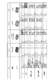
図8を参照すると、本実施の形態によるコイル部品20(No.1)と、図1の構成を持つコイル部品(No.2)と、コア全てを圧粉コアとしたコイル部品(No.3)と、コア全てを注型コアとしたコイル部品(No.4)の各種特性値を有限要素法(FEM)により求めた結果が示されている。図8から理解されるように、本実施の形態によるコイル部品20(No.1)は、図1の構成を持つコイル部品(No.2)に比べて抵抗損失Racが低く、交流銅損も少ない。また、本実施の形態によるコイル部品20(No.1)は、コア全てを圧粉コアとしたコイル部品(No.3)に比べて、インダクタンスLが高く、損失抵抗Racが低い。また、本実施の形態によるコイル部品20(No.1)は、コア全てを注型コアとしたコイル部品(No.4)に比べて損失抵抗Racがやや高いものの、インダクタンスL(0A)は高く、熱抵抗は小さい。 Referring to FIG. 8, the coil component 20 (No. 1) according to the present embodiment, the coil component (No. 2) having the configuration of FIG. ) And various characteristic values of the coil component (No. 4) in which all the cores are cast cores are obtained by the finite element method (FEM). As understood from FIG. 8, the coil component 20 (No. 1) according to the present embodiment has lower resistance loss Rac and AC copper loss than the coil component (No. 2) having the configuration of FIG. Few. In addition, the coil component 20 (No. 1) according to the present embodiment has a higher inductance L and a lower loss resistance Rac than a coil component (No. 3) in which all the cores are powder cores. Further, the coil component 20 (No. 1) according to the present embodiment has a slightly higher loss resistance Rac than the coil component (No. 4) in which all the cores are cast cores, but has a higher inductance L (0A). The thermal resistance is small.
上記実施の形態では、圧粉コア23が、コイル21の下面211全体を覆い、さらに外側に突き出すように配置されているが、本発明はこれに限られない。例えば、EIコアやUIコアのように、コイル21の一部を囲うものであってもよい。少なくとも、図9に示されるコイル部品20Aのように、コイル21の端面(下面)211の一部に接する圧粉コア23Aが配置されていればよい。この場合、圧粉コア23Aは、その長手方向が、コイル21の外周面217における接線方向と直交するように配置される。また、圧粉コア23Aは、その長手方向の端部がいずれもコイル21の内周面215及び外周面217よりも外側に突き出すように配置される。換言すると、圧粉コア23Aは、コイル21が発生する磁束が循環する磁路の一部を形成するように配置される。また、圧粉コア23Aは、コイル21の軸と圧粉コア23Aが形成する磁路とを含む平面において、巻窓の一辺(コイル21の下面211に対応)全体に接し、その一辺の両端からその一辺が延びる方向へ突き出している。さらに、圧粉コア23Aは、接している巻窓の一辺を含む直線に関して、巻窓の反対側に位置している。この場合においても、注型コア25は、圧粉コア23Aが接している巻窓の残りの三辺に接している。このように、コイル21の下面211の一部を覆うように圧粉コア23Aを設けても、一対の圧粉コアを用いた場合に比べて、交流銅損を低減することができる。
In the said embodiment, although the
(第2の実施の形態)
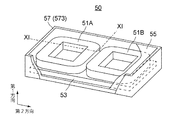
図10を参照すると、本発明の第2の実施の形態によるコイル部品50は、二つのコイル51A,51Bと、圧粉コア53と、注型コア55と、ケース57とを有している。図11を参照すると、コイル部品50は、さらに、コイル51A,51Bの下面を覆うアルミナ板61、コイル51A,51Bの上面、内周面及び外周面を覆う絶縁被膜63、及びコイル51A,51Bの内周側において圧粉コア53上に配置されたギャップ材65を有している。
(Second Embodiment)
Referring to FIG. 10, the
図10及び図11から理解されるように、二つのコイル51A,51Bは、夫々、第1の実施の形態のコイル21と同様に構成されている。即ち、コイル51A,51Bは、互いに同一の構成を有している。コイル51A,51Bの各々は、アルミナ板61と絶縁被膜63によってその周囲を覆われている。また、コイル51A,51Bは、互いに逆方向に電流が流れるように互いに接続されている。コイル51A,51Bは、互いに平行な軸を有し、軸に沿った方向(第1方向)に直交する第2方向に並べて近接配置されている。
As understood from FIGS. 10 and 11, the two
圧粉コア53及び注型コア55は、第1の透磁率及び第2の透磁率をそれぞれ有している。第1の透磁率は第2透磁率よりも高い。圧粉コア53は、アルミナ板61を介してコイル51A,51Bの一対の端面の一方(下面)に接するように配置されている。換言するとコイル51A,51Bは、アルミナ板61を介して圧粉コア53の一面(上面)上に設けられている。コイル51A,51Bの各々の内周側において、圧粉コア53の一面上には、ギャップ材65が配置されている。注型コア55は、コイル51A,51B、アルミナ板61、ギャップ材65を覆うように圧粉コア53上に設けられている。ケース57は、底部571と底部571から一方向(第1方向)へ延びる側部573とを有している。ケース57は、その内部にコイル51A,51B、圧粉コア53及び注型コア55等を収容する。ケース57に収容された状態で、圧粉コア53はコイル51A,51Bとケース57の底部571との間に位置し、底部571に接している。注型コア55は、ケース57内に隙間を生じないように形成されている。
The
図12を参照すると、コイル51A,51Bの軸とコア(圧粉コア53及び注型コア55)が形成する磁路(循環する磁束が通過する磁路)とを含む平面において、コイル51A,51Bは、第2方向に並ぶ四つの断面を有している。図12において、アルミナ板61、絶縁被膜63、ギャップ材65及びケース57は省略されている。また、以下の説明では、アルミナ板61及び絶縁被膜63をも含めてコイル51A又は51Bと称する。コイル51A,51Bの四つの断面は、三つの巻窓を構成する。中央側に位置するコイル51A,51Bの断面は、一つの巻窓を構成し、両側に位置するコイル51A,51bの断面は、それぞれ一つの巻窓を構成する。各巻窓の形状は、実質的に四角形である。
Referring to FIG. 12, in the plane including the axes of the
図12に示されるように、圧粉コア53は、三つの巻窓の各々の一辺(コイル51A,51Bの下面511A,511Bに対応)を含む直線に関して各巻窓(コイル51A,51B)の反対側に位置している。また、圧粉コア53は、各巻窓の一辺(コイル51A又は51Bの下面511A又は511Bに対応)全体に接しており、その一辺の両端から外側(第2方向に沿った方向)へ突き出している。本実施の形態では、圧粉コア53は、第2方向において二つのコイル51A、51Bの両側から外側へ突き出している。換言すると、コイル51A,51Bの軸に沿って見た場合、圧粉コア53の外形は、二つのコイル51A,51Bを合わせた外形よりも大きい。注型コア55は、各巻窓の圧粉コア53が接している一辺を除く残りの三辺に接している。
As shown in FIG. 12, the
コイル51A,51Bに通電することによって発生する磁束のうち、中央に位置する巻窓の周囲を循環する磁束は、一方のコイル51Aの内周面515A側からコイル51A,51Bの上面513A,513B側を通って他方のコイル51Bの内周面515B側へ向かい、他方のコイル51Bの下面511B側に出て、他方のコイル51Bの内周面515B側からコイル51B,51Aの端面511B,511A側を通って一方のコイル51Aの内周面515A側へ戻る。両側に位置する各巻窓の周囲を循環する磁束は、各コイル51A,51Bの外周面517A,517B側から上面513A,513B側を通って内周面515A,515B側へ向かい、コイル51A,51Bの反対側に出て、内周面515A,515B側から下面511A,511B側を通ってコイル51A,51Bの内周面515A,515B側へ戻る。磁束は、圧粉コア53に強い磁極N,Sを発生させる。図11において、磁極の強さは、文字の大きさで表されている。
Of the magnetic flux generated by energizing the
本実施の形態においても、圧粉コア53に形成された強い磁極N,Sには、対向する強い磁極が存在しない。このため、注型コア55内に強い垂直磁界は生じない。その結果、コイル51A,51Bへの磁束の侵入は抑制され、交流銅損を低減することができる。その一方で、コイル部品50自体の厚みが薄い(K>0.6)ため、圧粉コア53による磁束の誘導が期待できる。これにより漏れ磁束を低減することができる。
Also in this embodiment, the strong magnetic poles N and S formed on the
上記第2の実施の形態では、軸方向に沿ってみた場合に、圧粉コア53の外形がコイル51A,51Bを合わせた外形よりも大きく、第2方向において、圧粉コア53がコイル51A,51Bの両側から突き出しているが、本発明はこれに限られない。圧粉コア53は、いずれか一つの巻窓に接して設けられていればよく、その接している一辺の両端から外側に突き出していればよい。例えば、図13に示されるコイル部品50Aのように、圧粉コア53は、中央に位置する巻窓に接し、その両側から突き出していればよい。図13の例では、圧粉コア53は、両側に位置する巻窓にも接しているが、両側に位置する巻窓に接していなくてもよい。
In the said 2nd Embodiment, when it sees along an axial direction, the external shape of the
また、上記第2の実施の形態では、コイル部品が二つのコイル51A,51Bを有している場合について説明したが、本発明はこれに限られない。例えば、二つのコイル51A,51Bの代わりに、複数のコイルを第1方向に層状に重ねた(近接配置された)二組のコイルを第2方向に近接配置したものであってもよい。この場合、二組のコイルが形成する三つの巻窓のうち、少なくとも中央の巻窓の一辺に圧粉コア53が接していればよい。また、この場合、圧粉コア53は、各組に含まれるいずれか一つのコイルの一方の端面に接し、他のコイルには接しない。
Moreover, although the said 2nd Embodiment demonstrated the case where a coil component had the two
(第3の実施の形態)
図14を参照すると、本発明の第3の実施の形態に係るコイル部品70は、コイル71と、圧粉コア73と、注型コア75とを有している。コイル71、圧粉コア73及び注型コア75は、第1の実施の形態のケース27と同様のケース(図示せず)に収容されている。また、コイル71は、第1の実施の形態のコイル21と同様に構成されている。即ち、コイル71は、その断面がほぼ長方形の平角線をフラットワイズ方式で巻き回したフラットワイズコイルである。コイル71は、その外周が図示しない絶縁皮膜で覆われたものであってもよい。圧粉コア73及び注型コア75は、第1の透磁率及び第2の透磁率をそれぞれ有している。第1の透磁率は第2透磁率よりも高い。圧粉コア73は、コイル71の内周側に配置され、コイル71の両端面711,713から外側へ突き出している。圧粉コア73の一端は、図示しないケースの底部に接している。注型コア75は、ケース内に隙間を生じないように形成されている。
(Third embodiment)
Referring to FIG. 14, a
図14に示されるように、コイル71の軸とコア(圧粉コア73及び注型コア75)が形成する磁路(循環する磁束が通過する磁路)とを含む平面において、コイル71は、第2方向に並ぶ二つの四角形の巻窓(断面)を有している。圧粉コア73は、各巻窓の一辺(コイル71の内周面に対応)を含む直線に関してその巻窓の反対側に位置している。また、圧粉コア73は、各巻窓の一辺(コイル71の内周面715対応)全体に接しており、その一辺の両端から外側(第1方向に沿った方向)へ突き出している。本実施の形態においても、圧粉コア73が接している巻窓の一辺の長さをA、それに直交する巻窓の辺の長さをBとするときのアスペクト比K=A/Bは、0.6より大きく、望ましくは1より大きい。
As shown in FIG. 14, in the plane including the axis of the
コイル71に通電することによって発生する磁束は、二つの巻窓のそれぞれの周囲を循環する。即ち、磁束は、コイル71の上面713側において内周面715側からコイル71の外周面717側へ向かい、下面711側へ回る。それから、磁束は、下面711側において、外周面717側から内周面715側へ向かい、上面713側へ回る。このとき、磁束は、圧粉コア73に強い磁極N,Sを発生させる。本実施の形態においても、圧粉コア73に形成された強い磁極N,Sには、対向する強い磁極が存在しない。このため、注型コア75内に強い垂直磁界は生じない。その結果、コイル71への磁束の侵入は抑制され、交流銅損を低減することができる。その一方で、コイル部品70自体の厚みが薄い(K>0.6)ため、圧粉コア73による磁束の誘導が期待できる。これにより漏れ磁束を低減することができる。
Magnetic flux generated by energizing the
上記第3の実施の形態では、コイル部品が、単一のコイル71を有する場合について説明したが、本発明はこれに限られない。例えば、コイル部品は、複数のコイルを第1方向に層状に重ねた(近接配置された)コイルを有していてもよい。この場合、圧粉コア73は、複数のコイルが形成する2つの巻窓の対向する二辺のいずれか一方に接していればよい。また、この場合、圧粉コア73は、複数のコイルの全ての内周面(全部または一部)又は外周面(全部または一部)に接する。また、コイル部品は、第1方向に直交する第2方向に並べた二つ又は二組のコイルを有していてもよい。この場合、コイルは、軸と巡回する磁束とを含む平面において、第2方向に並ぶ四つ(二対)の巻窓を形成する。圧粉コア73は、各対をなす二つの巻窓の対向する二辺に接する。換言すると、圧粉コア73は各(組の)コイルの内周面に接するように内周側に配置される。巻窓の他の辺には、注型コア75が接する。
Although the case where the coil component has a
以上、本発明についていくつかの実施の形態を説明したが、本発明は上記実施の形態に限られない。例えば、上記各実施の形態では、磁束が循環する磁路を構成するコアは、連続していたが、磁路の途中に磁気ギャップ(エアギャップやギャップ材)を配置してもよい。また、上記各実施の形態では、圧粉コア及び注型コアはそれぞれ単体であったが、複数の分割された部分からなってもよい。 As mentioned above, although several embodiment was described about this invention, this invention is not restricted to the said embodiment. For example, in each of the above embodiments, the core constituting the magnetic path through which the magnetic flux circulates is continuous, but a magnetic gap (air gap or gap material) may be disposed in the middle of the magnetic path. In each of the above embodiments, the dust core and the casting core are each a single unit, but may be composed of a plurality of divided portions.
11 コイル(巻線)
13,15 圧粉コア(高μコア)
17 磁束
19 注型コア
20 コイル部品
21 コイル
211 端面(下面)
213 端面(上面)
215 内周面
217 外周面
23,23A 圧粉コア(第1コア)
25 注型コア(第2コア)
27 ケース
271 底部
273 側部
50,50A コイル部品
51A,51B コイル
511A,511B 端面(下面)
513A,513B 端面(上面)
515A,515B 内周面
517A,517B 外周面
53 圧粉コア
55 注型コア
57 ケース
571 底部
573 側部
61 アルミナ板
63 絶縁被膜
65 ギャップ材
70 コイル部品
71 コイル
711 端面(下面)
713 端面(上面)
715 内周面
717 外周面
73 圧粉コア
75 注型コア
11 Coil (winding)
13, 15 Powder core (high μ core)
17
213 End face (upper surface)
215 Inner
25 Casting core (second core)
27
513A, 513B End face (upper surface)
515A, 515B Inner
713 End face (upper surface)
715 inner
Claims (14)
前記導体の周囲に設けられ、前記磁束が循環する磁路を形成するコアと、
を有するコイル部品であって、
前記導体は、前記磁路を含む平面において、四角形の巻窓を形成する断面を有し、
前記コアは、第1透磁率を有する第1コアと、前記第1透磁率よりも低い第2透磁率を有する第2コアとを有し、
前記第1コアは、前記平面において、前記巻窓の一辺全体に接し、当該一辺の両端から当該一辺の延びる方向へ突き出し、かつ前記一辺を含む直線に関して前記巻窓の反対側に位置しており、
前記第2コアは、前記平面において、前記巻窓の前記一辺以外の三辺に接している
コイル部品。 A conductor that generates magnetic flux when energized;
A core provided around the conductor and forming a magnetic path through which the magnetic flux circulates;
A coil component comprising:
The conductor has a cross section forming a rectangular winding window in a plane including the magnetic path;
The core has a first core having a first magnetic permeability and a second core having a second magnetic permeability lower than the first magnetic permeability,
The first core is in contact with the entire side of the winding window in the plane, protrudes from both ends of the one side in a direction in which the one side extends, and is positioned on the opposite side of the winding window with respect to a straight line including the one side. ,
The second core is a coil component in contact with three sides other than the one side of the winding window in the plane.
前記導体は、第1方向に沿った軸を有する一つ以上のコイルを構成している巻線であり、
前記コイルは、前記平面において、前記巻窓を二つ以上形成するものであり、
前記第1コアは、前記平面において、前記巻窓のうちの少なくとも一つの巻窓に接している
コイル部品。 The coil component of claim 1,
The conductor is a winding constituting one or more coils having an axis along a first direction;
The coil forms two or more winding windows in the plane,
The first core is a coil component in contact with at least one of the winding windows in the plane.
前記平面は前記軸を含むものであり、
前記コイルは、前記平面において、前記巻窓を三つ形成するものであり、
前記巻窓は、前記第1方向に直交する第2方向に並んでおり、
前記第1コアは、前記平面において、前記巻窓のうち少なくとも中央に位置する巻窓の前記第2方向へ延びる一辺に接している
コイル部品。 The coil component according to claim 2,
The plane includes the axis;
The coil forms three winding windows in the plane,
The winding windows are arranged in a second direction orthogonal to the first direction,
The first core is a coil component in contact with one side extending in the second direction of a winding window located at least in the center of the winding window in the plane.
前記第1コアは、前記平面において、前記巻窓のうち両側に位置する巻窓の夫々の一辺全体に接している
コイル部品。 The coil component according to claim 3,
The first core is a coil component in contact with the entire one side of each of the winding windows located on both sides of the winding window in the plane.
前記第1コアは、前記平面において、両側に位置する前記巻窓の夫々の端部から外側へ突き出している
コイル部品。 The coil component according to claim 4,
The first core is a coil component that protrudes outward from each end portion of the winding window located on both sides in the plane.
前記コイルは、前記第1方向に直交する第2方向に近接配置された二つ又は二組のコイルである
コイル部品。 The coil component according to any one of claims 3 to 5,
The coil component is a coil component which is two or two sets of coils arranged close to each other in a second direction orthogonal to the first direction.
前記コイルは、前記平面において、前記巻窓を二つの形成するものであり、
前記巻窓は前記第1方向に直交する第2方向に並んでおり、
前記第1コアは、前記巻窓のうち少なくとも一方の巻窓の前記第2方向へ延びる一辺に接している
コイル部品。 The coil component according to claim 2,
The coil forms two winding windows in the plane,
The winding windows are arranged in a second direction orthogonal to the first direction,
The first core is a coil component in contact with one side extending in the second direction of at least one of the winding windows.
前記コイルは、前記平面において、前記巻窓を二つ形成するものであり、
前記第1コアは、前記巻窓の互いに対向する二つの辺に接している
コイル部品。 The coil component according to claim 2,
The coil forms two of the winding windows in the plane,
The first core is a coil component in contact with two opposite sides of the winding window.
前記コイルは、単一のコイル又は前記第1の方向に近接配置された複数のコイルである
コイル部品。 The coil component according to claim 7 or 8,
The coil component is a single coil or a plurality of coils arranged close to each other in the first direction.
前記平面は前記軸を含むものであり、
前記コイルは、前記平面において、前記巻窓を四つ形成するものであり、
前記巻窓は、前記第1方向に直交する第2方向に並んで二つの対をなすものであり、
前記第1コアは、前記平面において、各対をなす前記巻窓の互いに対向する二つの辺に接している
コイル部品。 The coil component according to claim 2,
The plane includes the axis;
The coil forms four winding windows in the plane,
The winding window forms two pairs side by side in a second direction orthogonal to the first direction,
The first core is a coil component in contact with two opposite sides of the pair of winding windows in the plane in the plane.
前記第1コアが接する前記巻窓の一辺の長さをAとし、それに直交する前記巻窓の他辺の長さをBとしたとき、A/B>0.6である
コイル部品。 The coil component according to any one of claims 1 to 10,
A coil component in which A / B> 0.6, where A is the length of one side of the winding window in contact with the first core, and B is the length of the other side of the winding window that is orthogonal thereto.
A/B>1である
コイル部品。 The coil component according to claim 11,
Coil parts with A / B> 1.
前記コイルは、平角線をフラットワイズ方式で巻回したコイルである
コイル部品。 The coil component according to any one of claims 1 to 12,
The coil is a coil component formed by winding a flat wire in a flat-wise manner.
底部と、前記底部から一方向へ延びる側部とを有し、前記コイル及び前記コアを収容するケースをさらに有し、
前記第1コアは、前記底部と接してしている
コイル部品。 The coil component according to any one of claims 1 to 13,
A bottom portion and a side portion extending in one direction from the bottom portion, and further comprising a case for accommodating the coil and the core;
The first core is a coil component in contact with the bottom.
Priority Applications (1)
| Application Number | Priority Date | Filing Date | Title |
|---|---|---|---|
| JP2016025060A JP6673711B2 (en) | 2016-02-12 | 2016-02-12 | Coil parts |
Applications Claiming Priority (1)
| Application Number | Priority Date | Filing Date | Title |
|---|---|---|---|
| JP2016025060A JP6673711B2 (en) | 2016-02-12 | 2016-02-12 | Coil parts |
Publications (2)
| Publication Number | Publication Date |
|---|---|
| JP2017143220A true JP2017143220A (en) | 2017-08-17 |
| JP6673711B2 JP6673711B2 (en) | 2020-03-25 |
Family
ID=59628763
Family Applications (1)
| Application Number | Title | Priority Date | Filing Date |
|---|---|---|---|
| JP2016025060A Active JP6673711B2 (en) | 2016-02-12 | 2016-02-12 | Coil parts |
Country Status (1)
| Country | Link |
|---|---|
| JP (1) | JP6673711B2 (en) |
Cited By (2)
| Publication number | Priority date | Publication date | Assignee | Title |
|---|---|---|---|---|
| US10546682B2 (en) | 2018-01-17 | 2020-01-28 | Tokin Corporation | Reactor and step-up circuit |
| WO2022176053A1 (en) * | 2021-02-17 | 2022-08-25 | 株式会社トーキン | Coil component |
Citations (5)
| Publication number | Priority date | Publication date | Assignee | Title |
|---|---|---|---|---|
| JPS55140217A (en) * | 1979-03-09 | 1980-11-01 | Gen Electric | Induction circuit component and method of fabricating same |
| JP2000294429A (en) * | 1999-04-09 | 2000-10-20 | Hitachi Ferrite Electronics Ltd | Compound magnetic core |
| JP2003168610A (en) * | 2001-11-29 | 2003-06-13 | Toko Inc | Inductance element |
| WO2013073384A1 (en) * | 2011-11-14 | 2013-05-23 | 住友電気工業株式会社 | Reactor, molded coil, converter, and power conversion device |
| JP2014216511A (en) * | 2013-04-26 | 2014-11-17 | トヨタ自動車株式会社 | Reactor |
-
2016
- 2016-02-12 JP JP2016025060A patent/JP6673711B2/en active Active
Patent Citations (5)
| Publication number | Priority date | Publication date | Assignee | Title |
|---|---|---|---|---|
| JPS55140217A (en) * | 1979-03-09 | 1980-11-01 | Gen Electric | Induction circuit component and method of fabricating same |
| JP2000294429A (en) * | 1999-04-09 | 2000-10-20 | Hitachi Ferrite Electronics Ltd | Compound magnetic core |
| JP2003168610A (en) * | 2001-11-29 | 2003-06-13 | Toko Inc | Inductance element |
| WO2013073384A1 (en) * | 2011-11-14 | 2013-05-23 | 住友電気工業株式会社 | Reactor, molded coil, converter, and power conversion device |
| JP2014216511A (en) * | 2013-04-26 | 2014-11-17 | トヨタ自動車株式会社 | Reactor |
Cited By (4)
| Publication number | Priority date | Publication date | Assignee | Title |
|---|---|---|---|---|
| US10546682B2 (en) | 2018-01-17 | 2020-01-28 | Tokin Corporation | Reactor and step-up circuit |
| WO2022176053A1 (en) * | 2021-02-17 | 2022-08-25 | 株式会社トーキン | Coil component |
| JPWO2022176053A1 (en) * | 2021-02-17 | 2022-08-25 | ||
| JP7614320B2 (en) | 2021-02-17 | 2025-01-15 | 株式会社トーキン | Coil parts |
Also Published As
| Publication number | Publication date |
|---|---|
| JP6673711B2 (en) | 2020-03-25 |
Similar Documents
| Publication | Publication Date | Title |
|---|---|---|
| EP1496596A1 (en) | Stator of rotating electric motor | |
| CN104115243A (en) | Transformer | |
| CN104487337B (en) | Three-Phase Resolver with Free Link Flux | |
| JP5416078B2 (en) | Magnetic component and method of manufacturing magnetic component | |
| EP2787515B1 (en) | Inductor gap spacer | |
| JP7063579B2 (en) | Transformers and coil bobbins | |
| JPWO2018207897A1 (en) | Polyphase claw pole motor and stator constituting the polyphase claw pole motor | |
| JP6673711B2 (en) | Coil parts | |
| JP6084433B2 (en) | Reactor | |
| JP6143076B2 (en) | Superconducting rotating electrical machine stator | |
| US2483159A (en) | Magnetic core | |
| JP6631722B2 (en) | Inductor | |
| KR102507790B1 (en) | coil parts | |
| JP2016051873A (en) | Core structure, interleave choke coil and transformer | |
| CN106796841B (en) | The magnetic core array of rotary transformer | |
| JP6912399B2 (en) | Coil parts, choke coils and reactors | |
| JP2021019104A (en) | Reactor device | |
| JPH0362607A (en) | Filter | |
| JP2011188546A (en) | Voice coil motor | |
| CN119361303A (en) | Toroidal core assembly with isotropic magnetic bridges | |
| CN107430928A (en) | Reactor | |
| JP3778284B2 (en) | Composite voice coil linear motor | |
| JP5971923B2 (en) | Amorphous iron core transformer | |
| JP6359244B2 (en) | Reactor | |
| JP2016032077A (en) | Transformer for gas insulated instrument and method for manufacturing the same |
Legal Events
| Date | Code | Title | Description |
|---|---|---|---|
| A621 | Written request for application examination |
Free format text: JAPANESE INTERMEDIATE CODE: A621 Effective date: 20181015 |
|
| A977 | Report on retrieval |
Free format text: JAPANESE INTERMEDIATE CODE: A971007 Effective date: 20190624 |
|
| A131 | Notification of reasons for refusal |
Free format text: JAPANESE INTERMEDIATE CODE: A131 Effective date: 20190710 |
|
| A521 | Request for written amendment filed |
Free format text: JAPANESE INTERMEDIATE CODE: A523 Effective date: 20190903 |
|
| A131 | Notification of reasons for refusal |
Free format text: JAPANESE INTERMEDIATE CODE: A131 Effective date: 20200122 |
|
| A521 | Request for written amendment filed |
Free format text: JAPANESE INTERMEDIATE CODE: A523 Effective date: 20200205 |
|
| TRDD | Decision of grant or rejection written | ||
| A01 | Written decision to grant a patent or to grant a registration (utility model) |
Free format text: JAPANESE INTERMEDIATE CODE: A01 Effective date: 20200226 |
|
| A61 | First payment of annual fees (during grant procedure) |
Free format text: JAPANESE INTERMEDIATE CODE: A61 Effective date: 20200305 |
|
| R150 | Certificate of patent or registration of utility model |
Ref document number: 6673711 Country of ref document: JP Free format text: JAPANESE INTERMEDIATE CODE: R150 |
|
| R250 | Receipt of annual fees |
Free format text: JAPANESE INTERMEDIATE CODE: R250 |
|
| R250 | Receipt of annual fees |
Free format text: JAPANESE INTERMEDIATE CODE: R250 |
|
| S531 | Written request for registration of change of domicile |
Free format text: JAPANESE INTERMEDIATE CODE: R313531 |
|
| R350 | Written notification of registration of transfer |
Free format text: JAPANESE INTERMEDIATE CODE: R350 |
|
| R250 | Receipt of annual fees |
Free format text: JAPANESE INTERMEDIATE CODE: R250 |
|
| R250 | Receipt of annual fees |
Free format text: JAPANESE INTERMEDIATE CODE: R250 |