JP2017144660A - Liquid discharge head, liquid discharge unit and device for discharging liquid - Google Patents
Liquid discharge head, liquid discharge unit and device for discharging liquid Download PDFInfo
- Publication number
- JP2017144660A JP2017144660A JP2016029243A JP2016029243A JP2017144660A JP 2017144660 A JP2017144660 A JP 2017144660A JP 2016029243 A JP2016029243 A JP 2016029243A JP 2016029243 A JP2016029243 A JP 2016029243A JP 2017144660 A JP2017144660 A JP 2017144660A
- Authority
- JP
- Japan
- Prior art keywords
- liquid
- nozzle
- liquid discharge
- discharge head
- individual
- Prior art date
- Legal status (The legal status is an assumption and is not a legal conclusion. Google has not performed a legal analysis and makes no representation as to the accuracy of the status listed.)
- Granted
Links
Images





Landscapes
- Ink Jet (AREA)
- Particle Formation And Scattering Control In Inkjet Printers (AREA)
Abstract
Description
本発明は液体吐出ヘッド、液体吐出ユニット、液体を吐出する装置に関する。 The present invention relates to a liquid discharge head, a liquid discharge unit, and an apparatus for discharging liquid.
液体を吐出する液体吐出ヘッド(液滴吐出ヘッド)として、個別液室に供給された液体の内の吐出されなかった液体を循環流路を介して循環させることで、個別液室内に混入した気泡の排出性の向上及び液体の特性変化の抑制を図る循環型ヘッドが知られている。 Bubbles mixed in the individual liquid chamber by circulating the liquid that was not discharged among the liquid supplied to the individual liquid chamber through the circulation channel as a liquid discharge head (droplet discharge head) that discharges the liquid Circulating heads that improve the discharge performance of the liquid and suppress the change in the characteristics of the liquid are known.
例えば、インク導入口からインクが供給されるインク供給流路と、インク排出口にインクを排出するインク排出流路と、インク供給流路とインク排出流路とを連通し、インクを吐出するノズルを有するインク室と、インク室の振動板を変位させ、インク室内のインクに圧力を加える圧電アクチュエータとを備えるものが知られている(特許文献1)。 For example, an ink supply channel that supplies ink from an ink introduction port, an ink discharge channel that discharges ink to an ink discharge port, and a nozzle that discharges ink by connecting the ink supply channel and the ink discharge channel There is known an ink chamber having an ink chamber and a piezoelectric actuator that displaces a vibration plate of the ink chamber and applies pressure to the ink in the ink chamber (Patent Document 1).
しかしながら、液体を循環させる構成にあっても、個別液室を完全に塞ぐような大きな気泡が混入、発生した場合には、循環流路から気泡を排出することが困難になるという課題がある。 However, even in the configuration in which the liquid is circulated, there is a problem that it is difficult to discharge the bubbles from the circulation flow path when large bubbles that completely block the individual liquid chamber are mixed and generated.
本発明は上記の課題に鑑みてなされたものであり、気泡排出性を向上することを目的とする。 This invention is made | formed in view of said subject, and aims at improving bubble discharge property.
上記の課題を解決するため、本発明に係る液体吐出ヘッドは、
液体を吐出するノズルと、
前記ノズルに通じる個別液室と、
前記ノズルと前記個別液室とを通じるノズル連通路と、
前記ノズル連通路を介して前記個別液室に通じる循環流路と、を有し、
前記ノズル連通路の入口部分に、気泡を微細化する微細化手段が配置されている
構成とした。
In order to solve the above-described problem, a liquid discharge head according to the present invention includes:
A nozzle for discharging liquid;
An individual liquid chamber leading to the nozzle;
A nozzle communication path through the nozzle and the individual liquid chamber;
A circulation channel that leads to the individual liquid chamber via the nozzle communication path,
The micronization means for micronizing bubbles is arranged at the inlet portion of the nozzle communication path.
本発明によれば、気泡排出性を向上することができる。 According to the present invention, the bubble discharge property can be improved.
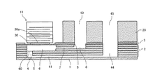
以下、本発明の実施形態について添付図面を参照して説明する。本発明の第1実施形態に係る液体吐出ヘッドの一例について図1ないし図3を参照して説明する。図1は同液体吐出ヘッドの外観斜視説明図、図2は同ヘッドのノズル配列方向と直交する方向(液室長手方向)の断面説明図、図3は同ヘッドの微細化手段の平面説明図である。 Embodiments of the present invention will be described below with reference to the accompanying drawings. An example of the liquid discharge head according to the first embodiment of the present invention will be described with reference to FIGS. 1 is an external perspective view of the liquid ejection head, FIG. 2 is a cross-sectional explanatory view in a direction (liquid chamber longitudinal direction) orthogonal to the nozzle arrangement direction of the head, and FIG. It is.
この液体吐出ヘッドは、ノズル板1と、流路板2と、壁面部材としての振動板3とを積層接合している。そして、振動板3を変位させる圧電アクチュエータ11と、共通液室部材としてのフレーム部材20、カバー21とを備えている。
In the liquid discharge head, a
ノズル板1は、液体を吐出する複数のノズル4を有している。ここでは、複数のノズル4を配列したノズル列を二列有しているが、一列のノズル列に含まれるノズル4のみを図示している。
The
流路板2は、ノズル4にノズル連通路5を介して通じる個別液室6、個別液室6に通じる供給流路側流体抵抗部7、供給流路側流体抵抗部7に通じる液導入部8となる貫通穴や溝部を形成している。ノズル連通路5は、ノズル4と個別液室6にそれぞれ連なって通じる流路である。また、供給流路側流体抵抗部7及び液導入部8が液体供給流路を構成している。なお、ここでは、流路板2は複数枚の板状部材を積層して構成しているが、これに限るものではない。
The
振動板3は、流路板2の個別液室6の壁面を形成する変形可能な振動領域30を有する。
The
そして、この振動板3の個別液室6とは反対側に、振動板3を変形させる駆動手段(アクチュエータ手段、圧力発生手段)としての電気機械変換素子を含む圧電アクチュエータ11を配置している。
A
この圧電アクチュエータ11は、ノズル配列方向に沿って所定の間隔で配置された所要数の柱状の圧電素子(圧電柱)12を有し、圧電素子12は振動領域30の凸部30aに接合されている。
The
フレーム部材20は、ヘッドタンクや液体カートリッジから液体が供給される共通液室10が形成されている。
The
また、流路板2は、個別液室6と反対側であるノズル板1側に、ノズル連通路5に通じる循環流路41となる溝部と、循環流路41が通じる通路44となる貫通穴とを有し、通路44はフレーム部材20に形成された循環共通液室45に通じている。
Further, the
そして、フレーム部材20には、共通液室10に通じる供給ポート23と、循環共通液室45に通じる循環ポート(排出ポート)46がそれぞれ設けられている。
The
このように構成した液体吐出ヘッドにおいては、例えば圧電素子12に与える電圧を基準電位から下げることによって圧電素子12が収縮し、振動板3の振動領域30が引かれて個別液室6の容積が膨張することで、個別液室6内に液体が流入する。
In the liquid discharge head configured as described above, for example, by lowering the voltage applied to the
その後、圧電素子12に印加する電圧を上げて圧電素子12を積層方向に伸長させ、振動板3をノズル4に向かう方向に変形させて個別液室6の容積を収縮させることにより、個別液室6内の液体が加圧され、ノズル4から液体が吐出される。
Thereafter, the voltage applied to the
そして、圧電素子12に与える電圧を基準電位に戻すことによって振動板3の振動領域30が初期位置に復元し、個別液室6が膨張して負圧が発生するので、このとき、共通液室10から個別液室6内に液体が充填される。そこで、ノズル4のメニスカス面の振動が減衰して安定した後、次の吐出のための動作に移行する。
Then, by returning the voltage applied to the
なお、このヘッドの駆動方法については上記の例(引き−押し打ち)に限るものではなく、駆動波形の与えた方によって引き打ちや押し打ちなどを行なうこともできる。 Note that the driving method of the head is not limited to the above example (pulling-pushing), and it is also possible to perform striking or pushing depending on the direction to which the driving waveform is given.
そして、本実施形態においては、ノズル連通路5の個別液室6側の入口部分に気泡を微細化する微細化手段60を設けている。微細化手段60には、図3に示すように、複数の貫通孔61が設けられている。この貫通孔61の開口面積はノズル板1の液体吐出面におけるノズル4の最小開口面積よりも小さい。
And in this embodiment, the refinement | miniaturization means 60 which refine | miniaturizes a bubble is provided in the entrance part by the side of the separate
このように微細化手段60を設けることで、図4(a)に示すように、個別液室6内にノズル連通路5の開口面積よりも大きな径の気泡300が混入、発生した場合でも、図4(b)に示すように、気泡300が微細化手段60の貫通孔61を通過することで微細な気泡301に分割される。
By providing the
微細化された気泡301はノズル連通路5を完全に塞ぐことがなく、循環流路41を通じて循環共通液室45側に排出することができる。
The
これにより、気泡排出性を向上することができる。 Thereby, bubble discharge property can be improved.
次に、本発明の第2実施形態に係る液体吐出ヘッドについて図5を参照して説明する。図5は同ヘッドのノズル配列方向と直交する方向(液室長手方向)の断面説明図である。 Next, a liquid ejection head according to a second embodiment of the present invention will be described with reference to FIG. FIG. 5 is a cross-sectional explanatory view in a direction (liquid chamber longitudinal direction) orthogonal to the nozzle arrangement direction of the head.
本実施形態では、ノズル4は、個別液室6における液体の流れの方向に液体を吐出する位置に配置されている。
In the present embodiment, the
そして、個別液室6のノズル4側の側壁面に循環流路41の開口部を開口させている。
And the opening part of the
ここで、循環流路41の入口部分に気泡を微細化する微細化手段60を配置している。
Here, a refining means 60 for refining bubbles is arranged at the inlet portion of the
このように構成したので、気泡を微細化して循環流路41に送り込むことができ、循環流路41の入口部分を気泡が塞いで排出できなくなる事態を防止でき、気泡排出性を向上できる。
Since it comprised in this way, a bubble can be refined | miniaturized and it can send in to the
次に、本発明の第3実施形態に係る液体吐出ヘッドについて図6を参照して説明する。図6は同ヘッドのノズル配列方向と直交する方向(液室長手方向)の断面説明図である。 Next, a liquid ejection head according to a third embodiment of the invention will be described with reference to FIG. FIG. 6 is a cross-sectional explanatory view in a direction (liquid chamber longitudinal direction) orthogonal to the nozzle arrangement direction of the head.
本実施形態では、第1実施形態において、共通液室10から液導入部8に通じる個別液室6の上流側である供給口9に異物を除去するフィルタ部90を配置している。そして、フィルタ部90のフィルタ孔91の開口面積は、微細化手段6の貫通孔61の開口面積よりも小さくしている。
In the present embodiment, in the first embodiment, the
これにより、異物が微細化手段6の貫通孔61を塞ぐことを抑制でき、安定した吐出を行うことができる。
Thereby, it can suppress that a foreign material block | closes the through-
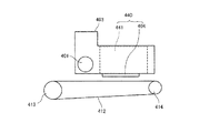
次に、本発明に係る液体を吐出する装置の一例について図7及び図8を参照して説明する。図7は同装置の要部平面説明図、図8は同装置の要部側面説明図である。 Next, an example of an apparatus for ejecting liquid according to the present invention will be described with reference to FIGS. FIG. 7 is an explanatory plan view of the main part of the apparatus, and FIG. 8 is an explanatory side view of the main part of the apparatus.
この装置は、シリアル型装置であり、主走査移動機構493によって、キャリッジ403は主走査方向に往復移動する。主走査移動機構493は、ガイド部材401、主走査モータ405、タイミングベルト408等を含む。ガイド部材401は、左右の側板491A、491Bに架け渡されてキャリッジ403を移動可能に保持している。そして、主走査モータ405によって、駆動プーリ406と従動プーリ407間に架け渡したタイミングベルト408を介して、キャリッジ403は主走査方向に往復移動される。
This apparatus is a serial type apparatus, and the
このキャリッジ403には、本発明に係る液体吐出ヘッド404及びヘッドタンク441を一体にした液体吐出ユニット440を搭載している。液体吐出ユニット440の液体吐出ヘッド404は、例えば、イエロー(Y)、シアン(C)、マゼンタ(M)、ブラック(K)の各色の液体を吐出する。また、液体吐出ヘッド404は、複数のノズルからなるノズル列を主走査方向と直交する副走査方向に配置し、吐出方向を下方に向けて装着している。
A
液体吐出ヘッド404の外部に貯留されている液体を液体吐出ヘッド404に供給するための供給機構494により、ヘッドタンク441には、液体カートリッジ450に貯留されている液体が供給される。
The liquid stored in the
供給機構494は、液体カートリッジ450を装着する充填部であるカートリッジホルダ451、チューブ456、送液ポンプを含む送液ユニット452等で構成される。液体カートリッジ450はカートリッジホルダ451に着脱可能に装着される。ヘッドタンク441には、チューブ456を介して送液ユニット452によって、液体カートリッジ450から液体が送液される。
The
この装置は、用紙410を搬送するための搬送機構495を備えている。搬送機構495は、搬送手段である搬送ベルト412、搬送ベルト412を駆動するための副走査モータ416を含む。
This apparatus includes a
搬送ベルト412は用紙410を吸着して液体吐出ヘッド404に対向する位置で搬送する。この搬送ベルト412は、無端状ベルトであり、搬送ローラ413と、テンションローラ414との間に掛け渡されている。吸着は静電吸着、あるいは、エアー吸引などで行うことができる。
The
そして、搬送ベルト412は、副走査モータ416によってタイミングベルト417及びタイミングプーリ418を介して搬送ローラ413が回転駆動されることによって、副走査方向に周回移動する。
The
さらに、キャリッジ403の主走査方向の一方側には搬送ベルト412の側方に液体吐出ヘッド404の維持回復を行う維持回復機構420が配置されている。
Further, on one side of the
維持回復機構420は、例えば液体吐出ヘッド404のノズル面(ノズルが形成された面)をキャッピングするキャップ部材421、ノズル面を払拭するワイパ部材422などで構成されている。
The maintenance /
主走査移動機構493、供給機構494、維持回復機構420、搬送機構495は、側板491A,491B、背板491Cを含む筐体に取り付けられている。
The main
このように構成したこの装置においては、用紙410が搬送ベルト412上に給紙されて吸着され、搬送ベルト412の周回移動によって用紙410が副走査方向に搬送される。
In this apparatus configured as described above, the
そこで、キャリッジ403を主走査方向に移動させながら画像信号に応じて液体吐出ヘッド404を駆動することにより、停止している用紙410に液体を吐出して画像を形成
する。
Therefore, the
このように、この装置では、本発明に係る液体吐出ヘッドを備えているので、高画質画像を安定して形成することができる。 Thus, since this apparatus includes the liquid ejection head according to the present invention, a high-quality image can be stably formed.
次に、本発明に係る液体吐出ユニットの他の例について図9を参照して説明する。図9は同ユニットの要部平面説明図である。 Next, another example of the liquid discharge unit according to the present invention will be described with reference to FIG. FIG. 9 is an explanatory plan view of the main part of the unit.
この液体吐出ユニットは、前記液体を吐出する装置を構成している部材のうち、側板491A、491B及び背板491Cで構成される筐体部分と、主走査移動機構493と、キャリッジ403と、液体吐出ヘッド404で構成されている。
The liquid discharge unit includes a casing portion composed of
なお、この液体吐出ユニットの例えば側板491Bに、前述した維持回復機構420、及び供給機構494の少なくともいずれかを更に取り付けた液体吐出ユニットを構成することもできる。
Note that a liquid discharge unit in which at least one of the above-described maintenance and
次に、本発明に係る液体吐出ユニットの更に他の例について図10を参照して説明する。図10は同ユニットの正面説明図である。 Next, still another example of the liquid discharge unit according to the present invention will be described with reference to FIG. FIG. 10 is an explanatory front view of the unit.
この液体吐出ユニットは、流路部品444が取付けられた液体吐出ヘッド404と、流路部品444に接続されたチューブ456で構成されている。
This liquid discharge unit includes a
なお、流路部品444はカバー442の内部に配置されている。流路部品444に代えてヘッドタンク441を含むこともできる。また、流路部品444の上部には液体吐出ヘッド404と電気的接続を行うコネクタ443が設けられている。
The
本願において、吐出される液体は、ヘッドから吐出可能な粘度や表面張力を有するものであればよく、特に限定されないが、常温、常圧下において、または加熱、冷却により粘度が30mPa・s以下となるものであることが好ましい。より具体的には、水や有機溶媒等の溶媒、染料や顔料等の着色剤、重合性化合物、樹脂、界面活性剤等の機能性付与材料、DNA、アミノ酸やたんぱく質、カルシウム等の生体適合材料、天然色素等の可食材料、などを含む溶液、懸濁液、エマルジョンなどであり、これらは例えば、インクジェット用インク、表面処理液、電子素子や発光素子の構成要素や電子回路レジストパターンの形成用液、3次元造形用材料液等の用途で用いることができる。 In the present application, the liquid to be ejected is not particularly limited as long as it has a viscosity and surface tension that can be ejected from the head, and the viscosity becomes 30 mPa · s or less at room temperature, normal pressure, or by heating and cooling. It is preferable. More specifically, solvents such as water and organic solvents, colorants such as dyes and pigments, functional materials such as polymerizable compounds, resins, and surfactants, and biocompatible materials such as DNA, amino acids, proteins, and calcium. , Edible materials such as natural pigments, solutions, suspensions, emulsions, and the like. These include, for example, inkjet inks, surface treatment liquids, components of electronic devices and light emitting devices, and formation of electronic circuit resist patterns It can be used in applications such as liquids for use, three-dimensional modeling material liquids, and the like.
液体を吐出するエネルギー発生源として、圧電アクチュエータ(積層型圧電素子及び薄膜型圧電素子)、発熱抵抗体などの電気熱変換素子を用いるサーマルアクチュエータ、振動板と対向電極からなる静電アクチュエータなどを使用するものが含まれる。 As energy generation sources for discharging liquid, piezoelectric actuators (laminated piezoelectric elements and thin film piezoelectric elements), thermal actuators using electrothermal transducers such as heating resistors, electrostatic actuators consisting of a diaphragm and counter electrode are used. To be included.
「液体吐出ユニット」は、液体吐出ヘッドに機能部品、機構が一体化したものであり、液体の吐出に関連する部品の集合体が含まれる。例えば、「液体吐出ユニット」は、ヘッドタンク、キャリッジ、供給機構、維持回復機構、主走査移動機構の構成の少なくとも一つを液体吐出ヘッドと組み合わせたものなどが含まれる。 The “liquid ejection unit” is a unit in which functional parts and mechanisms are integrated with a liquid ejection head, and includes an assembly of parts related to liquid ejection. For example, the “liquid discharge unit” includes a combination of at least one of a head tank, a carriage, a supply mechanism, a maintenance / recovery mechanism, and a main scanning movement mechanism with a liquid discharge head.
ここで、一体化とは、例えば、液体吐出ヘッドと機能部品、機構が、締結、接着、係合などで互いに固定されているもの、一方が他方に対して移動可能に保持されているものを含む。また、液体吐出ヘッドと、機能部品、機構が互いに着脱可能に構成されていても良い。 Here, the term “integrated” refers to, for example, a liquid discharge head, a functional component, and a mechanism that are fixed to each other by fastening, adhesion, engagement, etc., and one that is held movably with respect to the other. Including. Further, the liquid discharge head, the functional component, and the mechanism may be configured to be detachable from each other.
例えば、液体吐出ユニットとして、液体吐出ヘッドとヘッドタンクが一体化されているものがある。また、チューブなどで互いに接続されて、液体吐出ヘッドとヘッドタンクが一体化されているものがある。ここで、これらの液体吐出ユニットのヘッドタンクと液体吐出ヘッドとの間にフィルタを含むユニットを追加することもできる。 For example, there is a liquid discharge unit in which a liquid discharge head and a head tank are integrated. Also, there are some in which the liquid discharge head and the head tank are integrated by being connected to each other by a tube or the like. Here, a unit including a filter may be added between the head tank and the liquid discharge head of these liquid discharge units.
また、液体吐出ユニットとして、液体吐出ヘッドとキャリッジが一体化されているものがある。 In addition, there is a liquid discharge unit in which a liquid discharge head and a carriage are integrated.
また、液体吐出ユニットとして、液体吐出ヘッドを走査移動機構の一部を構成するガイド部材に移動可能に保持させて、液体吐出ヘッドと走査移動機構が一体化されているものがある。また、液体吐出ヘッドとキャリッジと主走査移動機構が一体化されているものがある。 In addition, there is a liquid discharge unit in which the liquid discharge head and the scanning movement mechanism are integrated by holding the liquid discharge head movably on a guide member that constitutes a part of the scanning movement mechanism. In some cases, a liquid discharge head, a carriage, and a main scanning movement mechanism are integrated.
また、液体吐出ユニットとして、液体吐出ヘッドが取り付けられたキャリッジに、維持回復機構の一部であるキャップ部材を固定させて、液体吐出ヘッドとキャリッジと維持回復機構が一体化されているものがある。 Also, there is a liquid discharge unit in which a cap member that is a part of the maintenance / recovery mechanism is fixed to a carriage to which the liquid discharge head is attached, and the liquid discharge head, the carriage, and the maintenance / recovery mechanism are integrated. .
また、液体吐出ユニットとして、ヘッドタンク若しくは流路部品が取付けられた液体吐出ヘッドにチューブが接続されて、液体吐出ヘッドと供給機構が一体化されているものがある。このチューブを介して、液体貯留源の液体が液体吐出ヘッドに供給される。 In addition, there is a liquid discharge unit in which a tube is connected to a liquid discharge head to which a head tank or a flow path component is attached, and the liquid discharge head and a supply mechanism are integrated. The liquid from the liquid storage source is supplied to the liquid discharge head via this tube.
主走査移動機構は、ガイド部材単体も含むものとする。また、供給機構は、チューブ単体、装填部単体も含むものする。 The main scanning movement mechanism includes a guide member alone. The supply mechanism includes a single tube and a single loading unit.
「液体を吐出する装置」には、液体吐出ヘッド又は液体吐出ユニットを備え、液体吐出ヘッドを駆動させて液体を吐出させる装置が含まれる。液体を吐出する装置には、液体が付着可能なものに対して液体を吐出することが可能な装置だけでなく、液体を 気中や液中に向けて吐出する装置も含まれる。 The “apparatus for ejecting liquid” includes an apparatus that includes a liquid ejection head or a liquid ejection unit and that ejects liquid by driving the liquid ejection head. The apparatus for ejecting a liquid includes not only an apparatus capable of ejecting a liquid to an object to which the liquid can adhere, but also an apparatus for ejecting the liquid into the air or liquid.
この「液体を吐出する装置」は、液体が付着可能なものの給送、搬送、排紙に係わる手段、その他、前処理装置、後処理装置なども含むことができる。 This “apparatus for discharging liquid” may include means for feeding, transporting, and discharging a liquid to which liquid can adhere, as well as a pre-processing apparatus and a post-processing apparatus.
例えば、「液体を吐出する装置」として、インクを吐出させて用紙に画像を形成する装置である画像形成装置、立体造形物(三次元造形物)を造形するために、粉体を層状に形成した粉体層に造形液を吐出させる立体造形装置(三次元造形装置)がある。 For example, as a “liquid ejecting device”, an image forming device that forms an image on paper by ejecting ink, a powder is formed in layers to form a three-dimensional model (three-dimensional model) There is a three-dimensional modeling apparatus (three-dimensional modeling apparatus) that discharges a modeling liquid onto the powder layer.
また、「液体を吐出する装置」は、吐出された液体によって文字、図形等の有意な画像が可視化されるものに限定されるものではない。例えば、それ自体意味を持たないパターン等を形成するもの、三次元像を造形するものも含まれる。 Further, the “apparatus for ejecting liquid” is not limited to an apparatus in which significant images such as characters and figures are visualized by the ejected liquid. For example, what forms a pattern etc. which does not have a meaning in itself, and what forms a three-dimensional image are also included.
上記「液体が付着可能なもの」とは、液体が少なくとも一時的に付着可能なものであって、付着して固着するもの、付着して浸透するものなどを意味する。具体例としては、用紙、記録紙、記録用紙、フィルム、布などの被記録媒体、電子基板、圧電素子などの電子部品、粉体層(粉末層)、臓器モデル、検査用セルなどの媒体であり、特に限定しない限り、液体が付着するすべてのものが含まれる。 The above-mentioned “applicable liquid” means that the liquid can be attached at least temporarily and adheres and adheres, or adheres and penetrates. Specific examples include recording media such as paper, recording paper, recording paper, film, and cloth, electronic parts such as electronic substrates and piezoelectric elements, powder layers (powder layers), organ models, and test cells. Yes, unless specifically limited, includes everything that the liquid adheres to.
上記「液体が付着可能なもの」の材質は、紙、糸、繊維、布帛、皮革、金属、プラスチック、ガラス、木材、セラミックスなど液体が一時的でも付着可能であればよい。 The material of the above-mentioned “material to which liquid can adhere” is not limited as long as liquid such as paper, thread, fiber, fabric, leather, metal, plastic, glass, wood, ceramics can be adhered even temporarily.
また、「液体を吐出する装置」は、液体吐出ヘッドと液体が付着可能なものとが相対的に移動する装置があるが、これに限定するものではない。具体例としては、液体吐出ヘッドを移動させるシリアル型装置、液体吐出ヘッドを移動させないライン型装置などが含まれる。 In addition, the “device for ejecting liquid” includes a device in which the liquid ejection head and the device to which the liquid can adhere move relatively, but is not limited thereto. Specific examples include a serial type apparatus that moves the liquid discharge head, a line type apparatus that does not move the liquid discharge head, and the like.
また、「液体を吐出する装置」としては、他にも、用紙の表面を改質するなどの目的で用紙の表面に処理液を塗布するために処理液を用紙に吐出する処理液塗布装置、原材料を溶液中に分散した組成液を、ノズルを介して噴射させて原材料の微粒子を造粒する噴射造粒装置などがある。 In addition, as the “device for ejecting liquid”, other than the above, a treatment liquid coating apparatus that ejects a treatment liquid onto a sheet in order to apply the treatment liquid to the surface of the sheet for the purpose of modifying the surface of the sheet, There is an injection granulation apparatus that granulates raw material fine particles by spraying a composition liquid in which raw materials are dispersed in a solution through a nozzle.
なお、本願の用語における、画像形成、記録、印字、印写、印刷、造形等はいずれも同義語とする。 Note that the terms “image formation”, “recording”, “printing”, “printing”, “printing”, “modeling” and the like in the terms of the present application are all synonymous.
1 ノズル板
2 流路板
3 振動板
4 ノズル
5 ノズル連通路
6 個別液室
7 供給流路側流体抵抗部
10 共通液室
11 圧電アクチュエータ
20 フレーム部材
41 循環流路
45 循環共通液室
403 キャリッジ
404 液体吐出ヘッド
440 液体吐出ユニット
DESCRIPTION OF
Claims (7)
前記ノズルに通じる個別液室と、
前記ノズルと前記個別液室とを通じるノズル連通路と、
前記ノズル連通路を介して前記個別液室に通じる循環流路と、を有し、
前記ノズル連通路の入口部分に、気泡を微細化する微細化手段が配置されている
ことを特徴とする液体吐出ヘッド。 A nozzle for discharging liquid;
An individual liquid chamber leading to the nozzle;
A nozzle communication path through the nozzle and the individual liquid chamber;
A circulation channel that leads to the individual liquid chamber via the nozzle communication path,
2. A liquid discharge head according to claim 1, wherein a micronization means for micronizing bubbles is disposed at an inlet portion of the nozzle communication path.
前記ノズルに通じる個別液室と、
前記個別液室に通じる循環流路と、を有し、
前記循環流路の入口部分に、気泡を微細化する微細化手段が配置されている
ことを特徴とする液体吐出ヘッド。 A nozzle for discharging liquid;
An individual liquid chamber leading to the nozzle;
A circulation flow path leading to the individual liquid chamber,
A liquid discharge head characterized in that a micronization means for micronizing bubbles is disposed at an inlet portion of the circulation channel.
前記貫通孔の開口面積は、前記ノズルの最小開口面積よりも小さい
ことを特徴とする請求項1又は2に記載の液体吐出ヘッド。 The miniaturization means has a plurality of through holes,
The liquid discharge head according to claim 1, wherein an opening area of the through hole is smaller than a minimum opening area of the nozzle.
前記フィルタの前記フィルタ孔の開口面積は前記貫通孔の開口面積よりも小さい
ことを特徴とする請求項3に記載の液体吐出ヘッド。 A filter having a plurality of filter holes is arranged on the upstream side of the individual liquid chamber,
The liquid discharge head according to claim 3, wherein an opening area of the filter hole of the filter is smaller than an opening area of the through hole.
ことを特徴とする請求項5に記載の液体吐出ユニット。 A head tank for storing liquid to be supplied to the liquid discharge head, a carriage on which the liquid discharge head is mounted, a supply mechanism for supplying liquid to the liquid discharge head, a maintenance / recovery mechanism for maintaining and recovering the liquid discharge head, and the liquid 6. The liquid discharge unit according to claim 5, wherein the liquid discharge head is integrated with at least one of a main scanning movement mechanism that moves the discharge head in the main scanning direction.
Priority Applications (1)
| Application Number | Priority Date | Filing Date | Title |
|---|---|---|---|
| JP2016029243A JP6707891B2 (en) | 2016-02-18 | 2016-02-18 | Liquid ejection head, liquid ejection unit, device for ejecting liquid |
Applications Claiming Priority (1)
| Application Number | Priority Date | Filing Date | Title |
|---|---|---|---|
| JP2016029243A JP6707891B2 (en) | 2016-02-18 | 2016-02-18 | Liquid ejection head, liquid ejection unit, device for ejecting liquid |
Publications (2)
| Publication Number | Publication Date |
|---|---|
| JP2017144660A true JP2017144660A (en) | 2017-08-24 |
| JP6707891B2 JP6707891B2 (en) | 2020-06-10 |
Family
ID=59680590
Family Applications (1)
| Application Number | Title | Priority Date | Filing Date |
|---|---|---|---|
| JP2016029243A Expired - Fee Related JP6707891B2 (en) | 2016-02-18 | 2016-02-18 | Liquid ejection head, liquid ejection unit, device for ejecting liquid |
Country Status (1)
| Country | Link |
|---|---|
| JP (1) | JP6707891B2 (en) |
Cited By (4)
| Publication number | Priority date | Publication date | Assignee | Title |
|---|---|---|---|---|
| JP2019055493A (en) * | 2017-09-20 | 2019-04-11 | ブラザー工業株式会社 | Liquid ejection device |
| JP2019155835A (en) * | 2018-03-16 | 2019-09-19 | 株式会社リコー | Liquid ejection head, liquid ejection unit, liquid ejection device |
| JP2021030672A (en) * | 2019-08-29 | 2021-03-01 | セイコーエプソン株式会社 | Liquid discharge head unit and liquid discharge device |
| US11117385B2 (en) | 2019-04-10 | 2021-09-14 | Brother Kogyo Kabushiki Kaisha | Liquid discharge head |
Citations (10)
| Publication number | Priority date | Publication date | Assignee | Title |
|---|---|---|---|---|
| JP2006088493A (en) * | 2004-09-22 | 2006-04-06 | Fuji Xerox Co Ltd | Inkjet recording head and inkjet recorder |
| JP2007090638A (en) * | 2005-09-28 | 2007-04-12 | Brother Ind Ltd | Recording head and ink jet recording apparatus |
| JP2007237478A (en) * | 2006-03-06 | 2007-09-20 | Fuji Xerox Co Ltd | Liquid ejection head, and image forming apparatus equipped with the same |
| JP2010234652A (en) * | 2009-03-31 | 2010-10-21 | Fujifilm Corp | Droplet discharge device and method for collecting attached liquid. |
| KR20110026346A (en) * | 2009-09-07 | 2011-03-15 | 삼성전기주식회사 | Inkjet Heads and Manufacturing Method Thereof |
| JP2011520671A (en) * | 2008-05-23 | 2011-07-21 | 富士フイルム株式会社 | Fluid droplet ejection |
| US20120026255A1 (en) * | 2010-07-30 | 2012-02-02 | Xerox Corporation | Liquid ink delivery system including a flow restrictor that resists air bubble formation in a liquid ink reservoir |
| JP2013071293A (en) * | 2011-09-27 | 2013-04-22 | Fujifilm Corp | Inkjet head and inkjet recording apparatus |
| JP2014050989A (en) * | 2012-09-05 | 2014-03-20 | Ricoh Co Ltd | Image formation device |
| US20150375505A1 (en) * | 2014-06-27 | 2015-12-31 | Ricoh Company, Ltd. | Liquid discharge head, liquid discharge device, and liquid discharge apparatus |
-
2016
- 2016-02-18 JP JP2016029243A patent/JP6707891B2/en not_active Expired - Fee Related
Patent Citations (11)
| Publication number | Priority date | Publication date | Assignee | Title |
|---|---|---|---|---|
| JP2006088493A (en) * | 2004-09-22 | 2006-04-06 | Fuji Xerox Co Ltd | Inkjet recording head and inkjet recorder |
| JP2007090638A (en) * | 2005-09-28 | 2007-04-12 | Brother Ind Ltd | Recording head and ink jet recording apparatus |
| JP2007237478A (en) * | 2006-03-06 | 2007-09-20 | Fuji Xerox Co Ltd | Liquid ejection head, and image forming apparatus equipped with the same |
| JP2011520671A (en) * | 2008-05-23 | 2011-07-21 | 富士フイルム株式会社 | Fluid droplet ejection |
| JP2010234652A (en) * | 2009-03-31 | 2010-10-21 | Fujifilm Corp | Droplet discharge device and method for collecting attached liquid. |
| KR20110026346A (en) * | 2009-09-07 | 2011-03-15 | 삼성전기주식회사 | Inkjet Heads and Manufacturing Method Thereof |
| JP2011056937A (en) * | 2009-09-07 | 2011-03-24 | Samsung Electro-Mechanics Co Ltd | Ink-jet head and manufacturing method thereof |
| US20120026255A1 (en) * | 2010-07-30 | 2012-02-02 | Xerox Corporation | Liquid ink delivery system including a flow restrictor that resists air bubble formation in a liquid ink reservoir |
| JP2013071293A (en) * | 2011-09-27 | 2013-04-22 | Fujifilm Corp | Inkjet head and inkjet recording apparatus |
| JP2014050989A (en) * | 2012-09-05 | 2014-03-20 | Ricoh Co Ltd | Image formation device |
| US20150375505A1 (en) * | 2014-06-27 | 2015-12-31 | Ricoh Company, Ltd. | Liquid discharge head, liquid discharge device, and liquid discharge apparatus |
Cited By (9)
| Publication number | Priority date | Publication date | Assignee | Title |
|---|---|---|---|---|
| JP2019055493A (en) * | 2017-09-20 | 2019-04-11 | ブラザー工業株式会社 | Liquid ejection device |
| US11298942B2 (en) | 2017-09-20 | 2022-04-12 | Brother Kogyo Kabushiki Kaisha | Liquid jetting apparatus |
| JP7127258B2 (en) | 2017-09-20 | 2022-08-30 | ブラザー工業株式会社 | Liquid ejector |
| US11752767B2 (en) | 2017-09-20 | 2023-09-12 | Brother Kogyo Kabushiki Kaisha | Liquid jetting apparatus |
| US12172442B2 (en) | 2017-09-20 | 2024-12-24 | Brother Kogyo Kabushiki Kaisha | Liquid jetting apparatus |
| JP2019155835A (en) * | 2018-03-16 | 2019-09-19 | 株式会社リコー | Liquid ejection head, liquid ejection unit, liquid ejection device |
| US11117385B2 (en) | 2019-04-10 | 2021-09-14 | Brother Kogyo Kabushiki Kaisha | Liquid discharge head |
| JP2021030672A (en) * | 2019-08-29 | 2021-03-01 | セイコーエプソン株式会社 | Liquid discharge head unit and liquid discharge device |
| JP7302385B2 (en) | 2019-08-29 | 2023-07-04 | セイコーエプソン株式会社 | Liquid ejection head unit and liquid ejection device |
Also Published As
| Publication number | Publication date |
|---|---|
| JP6707891B2 (en) | 2020-06-10 |
Similar Documents
| Publication | Publication Date | Title |
|---|---|---|
| JP6707890B2 (en) | Liquid ejection head, liquid ejection unit, device for ejecting liquid | |
| JP2017159561A (en) | Liquid discharge head, liquid discharge unit, and apparatus for discharging liquid | |
| JP2018154065A (en) | Liquid discharge head, liquid discharge unit, and apparatus for discharging liquid | |
| JP2018047683A (en) | Liquid discharge head, liquid discharge unit and device for discharging liquid | |
| JP2018154072A (en) | Liquid discharge head, liquid discharge unit, and liquid discharge device | |
| JP2017209821A (en) | Liquid discharge head, liquid discharge unit, and apparatus for discharging liquid | |
| JP2019123115A (en) | Liquid discharge head, liquid discharge unit, device for discharging liquid | |
| JP2018158568A (en) | Liquid discharge head, liquid discharge unit, liquid discharging device | |
| JP2018154085A (en) | Liquid discharge head, liquid discharge unit, and device for discharging liquid | |
| JP2019142174A (en) | Liquid ejection head, liquid ejection unit, and device for ejecting liquid | |
| JP7021523B2 (en) | Liquid discharge head, liquid discharge unit, device that discharges liquid | |
| JP2019151027A (en) | Liquid discharge head, liquid discharge unit, and liquid discharge device | |
| JP2017132237A (en) | Liquid discharge head, liquid discharge unit, and apparatus for discharging liquid | |
| JP2016199033A (en) | Liquid discharge head, liquid discharge unit, apparatus for discharging liquid, and image forming apparatus | |
| JP2017144660A (en) | Liquid discharge head, liquid discharge unit and device for discharging liquid | |
| JP7003760B2 (en) | Liquid discharge head, liquid discharge unit and device for discharging liquid | |
| JP2019155834A (en) | Liquid discharge head, liquid discharge unit, and liquid discharging device | |
| JP7064160B2 (en) | Liquid discharge head, liquid discharge unit, liquid discharge device | |
| JP2017154490A (en) | Liquid discharge head, liquid discharge unit, and apparatus for discharging liquid | |
| JP6683946B2 (en) | Liquid ejection head and liquid ejection device | |
| JP6973051B2 (en) | Liquid discharge head, liquid discharge unit, device that discharges liquid | |
| JP2019209595A (en) | Liquid discharge head, liquid discharge unit, and liquid discharge device | |
| JP6950552B2 (en) | Liquid discharge head, liquid discharge unit and device that discharges liquid | |
| JP6672913B2 (en) | Liquid discharge head, liquid discharge unit, device for discharging liquid | |
| JP7027950B2 (en) | Liquid discharge head, liquid discharge unit, liquid discharge device |
Legal Events
| Date | Code | Title | Description |
|---|---|---|---|
| A621 | Written request for application examination |
Free format text: JAPANESE INTERMEDIATE CODE: A621 Effective date: 20190109 |
|
| A977 | Report on retrieval |
Free format text: JAPANESE INTERMEDIATE CODE: A971007 Effective date: 20191016 |
|
| A131 | Notification of reasons for refusal |
Free format text: JAPANESE INTERMEDIATE CODE: A131 Effective date: 20191023 |
|
| A521 | Request for written amendment filed |
Free format text: JAPANESE INTERMEDIATE CODE: A523 Effective date: 20191107 |
|
| TRDD | Decision of grant or rejection written | ||
| A01 | Written decision to grant a patent or to grant a registration (utility model) |
Free format text: JAPANESE INTERMEDIATE CODE: A01 Effective date: 20200421 |
|
| A61 | First payment of annual fees (during grant procedure) |
Free format text: JAPANESE INTERMEDIATE CODE: A61 Effective date: 20200504 |
|
| R151 | Written notification of patent or utility model registration |
Ref document number: 6707891 Country of ref document: JP Free format text: JAPANESE INTERMEDIATE CODE: R151 |
|
| LAPS | Cancellation because of no payment of annual fees |