JP2017144884A - Rear face part structure of cab - Google Patents
Rear face part structure of cab Download PDFInfo
- Publication number
- JP2017144884A JP2017144884A JP2016028190A JP2016028190A JP2017144884A JP 2017144884 A JP2017144884 A JP 2017144884A JP 2016028190 A JP2016028190 A JP 2016028190A JP 2016028190 A JP2016028190 A JP 2016028190A JP 2017144884 A JP2017144884 A JP 2017144884A
- Authority
- JP
- Japan
- Prior art keywords
- roof
- cab
- main body
- back panel
- reinforcement
- Prior art date
- Legal status (The legal status is an assumption and is not a legal conclusion. Google has not performed a legal analysis and makes no representation as to the accuracy of the status listed.)
- Granted
Links
Images

Landscapes
- Body Structure For Vehicles (AREA)
Abstract
【課題】上方または下方からの荷重に対するハイルーフ型の車両のキャブの後面部強度を確保する。【解決手段】キャブ10は、キャブ本体11とハイルーフ部12とを備える。キャブ本体11のリアキャブマウントレール15のマウントブラケット固定部18は、車体フレーム4に下方から支持される。キャブ本体11のバックパネルレインフォース36の下端部36aは、マウントブラケット固定部18に固定され、バックパネルレインフォース36の上端部36bは、キャブバックパネル34の上端縁部34aに配置される。ハイルーフ部12のルーフレインフォース40,41の後面補強部40b,41bの下端部25は、バックパネルレインフォース36の上端部36bの上方に配置される。後面補強部40b,41bの上端部26は、ルーフパネル30のパネル後面部30eの上端縁部42に配置される。【選択図】図3An object of the present invention is to ensure the strength of the rear surface of a cab of a high roof type vehicle against a load from above or below. A cab (10) includes a cab body (11) and a high roof portion (12). A mount bracket fixing portion 18 of the rear cab mount rail 15 of the cab body 11 is supported by the vehicle body frame 4 from below. A lower end portion 36 a of the back panel reinforcement 36 of the cab body 11 is fixed to the mount bracket fixing portion 18 , and an upper end portion 36 b of the back panel reinforcement 36 is arranged at the upper edge portion 34 a of the cab back panel 34 . The lower end portions 25 of the rear reinforcement portions 40b and 41b of the roof reinforcements 40 and 41 of the high roof portion 12 are arranged above the upper end portion 36b of the back panel reinforcement . The upper end portions 26 of the rear surface reinforcing portions 40b and 41b are arranged at the upper edge portion 42 of the panel rear surface portion 30e of the roof panel 30. As shown in FIG. [Selection drawing] Fig. 3
Description
本発明は、ハイルーフ型の車両のキャブの後面部構造に関する。 The present invention relates to a rear surface structure of a cab of a high roof type vehicle.
特許文献1には、トラックキャブのハイルーフ構造が記載されている。このキャブは、通常の標準型のキャブより十分に高いハイルーフを具えている。ハイルーフは、樹脂材料によって作られたルーフ本体と、ルーフ本体の周縁部分の薄鋼板製のフランジ部材とから構成されている。キャブのルーフレールアウタ及びルーフレールインナには、ドリップレールが結合されている。ハイルーフのフランジ部材は、キャブ側のドリップレールに対し、スポット溶接によって固着される。 Patent Document 1 describes a high roof structure of a truck cab. This cab has a high roof that is sufficiently higher than a normal standard cab. The high roof is composed of a roof main body made of a resin material and a flange member made of a thin steel plate at a peripheral portion of the roof main body. A drip rail is coupled to the roof rail outer and the roof rail inner of the cab. The high roof flange member is fixed to the drip rail on the cab side by spot welding.
特許文献1に記載のハイルーフ型のキャブでは、ドリップレールよりも下方のキャブ(以下、キャブ本体と称する)と、ハイルーフとが別体で形成されて、キャブ本体とハイルーフとを固着(接合)することによって形成される。このため、キャブの上方または下方からキャブの後面部に対して下方又は上方への荷重が入力した際に、キャブの後面部のキャブ本体とハイルーフとの接合部分に荷重が集中するおそれがあり、キャブの後面部の強度を確保することが難しい。 In the high roof type cab described in Patent Document 1, the cab below the drip rail (hereinafter referred to as the cab body) and the high roof are formed separately, and the cab body and the high roof are fixed (joined). Formed by. For this reason, when a downward or upward load is input to the rear surface of the cab from the upper or lower side of the cab, the load may concentrate on the joint portion between the cab body and the high roof on the rear surface of the cab. It is difficult to ensure the strength of the rear surface of the cab.
そこで、本発明は、上方または下方からの荷重に対するハイルーフ型の車両のキャブの後面部強度を確保することが可能なキャブの後面部構造の提供を目的とする。 Therefore, an object of the present invention is to provide a rear surface structure of a cab capable of ensuring the strength of the rear surface of a cab of a high roof type vehicle against a load from above or below.
上記課題を解決するため、本発明は、車体フレームの上方にキャブ本体が配置され、キャブ本体の上方にハイルーフ部が固定的に設けられるハイルーフ型の車両のキャブの後面部構造であって、リアマウントレールと本体側バックパネルと本体側レインフォースとルーフ側バックパネルとルーフ側レインフォースとを備える。リアマウントレールは、車体フレームに下方から支持される被支持部を有し、キャブ本体の後端下部で車幅方向に延びる。本体側バックパネルは、リアマウントレールに沿ってキャブ本体の後端で起立してキャブ本体の後方を区画する。本体側レインフォースは、リアマウントレールの被支持部に固定される本体側下端部と、本体側バックパネルの上縁部に配置される本体側上端部とを有し、本体側下端部と本体側上端部との間で本体側バックパネルに沿って連続して直線状に延び、本体側バックパネルに固定されて本体側バックパネルを補強する。ルーフ側バックパネルは、本体側バックパネルの上縁部から連続して上方へ延びてハイルーフ部の後端で起立し、ハイルーフ部の後方を区画する。ルーフ側レインフォースは、本体側レインフォースの本体側上端部の上方に配置されて本体側上端部に連続するルーフ側下端部と、ルーフ側バックパネルの上縁部に配置されるルーフ側上端部とを有し、ルーフ側下端部とルーフ側上端部との間でルーフ側バックパネルに沿って連続して直線状に延び、ルーフ側バックパネルに固定されてルーフ側バックパネルを補強する。 In order to solve the above problems, the present invention is a rear surface structure of a cab of a high roof type vehicle in which a cab main body is disposed above a body frame and a high roof portion is fixedly provided above the cab main body. A mounting rail, a body-side back panel, a body-side reinforcement, a roof-side back panel, and a roof-side reinforcement are provided. The rear mount rail has a supported portion that is supported by the vehicle body frame from below, and extends in the vehicle width direction at the lower portion of the rear end of the cab body. The main body-side back panel stands up at the rear end of the cab body along the rear mount rail to partition the rear of the cab body. The main body side reinforcement has a main body side lower end portion fixed to the supported portion of the rear mount rail, and a main body side upper end portion disposed on the upper edge portion of the main body side back panel. It extends linearly continuously along the main body side back panel between the upper end of the side and is fixed to the main body side back panel to reinforce the main body side back panel. The roof side back panel extends upward continuously from the upper edge portion of the main body side back panel, stands up at the rear end of the high roof portion, and defines the rear of the high roof portion. The roof-side reinforcement is arranged above the upper end of the main body side of the main body side of the main body side of the roof, and is connected to the upper end of the main body side, and the upper end of the roof side of the roof side back panel. Between the roof-side lower end and the roof-side upper end and continuously extending along the roof-side back panel, and is fixed to the roof-side back panel to reinforce the roof-side back panel.
上記構成では、ルーフ側レインフォースのルーフ側下端部が、本体側レインフォースの本体側上端部の上方に配置されて本体側上端部に連続する。すなわち、ルーフ側レインフォースと本体側レインフォースとが、ルーフ側バックパネルの上端縁部とリアマウントレールとの間で上下方向に連続して延びているので、キャブの上方または下方からキャブの後面部(両バックパネル及び両レインフォースを含む)に対して下方又は上方への荷重が入力した際(以下、単に荷重の入力時という)に、ハイルーフ部側とキャブ本体側との間で効率よく荷重を伝達することができる。このため、本体側レインフォースの本体上端部とルーフ側レインフォースのルーフ側下端部とが車幅方向に異なる位置に配置されて両レインフォースが上下方向に連続しない場合に比べ、荷重の入力時のキャブの後面部の所定箇所(ハイルーフ部とキャブ本体との接続部分など)への応力集中を防止することができ、キャブの後面部の強度を確保することができる。 In the above configuration, the roof-side lower end portion of the roof-side reinforcement is disposed above the main-body-side upper end portion of the main-body-side reinforcement and continues to the main-body-side upper end portion. That is, since the roof side reinforcement and the main body side reinforcement continuously extend in the vertical direction between the upper edge of the roof side back panel and the rear mounting rail, the rear side of the cab can be viewed from above or below the cab. When a downward or upward load is input to the surface (including both back panels and both reinforcements) (hereinafter simply referred to as load input), it is efficient between the high roof side and the cab body side. A load can be transmitted. For this reason, compared to the case where the upper end of the main body side of the main body and the lower end of the roof side of the roof side of the roof are arranged at different positions in the vehicle width direction, both the forces are not continuous in the vertical direction. It is possible to prevent stress concentration on a predetermined portion (such as a connection portion between the high roof portion and the cab main body) of the rear surface portion of the cab, and to ensure the strength of the rear surface portion of the cab.
また、本体側レインフォースの本体側下端部は、車体フレームに下方から支持されるリアマウントレールの被支持部に固定されるので、荷重の入力時にキャブの後面部から車体フレーム側へ荷重を効率よく伝達することができる。 In addition, the main body side lower end of the main body side reinforcement is fixed to the supported part of the rear mount rail that is supported from below by the body frame, so the load is efficiently transferred from the rear surface of the cab to the body frame side when a load is input. Can communicate well.
また、上記本体側レインフォースと上記ルーフ側レインフォースとは、鉛直方向に沿って一直線状に延びてもよい。 Further, the main body side reinforcement and the roof side reinforcement may extend in a straight line along the vertical direction.
上記構成では、本体側レインフォースとルーフ側レインフォースとが鉛直方向に沿って一直線状に延びるので、荷重の入力時にハイルーフ部側とキャブ本体側との間で、さらに効率よく荷重を伝達することができる。 In the above configuration, since the main body side reinforcement and the roof side reinforcement extend in a straight line along the vertical direction, the load can be more efficiently transmitted between the high roof portion side and the cab main body side when a load is input. Can do.
また、上記キャブの後面部構造は、本体側バックパネルの上端縁部で車幅方向に延び、本体側バックパネルに固定されて本体側バックパネルの上端縁部を補強するルーフバックレールを備えてもよく、本体側レインフォースの本体側上端部が、ルーフバックレールの車幅方向の所定の位置に固定され、ルーフ側レインフォースのルーフ側下端部が、ルーフバックレールの車幅方向の上記所定の位置に固定されることによって、ルーフバックレールを介して本体側上端部に連続してもよい。 The rear surface structure of the cab includes a roof back rail that extends in the vehicle width direction at the upper end edge of the main body side back panel and is fixed to the main body side back panel to reinforce the upper end edge portion of the main body side back panel. The main body side upper end portion of the main body side reinforcement is fixed at a predetermined position in the vehicle width direction of the roof back rail, and the roof side lower end portion of the roof side rail force is fixed to the predetermined position in the vehicle width direction of the roof back rail. By being fixed at the position, the main body side upper end portion may be continued through the roof back rail.
上記構成では、ルーフ側レインフォースと本体側レインフォースとの連結部分に、車幅方向に延びるルーフバックレールが設けられるので、荷重の入力時にハイルーフ部またはキャブ本体の一方から他方へ伝達される荷重をルーフバックレールによって車幅方向両側へ分散することができる。このため、例えば、本体側レインフォースに加え、リアマウントレールとルーフバックレールとの間で上下方向に延びる他のレインフォースを設けた場合には、荷重の入力時に荷重をさらに効率よく分散させることができ、キャブの後面部の所定箇所への応力集中を防止して、キャブの後面部の強度を確保することができる。 In the above configuration, since the roof back rail extending in the vehicle width direction is provided at the connecting portion between the roof side reinforcement and the main body side reinforcement, the load transmitted from one of the high roof portion or the cab main body to the other when the load is input. Can be distributed to both sides in the vehicle width direction by the roof back rail. For this reason, for example, in addition to the body side reinforcement, when another reinforcement that extends in the vertical direction is provided between the rear mount rail and the roof back rail, the load is more efficiently distributed when the load is input. It is possible to prevent the concentration of stress on a predetermined portion of the rear surface portion of the cab and to secure the strength of the rear surface portion of the cab.
本発明によれば、上方または下方からの荷重に対するハイルーフ型の車両のキャブの後面部の強度を確保することができる。 ADVANTAGE OF THE INVENTION According to this invention, the intensity | strength of the rear surface part of the cab of a high roof type vehicle with respect to the load from upper direction or the downward direction is securable.
以下、本発明の一実施形態を図面に基づいて説明する。なお、各図において、FRは車両の前方を、UPは上方を、INは車幅方向内側をそれぞれ示す。また、以下の説明において、左右方向は車両前方を向いた状態での左右方向を意味する。 Hereinafter, an embodiment of the present invention will be described with reference to the drawings. In each figure, FR indicates the front of the vehicle, UP indicates the upper side, and IN indicates the inner side in the vehicle width direction. Moreover, in the following description, the left-right direction means the left-right direction with the vehicle facing forward.
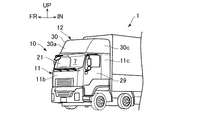
図1に示すように、本実施形態に係るキャブの後面部構造は、キャブ10のルーフパネル30を上方へ膨出させてキャブ10の内部スペース(車室7)を上方へ拡大したハイルーフ型のトラック(車両)1のキャブ10に適用される。
As shown in FIG. 1, the rear surface structure of the cab according to the present embodiment is a high roof type in which the
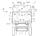
図2に示すように、トラック1は、車両の前後に亘って延びる左右1対のサイドメンバ2と、車幅方向に延びて左右のサイドメンバ2同士を連結する複数のクロスメンバ3とを有する。左右のサイドメンバ2と複数のクロスメンバ3とは、トラック1の車体フレーム4を構成する。キャブ10の前端下部は、フロントキャブマウント(図示省略)を介して車体フレーム4の前端部に回転自在に支持される。キャブ10の後端下部は、左右のサイドメンバ2に対して固定されたリアキャブマウント5を介して車体フレーム4に下方から支持される。なお、図2には、1つのクロスメンバ3のみが示されている。
As shown in FIG. 2, the truck 1 has a pair of left and
キャブ10は、キャブ本体11と、キャブ本体11の上方に配置されてキャブ10の内部スペースを上方へ拡大させるハイルーフ部12とを備え、トラック1の車体フレーム4の前部の上方に配置される。
The
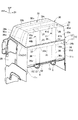
図3及び図4に示すように、キャブ本体11は、ハイルーフ型の車両のキャブ10からハイルーフ部12を除いたものであって、キャブ本体底面部11aと、キャブ本体前面部11b(図1参照)と、左右1対のキャブ本体側面部11cと、キャブ本体後面部11dとを有する。
As shown in FIGS. 3 and 4, the cab
キャブ本体底面部11aは、車室7の下方で上下方向と交叉するフロアパネル13と、フロアパネル13の下方で前後方向に延びる左右1対のキャブアンダーフレーム16とを有し、キャブ10の下方を区画する。フロアパネル13は、リアキャブマウントレール(リアマウントレール)15を有する。リアキャブマウントレール15は、フロアパネル13を上方へ突出するように曲折して形成され、キャブ本体11の後端下部であるフロアパネル13の後端縁部で車幅方向に延び、フロアパネル13の後端縁部の剛性を確保する。リアキャブマウントレール15は、左右1対のマウントブラケット固定部(被支持部)18を有する。左右のマウントブラケット固定部18には、リアキャブマウントブラケット6が固定される。リアキャブマウントブラケット6は、リアキャブマウント5をロック可能なロック装置(図示省略)を有し、リアキャブマウント5に下方から支持される。すなわち、左右のマウントブラケット固定部18は、車体フレーム4に下方から支持される。左右のキャブアンダーフレーム16は、リアキャブマウントレール15の左右のマウントブラケット固定部18から連続して前方へ延び、フロアパネル13の下面に接合される。
The cab main body
キャブ本体前面部11bは、フロントウィンドウ21(図1参照)とフロントウィンドウ21の左右で起立する左右1対のピラー23とを有し、キャブ本体底面部11aの前端縁部に沿って起立して、キャブ10の前方を区画する。フロントウィンドウ21の上方で車幅方向に延びるキャブ本体前面部11bの上端縁部の後面側には、ルーフフロントレール24が固定されて車幅方向に延びる。ルーフフロントレール24は、左右のピラー23の上端部同士を連結し、キャブ本体前面部11bの上端縁部を補強する。キャブ本体前面部11bの上端縁部には、後述するようにハイルーフ部12の前端縁部が固定される。
The cab main body
左右のキャブ本体側面部11cは、車室7を側方に開放するドア開口27と、ドア開口27を開閉自在に閉止する左右のドア29(図3には、左側のドア29のみが示されている)とをそれぞれ有し、キャブ本体底面部11aの車幅方向の両端縁部に沿って起立して、キャブ10の側方(車幅方向両側方)を区画する。左右のキャブ本体側面部11cは、その車幅方向内側に複数のインナーパネル37を有し、複数のインナーパネル37によって補強されている。複数のインナーパネル37は、左右のキャブ本体側面部11cの後端縁部でリアキャブマウントレール15の左右の両端部から連続して上方へ延びるインナーパネル37aと、左右のキャブ本体側面部11cの上端縁部で前後方向に延びるルーフサイドレール37bとを有する。ルーフサイドレール37bは、ルーフフロントレール24の両端部から連続して後方へ延び、左右のキャブ本体側面部11cの上端縁部に固定的に設けられて閉断面を形成し、左右のキャブ本体側面部11cの上端縁部を補強する。ルーフサイドレール37bの後端部は、インナーパネル37aの上端部に連結される。左右のキャブ本体側面部11cの上端縁部には、後述するようにハイルーフ部12の左右の両端縁部が固定される。なお、左右のキャブ本体側面部11cを補強する複数のインナーパネル37は、上記に限定されるものではない。
The left and right cab main
キャブ本体後面部11dは、キャブバックパネル(本体側バックパネル)34と、ルーフバックレール35と、左右1対のバックパネルレインフォース(本体側レインフォース)36とを有する。キャブバックパネル34は、キャブ本体11の後方を区画する板体であって、リアキャブマウントレール15に沿ってキャブ本体11の後端で起立する。キャブバックパネル34の下端縁部は、リアキャブマウントレール15に固定される。ルーフバックレール35は、キャブバックパネル34の上端縁部34aの前面に固定されて車幅方向に延びキャブバックパネル34の上端縁部34aを補強する。ルーフバックレール35の左右の両端部は、左右のキャブ本体側面部11cのルーフサイドレール37bの後端部、及びインナーパネル37aの上端部に連結される。左右のバックパネルレインフォース36は、トラック1の左右両側に配置されてキャブバックパネル34の前面に固定され、鉛直方向に沿って上下方向に直線状に延びる。左右のバックパネルレインフォース36の下端部(本体側下端部)36aは、リアキャブマウントレール15の左右のマウントブラケット固定部18に固定される。左右のバックパネルレインフォース36の上端部(本体側上端部)36bは、ルーフバックレール35の車幅方向の左右の所定の位置32,33に連結される。すなわち、左右のバックパネルレインフォース36の上端部36bは、キャブバックパネル34の上端縁部34aに配置される。なお、ルーフバックレール35の車幅方向の上記所定の位置32,33とは、リアキャブマウントレール15の左右のマウントブラケット固定部18から鉛直方向に沿って上方に直線状に延びる左右のバックパネルレインフォース36が、ルーフバックレール35と交叉する位置である。
The
図3及び図4に示すように、ハイルーフ部12は、キャブ10の内部スペースを上方へ拡大させるように上方へ膨出する樹脂性のルーフパネル30と、ルーフパネル30を補強する複数(本実施形態では、4本)のルーフレインフォース38,39,40,41とによって形成される。ハイルーフ部12は、キャブ本体11を上方から覆うようにキャブ本体11の上方に配置され、キャブ本体11に対して固定される。
As shown in FIGS. 3 and 4, the
複数のルーフレインフォース38〜41は、略逆U字状の前後のルーフレインフォース38,39と、略逆L字状の左右のルーフレインフォース40,41とであり、それぞれが断面ハット状に形成される。前側のルーフレインフォース38は、左右のキャブ本体側面部11cのルーフサイドレール37bに固定されて鉛直方向に沿って直線状に上方へ延びる左右1対の側面補強部38a,38bと、車幅方向に延びて左右の側面補強部38a,38bの上端同士を連結する上面補強部38cとを一体的に有する。後側のルーフレインフォース39は、左右のキャブ本体側面部11cのルーフサイドレール37bに固定されて鉛直方向に沿って直線状に上方へ延びる左右1対の側面補強部39a,39bと、車幅方向に延びて左右の側面補強部39a,39bの上端同士を連結する上面補強部39cとを一体的に有し、前側のルーフレインフォース38から後方に離間した位置に配置される。左右のルーフレインフォース40,41は、後側のルーフレインフォース39の上面補強部39cに固定されて上面補強部39cから後方へ直線状に延びる上面補強部40a,41aと、上面補強部40a,41aの後端から曲折して鉛直方向に沿って直線状に下方へ延びる後面補強部(ルーフ側レインフォース)40b,41bとを一体的に有し、トラック1の左右両側に配置される。左右のルーフレインフォース40,41の後面補強部40b,41bの下端部(ルーフ側下端部)25は、左右のバックパネルレインフォース36の上端部36bの上方に配置されてキャブ本体後面部11dのルーフバックレール35の車幅方向の上記所定の位置32,33に固定され、ルーフバックレール35を介して左右のバックパネルレインフォース36の上端部36bに連続する。すなわち、左右のルーフレインフォース40,41の後面補強部40b,41bと、左右のバックパネルレインフォース36とは、鉛直方向に沿って一直線状に延びる。
The plurality of
ルーフパネル30は、パネル前面部30a(図1参照)とパネル上面部30bと左右のパネル側面部30c,30dとパネル後面部(ルーフ側バックパネル)30eとを一体的に有し、下方へ開放される空間31(図2参照)を区画する。パネル前面部30aは、その下端縁部がキャブ本体前面部11bのルーフフロントレール24に固定され、キャブ本体前面部11bの上端縁部から連続して後上方へ傾斜して延び、ハイルーフ部12の前方を区画する。パネル上面部30bは、パネル前面部30aの上端縁から曲折して後方へ延び、前後のルーフレインフォース38,39の上面補強部38c,39c及び左右のルーフレインフォース40,41の上面補強部40a,41aに上方から接した状態で固定され、ハイルーフ部12の上方を区画する。左右のパネル側面部30c,30dは、パネル上面部30bの車幅方向両端縁から曲折して下方へ延び、前後のルーフレインフォース38,39の側面補強部38a,38b,39a,39bに車幅方向外側から接した状態で固定され、ハイルーフ部12の車幅方向両端で起立してハイルーフ部12の車幅方向両側を区画する。左右のパネル側面部30c,30dの下端縁部は、左右のキャブ本体側面部11cの上端縁部のルーフサイドレール37bに固定される。パネル後面部30eは、パネル上面部30bの後端縁から曲折して下方へ延び、左右のルーフレインフォース40,41の後面補強部40b,41bに後方から接した状態で固定され、ハイルーフ部12の後端で起立してハイルーフ部12の後方を区画する。すなわち、左右のルーフレインフォース40,41の後面補強部40b,41bの上端部(ルーフ側上端部)26は、パネル後面部30eの上端縁部42に配置される。パネル後面部30eの下端縁部は、キャブ本体後面部11dの上端縁部のルーフバックレール35に固定される。
The
上記のように構成されたキャブ10では、左右のルーフレインフォース40,41の後面補強部40b,41bの下端部25は、ルーフバックレール35を介して左右のバックパネルレインフォース36の上端部36bに連続する。すなわち、左右のルーフレインフォース40,41の後面補強部40b,41bと、左右のバックパネルレインフォース36とが、ルーフパネル30のパネル後面部30eの上端縁部とリアキャブマウントレール15との間で上下方向に連続して延びているので、キャブ10の上方または下方からキャブ10の後面部(ルーフパネル30のパネル後面部30e、左右のルーフレインフォース40,41の後面補強部40b,41b、及びキャブ本体後面部11dを含む)に対して下方又は上方への荷重が入力した際(以下、単に荷重の入力時という)に、ハイルーフ部12側とキャブ本体11側との間で効率よく荷重を伝達することができる。このため、左右のバックパネルレインフォース36の上端部36bと、左右のルーフレインフォース40,41の後面補強部40b,41bの下端部25とが車幅方向に異なる位置に配置されて前記両レインフォース36,40b,41bが上下方向に連続しない場合に比べ、荷重の入力時のキャブ10の後面部の所定箇所(例えば、ハイルーフ部12とキャブ本体11との接続部分など)への応力集中を防止することができ、キャブ10の後面部の強度を確保することができる。
In the
また、左右のルーフレインフォース40,41の後面補強部40b,41bと、左右のバックパネルレインフォース36とが鉛直方向に沿って一直線状に延びるので、荷重の入力時にハイルーフ部12側とキャブ本体11側との間で、さらに効率よく荷重を伝達することができ、キャブ10の後面部の強度を確保することができる。
In addition, the
また、左右のバックパネルレインフォース36の下端部36aが、リアキャブマウントレール15の左右のマウントブラケット固定部18に固定され、左右のマウントブラケット固定部18が、車体フレーム4に下方から支持されるので、荷重の入力時にキャブ10の後面部から車体フレーム4側へ荷重を効率よく伝達することができる。
Further, the
また、左右のルーフレインフォース40,41の後面補強部40b,41bと、左右のバックパネルレインフォース36との連結部分に、車幅方向に延びるルーフバックレール35が設けられるので、荷重の入力時にハイルーフ部12からキャブ本体11へ伝達される荷重をルーフバックレール35によって車幅方向両側へ分散することができる。このため、荷重の入力時にハイルーフ部12側からの荷重を左右のキャブ本体側面部11cのインナーパネル37a側へ分散することができ、キャブ10の後面部の所定箇所への応力集中を防止して、キャブ10の後面部の強度を確保することができる。
Further, since the roof back
従って、本実施形態によれば、上方または下方からの荷重に対するハイルーフ型のトラック1のキャブ10の後面部の強度を確保することができる。
Therefore, according to the present embodiment, it is possible to ensure the strength of the rear surface portion of the
なお、本実施形態では、フロアパネル13を上方へ突出するように曲折して形成したリアキャブマウントレール15を設けたが、これに限定されるものではない。例えば、リアキャブマウントレール15を、フロアパネル13とは別体で形成し、該リアキャブマウントレール15に対し、フロアパネル13の後端縁部及びキャブバックパネル34の下端縁部を固定してもよい。
In the present embodiment, the rear
また、本実施形態では、本発明に係るキャブの後面部構造を、前端下部がフロントキャブマウント(図示省略)を介して車体フレーム4の前端部に回転自在に支持される(チルト可能な)キャブ10に適用したが、これに限定されるものではなく、チルトしないキャブ10に適用してもよい。この場合、リアキャブマウントレール15が左右のマウントブラケット固定部18を有することなく、リアキャブマウントレール15の所定の箇所(被支持部)がリアキャブマウント5に直接的または間接的に下方から支持されてもよい。
In the present embodiment, the rear surface structure of the cab according to the present invention is a cab whose front end lower portion is rotatably supported (tiltable) by the front end portion of the vehicle body frame 4 via a front cab mount (not shown). However, the present invention is not limited to this, and may be applied to the
また、本実施形態では、ルーフパネル30のパネル後面部30eを、2つのルーフレインフォース(左右のルーフレインフォース40,41の後面補強部40b,41b)によって補強したが、これに限定されるものではなく、ルーフパネル30のパネル後面部30eを3以上のルーフレインフォースによって補強してもよい。例えば、左右のルーフレインフォース40,41の後面補強部40b,41bに加え、ルーフバックレール35の車幅方向両端部とルーフパネル30のパネル後面部30eの上端縁部との間で上下方向に延びるルーフレインフォース等を設けてもよい。
Further, in this embodiment, the panel
また、本実施形態では、キャブバックパネル34を補強するためにルーフバックレール35と、左右のバックパネルレインフォース36とを設けたが、これに限定されるものではなく、少なくともリアキャブマウントレール15の左右のマウントブラケット固定部18に固定される下端部(本体側下端部)と、キャブバックパネル34の上端縁部34aに配置される上端部(本体側上端部)とを有するバックパネルレインフォース(本体側レインフォース)を設けていればよい。
In the present embodiment, the roof back
また、本実施形態では、左右のルーフレインフォース40,41を設け、左右のルーフレインフォース40,41の後面補強部40b,41bによってルーフパネル30のパネル後面部30eを補強したが、これに限定されるものではなく、少なくともパネル後面部30eの上端縁部42に配置される上端部(ルーフ側上端部)と、左右のバックパネルレインフォース36の上端部36bに連続する下端部(ルーフ側下端部)とを有するルーフレインフォース(ルーフ側レインフォース)を設けていればよい。
Further, in the present embodiment, the left and
また、本実施形態では、左右のルーフレインフォース40,41の後面補強部40b,41bと左右のバックパネルレインフォース36とを、鉛直方向に沿って一直線状に延びるように配置したが、これに限定されるものではない。例えば、左右のルーフレインフォース40,41の後面補強部40b,41bと左右のバックパネルレインフォース36とを、鉛直方向に対して傾斜した状態で一直線状に延びるように配置してもよいし、或いは、左右のルーフレインフォース40,41の後面補強部40b,41b及び左右のバックパネルレインフォース36のうちの一方を鉛直方向に沿って直線状に延びるように配置するとともに、他方を鉛直方向に対して傾斜した状態で直線状に延びるように配置してもよい。
In this embodiment, the left and
以上、本発明について、上記実施形態に基づいて説明を行ったが、本発明は上記実施形態の内容に限定されるものではなく、当然に本発明を逸脱しない範囲で適宜変更が可能である。すなわち、この実施形態に基づいて当業者等によりなされる他の実施形態、実施例および運用技術等は全て本発明の範疇に含まれることは勿論である。 As mentioned above, although this invention was demonstrated based on the said embodiment, this invention is not limited to the content of the said embodiment, Of course, it can change suitably in the range which does not deviate from this invention. That is, it is needless to say that other embodiments, examples, operation techniques, and the like made by those skilled in the art based on this embodiment are all included in the scope of the present invention.
例えば、上記実施形態では、本発明に係るキャブの後面部構造を、ハイルーフ型のトラック1のキャブ10に適用したが、これに限定されるものではなく、トレーラを牽引するハイルーフ型のトラクタ等のキャブに適用してもよい。
For example, in the above-described embodiment, the rear surface structure of the cab according to the present invention is applied to the
1:トラック(車両)
4:車体フレーム
10:キャブ
11:キャブ本体
12:ハイルーフ部
15:リアキャブマウントレール(リアマウントレール)
18:左右1対のマウントブラケット固定部(被支持部)
25:左右のルーフレインフォースの後面補強部の下端部(ルーフ側下端部)
26:左右のルーフレインフォースの後面補強部の上端部(ルーフ側上端部)
30:ルーフパネル
30e:ルーフパネルのパネル後面部(ルーフ側バックパネル)
32,33:ルーフバックレールの車幅方向の所定の位置
34:キャブバックパネル(本体側バックパネル)
34a:キャブバックパネルの上端縁部
35:ルーフバックレール
36:バックパネルレインフォース(本体側レインフォース)
36a:バックパネルレインフォースの下端部(本体側下端部)
36b:バックパネルレインフォースの上端部(本体側上端部)
40,41:左右のルーフレインフォース
40b,41b:左右のルーフレインフォースの後面補強部(ルーフ側レインフォース)
42:ルーフパネルのパネル後面部の上端縁部
1: Truck (vehicle)
4: Body frame 10: Cab 11: Cab body 12: High roof portion 15: Rear cab mount rail (rear mount rail)
18: A pair of left and right mounting bracket fixing parts (supported parts)
25: Lower end of the rear reinforcing part of the left and right roof reinforcement (lower end on the roof side)
26: Upper end of rear reinforcement part of left and right roof reinforcement (upper end of roof side)
30:
32, 33: A predetermined position in the vehicle width direction of the roof back rail 34: Cab back panel (main body side back panel)
34a: Upper edge 35 of the cab back panel 35: Roof back rail 36: Back panel reinforcement (main body side reinforcement)
36a: Lower end of back panel reinforcement (lower end on main body side)
36b: Upper end of back panel reinforcement (upper end on main body side)
40, 41: Left and
42: Upper edge of the rear panel of the roof panel
Claims (3)
前記車体フレームに下方から支持される被支持部を有し、前記キャブ本体の後端下部で車幅方向に延びるリアマウントレールと、
前記リアマウントレールに沿って前記キャブ本体の後端で起立して前記キャブ本体の後方を区画する本体側バックパネルと、
前記リアマウントレールの前記被支持部に固定される本体側下端部と、前記本体側バックパネルの上端縁部に配置される本体側上端部とを有し、前記本体側下端部と前記本体側上端部との間で前記本体側バックパネルに沿って連続して直線状に延び、前記本体側バックパネルに固定されて前記本体側バックパネルを補強する本体側レインフォースと、
前記本体側バックパネルの前記上端縁部から連続して上方へ延びて前記ハイルーフ部の後端で起立し、前記ハイルーフ部の後方を区画するルーフ側バックパネルと、
前記本体側レインフォースの前記本体側上端部の上方に配置されて前記本体側上端部に連続するルーフ側下端部と、前記ルーフ側バックパネルの上端縁部に配置されるルーフ側上端部とを有し、前記ルーフ側下端部と前記ルーフ側上端部との間で前記ルーフ側バックパネルに沿って連続して直線状に延び、前記ルーフ側バックパネルに固定されて前記ルーフ側バックパネルを補強するルーフ側レインフォースと、を備えた
ことを特徴とするキャブの後面部構造。 A cab rear surface structure of a high roof type vehicle in which a cab body is disposed above a body frame, and a high roof portion is fixedly provided above the cab body,
A rear mount rail having a supported portion supported from below by the vehicle body frame and extending in a vehicle width direction at a lower rear end of the cab body;
A body-side back panel that stands up at the rear end of the cab body along the rear mount rail and divides the rear of the cab body;
A main body side lower end portion fixed to the supported portion of the rear mount rail; and a main body side upper end portion disposed at an upper end edge of the main body side back panel, the main body side lower end portion and the main body side. A body-side reinforcement that extends linearly along the body-side back panel between the upper end portion and is fixed to the body-side back panel to reinforce the body-side back panel;
A roof side back panel that continuously extends upward from the upper edge of the main body side back panel and stands at the rear end of the high roof portion, and defines a rear side of the high roof portion;
A roof-side lower end portion disposed above the body-side upper end portion of the body-side reinforcement and continuing to the body-side upper end portion; and a roof-side upper end portion disposed at an upper end edge portion of the roof-side back panel. And extending linearly continuously along the roof side back panel between the roof side lower end portion and the roof side upper end portion, and fixed to the roof side back panel to reinforce the roof side back panel The rear surface structure of the cab is characterized by comprising a roof-side reinforcement.
前記本体側レインフォースと前記ルーフ側レインフォースとは、鉛直方向に沿って一直線状に延びる
ことを特徴とするキャブの後面部構造。 The cab rear surface structure according to claim 1,
The rear surface portion structure of the cab, wherein the main body side reinforcement and the roof side reinforcement extend in a straight line along a vertical direction.
前記本体側バックパネルの前記上端縁部で車幅方向に延び、前記本体側バックパネルに固定されて前記本体側バックパネルの前記上端縁部を補強するルーフバックレールを備え、
前記本体側レインフォースの前記本体側上端部は、前記ルーフバックレールの車幅方向の所定の位置に固定され、
前記ルーフ側レインフォースの前記ルーフ側下端部は、前記ルーフバックレールの車幅方向の前記所定の位置に固定されることによって、前記ルーフバックレールを介して前記本体側上端部に連続する
ことを特徴とするキャブの後面部構造。 The cab rear surface structure according to claim 1 or 2,
A roof back rail that extends in the vehicle width direction at the upper end edge of the main body side back panel, is fixed to the main body side back panel, and reinforces the upper end edge of the main body side back panel;
The main body side upper end of the main body side reinforcement is fixed at a predetermined position in the vehicle width direction of the roof back rail,
The roof side lower end portion of the roof side reinforcement is fixed to the predetermined position in the vehicle width direction of the roof back rail so as to be continuous with the main body side upper end portion via the roof back rail. The rear structure of the cab is a characteristic.
Priority Applications (1)
| Application Number | Priority Date | Filing Date | Title |
|---|---|---|---|
| JP2016028190A JP6674656B2 (en) | 2016-02-17 | 2016-02-17 | Cab structure |
Applications Claiming Priority (1)
| Application Number | Priority Date | Filing Date | Title |
|---|---|---|---|
| JP2016028190A JP6674656B2 (en) | 2016-02-17 | 2016-02-17 | Cab structure |
Publications (2)
| Publication Number | Publication Date |
|---|---|
| JP2017144884A true JP2017144884A (en) | 2017-08-24 |
| JP6674656B2 JP6674656B2 (en) | 2020-04-01 |
Family
ID=59681948
Family Applications (1)
| Application Number | Title | Priority Date | Filing Date |
|---|---|---|---|
| JP2016028190A Active JP6674656B2 (en) | 2016-02-17 | 2016-02-17 | Cab structure |
Country Status (1)
| Country | Link |
|---|---|
| JP (1) | JP6674656B2 (en) |
Cited By (4)
| Publication number | Priority date | Publication date | Assignee | Title |
|---|---|---|---|---|
| JP2019194049A (en) * | 2018-05-02 | 2019-11-07 | いすゞ自動車株式会社 | Roof panel and cab structure |
| JP2020152170A (en) * | 2019-03-18 | 2020-09-24 | いすゞ自動車株式会社 | Vehicle roof panel reinforcement structure |
| WO2024127734A1 (en) | 2022-12-16 | 2024-06-20 | ダイムラー トラック エージー | Truck high roof structure |
| JP7525034B1 (en) | 2023-11-22 | 2024-07-30 | いすゞ自動車株式会社 | vehicle |
Citations (2)
| Publication number | Priority date | Publication date | Assignee | Title |
|---|---|---|---|---|
| JP2005255095A (en) * | 2004-03-15 | 2005-09-22 | Mitsubishi Fuso Truck & Bus Corp | Cab structure of cab-over-engine truck |
| JP2014054943A (en) * | 2012-09-13 | 2014-03-27 | Daimler Ag | Shock absorbing structure of vehicle |
-
2016
- 2016-02-17 JP JP2016028190A patent/JP6674656B2/en active Active
Patent Citations (2)
| Publication number | Priority date | Publication date | Assignee | Title |
|---|---|---|---|---|
| JP2005255095A (en) * | 2004-03-15 | 2005-09-22 | Mitsubishi Fuso Truck & Bus Corp | Cab structure of cab-over-engine truck |
| JP2014054943A (en) * | 2012-09-13 | 2014-03-27 | Daimler Ag | Shock absorbing structure of vehicle |
Cited By (7)
| Publication number | Priority date | Publication date | Assignee | Title |
|---|---|---|---|---|
| JP2019194049A (en) * | 2018-05-02 | 2019-11-07 | いすゞ自動車株式会社 | Roof panel and cab structure |
| JP7141594B2 (en) | 2018-05-02 | 2022-09-26 | いすゞ自動車株式会社 | Cab structure |
| JP2020152170A (en) * | 2019-03-18 | 2020-09-24 | いすゞ自動車株式会社 | Vehicle roof panel reinforcement structure |
| JP7194358B2 (en) | 2019-03-18 | 2022-12-22 | いすゞ自動車株式会社 | Vehicle roof panel reinforcement structure |
| WO2024127734A1 (en) | 2022-12-16 | 2024-06-20 | ダイムラー トラック エージー | Truck high roof structure |
| EP4620791A1 (en) | 2022-12-16 | 2025-09-24 | Daimler Truck AG | Truck high roof structure |
| JP7525034B1 (en) | 2023-11-22 | 2024-07-30 | いすゞ自動車株式会社 | vehicle |
Also Published As
| Publication number | Publication date |
|---|---|
| JP6674656B2 (en) | 2020-04-01 |
Similar Documents
| Publication | Publication Date | Title |
|---|---|---|
| US8979173B2 (en) | Vehicle body floor structure for automobile | |
| JP5352682B2 (en) | Body floor structure | |
| JP6103142B2 (en) | Rear body structure of automobile | |
| CN102632927B (en) | Rear structure of vehicle body | |
| JP5593813B2 (en) | Body reinforcement structure | |
| EP2740651A1 (en) | Vehicle body lateral structure | |
| JP7259506B2 (en) | vehicle rear body structure | |
| EP3566931B1 (en) | Vehicle body structure, and vehicle | |
| CN104058009B (en) | Vehicle Body Rear Structure | |
| JP4904245B2 (en) | Body structure | |
| JP3866176B2 (en) | Body structure | |
| JP2013144525A (en) | Vehicle body front structure of vehicle | |
| CN107097858A (en) | Body structure | |
| JP4438416B2 (en) | Front body structure of the vehicle | |
| JP2016196203A (en) | Vehicular rear part structure | |
| JP6674656B2 (en) | Cab structure | |
| JP4822191B2 (en) | Body front structure | |
| JP6156088B2 (en) | Front body structure of the vehicle | |
| JP2012035739A (en) | Automotive vehicle body side part structure | |
| JP2011173506A (en) | Cross member structure | |
| JP2009040127A (en) | Front body structure of automobile | |
| JP4696664B2 (en) | Rear body structure of the vehicle | |
| JP2017128299A (en) | Vehicle body structure | |
| JP2019116123A (en) | Vehicle body front section structure | |
| JP2017218119A (en) | Rear structure of cab |
Legal Events
| Date | Code | Title | Description |
|---|---|---|---|
| A621 | Written request for application examination |
Free format text: JAPANESE INTERMEDIATE CODE: A621 Effective date: 20190129 |
|
| A977 | Report on retrieval |
Free format text: JAPANESE INTERMEDIATE CODE: A971007 Effective date: 20191114 |
|
| A131 | Notification of reasons for refusal |
Free format text: JAPANESE INTERMEDIATE CODE: A131 Effective date: 20191122 |
|
| A521 | Request for written amendment filed |
Free format text: JAPANESE INTERMEDIATE CODE: A523 Effective date: 20200121 |
|
| TRDD | Decision of grant or rejection written | ||
| A01 | Written decision to grant a patent or to grant a registration (utility model) |
Free format text: JAPANESE INTERMEDIATE CODE: A01 Effective date: 20200207 |
|
| A61 | First payment of annual fees (during grant procedure) |
Free format text: JAPANESE INTERMEDIATE CODE: A61 Effective date: 20200220 |
|
| R150 | Certificate of patent or registration of utility model |
Ref document number: 6674656 Country of ref document: JP Free format text: JAPANESE INTERMEDIATE CODE: R150 |