JP2017144932A - Refrigeration device for vehicle - Google Patents
Refrigeration device for vehicle Download PDFInfo
- Publication number
- JP2017144932A JP2017144932A JP2016029514A JP2016029514A JP2017144932A JP 2017144932 A JP2017144932 A JP 2017144932A JP 2016029514 A JP2016029514 A JP 2016029514A JP 2016029514 A JP2016029514 A JP 2016029514A JP 2017144932 A JP2017144932 A JP 2017144932A
- Authority
- JP
- Japan
- Prior art keywords
- unit
- vehicle
- cargo compartment
- refrigeration
- evaporator
- Prior art date
- Legal status (The legal status is an assumption and is not a legal conclusion. Google has not performed a legal analysis and makes no representation as to the accuracy of the status listed.)
- Pending
Links
Images


Landscapes
- Air-Conditioning For Vehicles (AREA)
Abstract
Description
本発明は、車両用冷凍装置に関し、特に、車両の荷台に搭載される冷凍コンテナ等の荷室内を区画して、各々異なる温度で管理するのに有効な一体型の車両用冷凍装置に関する。 The present invention relates to a vehicular refrigeration apparatus, and more particularly, to an integrated vehicular refrigeration apparatus that is effective for partitioning a cargo compartment such as a refrigeration container mounted on a vehicle loading platform and managing the compartments at different temperatures.
従来からこの種の車両用冷凍装置を備えた軽トラックや小型トラックなどの小型貨物自動車や中型貨物自動車、大型貨物自動車等による冷凍車では、一般的に車両のエンジンルームに圧縮機(コンプレッサ)が設けられ、凝縮機(コンデンサ)ユニットを冷凍コンテナの外壁等に取り付け、蒸発器(エバポレータ)ユニットを冷凍コンテナ内に設置するという状態で、それぞれ別体で配置されている。そのため、構造が複雑となり、冷媒配管の取り回しも煩雑となっている。また、エンジンルーム内の圧縮機は、エンジンが停止すれば作動を停止するため、冷凍車の利用には大きな制約があった。 Conventionally, in small trucks such as light trucks and small trucks equipped with this type of refrigeration system for vehicles, medium trucks, and refrigeration trucks such as large trucks, a compressor (compressor) is generally installed in the engine room of the vehicle. The condenser (condenser) unit is provided on the outer wall of the refrigeration container and the evaporator (evaporator) unit is installed in the refrigeration container. Therefore, the structure is complicated, and the handling of the refrigerant piping is also complicated. In addition, since the compressor in the engine room stops operating when the engine stops, there are significant restrictions on the use of the refrigerator car.
また、近年では、冷凍車において搬送物の多様化が進んでおり、これに伴い、冷凍コンテナ内を複数の室に区画して、それぞれ搬送物に適した異なる温度で管理されることが望まれている。このため、例えば特許文献1に記載された車両用冷凍装置の普及が期待されている。
Further, in recent years, the diversification of conveyed items has progressed in refrigerated vehicles, and accordingly, it is desirable to divide the inside of a refrigerated container into a plurality of chambers and to manage them at different temperatures suitable for the conveyed items. ing. For this reason, for example, the spread of the vehicle refrigeration apparatus described in
ここで、冷凍車とは、車両の荷台等に冷凍コンテナ等の冷凍庫・冷蔵庫として機能する荷室が設けられ、搬送する荷物(以下、搬送物と称す)を、それに適した温度で管理しながら搬送することが可能な車両を意味する。なお、以下では冷凍・冷蔵のような冷却機能に関し例示するが、冷凍サイクルを逆回転させることによる加温機能も含むものとする。 Here, a freezer truck is provided with a cargo compartment functioning as a freezer / refrigerator such as a freezer container in a vehicle loading platform, etc., and managing a cargo to be transported (hereinafter referred to as a transported item) at a temperature suitable for it. It means a vehicle that can be transported. In addition, although illustrated about the cooling function like freezing and refrigeration below, the heating function by reverse-rotating a refrigerating cycle shall also be included.
かかる特許文献1の車両用冷凍装置では、冷凍コンテナ内を複数の室に区画する各コールドボックスに、それぞれ制御系統(情報コンセント)や電源コンセント、冷凍機などが設けられており、充電式のバッテリを電源として用いている。そのため、構造が簡略化され、面倒な配線の架設作業が省けるので容易に設置できる上、従来のような車両のエンジンを利用して駆動する必要がない(換言すれば、車両用冷凍装置の作動をエンジンに依存する必要がない)。しかしながら、各コールドボックスにおいて、冷凍機などの設置スペース分、搬送物の積載スペースが狭くなり、積載可能な搬送物が減らされると共に、各コールドボックスにそれぞれ冷凍機などの設備が設けられる分、架装費用・架装時間・ランニングコストが嵩む問題があった。
In such a vehicle refrigeration apparatus disclosed in
本発明は、上述のような課題に鑑みなされたものであって、冷凍車における冷凍庫内が複数の室に区画された場合であっても、搬送物の積載スペースを狭めることなく、それぞれ所望の温度で管理できると共に、取付作業に要する構成部品、時間、労力およびランニングコストを大幅に削減可能な車両用冷凍装置を提供することを目的とする。 The present invention has been made in view of the above-described problems, and even when the inside of a freezer in a freezer car is partitioned into a plurality of chambers, each desired object can be obtained without narrowing the loading space for the conveyed items. An object of the present invention is to provide a vehicle refrigeration apparatus that can be controlled by temperature and that can significantly reduce the components, time, labor, and running cost required for installation work.
上述のような課題を解決するために、本発明に係る車両用冷凍装置は、
車両の荷台に搭載された荷室内を温度管理するための車両用冷凍装置であって、
前記荷室内が複数の室に区画され、
冷媒を圧縮する電動圧縮機を有し、前記各室に対応してそれぞれ設けられる複数のコンプレッサユニットと、
前記コンプレッサユニットにて圧縮された前記冷媒から熱を放出させる凝縮機を有し、前記各室に対応してそれぞれ設けられる複数のコンデンサユニットと、を備える外部ユニットと、
前記コンデンサユニットにて冷却された冷媒を用いて前記荷室内の空気を冷却する蒸発器を有するエバポレータユニットを備え、前記各室に対応してそれぞれ設けられる複数の内部ユニットと、
前記外部ユニットおよび少なくとも1つの前記内部ユニットを一体的に組付けるための本体フレームと、を備え、
前記各室のうち、1つの室には前記本体フレームを介して前記外部ユニットと、少なくとも1つの前記内部ユニットとが取り付けられ、他の室にはそれぞれ前記内部ユニットが取り付けられていることを特徴とする。
In order to solve the above-described problems, a vehicle refrigeration apparatus according to the present invention includes:
A vehicle refrigeration apparatus for controlling the temperature of a cargo compartment mounted on a vehicle bed,
The cargo compartment is partitioned into a plurality of chambers;
A plurality of compressor units each having an electric compressor for compressing a refrigerant and provided for each of the chambers;
An external unit comprising a condenser for releasing heat from the refrigerant compressed by the compressor unit, and a plurality of condenser units respectively provided corresponding to the chambers;
An evaporator unit having an evaporator for cooling the air in the cargo compartment using the refrigerant cooled in the capacitor unit, and a plurality of internal units respectively provided corresponding to the chambers;
A main body frame for integrally assembling the external unit and at least one of the internal units;
Among the chambers, one chamber is provided with the external unit and at least one internal unit via the main body frame, and the other unit is provided with the internal unit. And
これによれば、外部ユニットおよび少なくとも1つの内部ユニットが本体フレームに一体化して組付けられるため、車両用冷凍装置の取り付けに要する構成部品、時間および労力を大幅に削減することができる。しかも、一体化によって冷媒配管等の配設も簡略化でき、装置全体としてコンパクト化を図ることができるので、コンプレッサユニットとエバポレータユニットとコンデンサユニットの取付スペースを削減することができ、冷凍コンテナ内の空間におけるエバポレータユニットの占有面積を削減することができる。また、構成要素(コンプレッサユニット・エバポレータユニット・コンデンサユニット等)毎に機能が完結しているため、冷凍車における冷凍庫内が複数の室に区画された場合であっても、各要素の設計変更、仕様変更等に柔軟に対応でき、設計の自由度を広げることができる上、メンテナンス性にも優れている。かくして、冷凍車における複数の室に区画された冷凍庫内における搬送物の積載スペースを狭めることなく、それぞれ所望の温度で管理できると共に、取付作業に要する構成部品、時間、労力およびランニングコストを大幅に削減できる。 According to this, since the external unit and at least one internal unit are integrated and assembled to the main body frame, it is possible to significantly reduce the components, time and labor required for mounting the vehicle refrigeration apparatus. Moreover, the integration of the refrigerant pipes and the like can be simplified by integration, and the overall apparatus can be made compact, so that the installation space for the compressor unit, the evaporator unit and the condenser unit can be reduced, and the inside of the refrigeration container can be reduced. The area occupied by the evaporator unit in the space can be reduced. In addition, since the function is completed for each component (compressor unit, evaporator unit, condenser unit, etc.), even if the freezer in the freezer car is partitioned into multiple chambers, the design change of each element, It can flexibly respond to specification changes, etc., and can be designed with a wide range of design, and it is also easy to maintain. Thus, it is possible to manage at a desired temperature without narrowing the loading space of the transported goods in the freezer partitioned into a plurality of chambers in the freezer car, and greatly reduce the components, time, labor and running cost required for installation work. Can be reduced.
また、各室の設定温度に対応して、内部ユニット(すなわち、エバポレータユニット)毎に適宜、冷媒を異なる種類で選択または変更できるため、エバポレータユニット毎に対応する電動圧縮機の負担を減らすことができ、冷凍サイクルの効率化を図ることができる。
すなわち、前記外部ユニットに設けられる前記複数のコンプレッサユニットおよび前記複数のコンデンサユニットと、前記複数の内部ユニットにそれぞれ設けられるエバポレータユニットと、における各コンプレッサユニット、コンデンサユニット、エバポレータユニットを有して構築される複数の冷凍サイクルのうち、少なくとも一つの冷凍サイクルは、当該冷凍サイクルに対応する前記室の設定温度に応じて、他の冷凍サイクルとは異なる種類の冷媒が用いられている構成とすることができる。
Further, since the refrigerant can be selected or changed in different types as appropriate for each internal unit (that is, the evaporator unit) corresponding to the set temperature of each chamber, the burden on the electric compressor corresponding to each evaporator unit can be reduced. It is possible to improve the efficiency of the refrigeration cycle.
That is, the compressor unit, the capacitor unit, and the evaporator unit in each of the plurality of compressor units and the plurality of capacitor units provided in the external unit and the evaporator unit provided in each of the plurality of internal units are constructed. Among the plurality of refrigeration cycles, at least one refrigeration cycle may have a configuration in which a different type of refrigerant from the other refrigeration cycles is used according to the set temperature of the chamber corresponding to the refrigeration cycle. it can.
また、本発明の車両用冷凍装置は、
車両の荷台に搭載された荷室内を温度管理するための車両用冷凍装置であって、
前記荷室が複数の室に区画されておらず、
冷媒を圧縮する電動圧縮機を有するコンプレッサユニットと、
前記コンプレッサユニットにて圧縮された前記冷媒から熱を放出させる凝縮機を有するコンデンサユニットと、を備える外部ユニットと、
前記コンデンサユニットにて冷却された冷媒を用いて前記荷室内の空気を冷却する蒸発器を有するエバポレータユニットを備える内部ユニットと、
前記外部ユニットおよび前記内部ユニットを一体的に組付けるための本体フレームと、を備え、
前記外部ユニットにおける前記コンプレッサユニットおよび前記コンデンサユニットと、前記内部ユニットにおける前記エバポレータユニットとは、それぞれ前記荷室内を管理する設定温度に対応した能力に応じた個数だけ設置されることを特徴とする。
In addition, the vehicle refrigeration apparatus of the present invention,
A vehicle refrigeration apparatus for controlling the temperature of a cargo compartment mounted on a vehicle bed,
The cargo room is not partitioned into a plurality of rooms,
A compressor unit having an electric compressor for compressing the refrigerant;
An external unit comprising a condenser unit having a condenser for releasing heat from the refrigerant compressed by the compressor unit;
An internal unit comprising an evaporator unit having an evaporator for cooling the air in the cargo compartment using the refrigerant cooled in the capacitor unit;
A main body frame for assembling the external unit and the internal unit integrally;
The compressor unit and the capacitor unit in the external unit, and the evaporator unit in the internal unit are installed in the number corresponding to the capacity corresponding to the set temperature for managing the cargo compartment.
これによれば、荷室が複数の室に区画されない場合、当該荷室内を管理する設定温度に応じた能力に対応して、外部ユニットにおけるコンプレッサユニットおよびコンデンサユニットの設置数と、内部ユニットにおけるエバポレータユニットの設置数とを、適宜、変更して設けることができる。このため、設定温度に対応する冷却能力に応じて、予め冷凍装置として各種バリエーションを設ける必要がなく、コンプレッサユニット,コンデンサユニット,エバポレータユニットを有して構築される冷凍システムの設置数(設置単位)を変更するだけで対応することができる。よって、車両用冷凍装置として必要な構成部品、取付時間および労力、ランニングコストを大幅に削減できる。 According to this, when the cargo compartment is not divided into a plurality of chambers, the number of compressor units and capacitor units installed in the external unit and the evaporator in the internal unit are accommodated in accordance with the capability according to the set temperature for managing the cargo compartment. The number of units installed can be changed as appropriate. For this reason, it is not necessary to provide various types of refrigeration equipment in advance according to the cooling capacity corresponding to the set temperature, and the number of installed refrigeration systems (installation units) constructed with a compressor unit, a condenser unit, and an evaporator unit. You can respond by changing Therefore, it is possible to greatly reduce the components, installation time and labor, and running cost required for the vehicle refrigeration system.
このとき、前記本体フレームは、
前記外部ユニットを配置する荷室外部側と、前記内部ユニットを配置する荷室内部側とが荷室隔壁部を介在して隣接した状態で一体化されており、
前記荷室隔壁部を中心として、前記荷室外部側と前記荷室内部側とを略均等な重量バランスで配置していることが好ましい。
At this time, the body frame is
The exterior side of the cargo compartment in which the external unit is arranged and the interior side of the cargo compartment in which the internal unit is arranged are integrated in a state adjacent to each other with a cargo compartment partition wall interposed therebetween,
It is preferable that the outside of the cargo compartment and the inside of the cargo compartment are arranged with a substantially equal weight balance around the cargo compartment partition.
これによれば、コンプレッサユニットおよびコンデンサユニットを配置する荷室外部側と、エバポレータユニットを配置する荷室内部側と、が本体フレームにおいて荷室隔壁部を中心に略均等な重量バランスで配置されているため、荷室に取り付けられた状態において、取付開口部を介して荷室の内側と外側とで重量配分を均等にすることができ、当該取付開口部への曲げモーメントを軽減することができる。 According to this, the cargo compartment exterior side where the compressor unit and the capacitor unit are arranged and the cargo compartment side where the evaporator unit is arranged are arranged with a substantially equal weight balance around the cargo compartment partition in the main body frame. Therefore, in the state attached to the luggage compartment, the weight distribution can be made uniform between the inside and outside of the luggage compartment via the attachment opening, and the bending moment to the attachment opening can be reduced. .
また、本発明において、
前記荷室には、前記車両の進行方向前方における上方の位置に前記本体フレームに対応する取付開口部が貫設されており、
前記本体フレームは、前記荷室内部側を前記取付開口部に挿入して嵌め込まれた状態で、且つ、前記荷室隔壁部が前記荷室の前記取付開口部周辺に当接した状態で前記荷室に取り付けられていることが好ましい。
In the present invention,
An attachment opening corresponding to the main body frame is provided through the cargo compartment at an upper position in the forward direction of the vehicle,
The main body frame is inserted in and inserted into the mounting opening on the side of the cargo compartment, and the cargo compartment partition wall is in contact with the periphery of the mounting opening of the cargo compartment. It is preferably attached to the chamber.
これによれば、本体フレームを荷室(冷凍コンテナ)の取付開口部に取り付けるだけで、荷室内部側に配置されたエバポレータユニットを冷凍コンテナの内部に配置した状態で車両用冷凍装置を取り付けることができる。このとき、冷凍コンテナに本体フレームの形状に応じた取付開口部を用意するだけで、各種の車両に適用することができるので、汎用性を高めることができる。また、荷室隔壁部が荷室の取付開口部周辺に当接した状態で取り付けられるため、当該取付開口部の周囲を荷室隔壁部によって覆うことができ、この取付開口部から荷室内の冷気が漏れるのを未然に防止でき、密閉性を確保できる。 According to this, only by attaching the main body frame to the loading opening of the cargo compartment (refrigeration container), the vehicle refrigeration apparatus is attached in a state where the evaporator unit arranged on the cargo compartment inner side is arranged inside the refrigeration container. Can do. At this time, it is possible to improve versatility because it can be applied to various types of vehicles simply by preparing a mounting opening corresponding to the shape of the main body frame in the refrigeration container. Further, since the cargo compartment partition wall is attached in a state of being in contact with the vicinity of the mounting opening of the cargo compartment, the periphery of the mounting opening can be covered by the cargo compartment bulkhead, and the cooling air in the cargo compartment can be covered from the mounting opening. Can be prevented in advance, and sealing can be secured.
さらに、本発明において、
前記車両のエンジンにより駆動され、前記コンプレッサユニット、前記エバポレータユニットおよび前記コンデンサユニット専用の発電機と、
前記発電機により充電されるバッテリと、
少なくとも前記電動圧縮機の動作を制御する制御部と、
前記バッテリを電源として電力を入力し、当該入力した電力を前記制御部による制御に基づき、前記電動圧縮機を駆動するための電力に変換して供給する電力変換装置と、
商用電源から電力を取り込み、交流出力から直流に変換して整流する充電器と、を更に備え、
前記バッテリは、前記発電機または前記充電器により充電されることが好ましい。
Furthermore, in the present invention,
Driven by the engine of the vehicle, a generator dedicated to the compressor unit, the evaporator unit and the capacitor unit;
A battery charged by the generator;
A controller that controls at least the operation of the electric compressor;
A power converter that inputs power using the battery as a power source, converts the input power into power for driving the electric compressor based on control by the control unit, and
A charger that takes in electric power from a commercial power source, converts the AC output into direct current, and rectifies it;
It is preferable that the battery is charged by the generator or the charger.
これによれば、専用の発電機によって充電される専用のバッテリを備えているので、従来のような車両のエンジンを利用して冷凍装置を駆動する必要がない。換言すれば、車両用冷凍装置の作動をエンジンに依存する必要がない。よって、配達等で停車する場合にエンジンを停止しても、車両用冷凍装置は独立して運転の継続が可能なため、冷凍コンテナ内の低温状態を維持できる。すなわち、停車中においても車両のエンジンをアイドリング状態とする必要がないため、消費燃料の増加や排出ガスによる環境汚染を未然に回避できる。しかも、バッテリを充電する手段として商用電源から電力を取り込む充電器を備えることにより、走行中においてはエンジンによって駆動される専用の発電機を用いてバッテリを充電できると共に、停車中においては商用電源を確保できる場合、車両のエンジンを駆動することなく、当該商用電源から電力を取り込む充電器によりバッテリを充電できる。 According to this, since the dedicated battery charged by the dedicated generator is provided, there is no need to drive the refrigeration apparatus using a conventional vehicle engine. In other words, the operation of the vehicle refrigeration apparatus does not need to depend on the engine. Therefore, even if the engine is stopped when the vehicle is stopped for delivery or the like, the vehicle refrigeration apparatus can continue to operate independently, so that the low temperature state in the refrigeration container can be maintained. That is, since it is not necessary to set the vehicle engine to an idling state even when the vehicle is stopped, an increase in fuel consumption and environmental pollution due to exhaust gas can be avoided. Moreover, by providing a charger that takes in electric power from a commercial power source as a means for charging the battery, the battery can be charged using a dedicated generator driven by the engine while traveling, and the commercial power source can be used when the vehicle is stopped. If it can be secured, the battery can be charged by a charger that takes in power from the commercial power supply without driving the engine of the vehicle.
このとき、前記コンデンサユニットは、前記本体フレームに設けられるケーシングによって覆われており、前記ケーシングには、前記進行方向前方から前記外気を取り込むための吸気口が設けられていることが好ましい。また、前記コンデンサユニットは、前記本体フレームに設けられるケーシングによって覆われており、前記ケーシングには、前記熱を上方に向けて放出するための放熱部が設けられていることが好ましい。 At this time, it is preferable that the capacitor unit is covered with a casing provided in the main body frame, and the casing is provided with an intake port for taking in the outside air from the front in the traveling direction. Moreover, it is preferable that the said capacitor | condenser unit is covered with the casing provided in the said main body flame | frame, and the said heat sink part for discharging | emitting the said heat upwards is provided in the said casing.
これによれば、車両前方からの風(外気)を取り込み易く、凝縮器(コンデンサ)の吹き出しをスムーズにさせることができる。よって、放熱性に優れ、凝縮器における熱交換効率の向上を図ることができる。 According to this, it is easy to take in wind (outside air) from the front of the vehicle, and the condenser (condenser) can be smoothly blown out. Therefore, it is excellent in heat dissipation and can improve the heat exchange efficiency in the condenser.
以上、説明したように、本発明によれば、冷凍車における冷凍庫内が複数の室に区画された場合であっても、搬送物の積載スペースを狭めることなく、それぞれ所望の温度で管理できると共に、取付作業に要する構成部品、時間、労力およびランニングコストを大幅に削減できる。 As described above, according to the present invention, even if the inside of the freezer in the freezer car is partitioned into a plurality of chambers, each can be managed at a desired temperature without narrowing the loading space of the conveyed product. The components, time, labor, and running costs required for installation work can be greatly reduced.
以下、図面を参照しながら本発明の一実施形態について説明する。
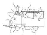
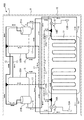
図1および図2には、本発明による車両用冷凍装置の一実施の形態が示されている。本実施形態の車両用冷凍装置1は、例えば、貨物自動車の荷台に搭載される荷室としての冷凍コンテナKにおける複数に区画された各室K1,K2内を、それぞれ任意の温度で冷却(すなわち、冷凍や冷蔵)する冷凍装置に適用され、設置スペースの省スペース化を図ると共に、取付作業に要する構成部品、時間および労力を大幅に削減するのに有効なものである。なお、以下の説明において、車両の進行方向前方とは図1の紙面における左の方向を示し、上方とは図1の紙面における上の方向を示すものとする。
Hereinafter, an embodiment of the present invention will be described with reference to the drawings.
1 and 2 show an embodiment of a vehicle refrigeration apparatus according to the present invention. The
<システムの構成について>
図1および図2に示すように、本実施形態の車両用冷凍装置1は、前述の中型貨物自動車を用いた冷凍車Cの冷凍コンテナKに設けられる区画壁11によって複数に区画された各室K1,K2に取り付けられるものである。このとき、第1室K1には、外部ユニットとしての冷凍機本体7と、内部ユニットとしての第1エバポレータユニット10Aとが本体フレーム9を介して一体的に取り付けられ、第2室には、内部ユニットとしての第2エバポレータユニット10Bが取り付けられている。
<System configuration>
As shown in FIGS. 1 and 2, the
冷凍機本体7は、冷媒を圧縮する電動圧縮機(後述する第1および第2コンプレッサ21A,21B)を有するコンプレッサユニット21と、コンプレッサユニット21にて圧縮された冷媒を外気と熱交換させて熱を放出させるコンデンサ22およびコンデンサファン23を有するコンデンサユニット20と、からなり、これらコンデンサユニット20とコンプレッサユニット21とがそれぞれ各室K1,K2に対応して複数設けられている。具体的に、本実施形態の場合、図2に示すように、冷凍機本体7には、第1室K1用の第1コンプレッサ21Aおよび第1コンデンサ22Aと、第2室K2用の第2コンプレッサ21Bおよび第2コンデンサ22Bとが一体的に設けられている。なお、本発明はこれに限らず、例えば、冷凍コンテナKが3つの室に区画された場合、これらコンデンサユニット20とコンプレッサユニット21とがそれぞれ3つずつ、冷凍機本体7に設けられることとなる。
The refrigerator main body 7 heats the
第1および第2エバポレータユニット10A,10Bは、それぞれ冷媒を用いて冷凍コンテナK内の空気を冷却するものであり、本実施形態の場合、冷凍コンテナKが2つの室K1,K2に区画されているため、各室10A,10Bに対応して複数(ここでは、2つ)設けられている。すなわち、冷凍コンテナKが、例えば3つの室に区画された場合、エバポレータユニットは、各室に対応して3つ設けられることとなる。
Each of the first and
このように、車両用冷凍装置1では、冷凍コンテナKの複数に区画された各室K1,K2を冷却するための冷凍サイクルを構築するコンプレッサユニット21(第1および第2コンプレッサ21A,21B)、コンデンサユニット20(第1および第2コンデンサ22A,22B)、第1および第2エバポレータユニット10A,10Bが、各室K1,K2に対応した系統(この場合、2系統)設けられる。そして、これら2系統は、システム的に完全に独立しているため、各室K1,K2を管理する温度設定に応じて、それぞれの冷凍サイクルに種類の異なる冷媒を選択することが可能となる。例えば、第1室K1をマイナス25℃程度の低温設定とする場合、冷媒としては、より蒸発温度の低く冷凍能力の大きいR404Aを選定する。一方、第2室K2はマイナス10度程度の中温設定とする場合、冷媒としては、蒸発温度が比較的高いR134aを選定する。このように、管理する温度設定に応じて、それぞれ異なる種類の冷媒を選択することにより、コンプレッサ(第1および第2コンプレッサ21A,21B)にとって負荷の大きい、例えばR404Aを必要な荷室のみに限定でき、車両用冷凍装置1全体の負荷の軽減に寄与することが可能となる。
Thus, in the
本体フレーム9は、冷凍機本体7および第1エバポレータユニット10Aを一体的に組付けるためのもので、冷凍機本体7が配置された荷室外部側と、第1エバポレータユニット10Aが配置された荷室内部側との境界部位に、荷室隔壁部40が介在されている。そして、この荷室隔壁部40を境に、荷室外部側と荷室内部側との重量バランスが略均等となるように配置されている。
The main body frame 9 is for assembling the refrigerator main body 7 and the
具体的に、冷凍コンテナKにおける進行方向前方の上方の位置には、本体フレーム9の荷室内部側に配置される第1エバポレータユニット10Aに対応する取付開口部30が貫設されている。そして、本体フレーム9は、この取付開口部30に対して、第1エバポレータユニット10A側を挿入して荷室隔壁部40を嵌め込むことで、当該第1エバポレータユニット10Aを冷凍コンテナKの第1室K1内部に配置した状態で取り付けられる。このとき、本体フレーム9は、当該冷凍コンテナKの外壁面に沿うように当接し、取付開口部30を閉塞するようになっている。
Specifically, a mounting
また、車両用冷凍装置1は、冷凍車Cの図示省略するエンジンにより駆動される冷凍装置用発電機4(オルタネータ)と、商用電源から電力を取り込み、交流出力から直流に変換して整流する充電器8と、冷凍装置用発電機4または充電器8により充電される冷凍装置用バッテリ3(サブバッテリ)と、コンプレッサユニット21に設けられた第1および第2コンプレッサ21A,21Bの動作を制御する不図示の駆動部と、当該駆動部による制御に基づき、冷凍装置用バッテリ3を電源として入力される電力(例えば、12Vや24V)を、第1および第2コンプレッサ21A,21Bを駆動するための電力(例えば、300V)に変換(昇圧)して供給する電力変換装置としてのDC/DCコンバータ2と、を備えている。
The
なお、冷凍車Cには、エンジンにより駆動され、車両の各種補機(オーディオ・エアコン等)にて使用される電力を発電したり、車両用バッテリ5(メインバッテリ)を充電したりする車両用発電機6(オルタネータ)が別途備えられている。
しかしながら、本実施形態の車両用冷凍装置1の場合、冷凍装置用バッテリ3および冷凍装置用発電機4が設けられていると共に、当該冷凍装置用バッテリ3によって駆動される第1および第2コンプレッサ21A,21Bも従来のようなエンジンによって駆動される機械式コンプレッサではないため、エンジンルームに配置されるのではなく、コンプレッサユニット21としてコンデンサユニット20と一緒に本体フレーム9の荷室外部側に配置されている。よって、車両用冷凍装置1の作動に際し、エンジンの駆動・停止に依存することはない。また、コンプレッサユニット21とコンデンサユニット20と第1エバポレータユニット10Aとが一体化され、第2室K2を冷却するための第2エバポレータユニット10Bも機能が完結しているため、冷凍サイクルに係る配管の取り回しも簡略化できる利点を備えている。
The refrigerator C is driven by an engine and generates electric power used by various auxiliary machines (audio / air conditioner, etc.) of the vehicle or charges a vehicle battery 5 (main battery). A generator 6 (alternator) is separately provided.
However, in the case of the
<エバポレータユニットの構成>
第1および第2エバポレータユニット10A,10Bは、冷凍コンテナKの複数(この場合、2つ)に区画された内部空間(第1室および第2室内)を冷却する部分であり、それぞれエバポレータ12A,12B(蒸発器)、エバポレータファン(不図示)、温度センサ13A,13Bおよび第1,第2電子膨張弁14A,14B等を有して構成され、冷凍コンテナKの対応する各室K1,K2内に配設される。
<Evaporator unit configuration>
The first and
各エバポレータ12A,12Bは、それぞれコンデンサユニット20から高温・高圧配管15と第1,第2電子膨張弁14A,14Bとを介して送られてくる冷媒を、冷凍コンテナK内の空気と熱交換させることで、冷媒を蒸発させると共に空気を冷却する。このとき、第1,第2電子膨張弁14A,14Bは、コンデンサユニット20にて冷却された液状の冷媒を噴射させて減圧し、低温・低圧の霧状にすることで、液状の冷媒を気化(蒸発)し易い状態にする(冷媒の気化を促進する)。
Each of the
この後、冷媒は低圧・戻り配管16を介してコンプレッサユニット21の対応する第1および第2コンプレッサ21A,21Bへ戻される。不図示のエバポレータファンは、例えばターボファンからなり、不図示のエバポレータファンモータによって回転され、各エバポレータ12A,12Bで冷却された空気を冷凍コンテナKの対応する第1および第2室K1,K2内に送出する。このとき、温度センサ13A,13Bは、冷凍コンテナKの対応する第1および第2室K1,K2内の温度を検出し、検出温度に応じた信号を当該第1および第2室K1,K2内の温度管理を制御するべく、不図示の制御部および駆動部へ送出する。
Thereafter, the refrigerant is returned to the corresponding first and
なお、このとき、第1および第2エバポレータユニット10A,10Bには、冷凍配管としての高温・高圧配管15や低圧・戻り配管16と並列にホットガス配管17が設置されており、2つの電磁弁(第1および第2電磁弁24A,24B)により冷媒配管の流れを切り替えることにより、冷凍コンテナK(第1および第2室K1,K2)内を加温することも可能となっている。これは、冷凍時、第1および第2コンデンサ22A,22Bを経由する高温・高圧配管15を使用し、加温時、第1および第2コンデンサ22A,22Bを経由することなく、第1および第2コンプレッサ21A,21Bにより圧縮され高温となったガスを第1および第2エバポレータ12A,12Bに直接送るホットガス配管17を使用することにより可能となる。
At this time, the first and
このように、第1エバポレータユニット10Aは、冷凍サイクルとして機能する他の構成部分(コンデンサユニット20およびコンプレッサユニット21)と一体的に本体フレーム9に組付けられ、当該第1エバポレータユニット10Aが第1室K1内に配置されるように取り付けられる。一方、第2エバポレータユニット10Bは、本体フレーム(すなわち、第1エバポレータユニット10A側)に一体化された冷凍サイクルとして機能する他の構成部分(コンデンサユニット20およびコンプレッサユニット21)と、区画壁11に設けられた配管用開口部11Aを挿通して配置される各種配管(高温・高圧配管15,低圧・戻り配管16,ホットガス配管17)を介して接続され、第2室K2内に配置されて取り付けられる。
As described above, the
<コンデンサユニットの構成>
次に、コンデンサユニット20について説明する。コンデンサユニット20は、本体フレーム9の荷室外部側に配置され、冷凍コンテナKの外部(室外)で冷媒の熱交換を行う部分であり、冷凍コンテナK内の複数(この場合、2つ)に区画された各室K1,K2に対応して、第1および第2コンデンサ22A,22B(凝縮器)、ファンユニット(コンデンサファン23,コンデンサファンモータ(不図示))、外部温度センサ(不図示)等の構成部品を有して構成されている。
<Configuration of capacitor unit>
Next, the
第1および第2コンデンサ22A,22Bは、高温高圧の冷媒と外気とを熱交換させて冷媒を液体状にする。コンデンサファン23は、コンデンサファンモータ(不図示)によって回転され、コンデンサユニット20の内部空間から空気を吸い込んで外部に向かって放出する。なお、コンデンサファン23は、第1および第2コンデンサ22A,22Bに対して個々に1つずつ設けられていても良いし、コンデンサユニット20全体として大型のものが1つ設けられていても良い。
The first and
かかるコンデンサユニット20は、本体フレーム9の荷室外部側に配置されており、コンデンサ22(第1および第2コンデンサ22A,22B)の上面が車両前方から後方へ向けて下り傾斜しており、この上面に重ねてコンデンサファン23やコンデンサファンモータからなるファンユニット(不図示)が取り付けられている。そして、冷凍コンテナKにおける進行方向前方の面の上方側に穿設された取付開口部30周辺に、本体フレーム9の荷室隔壁部40が当接した状態で取り付けられる。このように、各室K1およびK2用の冷凍サイクルを構築するための第1および第2コンデンサ22A,22B等を有するコンデンサユニット20(すなわち、車両用冷凍装置1の冷凍サイクルを構築するコンデンサユニット20)は、本体フレーム9の荷室外部側にまとめて配設されている。
The
<コンプレッサユニットの構成>
次に、コンプレッサユニット21の構成について説明する。かかるコンプレッサユニット21は、第1および第2コンプレッサ21A,21B(電動圧縮機)、アキュムレータ(不図示)等の構成部品によって構成されている。アキュムレータは、冷媒の液溜まりとして機能し、気体状の冷媒を第1および第2コンプレッサ21A,21Bに戻すための要素である。第1および第2コンプレッサ21A,21Bは、車両用冷凍装置1専用のバッテリ3によって駆動するもので、気体状の冷媒を圧縮して高温高圧の気体にする。
<Configuration of compressor unit>
Next, the configuration of the
かかるコンプレッサユニット21は、コンデンサユニット20と共に本体フレーム9の荷室外部側に、当該コンデンサユニット20と近接した状態で配設されている。従って、コンプレッサユニット21は、冷凍車Cにおけるキャブ(車室)のルーフ上方に位置するように、本体フレーム9を介して取り付けられている。このように、各室K1およびK2用の冷凍サイクルを構築するための第1および第2コンプレッサ21A,21B等を有するコンプレッサユニット21(すなわち、車両用冷凍装置1の冷凍サイクルを構築するコンプレッサユニット21)は、本体フレーム9の荷室外部側にまとめて配設されている。
The
<その他の構成>
なお、ここでは図示省略するが、コンプレッサユニット21およびコンデンサユニット20は、平面が台形をなす直方体状に構成され、上面が車両後方から前方へ向けて下り傾斜した形状に構成されたケーシングによって覆われている。このケーシングには、進行方向前方に位置する前面側に外気を取り込むための吸気口が設けられている。また、このケーシングの上面には送風口が形成されており、熱を上方に向けて放出するための放熱部として機能するようになっている。
<Other configurations>
Although not shown here, the
この送風口からは、コンデンサファン23およびコンデンサファンモータを備えたファンユニット(不図示)が臨んでいる。そして、コンプレッサユニット21およびコンデンサユニット20における前述の各種構成部品は、このケーシング内に配置されている。これにより、冷凍車Cにおけるキャブ(車室)のルーフ上方に吸気口が前方を、排気口が上方を向くように本体フレーム9を介して取り付けられている。このため、外気は、吸気口からコンデンサユニット20の内部に取り込まれた後、下面からコンデンサ22(第1および第2コンデンサ22A,22B)の内部を通って送風口に導かれる。そして、送風口を通って冷凍車Cの進行方向後方(冷凍コンテナKの上方)に向けて排出される。このようにして、コンデンサファン23では、空気流を生じさせてコンデンサ22(第1および第2コンデンサ22A,22B)との間で効率よく熱交換を行わせることが可能となっている。
A fan unit (not shown) including a
このとき、ケーシングは、例えばFRP(Fiberglass Reinforced Plastic:繊維強化プラスチック)樹脂からなり、型抜きが容易な形状が好ましい。さらに、ケーシングは、進行方向前部または後部にヒンジ等の機構を用いて開閉可能な構造とすることが好ましい。これにより、エンジンフードのように開閉が容易な構造とすることができるので、メンテナンス性に優れた構造を実現できる。しかも、このようなケーシングは、前面に吸気口が設けられ、上面に放熱部として機能する送風口が設けられることで、車両前方からの風(外気)を取り込み易く、コンデンサ22(第1および第2コンデンサ22A,22B)の吹き出しをスムーズにさせることが可能となるため、放熱性に優れ、コンデンサ22(第1および第2コンデンサ22A,22B)における熱交換効率の向上を図ることができる。
At this time, the casing is preferably made of, for example, FRP (Fiberglass Reinforced Plastic) resin and has a shape that can be easily removed. Furthermore, it is preferable that the casing has a structure that can be opened and closed using a mechanism such as a hinge at the front part or the rear part in the traveling direction. Thereby, since it can be set as the structure which can be opened and closed easily like an engine hood, the structure excellent in maintainability is realizable. In addition, such a casing is provided with an air inlet on the front surface and an air outlet functioning as a heat radiating portion on the upper surface, so that it is easy to take in wind (outside air) from the front of the vehicle, and the capacitor 22 (first and first). (2
冷凍装置用バッテリ3は、この車両用冷凍装置1の動作用電源として機能する。本実施形態の冷凍装置用バッテリ3は、冷凍車Cに搭載されたエンジンの始動時に電力を供給する車両用バッテリ5とは別体であり、例えばDC12Vの電源電圧に定められた鉛バッテリ等からなる。そして、前述のエバポレータファンモータやコンデンサファンモータ(共に不図示)は、冷凍装置用バッテリ3の定格電圧に応じたDC12Vで動作する。
The refrigeration apparatus battery 3 functions as an operating power source for the
DC/DCコンバータ2は、冷凍装置用バッテリ3からのDC12V電源を第1および第2コンプレッサ21A,21Bの動作に適した電圧まで昇圧する。本実施形態では、DC12VをDC300Vまで昇圧する。
The DC /
なお、ここでは図示省略するが、かかる車両用冷凍装置1は、冷凍車Cの車室(キャブ)内における運転席近傍のダッシュパネル付近等にスイッチ群、表示部および制御部を備えている。スイッチ群は、例えば、運転開始や運転停止を指示するON/OFFスイッチといった各種のスイッチによって構成されている。また、表示部は、例えば、車両用冷凍装置1の設定温度や電圧などを表示する。
Although not shown here, the
制御部は、車両用冷凍装置1における各種操作の制御を行う。例えば、表示部を制御して各種の情報を表示させたり、第1および第2温度センサ13A,13Bからの検出信号に基づき、検出温度を認識したり、ファンモータを制御したりする。
The control unit controls various operations in the
駆動部は、制御部と通信可能に構成されており、必要な情報を制御部との間で送受信している。また、駆動部は、本体フレーム9の荷室外部側に配置され、車両用冷凍装置1における各種の制御を行う。例えば、駆動部は、制御部から伝送される制御信号に基づいて第1および第2コンプレッサ21A,21Bを駆動制御したり、エバポレータファンモータやコンデンサファンモータの動作を制御したりする。
The drive unit is configured to be able to communicate with the control unit, and transmits and receives necessary information to and from the control unit. The drive unit is disposed outside the cargo compartment of the main body frame 9 and performs various controls in the
第1および第2エバポレータ12A,12Bを通過した冷媒は第1および第2コンプレッサ21A,21Bに送られて圧縮される。これにより、冷媒は再び高温高圧の気体になる。この高温高圧の冷媒をコンデンサ22(第1および第2コンデンサ22A,22B)に導いて外気と熱交換させる。この熱交換によって、冷媒に吸収された熱が外気に放出される。コンデンサ22(第1および第2コンデンサ22A,22B)から送出された液化された冷媒は、第1および第2電子膨張弁14A,14Bで減圧され、気化が促進される。そして、第1および第2電子膨張弁14A,14Bからの冷媒は、第1および第2エバポレータ12A,12Bに送られ、空気の冷却に再度用いられる。
The refrigerant that has passed through the first and
<まとめ>
以上、説明したように、本実施形態の車両用冷凍装置1は、冷凍車Cの荷台に搭載される冷凍コンテナK内の複数(この場合、2つ)に区画された各室K1,K2内の空気を冷媒と熱交換させて冷却する第1および第2エバポレータユニット10A,10Bのうちの第1エバポレータユニット10Aと、冷媒を圧縮するコンプレッサユニット21と、外気と熱交換することでコンプレッサユニット21にて高温高圧となった冷媒から熱を放出させるコンデンサユニット20と、が本体フレーム9に対し、一体化して組付けられてなる。そして、冷凍コンテナKには、車両Cの進行方向前方における上方の位置に本体フレーム9の荷室隔壁部40に対応する取付開口部30が貫設されており、本体フレーム9は、取付開口部30に対して、第1エバポレータユニット10A側を挿入して荷室隔壁部40を嵌め込むことで、当該第1エバポレータユニット10Aを冷凍コンテナKの第1室K1内部に配置した状態で取り付けられる。このとき、これらコンプレッサユニット21およびコンデンサユニット20からなる冷凍機本体7と第1エバポレータユニット10Aとは、各種配管15〜17を介して接続されている。一方、第2エバポレータユニット10Bは、冷凍機本体7と各種配管15〜17を介して接続され、冷凍コンテナKの第2室K2内部に配置した状態で取り付けられる。
<Summary>
As described above, the
しかも、冷凍システムの核となるコンプレッサ(第1および第2コンプレッサ21A,21B)を電動化することにより、エバポレータユニット(第1および第2エバポレータユニット10A,10B)以外の構成部品を冷凍機本体7として一体化することができ、複数の冷凍システムを一体化して搭載できる。これは、搭載上、架装工事する上で極めて効果的である。
Moreover, by making the compressors (first and
これにより、コンプレッサユニット21とコンデンサユニット20と第1エバポレータユニット10Aとが一体化して組付けられた本体フレーム9の荷室隔壁部40を冷凍コンテナKの取付開口部30に取り付けるだけで、第1エバポレータユニット10Aを冷凍コンテナKの第1室K1内部に配置した状態で、第2エバポレータユニット10Bを第2室内部に配置した状態で車両用冷凍装置1を取り付けることができる。このため、車両用冷凍装置1の取り付けに要する構成部品、時間および労力を大幅に削減することができる。
As a result, only by attaching the
また、冷凍コンテナKに本体フレーム9の荷室隔壁部40(具体的には、第1エバポレータユニット10Aが配設された荷室内部側)の形状に応じた取付開口部30を用意するだけで、各種の車両に適用することができ、汎用性を高めることができる。さらに、構成要素(コンプレッサユニット21・コンデンサユニット20・第1および第2エバポレータユニット10A,10B等)毎に機能が完結しているため、各要素の設計変更、仕様変更等に柔軟に対応でき、設計の自由度を広げることができる上、メンテナンス性にも優れている。
Further, only the mounting
しかも、一体化によって冷媒配管(各種配管15〜17)が短縮化され、配設も簡略化でき、装置全体としてコンパクト化を図ることができるので、コンプレッサユニット21とコンデンサユニット20と第1および第2エバポレータユニット10A,10Bの取付スペースを削減できる。さらに、車両用冷凍装置1は、専用の冷凍装置用発電機4または商用電源から電力を取り込む充電器8によって充電される冷凍装置用バッテリ3を電源として備えているので、従来のような車両のエンジンを利用してコンプレッサを駆動する必要がない。換言すれば、車両用冷凍装置1の作動をエンジンに依存する必要がない。よって、配達等で停車する場合にエンジンを停止しても、車両用冷凍装置1は独立して運転の継続が可能なため、冷凍コンテナKの各室K1,K2内の低温状態を維持できる。すなわち、停車中においても車両のエンジンをアイドリング状態とする必要がないため、消費燃料の増加や排出ガスによる環境汚染を未然に回避できる。
In addition, the refrigerant pipes (
また、本体フレーム9において、冷凍機本体7(コンプレッサユニット21およびコンデンサユニット20)が配置された荷室外部側と、第1エバポレータユニット10Aが配置された荷室内部側と、が荷室隔壁部40を介在して隣接した状態で一体化して組付けられることで、本体フレーム9において荷室外部側と荷室内部側とが荷室隔壁部40を介して区画されている。そして、この荷室隔壁部40が冷凍コンテナKの取付開口部30に嵌め込まれ、その周辺に本体フレーム9が当接した状態で取り付けられる。このため、取付開口部30の周囲を本体フレーム9によって覆うことができるので、これら荷室隔壁部40と本体フレーム9とによって取付開口部30を完全に密閉することができ、かくして冷凍コンテナKの密閉性を確保できる。なお、第2エバポレータユニット10Bは第2室K2内部に取り付けられるので、前述のような冷凍コンテナKの密閉性を損なうことはない。
Further, in the main body frame 9, the cargo compartment exterior side on which the refrigerator main body 7 (the
さらに、本体フレーム9において、冷凍機本体7(コンプレッサユニット21およびコンデンサユニット20)が配置された荷室外部側と、第1エバポレータユニット10Aが配置された荷室内部側とが、荷室隔壁部40を中心に略均等な重量バランスで配置されているため、冷凍コンテナKに取り付けられた状態において、取付開口部30を介して冷凍コンテナKの内側と外側とで重量配分を均等にすることができ、当該取付開口部30への曲げモーメントを軽減することができる。よって、従来、荷室内部の天井部等に設けられていた補強部材等が不要になる。
Furthermore, in the main body frame 9, the cargo compartment exterior side where the refrigerator main body 7 (the
さらに、冷凍装置用バッテリ3を充電する手段として商用電源から電力を取り込む充電器8を備えることにより、走行中においてはエンジンによって駆動される専用の冷凍装置用発電機4を用いて冷凍装置用バッテリ3を充電できると共に、停車中においては商用電源を確保できる場合、車両のエンジンを駆動することなく、当該商用電源から電力を取り込む充電器8により冷凍装置用バッテリ3を充電できる。 Further, by providing a charger 8 that takes in electric power from a commercial power source as means for charging the refrigeration device battery 3, the refrigeration device battery is used by using the dedicated refrigeration generator generator 4 driven by the engine during traveling. 3 can be charged and when the commercial power source can be secured while the vehicle is stopped, the battery 3 for the refrigeration apparatus can be charged by the charger 8 that takes in power from the commercial power source without driving the engine of the vehicle.
しかも、冷凍機本体7(コンプレッサユニット21およびコンデンサユニット20)は、本体フレーム9に設けられるケーシングによって覆われており、当該ケーシングには、進行方向前方から外気を取り込むための吸気口が設けられている。また、このケーシングには、熱を上方に向けて放出するための放熱部が設けられていることにより、車両C前方からの風(外気)を取り込み易く、コンデンサ22(第1および第2コンデンサ22A,22B)の吹き出しをスムーズにさせることができる。よって、放熱性に優れ、コンデンサ22(第1および第2コンデンサ22A,22B)における熱交換効率の向上を図ることができる。
Moreover, the refrigerator main body 7 (the
これらに加え、本実施形態の車両用冷凍装置1では、冷凍コンテナKの複数に区画された各室K1,K2を冷却するための冷凍サイクルを構築するコンプレッサユニット21(第1および第2コンプレッサ21A,21B)、コンデンサユニット20(第1および第2コンデンサ22A,22B)、第1および第2エバポレータユニット10A,10Bが、各室K1,K2に対応した系統(この場合、2系統)設けられ、これら2系統は、システム的に完全に独立しているため、各室K1,K2を管理する温度設定に応じて、それぞれの冷凍サイクルに種類の異なる冷媒を選択することができる。
In addition to these, in the
よって、例えば、第1室K1には蒸発温度の低く冷凍能力の大きいR404Aを選定する一方、第2室K2には蒸発温度が比較的高いR134aを選定するなどのように、管理する温度設定に応じて、それぞれ異なる種類の冷媒を選択することにより、コンプレッサ(第1および第2コンプレッサ21A,21B)にとって負荷の大きい、例えばR404Aを必要な荷室のみに限定でき、車両用冷凍装置1全体の負荷の軽減に寄与することができる。また、必要に応じて冷媒を入れ替えることが可能であるので、荷室温度設定の自由度が大きくなる。
Therefore, for example, R404A having a low evaporation temperature and a large refrigerating capacity is selected for the first chamber K1, while R134a having a relatively high evaporation temperature is selected for the second chamber K2, etc. Accordingly, by selecting different types of refrigerants, the compressor (first and
さらに、膨張弁としてデジタル制御の電子膨張弁(第1および第2電子膨張弁14A,14B)を使用することにより、冷媒の種類によって限定されるアナログ式エキスパンションバルブとは異なり、冷媒の変動に柔軟に対応可能となる分、冷凍システムにおいて冷媒を自由に入れ替えできる。
Further, by using digitally controlled electronic expansion valves (first and second
しかも、ホットガス配管17を冷凍配管(高温・高圧配管15および低圧・戻り配管16)と並列に設置し、2個の電磁弁(第1および第2電磁弁24A,24B)により冷媒配管の流れを切り替えることにより、冷凍コンテナK(第1および第2室K1,K2)内の加温も可能となる。これは、冷凍時、第1および第2コンデンサ22A,22Bを経由する配管(高温・高圧配管15)を使用し、加温時、第1および第2コンデンサ22A,22Bを経由することなく、第1および第2コンプレッサ21A,21Bにより圧縮され高温となったガスを第1および第2エバポレータ12A,12Bに直接送るホットガス配管17を使用することにより可能となる。
Moreover, the
<変形例>
なお、本発明は、上記の実施形態に限定されるものではなく、その趣旨を逸脱しない範囲で種々の変形が可能であり、その均等物も含まれる。
<Modification>
In addition, this invention is not limited to said embodiment, A various deformation | transformation is possible in the range which does not deviate from the meaning, The equivalent is also contained.
例えば、上述した実施形態においては、冷凍コンテナK内が区画壁11によって複数(2つ)の室K1,K2に区画された場合について述べたが、本発明はこれに限らず、図1との対応部分に同一符号を付した図3に示すように、冷凍コンテナKが複数の室に区画されない場合、当該冷凍コンテナK内を管理する設定温度に対応した能力に応じて、外部ユニットとしての冷凍機本体7におけるコンプレッサユニット21およびコンデンサユニット20の設置数と、内部ユニットとしてのエバポレータユニット10の設置数とが、適宜、変更されて設けられるようにしても良い。
For example, in the above-described embodiment, the case where the inside of the refrigeration container K is partitioned into a plurality of (two) chambers K1 and K2 by the
これによれば、冷凍コンテナKが複数の室に区画されない場合、当該冷凍コンテナK内を管理する設定温度に対応した能力に応じて、冷凍機本体7におけるコンプレッサユニット21(第1および第2コンプレッサ21A,21B)およびコンデンサユニット20(第1および第2コンデンサ22A,22B)の設置数と、エバポレータユニット10(第1および第2エバポレータ12A,12B)の設置数とが、適宜、変更されて設けられるので、設定温度の能力に応じて、予め冷凍装置として各種バリエーションを設ける必要がなく、コンプレッサユニット,コンデンサユニット,エバポレータユニットを有して構築される冷凍システムの設置数(設置単位)を変更するだけで対応することができる。よって、車両用冷凍装置として必要な構成部品、取付時間および労力、ランニングコストを大幅に削減できる。
According to this, when the refrigeration container K is not partitioned into a plurality of chambers, the compressor unit 21 (first and second compressors) in the refrigeration machine body 7 is selected according to the capacity corresponding to the set temperature for managing the inside of the refrigeration container K. 21A, 21B) and capacitor unit 20 (first and
しかも、図2との対応部分に同一符号を付した図4に示す車両用冷凍装置100のように、エバポレータユニット10として第1および第2エバポレータユニット10A,10B(図2参照)を一体化して構築するようにしても良い。この場合、本体フレーム9の荷室内部側にエバポレータユニット10を配置することができる。勿論、第1および第2エバポレータユニット10A,10Bを、それぞれ冷凍コンテナK内に配置しても良いが、これらを一体化したエバポレータユニット10として構築した場合、その取り付けに要する構成部品、時間および労力を更に大幅に削減することができる。因みに、ここで説明した図3および図4の車両用冷凍装置100は、エバポレータユニット10が第1および第2エバポレータ12A,12Bを一体化して構成されたエバポレータ12によって構築されている点と、このエバポレータユニット10が冷凍機本体7と一体的に本体フレーム9に組付けられている点とを除き、上述した図1および図3の車両用冷凍装置1と、ほぼ同様の構成からなることは言うまでもない。
Moreover, the first and
なお、上述した実施形態において、車両としては貨物自動車を用いた冷凍車Cを用いた場合について述べたが、本発明はこれに限定されるものではなく、荷室として冷凍コンテナを搭載可能な車両であれば、例えば、様々な大きさの貨物自動車(軽トラックや小型トラックなどの小型貨物自動車・大型貨物自動車等)や、ピックアップタイプのトラック、バン型車両、キャンピングカー等のレジャー用車両、特殊車両等の他の種類の車両を広く適用することができる。 In the above-described embodiment, the case where the refrigeration vehicle C using a freight car is used as the vehicle has been described. However, the present invention is not limited to this, and the vehicle can be equipped with a refrigeration container as a luggage compartment. If so, for example, various sizes of trucks (light trucks, small trucks such as light trucks, large trucks, etc.), pickup type trucks, van type vehicles, campers, and other leisure vehicles, special vehicles Such other types of vehicles can be widely applied.
また、上述した実施形態においては、冷凍装置用バッテリ3として、DC12Vの電源電圧に定められた鉛バッテリ等を適用する場合について述べたが、一例であってこれに限らず、この他、例えば、DC24VやDC48V等の車種等に応じた様々な電源電圧に定められたものであっても良いことは言うまでもない。 In the above-described embodiment, the case where a lead battery or the like determined at a DC12V power supply voltage is applied as the refrigeration apparatus battery 3 is described as an example, but the present invention is not limited thereto. Needless to say, the power supply voltage may be set to various power supply voltages according to the vehicle type such as DC24V or DC48V.
1 車両用冷凍装置
2 DC/DCコンバータ(電力変換装置)
3 冷凍装置用バッテリ(バッテリ)
4 冷凍装置用発電機(発電機)
5 車両用バッテリ
6 車両用発電機
7 冷凍機本体
8 充電器
9 本体フレーム
10 エバポレータユニット
10A 第1エバポレータユニット
10B 第2エバポレータユニット
11 区画壁
12 エバポレータ(蒸発器)
12A 第1エバポレータ(蒸発器)
12B 第2エバポレータ(蒸発器)
13A 第1温度センサ(感温筒)
13B 第2温度センサ(感温筒)
14A 第1電子膨張弁
14B 第2電子膨張弁
15 高温・高圧配管
16 低圧・戻り配管
17 ホットガス配管
20 コンデンサユニット
21 コンプレッサユニット
21A 第1コンプレッサ(圧縮機)
21B 第2コンプレッサ(圧縮機)
22 コンデンサ(凝縮器)
22A 第1コンデンサ(凝縮器)
22B 第2コンデンサ(凝縮器)
23 コンデンサファン
24A 第1電磁弁
24B 第2電磁弁
30 取付開口部
40 荷室隔壁部
C 冷凍車(車両)
K 冷凍コンテナ(荷室)
K1 第1室
K2 第2室
1
3 Battery for refrigeration equipment (battery)
4. Generator for refrigeration equipment (generator)
5
12A 1st evaporator (evaporator)
12B 2nd evaporator (evaporator)
13A 1st temperature sensor (temperature sensing cylinder)
13B Second temperature sensor (temperature sensitive cylinder)
14A First
21B Second compressor (compressor)
22 Condenser
22A 1st condenser (condenser)
22B Second condenser (condenser)
23
K Refrigeration container (loading room)
Claims (8)
前記荷室内が複数の室に区画され、
冷媒を圧縮する電動圧縮機を有し、前記各室に対応してそれぞれ設けられる複数のコンプレッサユニットと、
前記コンプレッサユニットにて圧縮された前記冷媒から熱を放出させる凝縮機を有し、前記各室に対応してそれぞれ設けられる複数のコンデンサユニットと、を備える外部ユニットと、
前記コンデンサユニットにて冷却された冷媒を用いて前記荷室内の空気を冷却する蒸発器を有するエバポレータユニットを備え、前記各室に対応してそれぞれ設けられる複数の内部ユニットと、
前記外部ユニットおよび少なくとも1つの前記内部ユニットを一体的に組付けるための本体フレームと、を備え、
前記各室のうち、1つの室には前記本体フレームを介して前記外部ユニットと、少なくとも1つの前記内部ユニットとが取り付けられ、他の室にはそれぞれ前記内部ユニットが取り付けられている
ことを特徴とする車両用冷凍装置。 A vehicle refrigeration apparatus for controlling the temperature of a cargo compartment mounted on a vehicle bed,
The cargo compartment is partitioned into a plurality of chambers;
A plurality of compressor units each having an electric compressor for compressing a refrigerant and provided for each of the chambers;
An external unit comprising a condenser for releasing heat from the refrigerant compressed by the compressor unit, and a plurality of condenser units respectively provided corresponding to the chambers;
An evaporator unit having an evaporator for cooling the air in the cargo compartment using the refrigerant cooled in the capacitor unit, and a plurality of internal units respectively provided corresponding to the chambers;
A main body frame for integrally assembling the external unit and at least one of the internal units;
Among the chambers, one chamber is attached with the external unit and at least one internal unit via the main body frame, and the other unit is fitted with the internal unit. A vehicle refrigeration system.
ことを特徴とする請求項1に記載の車両用冷凍装置。 A plurality of compressor units, condenser units, and evaporator units in the plurality of compressor units and the plurality of capacitor units provided in the external unit, and evaporator units provided in the plurality of internal units, respectively. Among the refrigeration cycles, at least one refrigeration cycle uses a different type of refrigerant from other refrigeration cycles according to the set temperature of the chamber corresponding to the refrigeration cycle. The vehicle refrigeration apparatus according to 1.
前記荷室が複数の室に区画されておらず、
冷媒を圧縮する電動圧縮機を有するコンプレッサユニットと、
前記コンプレッサユニットにて圧縮された前記冷媒から熱を放出させる凝縮機を有するコンデンサユニットと、を備える外部ユニットと、
前記コンデンサユニットにて冷却された冷媒を用いて前記荷室内の空気を冷却する蒸発器を有するエバポレータユニットを備える内部ユニットと、
前記外部ユニットおよび前記内部ユニットを一体的に組付けるための本体フレームと、を備え、
前記外部ユニットにおける前記コンプレッサユニットおよび前記コンデンサユニットと、前記内部ユニットにおける前記エバポレータユニットとは、それぞれ前記荷室内を管理する設定温度に対応した能力に応じた個数だけ設置される
ことを特徴とする車両用冷凍装置。 A vehicle refrigeration apparatus for controlling the temperature of a cargo compartment mounted on a vehicle bed,
The cargo room is not partitioned into a plurality of rooms,
A compressor unit having an electric compressor for compressing the refrigerant;
An external unit comprising a condenser unit having a condenser for releasing heat from the refrigerant compressed by the compressor unit;
An internal unit comprising an evaporator unit having an evaporator for cooling the air in the cargo compartment using the refrigerant cooled in the capacitor unit;
A main body frame for assembling the external unit and the internal unit integrally;
The compressor unit and the capacitor unit in the external unit and the evaporator unit in the internal unit are installed in a number corresponding to the capacity corresponding to the set temperature for managing the cargo compartment. Refrigeration equipment.
前記外部ユニットを配置する荷室外部側と、前記内部ユニットを配置する荷室内部側とが荷室隔壁部を介在して隣接した状態で一体化されており、
前記荷室隔壁部を中心として、前記荷室外部側と前記荷室内部側とを略均等な重量バランスで配置している
ことを特徴とする請求項1〜3のいずれか1項に記載の車両用冷凍装置。 The body frame is
The exterior side of the cargo compartment in which the external unit is arranged and the interior side of the cargo compartment in which the internal unit is arranged are integrated in a state adjacent to each other with a cargo compartment partition wall interposed therebetween,
The load room exterior side and the load room interior side side are arranged with a substantially equal weight balance centering on the load room partition wall part. Vehicle refrigeration equipment.
前記本体フレームは、前記荷室内部側を前記取付開口部に挿入して嵌め込まれた状態で、且つ、前記荷室隔壁部が前記荷室の前記取付開口部周辺に当接した状態で前記荷室に取り付けられている
ことを特徴とする請求項4に記載の車両用冷凍装置。 A mounting opening corresponding to the cargo compartment partition portion of the main body frame is provided through the cargo compartment at an upper position in front of the vehicle in the traveling direction.
The main body frame is inserted in and inserted into the mounting opening on the side of the cargo compartment, and the cargo compartment partition wall is in contact with the periphery of the mounting opening of the cargo compartment. The vehicle refrigeration apparatus according to claim 4, wherein the vehicle refrigeration apparatus is attached to a chamber.
前記発電機により充電されるバッテリと、
少なくとも前記電動圧縮機の動作を制御する制御部と、
前記バッテリを電源として電力を入力し、当該入力した電力を前記制御部による制御に基づき、前記電動圧縮機を駆動するための電力に変換して供給する電力変換装置と、
商用電源から電力を取り込み、交流出力から直流に変換して整流する充電器と、を更に備え、
前記バッテリは、前記発電機または前記充電器により充電される
ことを特徴とする請求項1〜5のいずれか一項に記載の車両用冷凍装置。 Driven by the engine of the vehicle, a generator dedicated to the compressor unit, the evaporator unit and the capacitor unit;
A battery charged by the generator;
A controller that controls at least the operation of the electric compressor;
A power converter that inputs power using the battery as a power source, converts the input power into power for driving the electric compressor based on control by the control unit, and
A charger that takes in electric power from a commercial power source, converts the AC output into direct current, and rectifies it;
The said battery is charged by the said generator or the said charger. The refrigeration apparatus for vehicles as described in any one of Claims 1-5 characterized by the above-mentioned.
前記ケーシングには、前記進行方向前方から前記外気を取り込むための吸気口が設けられている
ことを特徴とする請求項1〜6のいずれか一項に記載の車両用冷凍装置。 The capacitor unit is covered by a casing provided on the main body frame,
The vehicle refrigeration apparatus according to any one of claims 1 to 6, wherein the casing is provided with an intake port for taking in the outside air from the front in the traveling direction.
前記ケーシングには、前記熱を上方に向けて放出するための放熱部が設けられている
ことを特徴とする請求項1〜7のいずれか一項に記載の車両用冷凍装置。 The capacitor unit is covered by a casing provided on the main body frame,
The refrigeration apparatus for vehicles according to any one of claims 1 to 7, wherein the casing is provided with a heat radiating portion for releasing the heat upward.
Priority Applications (1)
| Application Number | Priority Date | Filing Date | Title |
|---|---|---|---|
| JP2016029514A JP2017144932A (en) | 2016-02-19 | 2016-02-19 | Refrigeration device for vehicle |
Applications Claiming Priority (1)
| Application Number | Priority Date | Filing Date | Title |
|---|---|---|---|
| JP2016029514A JP2017144932A (en) | 2016-02-19 | 2016-02-19 | Refrigeration device for vehicle |
Publications (1)
| Publication Number | Publication Date |
|---|---|
| JP2017144932A true JP2017144932A (en) | 2017-08-24 |
Family
ID=59681879
Family Applications (1)
| Application Number | Title | Priority Date | Filing Date |
|---|---|---|---|
| JP2016029514A Pending JP2017144932A (en) | 2016-02-19 | 2016-02-19 | Refrigeration device for vehicle |
Country Status (1)
| Country | Link |
|---|---|
| JP (1) | JP2017144932A (en) |
Cited By (4)
| Publication number | Priority date | Publication date | Assignee | Title |
|---|---|---|---|---|
| JP2018036015A (en) * | 2016-09-01 | 2018-03-08 | 株式会社日章冷凍 | Refrigeration apparatus for vehicle and operation control method thereof |
| KR101917750B1 (en) * | 2018-06-15 | 2019-01-29 | 대지정공주식회사 | A refrigeration vehicle having a refrigerator separated from a vehicle engine |
| KR102577070B1 (en) * | 2023-03-23 | 2023-09-08 | 고홍달 | Installation structure of cooling and refrigerating equipment for refrigerated vehicles |
| JP7557912B1 (en) | 2023-03-28 | 2024-09-30 | 株式会社Hskコンサルティング | Refrigeration equipment and refrigeration equipment transport system |
Citations (6)
| Publication number | Priority date | Publication date | Assignee | Title |
|---|---|---|---|---|
| JPH0166576U (en) * | 1987-10-22 | 1989-04-27 | ||
| JPH02282679A (en) * | 1989-04-21 | 1990-11-20 | Sanyo Electric Co Ltd | Operation control device for freezer |
| JPH04347478A (en) * | 1991-05-24 | 1992-12-02 | Nippon Kentetsu Co Ltd | Control device for compressor for refrigerating and cold-storage showcase |
| JP2003097870A (en) * | 2001-09-20 | 2003-04-03 | Mitsubishi Heavy Ind Ltd | Ground transportation refrigeration device, power supply device thereof, and control method |
| JP2004286363A (en) * | 2003-03-24 | 2004-10-14 | Toshiba Kyaria Kk | Frozen car |
| JP2009174785A (en) * | 2008-01-25 | 2009-08-06 | Topre Corp | Independent two-line refrigeration system and its operation control method |
-
2016
- 2016-02-19 JP JP2016029514A patent/JP2017144932A/en active Pending
Patent Citations (6)
| Publication number | Priority date | Publication date | Assignee | Title |
|---|---|---|---|---|
| JPH0166576U (en) * | 1987-10-22 | 1989-04-27 | ||
| JPH02282679A (en) * | 1989-04-21 | 1990-11-20 | Sanyo Electric Co Ltd | Operation control device for freezer |
| JPH04347478A (en) * | 1991-05-24 | 1992-12-02 | Nippon Kentetsu Co Ltd | Control device for compressor for refrigerating and cold-storage showcase |
| JP2003097870A (en) * | 2001-09-20 | 2003-04-03 | Mitsubishi Heavy Ind Ltd | Ground transportation refrigeration device, power supply device thereof, and control method |
| JP2004286363A (en) * | 2003-03-24 | 2004-10-14 | Toshiba Kyaria Kk | Frozen car |
| JP2009174785A (en) * | 2008-01-25 | 2009-08-06 | Topre Corp | Independent two-line refrigeration system and its operation control method |
Cited By (5)
| Publication number | Priority date | Publication date | Assignee | Title |
|---|---|---|---|---|
| JP2018036015A (en) * | 2016-09-01 | 2018-03-08 | 株式会社日章冷凍 | Refrigeration apparatus for vehicle and operation control method thereof |
| KR101917750B1 (en) * | 2018-06-15 | 2019-01-29 | 대지정공주식회사 | A refrigeration vehicle having a refrigerator separated from a vehicle engine |
| KR102577070B1 (en) * | 2023-03-23 | 2023-09-08 | 고홍달 | Installation structure of cooling and refrigerating equipment for refrigerated vehicles |
| JP7557912B1 (en) | 2023-03-28 | 2024-09-30 | 株式会社Hskコンサルティング | Refrigeration equipment and refrigeration equipment transport system |
| JP2024144307A (en) * | 2023-03-28 | 2024-10-11 | 株式会社Hskコンサルティング | Refrigeration equipment and refrigeration equipment transport system |
Similar Documents
| Publication | Publication Date | Title |
|---|---|---|
| JP6574649B2 (en) | Refrigeration equipment for vehicles | |
| US11318807B2 (en) | Transport refrigeration unit | |
| EP3634793B1 (en) | Transport refrigeration system | |
| EP3271198B1 (en) | All electric architecture truck unit | |
| EP2337695B1 (en) | Electrically powered transport refrigeration units | |
| US20010027663A1 (en) | Modular low-pressure delivery vehicle air conditioning system having an in-cab cool box | |
| US9758013B2 (en) | Transport refrigeration system with engine shaft horsepower augmentation | |
| US11707962B2 (en) | Trailer transport refrigeration unit assisted by a tractor auxiliary power unit | |
| EP1145089B1 (en) | Hybrid temperature control system | |
| US20190120530A1 (en) | Transport refrigeration unit with battery boost | |
| JP6796321B2 (en) | Operation control method for vehicle refrigeration equipment | |
| CN110431027B (en) | Transport Refrigeration Unit (TRU) Direct Current (DC) Architecture | |
| CN104937351B (en) | Many separation transport refrigeration systems with energy-saving appliance | |
| US20180202703A1 (en) | Transport refrigeration unit | |
| US8468843B2 (en) | Temperature control system in a parked vehicle | |
| JP2017144932A (en) | Refrigeration device for vehicle | |
| MXPA06003967A (en) | Heating and air-conditioning system for a motor vehicle. | |
| EP3161391B1 (en) | Dual circuit transportation refrigeration system | |
| US11970048B2 (en) | Methods and systems for defrosting a transport climate control system evaporator | |
| US10365027B2 (en) | Simplified and energy efficient multi temperature unit | |
| WO2016174898A1 (en) | Refrigeration device for vehicle | |
| EP3362333B1 (en) | Flexible cooling system for vehicles | |
| KR102361941B1 (en) | Cooling system of electric vehicle | |
| JPH11344278A (en) | Multiple temperature light refrigerator car | |
| JP2000105045A (en) | Refrigerating device and vehicle mounted refrigerator |
Legal Events
| Date | Code | Title | Description |
|---|---|---|---|
| A621 | Written request for application examination |
Free format text: JAPANESE INTERMEDIATE CODE: A621 Effective date: 20190118 |
|
| A977 | Report on retrieval |
Free format text: JAPANESE INTERMEDIATE CODE: A971007 Effective date: 20190918 |
|
| A131 | Notification of reasons for refusal |
Free format text: JAPANESE INTERMEDIATE CODE: A131 Effective date: 20190924 |
|
| A521 | Request for written amendment filed |
Free format text: JAPANESE INTERMEDIATE CODE: A523 Effective date: 20191122 |
|
| A131 | Notification of reasons for refusal |
Free format text: JAPANESE INTERMEDIATE CODE: A131 Effective date: 20200414 |
|
| A02 | Decision of refusal |
Free format text: JAPANESE INTERMEDIATE CODE: A02 Effective date: 20201013 |