JP2017145008A - タンク用通気口構造 - Google Patents
タンク用通気口構造 Download PDFInfo
- Publication number
- JP2017145008A JP2017145008A JP2016025505A JP2016025505A JP2017145008A JP 2017145008 A JP2017145008 A JP 2017145008A JP 2016025505 A JP2016025505 A JP 2016025505A JP 2016025505 A JP2016025505 A JP 2016025505A JP 2017145008 A JP2017145008 A JP 2017145008A
- Authority
- JP
- Japan
- Prior art keywords
- tank
- side wall
- cover
- shielding plate
- vent hole
- Prior art date
- Legal status (The legal status is an assumption and is not a legal conclusion. Google has not performed a legal analysis and makes no representation as to the accuracy of the status listed.)
- Granted
Links
Images


Landscapes
- Ventilation (AREA)
- Air-Flow Control Members (AREA)
Abstract
Description
本発明は、上記のような問題点に着目してなされたものであり、環境負荷を低減可能なタンク用通気口構造を提供することを目的とするものである。

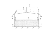
また、遮蔽板13をタンク側壁2と交差する方向に突出し且つその突出先端部を上方に折り曲げることにより、タンク側壁2に沿って上昇する風だけでなく、カバー11のタンク側壁側開口部12に吹込む横風も通気穴10に流入するのを抑制することができ、環境負荷をより一層低減することが可能となる。
なお、通気穴10の形状、カバー11の形状、遮蔽板13の形状は、実施形態に限定されるものではない。また、通気口構造9のタンク屋根3への設置数も実施形態に限定されるものではない。
2 側壁
3 屋根
4 浮蓋
5 フロート
6 シール
7 吸引配管
8 窒素配管
9 通気口構造
10 通気穴
11 カバー
12 開口部
13 遮蔽板
14 上昇風遮蔽部
15 横風遮蔽部
Claims (4)
- 蒸発する液体を貯留し且つ側壁と屋根を有するタンクの通気口構造であって、
前記屋根のうち前記側壁近傍に形成された通気穴と、
前記通気穴の少なくとも上方を覆い、少なくとも前記側壁側が開口するカバーと、
前記カバーの前記側壁側開口部の下方から、前記側壁と交差する方向に突設された遮蔽板と、
を備えたタンク用通気口構造。 - 前記遮蔽板は、前記側壁垂直方向から見た前記カバーの前記側壁側開口部の幅以上の幅を有することを特徴とする請求項1に記載のタンク用通気口構造。
- 前記遮蔽板は、前記側壁と交差する方向に突出し且つその突出先端部が上方に折り曲げられていることを特徴とする請求項1又は2に記載のタンク用通気口構造。
- 前記遮蔽板のうち前記上方に折り曲げられた部分は、前記側壁垂直方向から見た前記カバーの前記側壁側開口部を覆うことを特徴とする請求項3に記載のタンク用通気口構造。
Priority Applications (1)
| Application Number | Priority Date | Filing Date | Title |
|---|---|---|---|
| JP2016025505A JP6572152B2 (ja) | 2016-02-15 | 2016-02-15 | タンク用通気口構造 |
Applications Claiming Priority (1)
| Application Number | Priority Date | Filing Date | Title |
|---|---|---|---|
| JP2016025505A JP6572152B2 (ja) | 2016-02-15 | 2016-02-15 | タンク用通気口構造 |
Publications (2)
| Publication Number | Publication Date |
|---|---|
| JP2017145008A true JP2017145008A (ja) | 2017-08-24 |
| JP6572152B2 JP6572152B2 (ja) | 2019-09-04 |
Family
ID=59682609
Family Applications (1)
| Application Number | Title | Priority Date | Filing Date |
|---|---|---|---|
| JP2016025505A Active JP6572152B2 (ja) | 2016-02-15 | 2016-02-15 | タンク用通気口構造 |
Country Status (1)
| Country | Link |
|---|---|
| JP (1) | JP6572152B2 (ja) |
Citations (2)
| Publication number | Priority date | Publication date | Assignee | Title |
|---|---|---|---|---|
| JPS5441367Y2 (ja) * | 1976-10-05 | 1979-12-04 | ||
| JP2010273429A (ja) * | 2009-05-20 | 2010-12-02 | Mitsubishi Electric Corp | 発電装置 |
-
2016
- 2016-02-15 JP JP2016025505A patent/JP6572152B2/ja active Active
Patent Citations (2)
| Publication number | Priority date | Publication date | Assignee | Title |
|---|---|---|---|---|
| JPS5441367Y2 (ja) * | 1976-10-05 | 1979-12-04 | ||
| JP2010273429A (ja) * | 2009-05-20 | 2010-12-02 | Mitsubishi Electric Corp | 発電装置 |
Also Published As
| Publication number | Publication date |
|---|---|
| JP6572152B2 (ja) | 2019-09-04 |
Similar Documents
| Publication | Publication Date | Title |
|---|---|---|
| US10598396B2 (en) | Floating-type humidifier container | |
| FI65468C (fi) | Takbrunn eller liknande foer en byggnad | |
| JP5747152B2 (ja) | 換気用ベントキャップ | |
| JP6488121B2 (ja) | 燃料タンク用弁装置 | |
| US9441751B2 (en) | Air pipe head | |
| JP6572152B2 (ja) | タンク用通気口構造 | |
| KR20110017182A (ko) | 화물창용 슬로싱 저감 구조판 | |
| JP2017137071A (ja) | 浮屋根式タンクの自動空気抜き | |
| US3123249A (en) | Venting arrangements for storage tanks | |
| US10746431B2 (en) | Air vent structure and box-type inverter having the same | |
| JP5034658B2 (ja) | 浮き屋根式タンクのスロッシング抑制装置 | |
| JP6919184B2 (ja) | 空気抵抗低減装置 | |
| US3167203A (en) | Tank for the storage of oil, gasoline and similar liquids on a water bed | |
| KR101373868B1 (ko) | 배수지의 환기구 | |
| JP2020193040A (ja) | 浮屋根式タンクの自動空気抜き | |
| JP5937654B2 (ja) | 排水トラップ装置 | |
| JP5007081B2 (ja) | 浮屋根式タンク及び浮屋根式タンクのウェザーシール装置 | |
| CN205266079U (zh) | 一种广播设备的外壳及广播设备 | |
| US10160406B2 (en) | Mobile platform and operating method thereof | |
| JPS6034465A (ja) | 貯槽用泡消火装置 | |
| CN216950534U (zh) | 一种低浓度瓦斯发电机组排气系统排气管的防雨装置 | |
| CN214690743U (zh) | 防渗漏托盘的限位式垫板 | |
| KR102690283B1 (ko) | 에어벤트 겸용 구스넥 타입 맨홀 | |
| CN208054088U (zh) | 一种集装箱 | |
| US5845676A (en) | Ballast tank device |
Legal Events
| Date | Code | Title | Description |
|---|---|---|---|
| A621 | Written request for application examination |
Free format text: JAPANESE INTERMEDIATE CODE: A621 Effective date: 20180314 |
|
| A977 | Report on retrieval |
Free format text: JAPANESE INTERMEDIATE CODE: A971007 Effective date: 20190116 |
|
| A131 | Notification of reasons for refusal |
Free format text: JAPANESE INTERMEDIATE CODE: A131 Effective date: 20190212 |
|
| A521 | Request for written amendment filed |
Free format text: JAPANESE INTERMEDIATE CODE: A523 Effective date: 20190313 |
|
| TRDD | Decision of grant or rejection written | ||
| A01 | Written decision to grant a patent or to grant a registration (utility model) |
Free format text: JAPANESE INTERMEDIATE CODE: A01 Effective date: 20190806 |
|
| A61 | First payment of annual fees (during grant procedure) |
Free format text: JAPANESE INTERMEDIATE CODE: A61 Effective date: 20190809 |
|
| R150 | Certificate of patent or registration of utility model |
Ref document number: 6572152 Country of ref document: JP Free format text: JAPANESE INTERMEDIATE CODE: R150 |