JP2017145169A - Production method and device of mercury sulfide - Google Patents
Production method and device of mercury sulfide Download PDFInfo
- Publication number
- JP2017145169A JP2017145169A JP2016028067A JP2016028067A JP2017145169A JP 2017145169 A JP2017145169 A JP 2017145169A JP 2016028067 A JP2016028067 A JP 2016028067A JP 2016028067 A JP2016028067 A JP 2016028067A JP 2017145169 A JP2017145169 A JP 2017145169A
- Authority
- JP
- Japan
- Prior art keywords
- mercury
- pot
- mercury sulfide
- cooling
- grinding
- Prior art date
- Legal status (The legal status is an assumption and is not a legal conclusion. Google has not performed a legal analysis and makes no representation as to the accuracy of the status listed.)
- Pending
Links
Images


Landscapes
- Crushing And Grinding (AREA)
Abstract
【課題】廃棄物として回収された水銀の硫化水銀化による安定化方法、及びその製造装置の提供。【解決手段】水銀と硫黄を粉砕工程によって反応させ、硫化水銀を製造する方法であって、前記反応工程中に冷却を行う硫化水銀の製造方法。内部に粉砕用の複数の金属製ボールを有した粉砕用ポット1と、粉砕用ポット1を振動させるバイブレーター5を備え、粉砕用ポット1は、冷媒によって冷却するための冷却機構6,7を備える硫化水銀の製造装置。【選択図】図5[Problem] To provide a method for stabilizing mercury recovered as waste by converting it into mercury sulfide, and a manufacturing apparatus for the same. [Solution] A method for producing mercury sulfide by reacting mercury and sulfur in a grinding process, in which cooling is performed during the reaction process. The mercury sulfide manufacturing apparatus includes a grinding pot 1 having multiple metal balls for grinding inside, and a vibrator 5 for vibrating the grinding pot 1, and the grinding pot 1 is equipped with cooling mechanisms 6 and 7 for cooling using a refrigerant. [Selected Figure] Figure 5
Description
本発明は、水銀と硫黄を反応させ、安定した硫化水銀を製造するための、硫化水銀の製造方法及び装置に関するものである。 The present invention relates to a method and apparatus for producing mercury sulfide for reacting mercury and sulfur to produce stable mercury sulfide.
本発明に係る硫化水銀の製造方法及び装置は、廃棄物として回収された水銀についての安定化の要請から生まれたものである。近年、日本国内では、水銀需要量を回収量が大きく上回っている。また、世界的には、水銀の輸出入が制限していく傾向にあり、将来的には膨大な量の余剰が発生する可能性がある。そのため、余剰分の水銀を長期間安定的に保存するための、水銀の安定化方法の確立が求められてきた。 The method and apparatus for producing mercury sulfide according to the present invention was born from a request for stabilization of mercury recovered as waste. In recent years, the amount of recovered products in Japan has greatly exceeded the amount of mercury demand. In addition, the global import and export of mercury tends to be restricted, and a huge amount of surplus may occur in the future. Therefore, it has been required to establish a mercury stabilization method for stably storing surplus mercury for a long period of time.
水銀(Hg)を安定化させる方法の1つとしては、粉砕工程において液体の水銀を粉体の硫黄(S)と反応(メカノケミカル反応)させることで、硫化水銀(HgS)を製造し、更にセメントと混合して固化させるという方法がある。 One method of stabilizing mercury (Hg) is to produce mercury sulfide (HgS) by reacting liquid mercury with powdered sulfur (S) (mechanochemical reaction) in the pulverization step, There is a method of solidifying by mixing with cement.
例えば、特許文献1によれば、ボールミルによる粉砕工程によって、水銀と硫黄を反応させて硫化水銀を製造し、その後更に砂利、砂、炭酸カルシウム、硫黄、硫黄ポリマーを混ぜて高温で反応させ、硫黄ポリマーセメントとして固化させることで安定化を行っている。
For example, according to
しかしながら、この方法においては、最終的に固化したセメントの状態における安定化を目的としており、その過程で製造される硫化水銀の安定性については何ら考慮されていなかった。 However, this method is aimed at stabilization in the state of cement finally solidified, and no consideration has been given to the stability of mercury sulfide produced in the process.
また、引用文献1において開示された方法においては、遊星ミルを使用して硫化水銀を製造しているが、その装置では比較的少量(100g程度)の水銀しか取り扱うことができない。また、その装置の構造は複雑であるため、大型化は難しい。したがって、年間約100トン程度の水銀を効率よく安定化させるためには、数キロ〜数トン単位といった多量の水銀を一度に反応させることができる安価で簡便な装置が必要である。
In the method disclosed in the cited
以上のような事情に対して、本発明の目的は、水銀と硫黄を粉砕工程により反応させ、安定した硫化水銀を製造することができるようにした硫化水銀の製造方法及び装置を提供することにある。 In view of the circumstances as described above, an object of the present invention is to provide a method and apparatus for producing mercury sulfide that allows mercury and sulfur to react in a pulverization step to produce stable mercury sulfide. is there.
前記目的を達成するため、本発明に係る硫化水銀の製造方法は、水銀と硫黄を粉砕工程によって反応させ、硫化水銀を製造する方法であって、前記反応工程中に冷却を行うことを特徴とする。 In order to achieve the above object, a method for producing mercury sulfide according to the present invention is a method for producing mercury sulfide by reacting mercury and sulfur in a pulverization step, wherein cooling is performed during the reaction step. To do.
また、前記粉砕工程は、粉砕用のボールを内蔵する粉砕機によって実施するもであってもよい。 The pulverization step may be performed by a pulverizer that incorporates a ball for pulverization.
また、前記冷却は、少なくとも前記粉砕工程における前記粉砕用のボールの衝突及び摩擦による温度上昇を緩和する程度の冷却とすることができる。 In addition, the cooling can be at least a degree of cooling that reduces a temperature increase due to collision and friction of the balls for grinding in the grinding step.
また、前記冷却工程は、前記粉砕機の外壁を冷媒によって冷却するものであってもよい。なお、ここでいう冷媒とは、対象である粉砕機の外壁から熱を奪うための液体または気体を意味する。 The cooling step may cool the outer wall of the pulverizer with a refrigerant. In addition, a refrigerant | coolant here means the liquid or gas for taking heat away from the outer wall of the grinder which is object.
また、本発明は、別の側面で硫化水銀を製造するための製造装置であり、該装置は、内部に粉砕用の複数の金属製ボールを有した粉砕用ポットと、該粉砕用ポットを振動させるバイブレーターとを備え、前記粉砕用ポットは、水冷によって冷却するための冷却機構を備える。 Further, the present invention is a manufacturing apparatus for manufacturing mercury sulfide according to another aspect, and the apparatus vibrates the grinding pot having a plurality of metal balls for grinding inside, and the grinding pot. And the pulverizing pot includes a cooling mechanism for cooling by water cooling.
本発明によれば、水銀と硫黄を粉砕工程により反応させ、安定した硫化水銀を製造することができる硫化水銀の製造方法及び装置が提供される。 ADVANTAGE OF THE INVENTION According to this invention, the manufacturing method and apparatus of mercury sulfide which can react mercury and sulfur by a grinding | pulverization process and can manufacture the stable mercury sulfide are provided.
まず、本発明に係る硫化水銀の製造方法により製造する、硫化水銀の安定性の評価方法及び評価基準を説明する。 First, the stability evaluation method and evaluation criteria for mercury sulfide produced by the method for producing mercury sulfide according to the present invention will be described.
まず、本発明に係る硫化水銀の製造方法は、所定の安定性水準を満たす硫化水銀を製造するための方法である。得られる硫化水銀の評価方法としては、2013年にジュネーブで署名された「水銀に関する水俣条約(the Minamata Convention on Mercury)」の批准にともない硫化水銀を最終的に埋立処分することを想定して、環境省が告示した埋立処分を行う産業廃棄物の検定方法(環境庁告示13号)による評価が一般的に採用されている。 First, the method for producing mercury sulfide according to the present invention is a method for producing mercury sulfide that satisfies a predetermined stability level. As a method of evaluating the resulting mercury sulfide, it is assumed that the mercury sulfide will be finally landfilled with the ratification of the Minamata Convention on Mercury signed in Geneva in 2013. The evaluation based on the inspection method of industrial waste for landfill disposal announced by the Ministry of the Environment (Environment Agency Notification No. 13) is generally adopted.
この環境庁告示第13号では、硫化水銀等の安定性の検定方法が規定されている。この告示によれば、試験対象である硫化水銀の粉体50g(粒径0.5mm〜5mm)を、溶媒である純水(JIS K 0557の示すA3、又は、A4の水)500mlに投入し、200回/分の周期で6時間水平振とうさせる。その後、遠心加速度3000Gの条件で、20分間遠心分離を行い、溶出液を採取する。そして、その溶出液を孔径1μmのメンブランフィルターを用いて濾過し、濾過後の検液について成分の分析を行い、水銀の溶出値を測定している。安定した硫化水銀を製造することができない場合、この試験においては未反応の水銀が基準値より多く溶出してしまうため、好ましくない。尚、本発明者らは、環境庁告示第13号による試験に基づいて、液体中に溶出する水銀の濃度が0.005mg/L以下であることを基準として、硫化水銀の評価を行うことにより、鋭意検討を積み重ねてきた。 This Environmental Agency Notification No. 13 stipulates a method for testing the stability of mercury sulfide and the like. According to this notice, 50 g of mercury sulfide powder (particle size: 0.5 mm to 5 mm) to be tested is put into 500 ml of pure water (A3 or A4 water shown by JIS K 0557) as a solvent. , Shake horizontally for 6 hours at a cycle of 200 times / minute. Thereafter, centrifugation is performed for 20 minutes under the condition of a centrifugal acceleration of 3000 G, and the eluate is collected. Then, the eluate is filtered using a membrane filter having a pore size of 1 μm, the components of the test solution after filtration are analyzed, and the elution value of mercury is measured. In the case where stable mercury sulfide cannot be produced, unreacted mercury is eluted in this test more than the standard value, which is not preferable. In addition, based on the test by Environment Agency Notification No. 13, the present inventors evaluated mercury sulfide on the basis that the concentration of mercury eluted in the liquid is 0.005 mg / L or less. , Have earnestly studied.
尚、硫化水銀の安定性を評価する方法の一つとしてヘッドスペース試験も用いられる。環境庁告示第13号の試験は、水銀の水への溶出性を評価する方法であるのに対し、ヘッドスペース試験は、水銀の大気中への拡散度合いを評価する方法である。このヘッドスペース試験の具体的な方法としては、まず、硫化水銀(10g)を、120mlの広口共栓瓶の底に一様分布するように入れる。そして、瓶にガス流入及び流出のための2本の管を有したゴム栓で蓋をする。その後、一方の管から1l/minの流速でガスを通気させ、他方の管から排出されたガス中の水銀濃度を測定する。この測定を、湿度60%で、10℃、25℃、30℃、40℃、70℃のような各温度条件で行う。70℃で実施する際には、硫化水銀の処分時の環境条件を想定し、窒素ガス雰囲気中で試験を行っている。尚、本発明者らは、気体中で測定される水銀の濃度が0.001mg/m3以下であることを基準として、硫化水銀の評価を行うことにより、鋭意検討を積み重ねてきた。 A head space test is also used as one of the methods for evaluating the stability of mercury sulfide. The Environmental Agency Notification No. 13 test is a method for evaluating the elution of mercury into water, while the headspace test is a method for evaluating the degree of diffusion of mercury into the atmosphere. As a specific method of this head space test, first, mercury sulfide (10 g) is introduced so as to be uniformly distributed on the bottom of a 120 ml wide-mouthed stopper bottle. Then, the bottle is covered with a rubber stopper having two pipes for gas inflow and outflow. Thereafter, gas is passed through one pipe at a flow rate of 1 l / min, and the mercury concentration in the gas discharged from the other pipe is measured. This measurement is performed at a humidity of 60% and under various temperature conditions such as 10 ° C., 25 ° C., 30 ° C., 40 ° C., and 70 ° C. When implemented at 70 ° C., the test is performed in a nitrogen gas atmosphere assuming environmental conditions at the time of disposal of mercury sulfide. In addition, the present inventors have accumulated earnestly examination by evaluating mercury sulfide on the basis that the concentration of mercury measured in gas is 0.001 mg / m 3 or less.
以下に、本発明に係る硫化水銀の製造方法及び装置の実施の形態を、添付図面を参照しながら詳細に説明する。 Hereinafter, embodiments of a method and apparatus for producing mercury sulfide according to the present invention will be described in detail with reference to the accompanying drawings.
[第1の実施形態]
まず、図1〜6を用いて、第1の実施形態に係る硫化水銀の製造方法及び製造装置について説明する。
[First Embodiment]
First, the manufacturing method and manufacturing apparatus of mercury sulfide according to the first embodiment will be described with reference to FIGS.
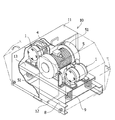
図1〜3に、水銀及び硫黄を衝撃・摩擦・せん断・圧縮エネルギーによって反応させ、硫化水銀を製造するための粉砕装置10を示している。該粉砕装置10は、本発明に係る硫化水銀の製造装置の一実施の形態を構成する。粉砕装置10は、中心に振動用のバイブレーター5を備えている。バイブレーター5は、内部にモーターを有しており、耐震ケーブル12を介して外部から電力が供給される。また、バイブレーター5の軸端51の内部には、モーターの軸端部に、軸心に対してアンバランスに設置されたウェイトを備えている。これにより、モーターの回転によって、振動を発生させる構造となっている。
1 to 3 show a
また、図4は、粉砕装置10に搭載する粉砕用ポット1を装置から外したものを示している。この図4に示すように、蓋16及び容器15を備えている。また、蓋16を固定具17でねじ止めすることによって、粉砕用ポット1の蓋16を容器15に固定している。内部には、金属製のボールが複数個入っている。本粉砕装置10を使用する際には、この粉砕用ポット内に、更に液体の水銀及び粉体の硫黄を封入する。
FIG. 4 shows the
バイブレーター5は、振動ステージ13に固定されており、また、この振動ステージ13は接地面に固定されたベース8に、スプリング9を介して固定されている。更に、振動ステージ13上には、粉砕用ポット1及が、バイブレーター5を挟んで均等な位置に固定されている。この粉砕用ポット1は、バイブレーター5の両側に均等に配置されることで、振動時におけるバランスを取り、振動の動作及び振動幅を安定させる効果を期待できる。また、粉砕用ポットは、留め具4によって、しっかりと振動ステージ13に固定されている。
The
尚、本粉砕装置10は、作動時に比較的大きな作動音が発生するため、所定の遮音性能を備えた開閉式のカバー11によって装置全体を覆うことができる構造となっている。カバー11は、図2における左右方向に開閉する仕組みとなっている。
The pulverizing
図5に示すように、粉砕装置10には、粉砕用ポット1の外壁面を冷却するための空冷式の冷却装置6を設置することが可能となっている。冷却装置6では、カバー11の外部に設けたファン61によって空気を送り込み、ダクト62を介して、粉砕用ポット1の外壁に送り込んだ空気を当てることで、粉砕用ポット1を冷却する機構となっている。また、カバー11内に設けてある非接触式のセンサー63によって粉砕用ポット1の外壁の温度を測定する。更に、測定した温度データを、カバー11の外に設けたPLC(programmable logic controller)64に送り、PLCからの制御信号を、インバーター65を介してファン61に送ることで、ファン61の動作を制御している。ファン61の動作は、センサー63の値が所定の閾値を超えると開始するようになっている。また、閾値を段階的に設定し、温度に応じてファン61の運転速度を段階的に高めるように設定することも可能となっている。尚、粉砕用ポット1の外壁の温度は、カバー11の外に設けた表示器66に表示されるため、操作者が確認することができるようになっている。
As shown in FIG. 5, an air-cooling
また、図6に示すように、粉砕装置10には、粉砕用ポット1の外壁面を冷却するための水冷式の冷却装置7を設置することも可能となっている。冷却装置7では、カバー11の外部に設けたポンプ71によって冷却水をくみ上げ、ダクト72を介してくみ上げた冷却水を粉砕用ポット1の外壁に当てることで、粉砕用ポット1を冷却する機構となっている。また、カバー11内に設けてある非接触式のセンサー73によって粉砕用ポット1の外壁の温度を測定する。更に、測定した温度データを、カバー11の外に設けたPLC(programmable logic controller)74に送り、PLCからの制御信号を、インバーター75を介してポンプ71に送ることで、ポンプ71の動作を制御している。ポンプ71の動作は、センサー73の値が所定の閾値を超えると開始するようになっている。また、閾値を段階的に設定し、温度に応じてポンプ71の運転速度を段階的に高めるように設定することも可能となっている。尚、粉砕用ポット1の外壁の温度は、カバー11の外に設けた表示器76に表示されるため、操作者が確認することができるようになっている。また、粉砕用ポット1の外壁に当てられた冷却水は、排出ダクト77によって回収容器78に回収される。そして、回収容器78に回収された冷却水は、冷却器79によって再度冷却され、冷却水容器80に供給される。このように、一旦使用した冷却水は回収され、再利用することができる機構となっている。尚、冷却器79と同様の冷却器を、さらにポンプダクト71に設けることもできる。冷却器を複数個所に設けることによって、冷却水の冷却性能を高めることができる。
As shown in FIG. 6, the pulverizing
以上のような構成を備える粉砕装置10の動作を説明することによって、本発明に係る硫化水銀の製造方法の一実施の形態を説明する。まず、耐震ケーブル12を介して電力を得たバイブレーター5が内蔵したモーターによって振動する。バイブレーター5によって振動のエネルギーを受けた振動ステージ13は、スプリング9を介してベース8と固定しているため、ベース8とは独立に、かつバイブレーター5と一体に振動する。更に、振動ステージ13に固定された粉砕用ポット1も、振動ステージ13と一体に振動する。
An embodiment of the method for producing mercury sulfide according to the present invention will be described by explaining the operation of the pulverizing
粉砕用ポット1が振動することで、内部に封入された金属製のボールが様々な方向に運動し、同封された水銀及び硫黄を攪拌しながら粉砕する。この粉砕によって生じる衝撃・摩擦・せん断・圧縮エネルギーにより、水銀及び硫黄が反応し、硫化水銀が製造される。本実施の形態における粉砕装置10は回転する構造の粉砕装置と比較して、粉砕対象物に対して効率よくより大きなエネルギーを加えることができる。そのため、比較的多量の水銀を、一度に取り扱うことができる。
When the crushing
ここで、上述した粉砕の工程においては、金属のボールには、粉砕用ポット1の内部で、他のボール、粉砕用ポットの内壁面、反応前の水銀及び硫黄、反応後の硫化水銀との間で激しく衝突及び摩擦が生じる。これにより、粉砕用ポット1の内部は、非常に高温(例えば100℃以上)となる。このように非常に高温な状況で硫化水銀を製造した場合、上述した試験方法による評価において、本発明者らは、硫化水銀の安定性が低下するという傾向を見出した。
Here, in the pulverization step described above, the metal balls are mixed with other balls, the inner wall surface of the pulverization pot, mercury and sulfur before reaction, and mercury sulfide after reaction inside the
尚、このような温度上昇現象は、従来の方法では問題とされてこなかった。従来の方法では、取り扱う水銀の量は、数100g程度であり、本実施の形態で説明したような高エネルギーの粉砕方法は必要とされてこなかったため、主に粉砕用ポットを縦方向、又は、横方向に回転させる方法がとられてきたためである。この場合、粉砕用のボールの衝突のエネルギーは比較的小さく、温度の上昇量は、比較的少なかったと考えられる。これに対し、本実施の形態に係る製造方法では、対象とする水銀の取扱量が数キロ〜数トンと大量であり、この大量の水銀を効率よく処理するために、より高エネルギーで粉砕工程を実施できる構成となっており、これに伴い、発生する熱量も膨大となっている。 Such a temperature rise phenomenon has not been a problem in the conventional method. In the conventional method, the amount of mercury to be handled is about several hundred grams, and the high energy pulverization method as described in the present embodiment has not been required. This is because a method of rotating in the horizontal direction has been taken. In this case, it is considered that the energy of collision of the balls for pulverization was relatively small, and the amount of temperature increase was relatively small. On the other hand, in the manufacturing method according to the present embodiment, the amount of mercury handled is as large as several kilos to several tons, and in order to efficiently process this large amount of mercury, the pulverization step with higher energy As a result, the amount of heat generated is enormous.
そこで、本実施の形態においては、粉砕工程において、前述した注水装置によって、粉砕用ポット1の外壁面を冷却している。これにより、粉砕工程中に温度が上昇する粉砕用ポット1の外壁を冷却し、間接的に粉砕用ポット1の内部を冷却している。
Therefore, in the present embodiment, in the pulverization step, the outer wall surface of the
粉砕工程中に、このような冷却を行うことで、製造された硫化水銀は、前述した環境庁告示第13号の試験、及び、ヘッドスペース試験による安定性評価が、良好なものとなる。 By performing such cooling during the pulverization process, the manufactured mercury sulfide is evaluated by the environmental agency notification No. 13 and the stability evaluation by the head space test.
尚、本実施の形態における粉砕用ポット1の温度の測定方法としては、ポットの外壁のうち容器底部などの温度を非接触式の温度計(例えば、赤外線や可視光線を用いて測定を行う放射温度計)や、接触式の温度計(例えば、熱電対)にて測定することができる。このように、粉砕工程中のポット内部の温度を測定する方法としては、外壁(例えば開封面と反対側の底面)の表面温度から推定する方法を採用することができる。例えば、粉砕用ポット1内部の温度上昇と、ポット外壁面の特定箇所の温度上昇の関係をあらかじめ確認し、それぞれの相関を把握しておくことで、ポット内部の温度をより容易に管理することができる。
As a method for measuring the temperature of the crushing
[第2の実施形態]
図7〜8を用いて、第2の実施形態に係る硫化水銀の製造方法及び装置について説明する。尚、本第2の実施形態は、第1の実施形態(図1〜6)の変形例であるため、同一部分、又は、類似部分については、重複する説明を省略し、相違点について、詳細に説明する。
[Second Embodiment]
A method and apparatus for producing mercury sulfide according to the second embodiment will be described with reference to FIGS. Since the second embodiment is a modification of the first embodiment (FIGS. 1 to 6), the same or similar parts will not be described repeatedly, and the differences will be described in detail. Explained.
本第2の実施形態においては、第1の実施形態で示したように冷媒を粉砕用ポットに当てて冷却する代わりに、冷却機構を設けることで、粉砕用ポットを、より効率よく冷却できるようにしている。 In the second embodiment, instead of cooling the pulverizing pot by applying the coolant to the pulverizing pot as shown in the first embodiment, a cooling mechanism is provided so that the pulverizing pot can be cooled more efficiently. I have to.
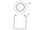
まず、図7は、本第2の実施形態に係る粉砕用ポットの容器25の断面図及び蓋の図である。図7に示すように、蓋26及び容器は着脱可能に作られている。
First, FIG. 7 is a sectional view of a
一方、図8には、図7で示した粉砕用ポットの容器25の内部に、冷却機構を追加したものを示している。詳細には、容器25の胴体部分の外壁21の内側に、内壁22を設けている。これにより、外壁21と内壁22との間に隙間ができ、冷媒を注入するスペースが確保される。更に、このスペースには、注入および排出用のパイプ24が備えられている。このパイプ24は、蓋16を容器25に固定する際は、蓋16に設けられた孔23に通される。
On the other hand, FIG. 8 shows an example in which a cooling mechanism is added inside the
このように、冷却機構を設けることにより、容器25の胴体部分の全面に渡って冷媒が供給され、粉砕工程によって熱が生じた容器内部を効果的に冷却することができる。また、一方のパイプ24から注入された冷媒は、他方のパイプ24から回収することができる。更に、粉砕工程においては、容器25の壁面が2重構造となり、内部に空間も介在するため、内部で発生した騒音の遮断効果も期待できる。また、回収される冷媒は高温となるため、熱エネルギーを回収し、その他の目的に利用することもできる。
Thus, by providing the cooling mechanism, the refrigerant is supplied over the entire body portion of the
尚、本第2の実施形態においても、粉砕用ポットの外壁の温度を測定することで、内部の温度を推定することが可能である。ここで、本第2の実施形態によれば、冷却機構は容器25の胴体部分に設けられているため、胴体部分の外壁の温度は、容器内部の温度と対応関係にない可能性があり、好ましくない。しかしながら、容器底部には、冷却機構が設けられていないため、この容器底部の温度を測定することで、容器内部の温度を推定することができる。
In the second embodiment as well, the internal temperature can be estimated by measuring the temperature of the outer wall of the grinding pot. Here, according to the second embodiment, since the cooling mechanism is provided in the body portion of the
また、本第2の実施形態においては、冷却に使用した冷媒は、パイプ24を介して回収することができる。そこで、この回収した冷媒の温度及び流量を観測することで、冷却水が粉砕装置から奪った熱量を推定することができる。
In the second embodiment, the refrigerant used for cooling can be recovered via the
このようにして得られた温度や熱量のデータが、冷却機構を制御するコントローラーに送信されることで、コントローラーが、粉砕装置の効果的な冷却操作を制御することができる。 The temperature and heat quantity data thus obtained is transmitted to the controller that controls the cooling mechanism, so that the controller can control the effective cooling operation of the pulverizer.
[第3の実施形態]
図9〜11を用いて、第3の実施形態に係る硫化水銀の製造方法及び装置について説明する。尚、本第3の実施形態は、第1の実施形態及び第2の実施形態の変形例であるため、同一部分、又は、類似部分については、重複する説明を省略し、相違点について、詳細に説明する。
[Third Embodiment]
A method and apparatus for producing mercury sulfide according to the third embodiment will be described with reference to FIGS. Since the third embodiment is a modification of the first embodiment and the second embodiment, the same or similar portions will not be described repeatedly, and the details of the differences will be described. Explained.
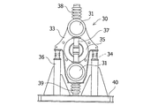
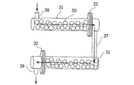
図9は、本発明に係る硫化水銀の製造方法に用いる製造装置の一態様である、粉砕装置30を示している。この図9に示すように、第3の実施形態に係る粉砕装置30は、中心部にバイブレーター35を備え、その上下に粉砕用ポット31を各1個備えている。バイブレーター35及び粉砕用ポット31はサポート33によって一体に固定されている。サポート33は、図9中の左右両端下側においてサイドスプリング34の上端で支持されている。サイドスプリング34は、下端がそれぞれ支柱36の上端に固定されている。また、支柱36の下端は、ベース40に固定されている。
FIG. 9 shows a pulverizing
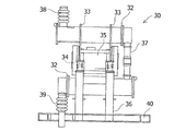
バイブレーター35の上方に設けられた粉砕用ポット31の上部には、投入口38が設けられており、上部から粉砕用の水銀及び硫黄を投入することが可能となっている。また、バイブレーター35の下方に設けられた粉砕用ポット31には、その下部に排出口39が設けられている。更に、上方と下方の各粉砕用ポットは、ダクト37で接続されており、上方の粉砕用ポットから下方の粉砕用ポットへ、水銀、硫黄、硫化水銀等が流入可能な構造となっている。
A charging
また、図10に示すように、サポート33は、バイブレーターの軸方向の2か所に設けられている。更に、サポート33には、それぞれ2本のサイドスプリング34が設けられている。したがって、本実施の形態では、合計4本のサイドスプリング34が設置されている。一方、投入口38及び排出口39は、それぞれ、バイブレーター35の軸方向の、図9における図中後方寄りに設けられている。また、ダクト37は、バイブレーター35の軸方向の、図9における図中手前寄りに設けられている。
Moreover, as shown in FIG. 10, the
図9に示すように、以上のような構成によって、粉砕装置30は、以下のような動作をする。まず、バイブレーター35が、振動することで、一体に固定されたサポートと、上下の各粉砕用ポットと、これらに接続されたダクト37とが、一体に振動する。これにより、上下の粉砕用ポット内部に設けた粉砕用のボールが激しく運動する。このとき、投入口から、水銀及び硫黄を投入することで、上部の粉砕用ポット内で、これらが攪拌及び粉砕される。更に、水銀と硫黄と一部の製造済みの硫化水銀が、ダクト37を通って、下部の粉砕用ポットに移動し、より攪拌及び粉砕が促進される。尚、上下の粉砕用ポットには、しきり32が設けられており、粉砕用のボール50が粉砕用ポットの外部に出ないようになっている。また、このしきり32には、粉体や液体が通過できる程度の孔が設けられているため、水銀、硫黄、硫化水銀は通過することができるようになっている。
As shown in FIG. 9, the crushing
これらの工程によって、連続的に投入口38に投入された水銀及び硫黄が、装置内部で硫化水銀に生成され、排出口39から連続的に排出されることとなる。これにより、各粉砕用ポットを開閉して水銀及び硫黄を投入及び回収する手間が省け、効率的に硫化水銀を製造することができる。
Through these steps, mercury and sulfur continuously input to the
ここで、本第3の実施の形態においても、冷却機構を備えることができる。例えば、第1の実施形態に示したような、冷却装置6又は冷却装置7を設けて、各粉砕用ポットの外壁に冷媒を当てることで、粉砕用ポットを冷却することができる。また、第2の実施形態に示したように、各粉砕用ポットの胴体部分の壁面を2重構造とし、冷却用の空間を設けることができる。この空間に、外部に設けた冷媒の供給装置から冷媒を注入し、さらに排出させることで、粉砕用ポットの内部を冷却することができる。
Here, also in the third embodiment, a cooling mechanism can be provided. For example, the crushing pot can be cooled by providing the
本第3の実施形態における粉砕装置30は、前述した第1及び第2の実施形態における粉砕装置と比較し、連続的に硫化水銀の製造のための運転が可能である点が異なっている。そのため、運転を停止する機会が減り、装置が外気によって自然に冷却される時間が短くなる。これにより、粉砕用ポット31及びその内部の温度が、より高温となる可能性がある。しかしながら、上記のような冷却機構を設けることで、効率的な冷却を図ることができる。これにより、安定した硫化水銀を、連続的に製造することが可能となる。
The pulverizer 30 in the third embodiment is different from the pulverizers in the first and second embodiments described above in that the operation for continuously producing mercury sulfide is possible. Therefore, the opportunity to stop the operation is reduced and the time during which the device is naturally cooled by the outside air is shortened. Thereby, the
[その他の態様]
前述した実施形態の説明は、本発明に係る硫化水銀の製造方法及び装置を説明するための例示であって、特許請求の範囲に記載の発明を限定するものではない。また、本発明の各部構成は前述した実施形態に限らず、特許請求の範囲に記載の技術的範囲内で種々の変形が可能である。
[Other aspects]
The description of the embodiment described above is an example for explaining the method and apparatus for producing mercury sulfide according to the present invention, and does not limit the invention described in the claims. Moreover, each part structure of this invention is not restricted to embodiment mentioned above, A various deformation | transformation is possible within the technical scope as described in a claim.
例えば、金属製のボールは、本説明では、クロム鋼製のものを用いているが、鉄製、ステンレス製、セラミック製等のボールやロッド(棒)を用いることもできる。また、粉砕用ポットの素材には、ステンレスを用いて説明したが、冷却効率や衝撃に対する強度を考慮し、鉄、チタンを用いる等、適宜材質を変更することができる。更に、粉砕用ポットの外径や軸方向長さ、ボール外径、粉砕時間は、製造する硫化水銀の量に応じて適宜変更することができる。また、冷却に用いる冷媒としては、空気や水の他に、例えば冷却効率の高い液体窒素等を用いることもできる。また、エチレングリコールやグリセリンを主成分とする不凍液等を用いることで、寒冷地においても、冷却液の凍結を防ぐことができる。 For example, although the metal balls are made of chrome steel in this description, balls or rods (rods) made of iron, stainless steel, ceramic, etc. can be used. In addition, although the description has been made using stainless steel as the material for the pulverizing pot, the material can be appropriately changed such as using iron or titanium in consideration of cooling efficiency and strength against impact. Furthermore, the outer diameter, axial length, ball outer diameter, and pulverization time of the pulverizing pot can be appropriately changed according to the amount of mercury sulfide to be produced. In addition to air and water, for example, liquid nitrogen having a high cooling efficiency can be used as the refrigerant used for cooling. In addition, by using an antifreeze liquid mainly composed of ethylene glycol or glycerin, the cooling liquid can be prevented from freezing even in a cold region.
ここで、第1の実施の形態に係る硫化水銀の製造方法及び装置を実施し、冷却温度を検討した実施例を以下に示す。 Here, the example which implemented the manufacturing method and apparatus of the mercury sulfide which concerns on 1st Embodiment, and examined cooling temperature is shown below.
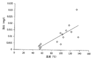
図12には本第1の実施形態において、粉砕工程における粉砕用ポットの温度を約140℃〜約55℃の範囲に制御して製造された硫化水銀について、環境庁告示第13号の試験により水銀溶出値を評価した結果を示している。この結果によれば、粉砕工程中に冷却を行うことで、溶出値が低くなる傾向がわかる。また、より好適には、粉砕用ポットの温度が60℃以下となると、製造された硫化水銀の安定性がより高まり、基準値である0.005mg/L以下となる傾向にある。尚、この試験においては、外径25mmのクロム製の粉砕用ボールを170個用い、1.5kgの水銀を45分間粉砕した。尚、本第1の実施例における冷却には、水冷式の冷却装置7を用いている。
FIG. 12 shows the mercury sulfide produced by controlling the temperature of the pulverizing pot in the pulverization step in the range of about 140 ° C. to about 55 ° C. in the first embodiment, according to the test of Environmental Agency Notification No. 13. The result of evaluating the mercury elution value is shown. According to this result, it can be seen that the elution value tends to decrease by cooling during the pulverization step. More preferably, when the temperature of the grinding pot is 60 ° C. or lower, the stability of the produced mercury sulfide is further increased and tends to be 0.005 mg / L or less, which is a reference value. In this test, 170 chrome grinding balls having an outer diameter of 25 mm were used and 1.5 kg of mercury was crushed for 45 minutes. Note that a water-cooled
尚、本第1の実施例では、純度99.9%、密度13.57kg/m3液体水銀(Hg)1000gに、かさ比重0.6の粉末状の硫黄(s)を混合し、各粉砕用ポット1に充填し、硫化水銀の製造を行った。尚、このとき水銀:硫黄のmol比は、1.0:1.05となっている。
In the first embodiment, powdery sulfur (s) having a bulk specific gravity of 0.6 was mixed with 1000 g of liquid mercury (Hg) having a purity of 99.9% and a density of 13.57 kg / m 3 , and pulverized. The
粉砕装置10に搭載されている粉砕用ポット1は、容器の胴体円周部分を外径165mm、内径135mm、深さ180mm、厚さ6.4mmのステンレス製の容器とし、内容量は、1ポットにつき3000mlとした。また、この粉砕用ポット1を振動させるためのモーターは、出力0.85kw、電源電圧200V、電源周波数50Hzを使用した。更に、カバー11の内部に設置された注水装置からは、約0℃の水を毎分250ml、各粉砕用ポット1の外壁部に供給する仕様となっている。
The crushing
次に、第2の実施の形態に係る硫化水銀の製造方法及び装置を使用し、クロム鋼製の粉砕用ボールの外径と、粉砕時間を検討した結果を以下に示す。 Next, the results of studying the outer diameter and grinding time of a chromium steel grinding ball using the method and apparatus for producing mercury sulfide according to the second embodiment are shown below.
ここで、本実施例2における、冷却水の供給量は、毎分4lとし、冷却水の水温は、約0℃とした。また、容器25内部の冷却水用の隙間の容量は0.7lとし、その内側に位置する粉砕用スペースの容量は2lとした。尚、内壁22の素材には、外壁21と同様のステンレスを用いた。また、パイプ24には、内径約3mm、外径約5mmの鉄製のパイプを用いた。
Here, the supply amount of the cooling water in Example 2 was 4 liters per minute, and the water temperature of the cooling water was about 0 ° C. The capacity of the gap for cooling water inside the
容器25の中に投入する粉砕用の金属ボールには、外径約25mmのクロム鋼製粉砕ボールを110個(7.2kg)用いた。
110 metal balls (7.2 kg) made of chromium steel having an outer diameter of about 25 mm were used as the metal balls for grinding put into the
本第2の実施例によれば、粉砕用のボールの外径と、粉砕時間には、安定した硫化水銀を得るために最適なパラメータが存在した。例えば、以下に示す表1では、粉砕用のボール外径と粉砕時間を変更して硫化水銀を製造した際の、外観評価結果、ヘッドスペース試験結果、環境庁告示第13号試験の評価結果を示す。ここでいう外観評価とは、反応生成物が好ましい粉末状態となっているかどうかを目視で評価したものをいう。尚、粉末状でない場合は液体の水銀と粉体の硫黄の反応中間体として、塊や銀白色のペースト状の物質が混在している状態となる。この外観評価の結果によれば、ボール外径はφ25が良好であり、粉砕時間は45分〜60分程度が良好であった。 According to the second example, optimum parameters for obtaining stable mercury sulfide existed in the outer diameter of the ball for grinding and the grinding time. For example, in Table 1 shown below, the appearance evaluation results, the head space test results, and the evaluation results of the Environmental Agency Notification No. 13 test when mercury sulfide is produced by changing the outer diameter of the ball for grinding and the grinding time are shown. Show. Appearance evaluation as used herein refers to visual evaluation of whether or not the reaction product is in a preferred powder state. When the powder is not in the form of powder, a lump or silver-white paste-like substance is mixed as a reaction intermediate of liquid mercury and powder sulfur. According to the results of this appearance evaluation, the ball outer diameter was good at φ25, and the grinding time was good at about 45 minutes to 60 minutes.

1 粉砕用ポット
4 留め具
5 バイブレーター
6 冷却装置
7 冷却装置
8 ベース
9 スプリング
10 粉砕装置
11 カバー
12 耐震ケーブル
13 振動ステージ
15 容器
16 蓋
17 固定具
21 外壁
22 内壁
23 孔
24 パイプ
25 容器
26 蓋
30 粉砕装置
31 粉砕用ポット
32 しきり
33 サポート
34 サイドスプリング
35 バイブレーター
36 支柱
37 ダクト
38 投入口
39 排出口
40 ベース
50 粉砕用のボール
51 軸端
61 ファン
62 ダクト
63 センサー
64 PLC
65 インバーター
66 表示器
71 ポンプ
72 ダクト
73 センサー
74 PLC
75 インバーター
76 表示器
77 排出ダクト
78 回収容器
79 冷却器
80 冷却水容器
DESCRIPTION OF
65
75
Claims (5)
該粉砕用ポットを振動させるバイブレーターを備え、
前記粉砕用ポットは、冷媒によって冷却するための冷却機構を備える硫化水銀の製造装置。 A crushing pot having a plurality of metal balls for crushing therein;
A vibrator that vibrates the grinding pot;
The pulverization pot is an apparatus for producing mercury sulfide provided with a cooling mechanism for cooling with a refrigerant.
Priority Applications (1)
| Application Number | Priority Date | Filing Date | Title |
|---|---|---|---|
| JP2016028067A JP2017145169A (en) | 2016-02-17 | 2016-02-17 | Production method and device of mercury sulfide |
Applications Claiming Priority (1)
| Application Number | Priority Date | Filing Date | Title |
|---|---|---|---|
| JP2016028067A JP2017145169A (en) | 2016-02-17 | 2016-02-17 | Production method and device of mercury sulfide |
Publications (1)
| Publication Number | Publication Date |
|---|---|
| JP2017145169A true JP2017145169A (en) | 2017-08-24 |
Family
ID=59682653
Family Applications (1)
| Application Number | Title | Priority Date | Filing Date |
|---|---|---|---|
| JP2016028067A Pending JP2017145169A (en) | 2016-02-17 | 2016-02-17 | Production method and device of mercury sulfide |
Country Status (1)
| Country | Link |
|---|---|
| JP (1) | JP2017145169A (en) |
Cited By (2)
| Publication number | Priority date | Publication date | Assignee | Title |
|---|---|---|---|---|
| JP2022083978A (en) * | 2020-11-25 | 2022-06-06 | ネッチュ トロッケンマールテヒニク ゲーエムベーハー | Method for producing homogenized mixture of carbon, sulfur and ptfe |
| JP2022546727A (en) * | 2019-09-06 | 2022-11-07 | レッチェ ゲゼルシャフト ミット ベシュレンクテル ハフツング | laboratory mill |
Citations (4)
| Publication number | Priority date | Publication date | Assignee | Title |
|---|---|---|---|---|
| JPS60119930U (en) * | 1984-01-20 | 1985-08-13 | 川崎重工業株式会社 | Batch type vibrating mill |
| JP2007007638A (en) * | 2005-05-31 | 2007-01-18 | Seiko Epson Corp | Grinding method, grinding device and powder |
| US20080019900A1 (en) * | 2004-06-03 | 2008-01-24 | Stimi Societe Des Techniques En Milieu Ionisant | Method For Stabilisation Of Metallic Mercury Using Sulphur |
| JP2013503729A (en) * | 2009-09-09 | 2013-02-04 | コンセホ・スペリオール・デ・インベスティガシオネス・シエンティフィカス | Method for stabilizing liquid mercury using sulfur polymer cement via mercury sulfide |
-
2016
- 2016-02-17 JP JP2016028067A patent/JP2017145169A/en active Pending
Patent Citations (4)
| Publication number | Priority date | Publication date | Assignee | Title |
|---|---|---|---|---|
| JPS60119930U (en) * | 1984-01-20 | 1985-08-13 | 川崎重工業株式会社 | Batch type vibrating mill |
| US20080019900A1 (en) * | 2004-06-03 | 2008-01-24 | Stimi Societe Des Techniques En Milieu Ionisant | Method For Stabilisation Of Metallic Mercury Using Sulphur |
| JP2007007638A (en) * | 2005-05-31 | 2007-01-18 | Seiko Epson Corp | Grinding method, grinding device and powder |
| JP2013503729A (en) * | 2009-09-09 | 2013-02-04 | コンセホ・スペリオール・デ・インベスティガシオネス・シエンティフィカス | Method for stabilizing liquid mercury using sulfur polymer cement via mercury sulfide |
Cited By (5)
| Publication number | Priority date | Publication date | Assignee | Title |
|---|---|---|---|---|
| JP2022546727A (en) * | 2019-09-06 | 2022-11-07 | レッチェ ゲゼルシャフト ミット ベシュレンクテル ハフツング | laboratory mill |
| JP7532507B2 (en) | 2019-09-06 | 2024-08-13 | レッチェ ゲゼルシャフト ミット ベシュレンクテル ハフツング | Laboratory Mill |
| US12259305B2 (en) | 2019-09-06 | 2025-03-25 | Retsch Gmbh | Laboratory mill |
| JP2022083978A (en) * | 2020-11-25 | 2022-06-06 | ネッチュ トロッケンマールテヒニク ゲーエムベーハー | Method for producing homogenized mixture of carbon, sulfur and ptfe |
| JP7307780B2 (en) | 2020-11-25 | 2023-07-12 | ネッチュ トロッケンマールテヒニク ゲーエムベーハー | Method for producing a homogenized mixture of carbon, sulfur and PTFE |
Similar Documents
| Publication | Publication Date | Title |
|---|---|---|
| CN105344428B (en) | A kind of wonderful mill prepared slices of Chinese crude drugs breaking cellular wall micronizing technique and its equipment | |
| JP5648640B2 (en) | Synthetic amorphous silica powder | |
| US20010016467A1 (en) | Method and apparatus for ultrafine grinding and/or mixing of solid particles | |
| CN106807511B (en) | A kind of graphite grazing crushing grinding device | |
| CN208427139U (en) | A kind of ball mill with cooling device | |
| JP2017145169A (en) | Production method and device of mercury sulfide | |
| CN108435288A (en) | A kind of hammer mill equipped with cushion socket | |
| JP2021508285A (en) | Equipment and methods for low temperature pulverization using a pulverization medium in the form of solidified low temperature gas | |
| Duc et al. | Investigation of melting point, Debye frequency and temperature of iron at high pressure | |
| AU2011335385A1 (en) | Method for the operation of a mill at continuous input and output mass flows | |
| CN106623951B (en) | A kind of oscillatory type deep cooling ball milling prepares the device and method of nanocrystalline powder | |
| CN205815857U (en) | A kind of novel disintegrating machine | |
| CN104923352B (en) | A kind of air hermetic pulverizer and its application | |
| CN204544346U (en) | A kind of food pulverizing device | |
| CN102776396B (en) | A preparation method of in-situ Mg2Si particle reinforced Mg-Al-Mn-Zn composite material semi-solid slurry | |
| CN104313501B (en) | Marine seamless motor shell | |
| JP2001334157A (en) | Fine grinding method of powder by low temperature vibration mill | |
| CN108481608A (en) | A kind of molding powder crushing improvement device | |
| Yukawa et al. | Raman scattering and lattice stability of NaAlH4 and Na3AlH6 | |
| CN204866016U (en) | Airtight type rubbing crusher | |
| JP2017144436A (en) | Rotor mill for directly or indirectly cooling the grinding chamber | |
| CN206215330U (en) | A kind of mechanical crushing equipment | |
| JP2008255007A (en) | High reactive slaked lime | |
| EP2323824B1 (en) | Device and method for cooling solid particles | |
| CN210332999U (en) | Iron ore magnetic separation device |
Legal Events
| Date | Code | Title | Description |
|---|---|---|---|
| A621 | Written request for application examination |
Free format text: JAPANESE INTERMEDIATE CODE: A621 Effective date: 20181129 |
|
| A977 | Report on retrieval |
Free format text: JAPANESE INTERMEDIATE CODE: A971007 Effective date: 20190822 |
|
| A131 | Notification of reasons for refusal |
Free format text: JAPANESE INTERMEDIATE CODE: A131 Effective date: 20190830 |
|
| A02 | Decision of refusal |
Free format text: JAPANESE INTERMEDIATE CODE: A02 Effective date: 20200303 |