JP2017145698A - Wind power generator - Google Patents
Wind power generator Download PDFInfo
- Publication number
- JP2017145698A JP2017145698A JP2016025811A JP2016025811A JP2017145698A JP 2017145698 A JP2017145698 A JP 2017145698A JP 2016025811 A JP2016025811 A JP 2016025811A JP 2016025811 A JP2016025811 A JP 2016025811A JP 2017145698 A JP2017145698 A JP 2017145698A
- Authority
- JP
- Japan
- Prior art keywords
- generator
- wind power
- housing
- windmill
- opening
- Prior art date
- Legal status (The legal status is an assumption and is not a legal conclusion. Google has not performed a legal analysis and makes no representation as to the accuracy of the status listed.)
- Pending
Links
Images


Classifications
-
- Y—GENERAL TAGGING OF NEW TECHNOLOGICAL DEVELOPMENTS; GENERAL TAGGING OF CROSS-SECTIONAL TECHNOLOGIES SPANNING OVER SEVERAL SECTIONS OF THE IPC; TECHNICAL SUBJECTS COVERED BY FORMER USPC CROSS-REFERENCE ART COLLECTIONS [XRACs] AND DIGESTS
- Y02—TECHNOLOGIES OR APPLICATIONS FOR MITIGATION OR ADAPTATION AGAINST CLIMATE CHANGE
- Y02E—REDUCTION OF GREENHOUSE GAS [GHG] EMISSIONS, RELATED TO ENERGY GENERATION, TRANSMISSION OR DISTRIBUTION
- Y02E10/00—Energy generation through renewable energy sources
- Y02E10/70—Wind energy
- Y02E10/72—Wind turbines with rotation axis in wind direction
Landscapes
- Wind Motors (AREA)
Abstract
Description
本発明は風力発電装置に関するものである。 The present invention relates to a wind power generator.
従来、この種の風力発電装置として特許文献1に開示されたものが知られている。特許文献1の風力発電装置は、複数の揚力型羽根を用いたものである。縦主軸の下部は、軸配設部の中央に設けた基台で支持され、基台の内部には、軸受、発電機、変圧器、自動制御器、回転速度センサ、自動ブレーキ手段、その他必要な機器装置等が配設されている。
Conventionally, what was disclosed by
ところで、風力発電装置は、風が発生する比較的厳しい自然環境で用いられるため、その構成部材を自然環境による劣化から可能な限り守る必要がある。
そこで、風力発電装置の基台周辺の構成部材を筐体により覆うことで保護することが考えられる。
By the way, since a wind power generator is used in a relatively severe natural environment where wind is generated, it is necessary to protect its constituent members from deterioration due to the natural environment as much as possible.
Therefore, it is conceivable to protect the components around the base of the wind power generator by covering them with a casing.
しかしながら、筐体により覆うと、発電機の発熱による熱がこもり、発電効率が低下してしまうおそれがあった。 However, if covered by the housing, heat generated by the heat generated by the generator may be accumulated, and power generation efficiency may be reduced.
本発明は、上記従来の実情に鑑みてなされたものであって、発電効率の低下を防止しつつ、構成部材の劣化も防止することを解決すべき課題としている。 This invention is made | formed in view of the said conventional situation, Comprising: It makes it the problem which should be solved to prevent deterioration of a structural member, preventing the fall of power generation efficiency.
本発明の風力発電装置は、
風車と、
前記風車の回転軸の回転によって発電する発電機と、
前記発電機を収容する筐体と、を備え、
前記筐体には、前記発電機が発する熱を外部へ放出する開口が設けられていることを特徴とする。
The wind power generator of the present invention is
With a windmill,
A generator for generating electricity by rotation of a rotating shaft of the windmill;
A housing for housing the generator,
The casing is provided with an opening for releasing heat generated by the generator to the outside.
本発明に係る風力発電装置は、発電機を収容する筐体を備え、筐体には、発電機が発する熱を外部へ放出する開口が設けられているから、以下の作用効果を奏する。すなわち、本発明に係る風力発電装置は、開口から熱を逃がすことにより、発電機の発熱による温度上昇を抑制して発電効率の低下を防ぐことができる。しかも、発電機は、筐体内に収納されているから、自然環境に晒されることによる性能劣化を可能な限り抑制することができる。 The wind turbine generator according to the present invention includes a housing that accommodates the generator, and the housing has an opening for releasing heat generated by the generator to the outside. That is, the wind power generator according to the present invention can prevent a decrease in power generation efficiency by suppressing a temperature rise due to heat generated by the generator by releasing heat from the opening. And since the generator is accommodated in the housing | casing, the performance degradation by being exposed to natural environment can be suppressed as much as possible.
本発明における好ましい実施の形態を説明する。 A preferred embodiment of the present invention will be described.
本発明の風力発電装置において、前記筐体内には、内部空間を区画する仕切り板が設けられており、前記仕切り板にて区画された複数の空間のうちの前記発電機が配置された空間を構成する外壁に、前記開口が備えられうる。この構成では、発電機の熱を開口から効率的に逃がし、発熱による影響の少ない部材は開口から隔てられて水や潮風等による錆の発生を防止することができる。 In the wind power generator of the present invention, a partition plate that partitions an internal space is provided in the housing, and a space in which the generator is arranged among a plurality of spaces partitioned by the partition plate. The opening may be provided in an outer wall constituting the structure. In this configuration, the heat of the generator is efficiently released from the opening, and the member that is less affected by the heat generation is separated from the opening, so that generation of rust due to water, sea breeze, or the like can be prevented.
本発明の風力発電装置において、前記風車の回転軸と、前記発電機の回転軸とを連結するためのカップリングと、前記風車の回転軸を停止させるためのブレーキ手段は、前記複数の空間のうちの前記発電機が配置された空間以外に配されることができる。この構成では、発電機の熱を開口から効率的に逃がし、熱を逃がす必要のないカップリング及びブレーキ手段は開口から隔てられて雨水や潮風等による錆の発生を防止することができる。 In the wind turbine generator according to the present invention, a coupling for connecting the rotating shaft of the windmill and the rotating shaft of the generator, and a brake means for stopping the rotating shaft of the windmill include the plurality of spaces. It can be arranged other than the space in which the generator is arranged. In this configuration, the heat of the generator is efficiently released from the opening, and the coupling and brake means that do not need to release the heat can be separated from the opening to prevent the occurrence of rust due to rainwater, sea breeze, or the like.
本発明の風力発電装置において、前記筐体には、前記風車の回転軸を回転可能に受ける軸受が取り付けられていてもよい。この構成では、発電機に軸受が備えられている場合と比べて、発電機を小型化することができる。また、軸受けが劣化した場合に、発電機を取り替えることなく、軸受のみを交換すれば良いからメンテナンスが容易となる。 In the wind turbine generator according to the present invention, a bearing that rotatably receives the rotating shaft of the windmill may be attached to the housing. In this configuration, the generator can be reduced in size compared to the case where the generator is provided with a bearing. Further, when the bearing is deteriorated, it is only necessary to replace the bearing without replacing the generator, so that maintenance is facilitated.
次に、本発明の風力発電装置を具体化した実施例について、図面を参照しつつ説明する。 Next, an embodiment embodying the wind power generator of the present invention will be described with reference to the drawings.
<実施例>
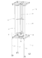
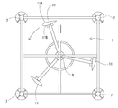
風力発電装置1は、風車3と、その下方に配された発電機5と、発電装置全体を支えるための支柱7とを備えている。この風力発電装置1は、いわゆるジャイロミル型の垂直軸型風力発電装置である。風車3は、中心に垂直方向の回転軸9を備える。この回転軸9の周囲に複数のブレード11が円周方向等間隔に配置されている。実施例では、3枚のブレード11が回転軸9と平行に配置されている。ブレード11は、回転軸9に直交する面内で同一半径の円周方向に沿って略等角度間隔に配置されている。実施例では、120度間隔とされている。
<Example>
The
ブレード11は、アルミニウム合金等の軽金属の薄板状の素材から形成されている。3枚のブレード11は、同一形状をしており、ともに、上下方向(垂直方向)に延びる縦長の形態である。また、ブレード11の翼形は、流線形であり、特に、対称翼の軽飛行機の主翼に使用される形状が好ましい。翼型の膨らみが大きな面(外周側の面)が、ブレード11の外側面11Aであり、翼型の膨らみが小さい面(内周側の面)が、ブレード11の内側面11Bである。内側面11Bは、回転軸9側の面となっている。
The
各ブレード11は、軽量化のために中空構造を有しており、アルミニウム合金の押し出しによって製造された複数の形材を組み付けて構成されている。
Each
風車3の下方には、発電機5が設置されている。発電機5は、風車3の回転軸9の回転によって得られる回転力を電気エネルギーに変換して電力を発電するものである。発電機5は、回転軸9の下端にカップリング(軸継手)10によって連結されている。この構成により、風車3が回転すると、風車3の回転軸9が回転し、その回転が直接、発電機5の回転軸を回転させることになる。発電機5には、風車3の回転軸9とともに回転するマグネットロータと、マグネットロータの外周側を取り囲むように配設されたコイルステータと、を備えている。このような構成により、風車3が風を受けて回転軸9を中心軸回りに回転すると、回転軸9に連結されたマグネットロータも中心軸回りに回転する。つまり、マグネットロータが風車3の回転軸9と同軸上で回転する。マグネットロータがコイルステータに対して中心軸回りに回転することにより、マグネットロータとコイルステータとの間で電磁誘導が発生して、電力が発電される。
A
風力発電装置1全体を支えるための支柱7は、4本備えられており、いずれも垂直方向に延びるように設置されている。これらの支柱7は四角形の4隅に位置するように配置されている。支柱7の中程には、水平な十字状のフレーム13が設けられており、十字状のフレーム13の上に、上述の発電機5を収納した筐体15が設置され、筐体15の上方に風車3が回転可能に取り付けられている。
十字状のフレーム13の下方には風力発電装置1を制御する制御装置が備えられており、発電機5と電気的に接続されている。
Four
Below the
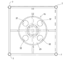
筐体15は、発電機5を取り囲むような円筒状の側壁19と、円状の上壁21と、円状の底壁23とを備えており、フレーム13上に取り付けられている。筐体15の内部には、仕切り板25が備えられ、この仕切り板25により、筐体15の内部の空間が上下の2室に分割されている。すなわち、仕切り板25により、下側の第1室27と、上側の第2室29とに区画されている。下側の第1室27には、発電機5が回転軸を上に向けた状態で設置されている。また、発電機5は、円筒状の側壁19からの距離が略等しくなるように、側壁19が描く円の略中央に取り付けられている。第1室27の側壁19A(本発明の外壁相当)には、筐体15の上下方向の下寄りの位置に、略円形の開口31が8つ略等間隔で形成されている。すなわち、8つの開口31が、発電機5の軸を中心とした円において、略等角度間隔に形成されている。本実施例では、45度間隔である。第1室27の底壁23には、排水用の略円形の開口32が4つ略等間隔で形成されている。すなわち、4つの開口32が、発電機5の軸を中心とした円において、略等角度間隔に形成されている。本実施例では、90度間隔である。開口32から、第1室27に進入した雨水が落下するようにされている。また、開口32から、発電機5の熱も逃がすことができる。
The
第2室29には、カップリング(軸継手)10及びブレーキディスク33(ブレーキロータ)が配置されている。仕切り板25には、発電機5の回転軸よりも、やや大きな貫通孔が形成されており、この貫通孔からは、第1室27に設置された発電機5の回転軸が、第2室29側へ突出している。ブレーキディスク33は、発電機5の回転軸に環装された円盤である。本実施例では、ブレーキディスク33を一対のブレーキパッドで挟み、その摩擦力で回転を制動する空圧のディスクブレーキを用いている。このディスクブレーキが本発明のブレーキ手段に相当する。
In the
第2室29の側壁19Bには、開口は形成されていない。第2室29内には、発電機5は設置されておらず、熱を逃がす必要がないからである。
No opening is formed in the
筐体15の上部には、風車3の回転軸9を回転可能に支持するための軸受35が設けられる。軸受35は、風車3が微弱な風速の風を受けた場合であっても、回転軸9が回転するように十分な定格荷重を有する一方で、回転トルクが小さいものが採用されている。
A bearing 35 for rotatably supporting the
このような構成を有する風力発電装置1は、発電機5を収容する筐体15を備え、筐体15には、発電機5が発する熱を外部へ放出する複数の開口31が設けられているから、以下の作用効果を奏する。すなわち、実施例に係る風力発電装置1は、開口31から発電機5の熱を逃がすことにより、発電機5の発熱による温度上昇を抑制して発電効率の低下を防ぐことができる。しかも、発電機5は、筐体15内に収納されているから、発電機5が自然環境に晒されることによる性能劣化を可能な限り抑制することができる。
The
風力発電装置1は、陸上に設置されるのみならず、洋上にも設置される。また、海に近い地域では一般的に風も強いので、海に近い地域に設置することが効果的である。洋上または洋上付近では、発電機5が潮風により劣化するおそれが高く、特に洋上では、水によりその傾向が顕著である。本実施例の風力発電装置1では、発電効率の低下を抑制しつつ、発電機5が自然環境に晒されることを極力避けることができる。よって、洋上での発電にきわめて有利である。
The
また、発電機5は、円筒状の側壁19の略中央に位置するとともに、側壁19Aには、複数の開口31が略等間隔で形成されているから、発電機5周りの熱を略均等に放射状に外部空間へ逃がすことができる。よって、発電機5の冷却効率が高くなる。
In addition, the
また、開口31は、筐体15の上下方向の下寄りの位置に、形成されており、この位置は、発電機5寄りの位置(発電機5の近傍)であるから、発電機5周りの熱を効果的に外部空間へ逃がすことができる。
In addition, the
本実施例の風力発電装置1では、第1室27の底壁23には、排水用の開口32が設けられている。よって、第1室27内に水が浸入したとしても、この開口32を通じて外へ水を排出できるから、発電機5の性能劣化を極力避けることができる。また、開口32から、発電機5の熱も逃がすことができる。
In the
本実施例の風力発電装置1において、筐体15内には、内部空間を区画する仕切り板25が設けられており、仕切り板25にて第1室27と第2室29に区画されている。そして、発電機5が配置された第1室27を構成する側壁19Aに、開口31が形成されている。この構成では、発電機5の熱を開口31から効率的に逃がすことができる。
In the
また、本実施例の風力発電装置1では、発電機5が配置されていない第2室29の側壁19Bには、開口は形成されていない。この構成では、熱を逃がす必要のないカップリング10やのディスクブレーキは、開口31から隔てることができるから、これらの部材の錆の発生を極力防止することができる。
Moreover, in the
本実施例の風力発電装置1において、筐体15の上には、風車3の回転軸9を回転可能に受ける軸受35が取り付けられている。本実施例のような垂直軸型風力発電装置では、風車3の軸受を発電機5に直接取り付ける場合がある。この場合には、風車3の荷重に耐えうる大きな軸受を発電機5が備えている必要があり、発電機5が大型化する傾向にある。本実施例の構成では、筐体15の上に軸受35が備えられているから、発電機5自体には大きな軸受は不要となる。よって、発電機5を小型化することができる。また、本実施例の風力発電装置1では、軸受35が劣化した場合に、発電機5を取り替えることなく、軸受35のみを交換すれば良いからメンテナンスが容易となり、コストの面でも有利である。
In the
<他の実施例>
本発明は上記記述及び図面によって説明した実施例に限定されるものではなく、例えば次のような実施例も本発明の技術的範囲に含まれる。
<Other embodiments>
The present invention is not limited to the embodiments described with reference to the above description and drawings. For example, the following embodiments are also included in the technical scope of the present invention.
(1)実施例では、ブレード11の数を3つとしたが、ブレード11の数は限定されず、2つでも、4つ以上であってもよい。
(2)実施例では、ブレード11は、回転軸9に直交する面内で同一半径の円周方向に沿って120度の等角度間隔に配置されているものとしたが、ブレード11の数に合わせて、その角度を適宜変更してもよい。例えば、ブレードの数をnとした場合に、角度は360/n度とすることができる。また、実施例では、等角度間隔としたが、必ずしも等角度間隔としなくてもよい。
(3)実施例では、ブレード11は、アルミニウム合金等の軽金属の薄板状の素材から形成されているものとしたが、チタニウム合金等の他の軽金属や、繊維強化プラスチック(FRP)等の複合材を素材として用いてもよい。
(1) In the embodiment, the number of
(2) In the embodiment, the
(3) In the embodiment, the
(4)実施例では、特定の構成の発電機5を例に説明したが、風車3の回転を電力に変換しうる構成であれば公知の様々な発電機を用いることができる。
(5)実施例では、ブレーキ手段として空圧のディスクブレーキを用いた例を示したが、ブレーキ手段としては、これに限られず、回転を止めることができる公知のブレーキを用いることができる。
(6)実施例では、開口31の個数は8つとしたが、個数はこれに限られず、1〜7であっても、9以上であってもよい。
(4) In the embodiment, the
(5) In the embodiment, an example in which a pneumatic disc brake is used as the brake means has been described. However, the brake means is not limited to this, and a known brake capable of stopping rotation can be used.
(6) In the embodiment, the number of the
(7)実施例では、開口31の形状は円状としたが、その形状は特に限定されず、多角形等の様々な形状を採用することができる。
(8)実施例では、開口31は、45度の等角度間隔に配置されているものとしたが、開口31の個数に応じて、その角度を適宜変更してもよい。例えば、開口の個数をn(自然数)とした場合に、角度は360/n度とすることができる。また、実施例では、等角度間隔としたが、必ずしも等角度間隔としなくてもよい。
(9)実施例では、開口32の個数は4つとしたが、個数はこれに限られず、1〜3であっても、5以上であってもよい。
(7) In the embodiment, the shape of the
(8) In the embodiment, the
(9) In the embodiment, the number of the
(10)実施例では、開口32の形状は円状としたが、その形状は特に限定されず、多角形等の様々な形状を採用することができる。
(11)実施例では、開口32は、90度の等角度間隔に配置されているものとしたが、開口32の個数に応じて、その角度を適宜変更してもよい。例えば、開口の個数をn(自然数)とした場合に、角度は360/n度とすることができる。また、実施例では、等角度間隔としたが、必ずしも等角度間隔としなくてもよい。
(12)実施例では、筐体15は、円筒状の側壁19を有するものとしたが、筐体15の形状は特に限定されず、様々な形状を適宜選択できる。
(13)実施例では、支柱7からなる構造体では、支柱7は4本備えられているものとしたが、その本数は必要に応じて適宜選択できる。また、風力発電装置全体を支えるために支柱以外の部材からなる構造体を用いてもよい。
(14)実施例では、ジャイロミル型で説明したが、請求項1〜3の発明では、これに限らず、その他のサボニクス型などの垂直軸型、いわゆるプロペラタイプの水平軸のものでも良い。
(10) In the embodiment, the shape of the
(11) In the embodiment, the
(12) In the embodiment, the
(13) In the embodiment, the structure including the
(14) In the embodiment, the gyromill type has been described. However, the invention of
1…風力発電装置
3…風車
5…発電機
15…筐体
19…側壁
31…開口
32…開口
DESCRIPTION OF
Claims (4)
前記風車の回転軸の回転によって発電する発電機と、
前記発電機を収容する筐体と、を備え、
前記筐体には、前記発電機が発する熱を外部へ放出する開口が設けられていることを特徴とする風力発電装置。 With a windmill,
A generator for generating electricity by rotation of a rotating shaft of the windmill;
A housing for housing the generator,
The casing is provided with an opening for releasing heat generated by the generator to the outside.
前記仕切り板にて区画された複数の空間のうちの前記発電機が配置された空間を構成する外壁に、前記開口が備えられていることを特徴とする請求項1に記載の風力発電装置。 A partition plate for partitioning the internal space is provided in the housing,
2. The wind turbine generator according to claim 1, wherein the opening is provided in an outer wall that constitutes a space in which the generator is arranged among a plurality of spaces partitioned by the partition plate.
前記風車の回転軸を停止させるためのブレーキ手段は、前記複数の空間のうちの前記発電機が配置された空間以外に配されることを特徴とする請求項2に記載の風力発電装置。 A coupling for connecting the rotating shaft of the windmill and the rotating shaft of the generator;
The wind power generator according to claim 2, wherein the brake means for stopping the rotating shaft of the windmill is arranged in a space other than the space in which the generator is disposed among the plurality of spaces.
Priority Applications (1)
| Application Number | Priority Date | Filing Date | Title |
|---|---|---|---|
| JP2016025811A JP2017145698A (en) | 2016-02-15 | 2016-02-15 | Wind power generator |
Applications Claiming Priority (1)
| Application Number | Priority Date | Filing Date | Title |
|---|---|---|---|
| JP2016025811A JP2017145698A (en) | 2016-02-15 | 2016-02-15 | Wind power generator |
Publications (1)
| Publication Number | Publication Date |
|---|---|
| JP2017145698A true JP2017145698A (en) | 2017-08-24 |
Family
ID=59682060
Family Applications (1)
| Application Number | Title | Priority Date | Filing Date |
|---|---|---|---|
| JP2016025811A Pending JP2017145698A (en) | 2016-02-15 | 2016-02-15 | Wind power generator |
Country Status (1)
| Country | Link |
|---|---|
| JP (1) | JP2017145698A (en) |
-
2016
- 2016-02-15 JP JP2016025811A patent/JP2017145698A/en active Pending
Similar Documents
| Publication | Publication Date | Title |
|---|---|---|
| KR101723718B1 (en) | Wind turbine nacelle | |
| CA2870404C (en) | Generator for a gearless wind power installation | |
| ES2952861T3 (en) | Counterweight system for the installation of balanced bushing wind turbine blades | |
| JP5509183B2 (en) | Vertical axis wind turbine bearing and vertical axis wind power generator | |
| JP2011528548A (en) | Power generation system having a plurality of motors / generators | |
| NZ589529A (en) | Brake system, generator and wind turbine | |
| US8198748B1 (en) | Magnetically levitated linear barrel generator | |
| US20120080969A1 (en) | Rotor, generator and wind turbine | |
| GB2463957A (en) | Multiple rotor vertical axis wind turbine | |
| JP2015513628A (en) | Wind turbine rotor | |
| RU2015149805A (en) | WIND TURBINE DESIGN | |
| US9537371B2 (en) | Contra rotor wind turbine system using a hydraulic power transmission device | |
| US20110042960A1 (en) | Bearing device for a wind turbine nacelle | |
| RU2559681C2 (en) | Wind generator with vertical axle and speed-limiting blade | |
| JP7579387B2 (en) | Wind power plant | |
| JP2007107496A (en) | Wind power generation device | |
| WO2017120704A1 (en) | Magnetic levitation device for vertical-axis wind power generator | |
| KR101113594B1 (en) | Generator Vertical Vertical Wind Turbine | |
| JP2017145698A (en) | Wind power generator | |
| EP2409389A1 (en) | A wind turbine and a direct-drive generator | |
| EP2975262B1 (en) | Wind power generation facility | |
| RU2351798C1 (en) | Wind-driver power plant | |
| JP2021099037A (en) | Vertical axis wind power generator | |
| JP6164557B2 (en) | Vertical axis drag type wind turbine capable of preventing over-rotation and wind power generator using the same | |
| RU2565935C1 (en) | Vertical axial wind-driven power plant |