JP2017145706A - Vaporized fuel treatment device - Google Patents
Vaporized fuel treatment device Download PDFInfo
- Publication number
- JP2017145706A JP2017145706A JP2016026074A JP2016026074A JP2017145706A JP 2017145706 A JP2017145706 A JP 2017145706A JP 2016026074 A JP2016026074 A JP 2016026074A JP 2016026074 A JP2016026074 A JP 2016026074A JP 2017145706 A JP2017145706 A JP 2017145706A
- Authority
- JP
- Japan
- Prior art keywords
- fuel
- fuel tank
- pressure
- evaporated
- tank
- Prior art date
- Legal status (The legal status is an assumption and is not a legal conclusion. Google has not performed a legal analysis and makes no representation as to the accuracy of the status listed.)
- Granted
Links
Images




Classifications
-
- F—MECHANICAL ENGINEERING; LIGHTING; HEATING; WEAPONS; BLASTING
- F02—COMBUSTION ENGINES; HOT-GAS OR COMBUSTION-PRODUCT ENGINE PLANTS
- F02M—SUPPLYING COMBUSTION ENGINES IN GENERAL WITH COMBUSTIBLE MIXTURES OR CONSTITUENTS THEREOF
- F02M25/00—Engine-pertinent apparatus for adding non-fuel substances or small quantities of secondary fuel to combustion-air, main fuel or fuel-air mixture
- F02M25/08—Engine-pertinent apparatus for adding non-fuel substances or small quantities of secondary fuel to combustion-air, main fuel or fuel-air mixture adding fuel vapours drawn from engine fuel reservoir
- F02M25/0836—Arrangement of valves controlling the admission of fuel vapour to an engine, e.g. valve being disposed between fuel tank or absorption canister and intake manifold
-
- F—MECHANICAL ENGINEERING; LIGHTING; HEATING; WEAPONS; BLASTING
- F02—COMBUSTION ENGINES; HOT-GAS OR COMBUSTION-PRODUCT ENGINE PLANTS
- F02M—SUPPLYING COMBUSTION ENGINES IN GENERAL WITH COMBUSTIBLE MIXTURES OR CONSTITUENTS THEREOF
- F02M25/00—Engine-pertinent apparatus for adding non-fuel substances or small quantities of secondary fuel to combustion-air, main fuel or fuel-air mixture
- F02M25/08—Engine-pertinent apparatus for adding non-fuel substances or small quantities of secondary fuel to combustion-air, main fuel or fuel-air mixture adding fuel vapours drawn from engine fuel reservoir
-
- B—PERFORMING OPERATIONS; TRANSPORTING
- B01—PHYSICAL OR CHEMICAL PROCESSES OR APPARATUS IN GENERAL
- B01D—SEPARATION
- B01D53/00—Separation of gases or vapours; Recovering vapours of volatile solvents from gases; Chemical or biological purification of waste gases, e.g. engine exhaust gases, smoke, fumes, flue gases, aerosols
- B01D53/02—Separation of gases or vapours; Recovering vapours of volatile solvents from gases; Chemical or biological purification of waste gases, e.g. engine exhaust gases, smoke, fumes, flue gases, aerosols by adsorption, e.g. preparative gas chromatography
- B01D53/04—Separation of gases or vapours; Recovering vapours of volatile solvents from gases; Chemical or biological purification of waste gases, e.g. engine exhaust gases, smoke, fumes, flue gases, aerosols by adsorption, e.g. preparative gas chromatography with stationary adsorbents
- B01D53/0454—Controlling adsorption
-
- B—PERFORMING OPERATIONS; TRANSPORTING
- B60—VEHICLES IN GENERAL
- B60K—ARRANGEMENT OR MOUNTING OF PROPULSION UNITS OR OF TRANSMISSIONS IN VEHICLES; ARRANGEMENT OR MOUNTING OF PLURAL DIVERSE PRIME-MOVERS IN VEHICLES; AUXILIARY DRIVES FOR VEHICLES; INSTRUMENTATION OR DASHBOARDS FOR VEHICLES; ARRANGEMENTS IN CONNECTION WITH COOLING, AIR INTAKE, GAS EXHAUST OR FUEL SUPPLY OF PROPULSION UNITS IN VEHICLES
- B60K15/00—Arrangement in connection with fuel supply of combustion engines or other fuel consuming energy converters, e.g. fuel cells; Mounting or construction of fuel tanks
- B60K15/03—Fuel tanks
- B60K15/035—Fuel tanks characterised by venting means
- B60K15/03504—Fuel tanks characterised by venting means adapted to avoid loss of fuel or fuel vapour, e.g. with vapour recovery systems
-
- B—PERFORMING OPERATIONS; TRANSPORTING
- B60—VEHICLES IN GENERAL
- B60K—ARRANGEMENT OR MOUNTING OF PROPULSION UNITS OR OF TRANSMISSIONS IN VEHICLES; ARRANGEMENT OR MOUNTING OF PLURAL DIVERSE PRIME-MOVERS IN VEHICLES; AUXILIARY DRIVES FOR VEHICLES; INSTRUMENTATION OR DASHBOARDS FOR VEHICLES; ARRANGEMENTS IN CONNECTION WITH COOLING, AIR INTAKE, GAS EXHAUST OR FUEL SUPPLY OF PROPULSION UNITS IN VEHICLES
- B60K15/00—Arrangement in connection with fuel supply of combustion engines or other fuel consuming energy converters, e.g. fuel cells; Mounting or construction of fuel tanks
- B60K15/03—Fuel tanks
- B60K15/035—Fuel tanks characterised by venting means
- B60K15/03519—Valve arrangements in the vent line
-
- F—MECHANICAL ENGINEERING; LIGHTING; HEATING; WEAPONS; BLASTING
- F02—COMBUSTION ENGINES; HOT-GAS OR COMBUSTION-PRODUCT ENGINE PLANTS
- F02D—CONTROLLING COMBUSTION ENGINES
- F02D41/00—Electrical control of supply of combustible mixture or its constituents
- F02D41/0025—Controlling engines characterised by use of non-liquid fuels, pluralities of fuels, or non-fuel substances added to the combustible mixtures
- F02D41/003—Adding fuel vapours, e.g. drawn from engine fuel reservoir
-
- F—MECHANICAL ENGINEERING; LIGHTING; HEATING; WEAPONS; BLASTING
- F02—COMBUSTION ENGINES; HOT-GAS OR COMBUSTION-PRODUCT ENGINE PLANTS
- F02M—SUPPLYING COMBUSTION ENGINES IN GENERAL WITH COMBUSTIBLE MIXTURES OR CONSTITUENTS THEREOF
- F02M25/00—Engine-pertinent apparatus for adding non-fuel substances or small quantities of secondary fuel to combustion-air, main fuel or fuel-air mixture
-
- F—MECHANICAL ENGINEERING; LIGHTING; HEATING; WEAPONS; BLASTING
- F02—COMBUSTION ENGINES; HOT-GAS OR COMBUSTION-PRODUCT ENGINE PLANTS
- F02M—SUPPLYING COMBUSTION ENGINES IN GENERAL WITH COMBUSTIBLE MIXTURES OR CONSTITUENTS THEREOF
- F02M25/00—Engine-pertinent apparatus for adding non-fuel substances or small quantities of secondary fuel to combustion-air, main fuel or fuel-air mixture
- F02M25/08—Engine-pertinent apparatus for adding non-fuel substances or small quantities of secondary fuel to combustion-air, main fuel or fuel-air mixture adding fuel vapours drawn from engine fuel reservoir
- F02M25/0809—Judging failure of purge control system
- F02M25/0818—Judging failure of purge control system having means for pressurising the evaporative emission space
-
- F—MECHANICAL ENGINEERING; LIGHTING; HEATING; WEAPONS; BLASTING
- F02—COMBUSTION ENGINES; HOT-GAS OR COMBUSTION-PRODUCT ENGINE PLANTS
- F02M—SUPPLYING COMBUSTION ENGINES IN GENERAL WITH COMBUSTIBLE MIXTURES OR CONSTITUENTS THEREOF
- F02M25/00—Engine-pertinent apparatus for adding non-fuel substances or small quantities of secondary fuel to combustion-air, main fuel or fuel-air mixture
- F02M25/08—Engine-pertinent apparatus for adding non-fuel substances or small quantities of secondary fuel to combustion-air, main fuel or fuel-air mixture adding fuel vapours drawn from engine fuel reservoir
- F02M25/0854—Details of the absorption canister
-
- F—MECHANICAL ENGINEERING; LIGHTING; HEATING; WEAPONS; BLASTING
- F02—COMBUSTION ENGINES; HOT-GAS OR COMBUSTION-PRODUCT ENGINE PLANTS
- F02M—SUPPLYING COMBUSTION ENGINES IN GENERAL WITH COMBUSTIBLE MIXTURES OR CONSTITUENTS THEREOF
- F02M25/00—Engine-pertinent apparatus for adding non-fuel substances or small quantities of secondary fuel to combustion-air, main fuel or fuel-air mixture
- F02M25/08—Engine-pertinent apparatus for adding non-fuel substances or small quantities of secondary fuel to combustion-air, main fuel or fuel-air mixture adding fuel vapours drawn from engine fuel reservoir
- F02M25/0872—Details of the fuel vapour pipes or conduits
-
- B—PERFORMING OPERATIONS; TRANSPORTING
- B01—PHYSICAL OR CHEMICAL PROCESSES OR APPARATUS IN GENERAL
- B01D—SEPARATION
- B01D2257/00—Components to be removed
- B01D2257/70—Organic compounds not provided for in groups B01D2257/00 - B01D2257/602
- B01D2257/702—Hydrocarbons
- B01D2257/7022—Aliphatic hydrocarbons
-
- B—PERFORMING OPERATIONS; TRANSPORTING
- B01—PHYSICAL OR CHEMICAL PROCESSES OR APPARATUS IN GENERAL
- B01D—SEPARATION
- B01D2259/00—Type of treatment
- B01D2259/45—Gas separation or purification devices adapted for specific applications
- B01D2259/4516—Gas separation or purification devices adapted for specific applications for fuel vapour recovery systems
-
- B—PERFORMING OPERATIONS; TRANSPORTING
- B60—VEHICLES IN GENERAL
- B60K—ARRANGEMENT OR MOUNTING OF PROPULSION UNITS OR OF TRANSMISSIONS IN VEHICLES; ARRANGEMENT OR MOUNTING OF PLURAL DIVERSE PRIME-MOVERS IN VEHICLES; AUXILIARY DRIVES FOR VEHICLES; INSTRUMENTATION OR DASHBOARDS FOR VEHICLES; ARRANGEMENTS IN CONNECTION WITH COOLING, AIR INTAKE, GAS EXHAUST OR FUEL SUPPLY OF PROPULSION UNITS IN VEHICLES
- B60K15/00—Arrangement in connection with fuel supply of combustion engines or other fuel consuming energy converters, e.g. fuel cells; Mounting or construction of fuel tanks
- B60K15/03—Fuel tanks
- B60K15/035—Fuel tanks characterised by venting means
- B60K15/03504—Fuel tanks characterised by venting means adapted to avoid loss of fuel or fuel vapour, e.g. with vapour recovery systems
- B60K2015/03514—Fuel tanks characterised by venting means adapted to avoid loss of fuel or fuel vapour, e.g. with vapour recovery systems with vapor recovery means
-
- B—PERFORMING OPERATIONS; TRANSPORTING
- B60—VEHICLES IN GENERAL
- B60Y—INDEXING SCHEME RELATING TO ASPECTS CROSS-CUTTING VEHICLE TECHNOLOGY
- B60Y2400/00—Special features of vehicle units
- B60Y2400/30—Sensors
- B60Y2400/306—Pressure sensors
Landscapes
- Engineering & Computer Science (AREA)
- Chemical & Material Sciences (AREA)
- Combustion & Propulsion (AREA)
- Mechanical Engineering (AREA)
- General Engineering & Computer Science (AREA)
- Transportation (AREA)
- Life Sciences & Earth Sciences (AREA)
- Sustainable Energy (AREA)
- Sustainable Development (AREA)
- Analytical Chemistry (AREA)
- General Chemical & Material Sciences (AREA)
- Oil, Petroleum & Natural Gas (AREA)
- Chemical Kinetics & Catalysis (AREA)
- Supplying Secondary Fuel Or The Like To Fuel, Air Or Fuel-Air Mixtures (AREA)
Abstract
【課題】蒸発燃料の車外排出を抑制できる蒸発燃料処理装置を提供する。
【解決手段】蒸発燃料処理装置1は、燃料タンク10と、燃料タンク10の外部から内部へガスを供給して燃料タンク10の内圧を上昇させるポンプ4と、ポンプ4の作動を制御する制御装置3と、を備える。制御装置3は、燃料タンク10への給油時以外において、燃料タンク10の内圧が燃料タンク10から蒸発燃料が外部へ流出しない圧力値を下回らないように、ポンプ4を制御する。これによれば、設定された圧力値を下回らないように燃料タンク10の内圧を高く維持することにより、燃料タンク10内の燃料の液面から燃料が蒸発して蒸発燃料が発生することを抑制できる。
【選択図】図1An evaporative fuel processing apparatus capable of suppressing evaporative fuel emission outside a vehicle is provided.
An evaporative fuel processing apparatus (1) includes a fuel tank (10), a pump (4) for supplying gas from the outside to the inside of the fuel tank (10) to increase the internal pressure of the fuel tank (10), and a control device for controlling the operation of the pump (4). 3. The control device 3 controls the pump 4 so that the internal pressure of the fuel tank 10 does not fall below the pressure value at which the evaporated fuel does not flow out from the fuel tank 10 except when the fuel tank 10 is refueled. According to this, by keeping the internal pressure of the fuel tank 10 high so as not to fall below the set pressure value, it is possible to suppress the evaporation of fuel from the fuel level in the fuel tank 10 and the generation of evaporated fuel. it can.
[Selection] Figure 1
Description
この明細書における開示は、自動車における蒸発燃料処理装置に関する。 The disclosure in this specification relates to a fuel vapor processing apparatus in an automobile.
特許文献1に開示される装置では、燃料タンク内の燃料はその液面から蒸発し、蒸発した燃料は燃料タンクの上部空間を満たすため、燃料タンクの内圧が高まることになる。この蒸発燃料は大気に漏洩すると大気汚染の原因になるため、特許文献1の装置は、蒸発燃料をキャニスタで吸着して貯留している。エンジン側の吸気通路に負圧が生じると、キャニスタに貯留した蒸発燃料は吸気とともにエンジンの燃焼室に供給され、燃焼室で燃焼することで処理し、大気への放出を抑制している。 In the apparatus disclosed in Patent Document 1, the fuel in the fuel tank evaporates from the liquid surface, and the evaporated fuel fills the upper space of the fuel tank, so that the internal pressure of the fuel tank increases. When this evaporated fuel leaks into the atmosphere, it causes air pollution. Therefore, the apparatus of Patent Document 1 adsorbs and stores the evaporated fuel with a canister. When negative pressure is generated in the intake passage on the engine side, the evaporated fuel stored in the canister is supplied to the combustion chamber of the engine together with the intake air, and is processed by burning in the combustion chamber, thereby suppressing release to the atmosphere.
近年、ガソリンエンジンの技術向上によってエンジン損失が低減し、エンジン負圧が減少している。また、ハイブリッド自動車等は、走行中にエンジンを停止し、他のエネルギを使用して走行する。このようにエンジン負圧の減少や走行中のエンジン停止によって、発生した蒸発燃料を十分に処理できずに、蒸発燃料が大気に漏洩するという懸念がある。また、近年のガソリンエンジンは省燃費化が進み、燃焼行程でのガソリン使用量が減っているため、蒸発燃料を処理できる量が減ってきている。 In recent years, engine loss has been reduced due to technological improvements in gasoline engines, and engine negative pressure has decreased. In addition, a hybrid vehicle or the like travels using other energy by stopping the engine while traveling. As described above, there is a concern that the evaporated fuel is leaked to the atmosphere because the generated evaporated fuel cannot be sufficiently processed due to the decrease of the engine negative pressure or the stop of the engine during traveling. In recent years, fuel consumption has been reduced in gasoline engines, and the amount of gasoline used in the combustion stroke has been reduced.
このような課題に鑑み、この明細書における開示の目的は、蒸発燃料の車外排出を抑制できる蒸発燃料処理装置を提供することである。 In view of such a problem, an object of the disclosure in this specification is to provide an evaporative fuel processing apparatus capable of suppressing evaporative fuel emission outside the vehicle.
この明細書に開示された複数の態様は、それぞれの目的を達成するために、互いに異なる技術的手段を採用する。また、特許請求の範囲およびこの項に記載した括弧内の符号は、ひとつの態様として後述する実施形態に記載の具体的手段との対応関係を示す一例であって、技術的範囲を限定するものではない。 A plurality of aspects disclosed in this specification adopt different technical means to achieve each purpose. In addition, the reference numerals in the parentheses described in the claims and in this section are examples showing the correspondence with the specific means described in the embodiments described later as one aspect, and limit the technical scope. is not.
開示された蒸発燃料処理装置のひとつは、内燃機関(2)の燃料を貯留する燃料タンク(10)と、燃料タンクの外部から内部へガスを供給して燃料タンクの内圧を上昇させる加圧処理を行う加圧部(4;14)と、加圧部の作動を制御する制御装置(3)と、を備え、制御装置は、燃料タンクへの給油時以外において、燃料タンクの内圧が、燃料タンクから蒸発燃料が大気へ流出しない圧力値を下回らないように、加圧部を制御して加圧処理を行う蒸発燃料処理装置である。 One of the disclosed evaporative fuel processing apparatuses includes a fuel tank (10) for storing fuel of an internal combustion engine (2), and a pressurizing process for increasing the internal pressure of the fuel tank by supplying gas from the outside to the inside of the fuel tank. And a control device (3) for controlling the operation of the pressurization unit. The control device is configured so that the internal pressure of the fuel tank is the fuel other than during fueling to the fuel tank. This is an evaporative fuel processing device that controls the pressurizing unit to perform a pressurizing process so that the evaporative fuel does not flow out from the tank to the atmosphere.
この蒸発燃料処理装置は、燃料タンクへの給油時を除く場合に、加圧部によるガス供給によって燃料タンクの内圧を、燃料タンクから蒸発燃料が大気へ流出しない圧力値以上に維持する。燃料タンクから蒸発燃料が大気へ流出しない圧力値は、装置によって個別に設定される値である。このように設定された圧力値を下回らないように燃料タンクの内圧を高く維持することにより、燃料タンク内の燃料の液面から燃料が蒸発して蒸発燃料が発生することを抑制できるとともに、大気等に燃料が漏洩してしまう事態を抑止できる。したがって、この蒸発燃料処理装置によれば、蒸発燃料の車外排出を抑制できる。 In the evaporative fuel processing device, when the fuel tank is not refueled, the internal pressure of the fuel tank is maintained at a pressure value at which evaporative fuel does not flow out from the fuel tank to the atmosphere by supplying gas from the pressurizing unit. The pressure value at which the evaporated fuel does not flow out from the fuel tank to the atmosphere is a value set individually by the apparatus. By keeping the internal pressure of the fuel tank high so that it does not fall below the pressure value set in this way, it is possible to suppress the evaporation of fuel from the fuel level in the fuel tank and the generation of evaporated fuel. It is possible to suppress the situation where fuel leaks. Therefore, according to this evaporated fuel processing apparatus, the discharge of evaporated fuel from the vehicle can be suppressed.
以下に、図面を参照しながら本開示を実施するための複数の形態を説明する。各形態において先行する形態で説明した事項に対応する部分には同一の参照符号を付して重複する説明を省略する場合がある。各形態において構成の一部のみを説明している場合は、構成の他の部分については先行して説明した他の形態を適用することができる。各実施形態で具体的に組み合わせが可能であることを明示している部分同士の組み合わせばかりではなく、特に組み合わせに支障が生じなければ、明示していなくても実施形態同士を部分的に組み合せることも可能である。 Hereinafter, a plurality of modes for carrying out the present disclosure will be described with reference to the drawings. In each embodiment, parts corresponding to the matters described in the preceding embodiment may be denoted by the same reference numerals, and redundant description may be omitted. When only a part of the configuration is described in each mode, the other modes described above can be applied to the other parts of the configuration. Not only combinations of parts that clearly indicate that the combination is possible in each embodiment, but also a combination of the embodiments even if they are not clearly specified unless there is a problem with the combination. It is also possible.
(第1実施形態)
第1実施形態に係る蒸発燃料処理装置1について、図1〜図4を参照しながら説明する。蒸発燃料処理装置1は、燃料タンク10内の燃料が蒸発した燃料蒸気の発生を抑制できる機能を有し、燃料タンク10からの蒸発燃料が大気に放出されることを防止できる装置である。
(First embodiment)
The evaporated fuel processing apparatus 1 according to the first embodiment will be described with reference to FIGS. The evaporative fuel processing device 1 has a function capable of suppressing the generation of fuel vapor in which the fuel in the
蒸発燃料処理装置1は、以下、装置1と称することもある。蒸発燃料処理装置1は、内燃機関2で燃焼されるガソリン等の燃料を貯留する燃料タンク10を備える。燃料タンク10内の燃料は、燃料タンク10と内燃機関2とをつなぐ燃料供給通路を介してインジェクタ等から内燃機関2に供給され、吸気と混合されて内燃機関2の燃焼室で燃焼する。内燃機関2には、燃焼室に吸入される空気が流れる吸気管21と外部に排出される排気ガスが流れる排気管23とが接続されている。吸気管21には、内燃機関2側が複数の部位に分岐する吸気マニホールド20が接続されており、それぞれの部位には燃焼室が接続されている。排気管23には、複数の部位に分岐する排気マニホールド22が接続されている。
Hereinafter, the evaporative fuel processing apparatus 1 may be referred to as the apparatus 1. The evaporative fuel processing apparatus 1 includes a
燃料タンク10は、通路40を形成する配管によってポンプ4に接続されている。燃料タンク10にはタンク内の圧力を検出する圧力センサ11が設けられている。燃料タンク10には給油口を開閉する給油部111が設けられている。燃料タンク10に給油する際は給油部111を開状態して給油が行われ、給油が終了すると給油部111が閉状態になり燃料タンク10の内部と大気とは遮断される。
The
燃料タンク10には、通路40と燃料タンク10の内部との連通を許容可能および禁止可能とするために、通路を開閉する開閉弁110が一体に設けられている。開閉弁110は、通路を開放する開状態に制御されたときに、ポンプ4と燃料タンク10の内部とを連通させる。開閉弁110は、通路を閉鎖する閉状態に制御されたときに、燃料タンク10の内部を密閉空間にすることができる密閉弁として機能する。ポンプ4は、モータ等のアクチュエータによって回転するタービンを備える流体駆動装置であり、大気を通路40を介して燃料タンク10に向けて送る。ポンプ4は、開閉弁110が開状態であるときに外部から通路40に空気を吸入するように制御されることで、空気を燃料タンク10の内部に供給して燃料タンク10の内圧を高める加圧部を構成する。
The
制御装置3は、蒸発燃料処理装置1の電子制御ユニットである。制御装置3は、少なくともひとつの演算処理装置(CPU)と、プログラムとデータとを記憶する記憶媒体としての少なくともひとつのメモリ装置とを有する。制御装置3は、例えばコンピュータによって読み取り可能な記憶媒体を備えるマイクロコンピュータによって提供される。記憶媒体は、コンピュータによって読み取り可能なプログラムを非一時的に格納する非遷移的実体的記憶媒体である。記憶媒体は、半導体メモリまたは磁気ディスクなどによって提供されうる。制御装置3は、ひとつのコンピュータ、またはデータ通信装置によってリンクされた一組のコンピュータ資源によって提供されうる。プログラムは、制御装置3によって実行されることによって、制御装置3をこの明細書に記載される装置として機能させ、この明細書に記載される方法を実行するように制御装置3を機能させる。
The
制御装置3が提供する手段および/または機能は、実体的なメモリ装置に記録されたソフトウェアおよびそれを実行するコンピュータ、ソフトウェアのみ、ハードウェアのみ、あるいはそれらの組合せによって提供することができる。例えば、制御装置3がハードウェアである電子回路によって提供される場合、それは多数の論理回路を含むデジタル回路、またはアナログ回路によって提供することができる。
The means and / or function provided by the
制御装置3は、蒸発燃料処理装置1における基本制御を行う他、判定回路を構成する判定部30によって、ポンプ4による燃料タンク10内の加圧処理の要否を判定する。このため、制御装置3は、ポンプ4、開閉弁110のそれぞれのアクチュエータに接続され、これらの作動を制御する。
The
制御装置3は、内燃機関2の運転、停止に関係なく、モータを駆動してポンプ4の運転、停止を制御することができる。制御装置3は、内燃機関2の運転、停止に関係なく、開閉弁110の弁位置を制御することができる。制御装置3の入力ポートには、少なくとも、圧力センサ11による燃料タンク10の内部圧力に対応する信号が入力される。制御装置3は、燃料タンク10の内部圧力に対応する内圧検出値に応じてポンプ4の運転状態、開閉弁110の開閉状態を制御して、燃料タンク10内から蒸発燃料が外部に流出しないように蒸発燃料抑制制御を実行する。
The
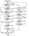
図2のフローチャート、図3および図4のチャートを参照して、蒸発燃料抑制制御を説明する。制御装置3は、図2のフローチャートにしたがった処理を実行する。制御装置3における判定部30は、図2のステップ100、130、110、113、160、190の各判定処理を実行する。本フローチャートは、車両の内燃機関2が運転している走行時、停止している駐車時にかかわらず作動する。蒸発燃料抑制制御は、内燃機関2の運転、停止にかかわらず継続的に実行することができる。また、本フローチャートの途中のステップを実行しているときに、給油部111の給油コックが開いたことを示す信号が制御装置3に入力されると、強制的にステップ120に飛ぶように構成されている。
The evaporated fuel suppression control will be described with reference to the flowchart of FIG. 2 and the charts of FIGS. 3 and 4. The
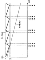
本フローチャートが開始されると、制御装置3は、ステップ100で給油コックを開いたことを示す信号が入力されたか否かを判定する。使用者が給油コックを開けると、制御装置3にその状態を知らせる信号が入力されるため、制御装置3は、これから給油が行われることを認識し、ステップ120で開閉弁110を開状態に制御する。開閉弁110が開くことで燃料タンク10内の蒸発燃料は通路40側に流出し、燃料タンク10の内圧が急激に低下し始める。そして、図3に図示するように、燃料タンク10の内圧が十分に低下してから、給油が開始される。
When this flowchart is started, the
ポンプ4が停止状態であるときに通路40を閉塞する機構を有する場合は、通路40側に流出した蒸発燃料は、ポンプ4でせき止められるため、ポンプ4を通過して大気に流出しない。つまり、蒸発燃料は、燃料タンク10の内部とポンプ4との間の範囲で通路40にとどまるようになる。
When the pump 4 has a mechanism for closing the
次のステップ130では、給油コックが閉まったことを示す信号が入力されたか否かを判定する。ステップ130の判定処理は、制御装置3に給油コックが閉まったことを示す信号が入力されるまで繰り返される。使用者が給油コックを閉めると、制御装置3にその状態を知らせる信号が入力されるため、制御装置3は給油が終了したことを認識できる。
In the next step 130, it is determined whether or not a signal indicating that the refueling cock is closed is input. The determination process in step 130 is repeated until a signal indicating that the refueling cock is closed is input to the
ステップ130で、給油が終了したことを示す信号の入力があったと判定すると、ステップ140でポンプ4を運転し、ステップ150で開状態に維持するように開閉弁110を制御する。これらの処理により、ポンプ4が外部から吸い込んだ空気が通路40を介して燃料タンク10の内部に供給され、燃料タンク10の内圧は上昇し始める。タンクへの加圧処理は、ステップ160で燃料タンク10の内圧が第1閾値P1以上になったと判定されるまで継続する。第1閾値P1は、燃料タンク10内の液面より上の内部空間が燃料蒸気で満たされたときに測定される圧力である飽和状態圧力と同じまたはそれ以上の圧力に設定されている。第1閾値P1は、飽和状態圧力以上の圧力であって、装置1と同様の実機において測定された実測値に基づいて予め三段階に設定された所定圧力のうち、最も高く設定された圧力である。
If it is determined in step 130 that a signal indicating that refueling has been completed is input, the pump 4 is operated in step 140, and the on-off
ステップ160で燃料タンク10の内圧が第1閾値P1以上になったと判定すると、制御装置3は、ステップ170で閉状態に開閉弁110を制御し、ステップ180でポンプ4の運転を停止する。第1閾値P1以上になったタンクの内圧は、加圧処理の停止、燃料消費量の増加等に伴い、図4に示すように徐々に低下していく。そして、加圧処理の停止状態においてステップ190では、燃料タンク10の内圧が第2閾値P2以下であるか否かを判定する。第2閾値P2は、第1閾値P1よりも所定圧力分低く設定した、飽和状態圧力以上の値であり、前述のように予め三段階に設定された所定圧力のうち、二番目に低く設定された圧力である。
If it is determined in step 160 that the internal pressure of the
タンクへの加圧を行わない状態は、ステップ190で燃料タンク10の内圧が第2閾値P2を超えていると判定している間は継続する。ステップ190で燃料タンク10の内圧が第2閾値P2以下であると判定すると、ステップ140に進み、再びタンクに対して加圧を行う。これにより、図4に図示するように、第2閾値P2以下まで低下した内圧は、上昇し、この加圧処理はステップ160で燃料タンク10の内圧が第1閾値P1以上になったと判定されるまで継続する。
The state in which no pressure is applied to the tank continues while it is determined in step 190 that the internal pressure of the
このような給油行為後の処理を継続することにより、図3および図4に示すように、燃料タンク10の内圧は、低下と上昇を繰り返しながらも、前述の飽和状態圧力以上の圧力に設定した第3閾値P3よりも高い圧力値に維持される。第3閾値P3は、第2閾値P2よりも所定圧力分低く設定した、飽和状態圧力以上の値であり、前述のように予め三段階に設定された所定圧力のうち、最も低く設定された圧力である。第3閾値P3は、燃料タンク10から蒸発燃料が大気へ流出しない圧力値でもある。
By continuing such processing after the refueling action, as shown in FIGS. 3 and 4, the internal pressure of the
前述のステップ100で給油コックを開いたことを示す信号が入力されていないと判定すると、制御装置3は、給油時以外の状態、例えば、走行状態、停止状態、駐車状態であると認識する。次にステップ110で燃料タンク10の内圧が第2閾値P2以下であるか否かを判定する。内圧が第2閾値P2を超えている場合は、内圧が高い状態に維持されていて、燃料タンク10内の蒸発燃料が外部に流出しない状態であるため、この状態を維持できている間は、ステップ100に進み、次の給油が開始されるか否かの判定を実行する。
If it is determined that the signal indicating that the refueling cock has been opened is not input in Step 100 described above, the
ステップ110で燃料タンク10の内圧が第2閾値P2以下になったと判定すると、ステップ111でポンプ4を運転し、ステップ112で開状態に維持するように開閉弁110を制御する。これにより、ポンプ4が外部から吸い込んだ空気を通路40を介して燃料タンク10の内部に供給して燃料タンク10の内圧を上げる。このタンクへの加圧処理は、ステップ113で燃料タンク10の内圧が第1閾値P1以上になったと判定されるまで継続する。
If it is determined in
ステップ113で燃料タンク10の内圧が第1閾値P1以上になったと判定すると、ステップ114で閉状態に開閉弁110を制御し、ステップ115でポンプ4の運転を停止する。これにより、タンクの内圧は、第1閾値P1以上の状態から、加圧処理の停止、燃料消費量の増加等に伴い、図4に示すように徐々に低下していく。そしてステップ190に進み、加圧処理の停止状態で燃料タンク10の内圧が第2閾値P2以下になれば、ステップ140に進み、再びタンクへの加圧処理を開始する。図4に図示するように、給油時以外では、タンクの内圧は下降と上昇とを繰り返しながら、燃料タンク10から蒸発燃料が大気へ流出しない第3閾値P3以上に維持される。第3閾値P3以上の圧力は、燃料タンク10の内部においてベーパ発生の抑制が期待できる圧力値である。したがって、蒸発燃料処理装置1は、継続的に蒸発燃料の車外排出を抑制することができる。
If it is determined in step 113 that the internal pressure of the
また、圧力センサ11は、燃料タンク10の内部からポンプ4等の加圧部に至るまでの通路に含まれる所定箇所の圧力を検出する装置の一例である。したがって、ステップ110、113、160、190での判定処理に用いる圧力は、タンクの内圧が含まれる所定箇所の圧力であり、通路40に設けられた圧力センサによって検出するように構成してもよい。
The
次に、第1実施形態の蒸発燃料処理装置1がもたらす作用効果について説明する。装置1は、燃料タンク10と、燃料タンク10の外部から内部へガスを供給して燃料タンク10の内圧を上昇させるポンプ4と、ポンプ4の作動を制御する制御装置3と、を備える。制御装置3は、燃料タンク10への給油時以外において、燃料タンク10の内圧が、燃料タンク10から蒸発燃料が外部へ流出しない圧力値を下回らないように、ポンプ4を制御する。
Next, the effect which the evaporative fuel processing apparatus 1 of 1st Embodiment brings is demonstrated. The apparatus 1 includes a
この装置1によれば、燃料タンク10への給油時を除くときに、ポンプ4によるガス供給によって燃料タンク10の内圧を、燃料タンク10から蒸発燃料が外部へ流出しない圧力値以上に維持するように制御する。この圧力値は、制御対象とする装置によって個別に設定することが求められる値である。すなわち、この圧力値は、実機による実験や、蒸発燃料が外部へ流出しないことを確認できた実測値に基づいて、設定される値である。装置1は、このように設定された所定の圧力値を下回らないように燃料タンク10の内圧を高く維持することにより、燃料タンク10内の燃料の液面から燃料が蒸発して蒸発燃料が発生することを抑制できる。したがって、この装置1によれば、蒸発燃料が車外や大気等に漏洩してしまう事態を抑止できる。
According to this apparatus 1, when the
前述の蒸発燃料抑制制御によれば、制御装置3は、燃料タンク10の内圧または燃料タンク10の内部からポンプ4に至る通路に含まれる部位の圧力が、第3閾値P3よりも高く設定された第1閾値P1以上になると加圧処理を停止するようにポンプ4を制御する。また、制御装置3は、燃料タンク10の内圧または燃料タンク10の内部からポンプ4に至る通路に含まれる部位の圧力が、第3閾値P3よりも高く第1閾値P1よりも低く設定された第2閾値P2以下になると加圧処理を開始するようにポンプ4を制御する。
According to the fuel vapor suppression control described above, the
この制御によれば、燃料タンク10の内圧または燃料タンク10の内部からポンプ4に至る通路に含まれる部位の圧力を、二つの閾値を大きく下回ったり上回ったりしない圧力に制御することができる。したがって、蒸発燃料が大気へ流出しない圧力値である第3閾値P3以上に維持する制御をより確実に実施することができる。また、検出部位の圧力が第1閾値P1以上になった場合には加圧処理を停止するので、加圧のためのポンプ4の稼働時間を抑制する制御を実施できる。さらに、検出部位の圧力が第1閾値P1を大きく上回って高くなりすぎるような事態を防止できるので、高圧負荷時間を短くできる。したがって、燃料タンク10や通路を構成する配管にかかる負荷を抑制することができる。
According to this control, the internal pressure of the
(第2実施形態)
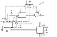
第2実施形態の蒸発燃料処理装置101について、図5および図6を参照して説明する。以下、蒸発燃料処理装置101は装置101とも称する。装置101は、第1実施形態の装置1に対して、燃料タンク10から発生した蒸発燃料を吸着可能なキャニスタ13を備える点が相違する。したがって、装置101では、タンク内の蒸発燃料は開状態である開閉弁110を通過して通路40に流出し、キャニスタ13に流入して吸着される。装置101は、キャニスタ13に吸着された蒸発燃料を燃料タンク10の内部に戻す機能を有している。第2実施形態で特に説明しない構成、作用、効果については、第1実施形態と同様であり、以下、第1実施形態と異なる点についてのみ説明する。
(Second Embodiment)
A fuel
燃料タンク10は、通路40を形成する配管によってキャニスタ13の流入部に接続されている。キャニスタ13は、内部に活性炭等の吸着材が封入された容器であり、燃料タンク10内で発生する蒸発燃料を、通路40を介して取り入れ、吸着材に一時的に吸着する。キャニスタ13は、配管で形成される通路50を介して燃料タンク10の内部と連通している。
The
通路を形成する配管には、通路50を開く開状態と通路50を閉塞する閉状態とに切り換えるバルブ5が設けられている。通路50は、燃料タンク10内の底部に設置された流出部51に接続されている。したがって、流出部51は燃料タンク10内に貯留された燃料に浸かった状態である。流出部51には複数の小孔部が形成されている。バルブ5を開状態に制御し燃料タンク10に向けてガスを供給するようにポンプ4を制御すると、キャニスタ13に吸着されていた蒸発燃料は通路50を燃料タンク10へ向けて流れ、燃料タンク10内の燃料に対して複数の小孔部から泡状になって噴出される。これにより、蒸発燃料は燃料に溶解しやすい状態で燃料タンク10の内部に戻される。この明細書ではこのように蒸発燃料が泡状でタンク内に戻されることを蒸発燃料のバブリングという。
A pipe that forms the passage is provided with a
給油コックが開くと、制御装置3は、その信号を取得し、開閉弁110を開状態に制御する。開閉弁110が開くと、燃料タンク10内の蒸発燃料は通路40を介してキャニスタ13に一気に流入するため、図6に長破線で示すように、キャニスタ13内のベーパ量が急激に上昇する。そして、給油開始後、給油終了までの間に燃料タンク10内の燃料は増加するので、蒸発燃料は通路40を介してキャニスタ13に流入し続ける。このため、キャニスタ13内のベーパ量は、開閉弁110を開いた直後よりも小さい増加率で増加し続ける。
When the fueling cock is opened, the
給油が終了して給油コックが閉められると、バルブ5を開状態に制御しポンプ4による加圧を開始するので、通路40を通じてガスがタンク内に供給されるとともに、キャニスタ13に吸着された蒸発燃料が通路50を介して流出部51に供給される。この作動により、図6に長破線で示すように開閉弁110が閉状態に制御されるまで、タンクの内圧は上昇し続け、同時にキャニスタ13内のベーパ量は減少し続ける。
When refueling is completed and the refueling cock is closed, the
このように装置101は、制御装置3が加圧処理を行う際に、ポンプ4がガスを供給するときの加圧力を利用して、キャニスタ13から脱離させた蒸発燃料を燃料タンク10の燃料に対して流出部51から噴出させる。この装置101によれば、ポンプ4による燃料タンク10への加圧処理により、タンク外部への蒸発燃料の流出を防ぐとともに、キャニスタ13に吸着された蒸発燃料を燃料タンク10に返還することができる。
As described above, when the
(第3実施形態)
第3実施形態に係る蒸発燃料処理装置201について、図7を参照しながら説明する。以下、蒸発燃料処理装置201は装置201とも称する。装置201は、キャニスタ13に吸着した燃料中のHCガス等を内燃機関2の吸気通路に供給する点が第1実施形態とは相違する。装置201では、第1実施形態の蒸発燃料抑制制御においてポンプ4による加圧処理はパージポンプ14によって実施される。したがって、パージポンプ14は、ガスを燃料タンク10の内部に供給して燃料タンク10の内圧を高める加圧部を構成する。装置201は、図7に示すように、内燃機関2の吸気通路を構成する内燃機関2の吸気系と、蒸発燃料を内燃機関2の吸気系に供給する蒸発燃料パージ系と、を備えて構成される。第3実施形態で特に説明しない構成、作用、効果については、第1実施形態と同様であり、以下、第1実施形態と異なる点についてのみ説明する。
(Third embodiment)
An evaporated
内燃機関2の吸気通路に導入された蒸発燃料は、インジェクタ等から内燃機関2に供給される燃焼用燃料と混合されて、内燃機関2の燃焼室で燃焼される。内燃機関2は少なくともキャニスタ13から脱離された蒸発燃料と燃焼用燃料とを混合して燃焼する。内燃機関2の吸気系は、吸気マニホールド20に吸気管21が接続され、さらに吸気管21の途中にスロットルバルブ25、エアフィルタ24等が設けられて構成されている。内燃機関2の吸気通路は、吸気マニホールド20、吸気管21、スロットルバルブ25、エアフィルタ24等を含んで構成される通路である。
The evaporated fuel introduced into the intake passage of the
蒸発燃料パージ系は、燃料タンク10とキャニスタ13がベーパ通路16を構成する配管で接続され、キャニスタ13と吸気管21がパージ通路17を構成する配管とパージバルブ15とを介して接続されている。パージ通路17の途中には、パージポンプ14が設けられている。パージ通路17には、パージポンプ14の内部通路とパージバルブ15の内部通路とが含まれる。吸気管21は、内燃機関2の吸気通路を形成する通路形成部材である。
In the evaporative fuel purge system, the
エアフィルタ24は、吸気管21の上流部に設けられ、吸気中の塵や埃等を捕捉する。スロットルバルブ25は、吸気マニホールド20の入口部における開度を調節して、吸気マニホールド20内に流入する吸気量を調節する吸気量調節弁である。吸気は、吸気通路をエアフィルタ24、スロットルバルブ25の順に通過して吸気マニホールド20内に流入し、インジェクタ等から噴射される燃焼用燃料と所定の空燃比となるように混合されて燃焼室で燃焼される。
The
燃料タンク10は、ベーパ通路16を形成する配管によってキャニスタ13の流入部に接続されている。キャニスタ13は、内部に活性炭等の吸着材が封入された容器であり、燃料タンク10内で発生する蒸発燃料を、ベーパ通路16を介して取り入れ、吸着材に一時的に吸着する。キャニスタ13には、バルブモジュール12が一体に設けられている。バルブモジュール12は、外部の新鮮な空気を吸入するための吸入部を開閉するキャニスタクローズバルブと、大気に対してガスを放出したり、大気を吸入したりすることが可能な内部ポンプと、が内蔵されている。キャニスタクローズバルブは、CCVとも称する。キャニスタ13がCCVを備えることにより、キャニスタ13内に大気圧を作用させることができる。キャニスタ13は、吸入された新鮮な空気によって吸着材に吸着した蒸発燃料を容易に脱離可能、すなわちパージすることができる。
The
キャニスタ13には、吸着材から脱離された蒸発燃料が流出される流出部にパージ通路17の一部を形成する配管の一端が接続されている。この配管の他端はパージポンプ14の流入部に接続されている。さらに、パージポンプ14とパージバルブ15は、パージ通路17の一部を形成する配管によって接続されている。パージポンプ14は、モータ等のアクチュエータによって回転するタービンを備えるパージ用の流体駆動装置であり、キャニスタ13からの蒸発燃料を内燃機関2の吸気通路に向けて送る。
One end of a pipe that forms a part of the
パージバルブ15は、パージ通路17を開閉する弁体を有する開閉装置の一例である。パージバルブ15は、弁体によって本体の内部に設けられた燃料供給用通路を開閉することで、キャニスタ13からの蒸発燃料を内燃機関2へ供給することを許可する許可状態と阻止する阻止状態とを実現できる。パージバルブ15は、弁体、電磁コイルおよびスプリングを備えた電磁弁装置によって構成される。パージバルブ15は、制御装置3によって通電状態、非通電状態に切り替えられることで、燃料供給用通路の全開状態から全閉状態にわたって開度が制御される。パージバルブ15は、電磁コイルを有する電気回路に通電されたときに発生する電磁力とスプリングの付勢力との差に応じて弁体を移動させ、本体に形成される弁座から弁体を離間して燃料供給用通路を開放する。制御装置3は、通電のオン時間とオフ時間とによって形成される1周期の時間に対するオン時間の比率、すなわちデューティ比を制御して電磁コイルに通電を行う。パージバルブ15は、デューティコントロールバルブともいう。このようなパージバルブ15に対する通電制御により、燃料供給用通路を流通する蒸発燃料の流量を調節することができる。
The
制御装置3は、パージポンプ14、パージバルブ15、開閉弁110、CCV、内部ポンプのそれぞれのアクチュエータに接続され、これらの作動を制御する。制御装置3は、パージポンプ14のモータ等のアクチュエータに接続され、内燃機関2の運転、停止に関係なく、モータを駆動してパージポンプ14の運転、停止を制御することができる。
The
キャニスタ13から、吸気マニホールド20内に吸引された蒸発燃料は、インジェクタ等から内燃機関2に供給される本来の燃焼用燃料と混合されて、内燃機関2の燃焼室で燃焼される。内燃機関2の燃焼室においては、燃焼用燃料と吸気との混合割合である空燃比が予め定めた所定の空燃比となるように制御される。制御装置3は、パージバルブ15の開閉時間をデューティ制御することにより、蒸発燃料をパージしても所定の空燃比が維持されるように蒸発燃料のパージ量を調節する。
The evaporated fuel sucked into the
前述したように、パージポンプ14は、第1実施形態に記載したポンプ4と同様の動作も行うことができ、蒸発燃料発生を抑制するための加圧作用、効果については前述の実施形態を援用することができる。したがって、第1実施形態で図2および図3を参照しながら説明した蒸発燃料抑制制御においてポンプ4はパージポンプ14に置き換えることで装置201でも同様の制御を実施することができる。また、パージポンプ14が燃料タンク10に対してガスを供給してタンクの内圧を上昇させる加圧処理を行うときは、第2実施形態において図6を参照して説明したように、タンクの内圧は上昇し続け、同時にキャニスタ13内のベーパ量は減少し続ける。
As described above, the
これにより、制御装置3は、燃料タンク10への給油時以外において、燃料タンク10の内圧が、燃料タンク10から蒸発燃料が大気へ流出しない圧力値を下回らないように、パージポンプ14を制御して加圧処理を行う。この装置201によれば、燃料タンク10への給油時を除くときに、パージポンプ14によるガス供給によって燃料タンク10の内圧を、燃料タンク10から蒸発燃料が外部へ流出しない圧力値以上に維持するように制御する。装置201は、蒸発燃料をパージするためのパージポンプ14を加圧部としても機能させることで、所定の圧力値を下回らないように燃料タンク10の内圧を高く維持し、燃料タンク10内の燃料の液面から燃料が蒸発して蒸発燃料が発生することを抑制できる。したがって、この装置201によれば、蒸発燃料が車外や大気等に漏洩してしまう事態を抑止できる。
Thereby, the
(他の実施形態)
この明細書の開示は、例示された実施形態に制限されない。開示は、例示された実施形態と、それらに基づく当業者による変形態様を包含する。例えば、開示は、実施形態において示された部品、要素の組み合わせに限定されず、種々変形して実施することが可能である。開示は、多様な組み合わせによって実施可能である。開示は、実施形態に追加可能な追加的な部分をもつことができる。開示は、実施形態の部品、要素が省略されたものを包含する。開示は、ひとつの実施形態と他の実施形態との間における部品、要素の置き換え、または組み合わせを包含する。開示される技術的範囲は、実施形態の記載に限定されない。開示される技術的範囲は、特許請求の範囲の記載によって示され、さらに特許請求の範囲の記載と均等の意味および範囲内での全ての変更を含むものと解されるべきである。
(Other embodiments)
The disclosure of this specification is not limited to the illustrated embodiments. The disclosure encompasses the illustrated embodiments and variations by those skilled in the art based thereon. For example, the disclosure is not limited to the combination of components and elements shown in the embodiments, and various modifications can be made. The disclosure can be implemented in various combinations. The disclosure may have additional parts that can be added to the embodiments. The disclosure includes those in which the components and elements of the embodiment are omitted. The disclosure encompasses parts, element replacements, or combinations between one embodiment and another. The technical scope disclosed is not limited to the description of the embodiments. The technical scope disclosed is indicated by the description of the scope of claims, and should be understood to include all modifications within the meaning and scope equivalent to the description of the scope of claims.
前述の実施形態に記載のポンプ4は、通路40に設けられるものに限定されない。ポンプ4は、タンク内部を加圧可能なように燃料タンク10に一体に装着される形態でもよい。この場合のポンプ4は、開閉弁110と一体に構成することもできる。
The pump 4 described in the above embodiment is not limited to the one provided in the
前述の実施形態に記載の開閉弁110は、タンク外部からタンク内部への流体の流入を許容し、タンク内部からタンク外部への流体の流出を阻止するように動作する逆流防止弁に置き換えてもよい。
The on-off
第2実施形態において、ポンプ4を制御することによって燃料タンク10内にガスを供給してタンク内部を加圧するように構成しているが、キャニスタ13に一体のバルブモジュール12の内部ポンプを制御してタンク内部を加圧するようにしてもよい。
In the second embodiment, the pump 4 is controlled to supply gas into the
第3実施形態において、パージポンプ14を制御することによって燃料タンク10内にガスを供給してタンク内部を加圧するように構成しているが、キャニスタ13に一体のバルブモジュール12の内部ポンプを制御してタンク内部を加圧するようにしてもよい。
In the third embodiment, the
第3実施形態のように蒸発燃料を内燃機関2の吸気通路に供給可能な蒸発燃料処理装置においては、開閉弁110と前述の逆流防止弁の両方を備えるように構成してもよい。
The evaporative fuel processing apparatus capable of supplying evaporative fuel to the intake passage of the
第3実施形態では、吸気管21に装着する弁装置として、パージバルブ15を採用しているが、この弁装置は内燃機関2の吸気通路に通じる通路を開く全開状態と閉じる全閉状態とに切り換え可能な弁を有する装置であればよい。例えば、弁装置は、全開状態と閉じる全閉状態とに切り換え可能な開閉弁であればよく、通路の開度を調整可能なパージバルブ15はこの弁装置よりもキャニスタ13寄りに設けるようにしてもよい。また、吸気通路に連絡するように設けられる弁装置は、内部にパージポンプ14やパージバルブ15を有する構成であってもよい。
In the third embodiment, a
前述の実施形態におけるポンプ4等で構成される加圧部は、ダイアフラム式等の容積移送式ポンプによって構成してもよい。 The pressurizing unit configured by the pump 4 or the like in the above-described embodiment may be configured by a volumetric transfer pump such as a diaphragm type.
第3実施形態の装置201は、スロットルバルブを備えない構成でもよい。
The
2…内燃機関、 3…制御装置
4…ポンプ(加圧部)、 10…燃料タンク
13…キャニスタ、 14…パージポンプ(加圧部)
15…パージバルブ、 17…パージ通路
DESCRIPTION OF
15 ... Purge valve, 17 ... Purge passage
Claims (4)
前記燃料タンクの外部から内部へガスを供給して前記燃料タンクの内圧を上昇させる加圧処理を行う加圧部(4;14)と、
前記加圧部の作動を制御する制御装置(3)と、
を備え、
前記制御装置は、前記燃料タンクへの給油時以外において、前記燃料タンクの内圧が、前記燃料タンクから蒸発燃料が大気へ流出しない圧力値を下回らないように、前記加圧部を制御して前記加圧処理を行う蒸発燃料処理装置。 A fuel tank (10) for storing fuel of the internal combustion engine (2);
A pressurizing unit (4; 14) for performing a pressurizing process for increasing the internal pressure of the fuel tank by supplying gas from the outside to the inside of the fuel tank;
A control device (3) for controlling the operation of the pressure unit;
With
The control device controls the pressurizing unit so that an internal pressure of the fuel tank does not fall below a pressure value at which the evaporated fuel does not flow out from the fuel tank to the atmosphere except when refueling the fuel tank. An evaporative fuel processing apparatus that performs pressure treatment.
前記燃料タンクの内圧または前記燃料タンクの内部から前記加圧部に至る通路に含まれる部位の圧力が、前記圧力値よりも高く設定された第1閾値以上になると前記加圧処理を停止するように前記加圧部を制御し、
前記燃料タンクの内圧または前記燃料タンクの内部から前記加圧部に至る通路に含まれる部位の圧力が、前記圧力値よりも高く前記第1閾値よりも低く設定された第2閾値以下になると前記加圧処理を開始するように前記加圧部を制御する請求項1に記載の蒸発燃料処理装置。 The controller is
The pressurization process is stopped when the internal pressure of the fuel tank or the pressure in the portion included in the passage from the fuel tank to the pressurization unit becomes equal to or higher than a first threshold set higher than the pressure value. To control the pressurizing unit,
When the internal pressure of the fuel tank or the pressure of the portion included in the passage from the inside of the fuel tank to the pressurizing unit becomes equal to or lower than a second threshold value set higher than the pressure value and lower than the first threshold value, The evaporated fuel processing apparatus according to claim 1, wherein the pressurizing unit is controlled to start the pressurizing process.
配管を介して前記キャニスタと接続されて前記燃料タンクの内部に設けられるとともに、前記キャニスタからの蒸発燃料を前記燃料タンクに貯留された燃料に対して噴出する流出部(51)と、
を備え、
前記制御装置が前記加圧処理を行う際に、前記加圧部がガスを供給するときの加圧力を利用して、前記キャニスタから脱離させた蒸発燃料を前記燃料タンクの燃料に対して前記流出部から噴出させる請求項1または2に記載の蒸発燃料処理装置。 A canister configured to adsorb evaporated fuel when the evaporated fuel generated inside the fuel tank is taken in, and to be able to desorb the adsorbed evaporated fuel;
An outflow part (51) connected to the canister via a pipe and provided inside the fuel tank, and for ejecting evaporated fuel from the canister to the fuel stored in the fuel tank;
With
When the control device performs the pressurizing process, the vaporized fuel desorbed from the canister is used with respect to the fuel in the fuel tank by using the pressure applied when the pressurizing unit supplies gas. The evaporative fuel processing apparatus of Claim 1 or 2 made to eject from an outflow part.
前記燃料タンクの内部で発生する蒸発燃料が取り込まれると蒸発燃料を吸着し、当該吸着した蒸発燃料を脱離可能に構成されるキャニスタ(13)と、
前記キャニスタに吸着された蒸発燃料をパージ通路(17)を通じて内燃機関(2)の吸気通路へ向けて送るパージポンプ(14)と、
蒸発燃料が前記吸気通路に流入することを許可する許可状態と阻止する阻止状態とに切り換える弁体を有し、前記パージポンプによって送られた蒸発燃料の流れを制御するパージバルブ(15)と、
少なくとも前記パージポンプの作動を制御する制御装置(3)と、
を備え、
前記制御装置は、前記燃料タンクへの給油時以外において、前記燃料タンクの内圧が、前記燃料タンクから蒸発燃料が大気へ流出しない圧力値を下回らないように、前記パージポンプを制御して、前記燃料タンクの外部から内部へガスを供給して前記燃料タンクの内圧を上昇させる加圧処理を行う蒸発燃料処理装置。 A fuel tank (10) for storing fuel of the internal combustion engine (2);
A canister configured to adsorb evaporated fuel when the evaporated fuel generated inside the fuel tank is taken in, and to be able to desorb the adsorbed evaporated fuel;
A purge pump (14) for sending the evaporated fuel adsorbed by the canister to the intake passage of the internal combustion engine (2) through the purge passage (17);
A purge valve (15) for controlling the flow of the evaporated fuel sent by the purge pump, having a valve body for switching between a permitting state for allowing the evaporated fuel to flow into the intake passage and a blocking state for blocking the evaporated fuel;
A control device (3) for controlling the operation of at least the purge pump;
With
The control device controls the purge pump so that the internal pressure of the fuel tank does not fall below a pressure value at which evaporated fuel does not flow out from the fuel tank to the atmosphere except when fueling the fuel tank, An evaporative fuel processing apparatus for performing a pressurization process for supplying gas from the outside to the inside of the fuel tank to increase the internal pressure of the fuel tank.
Priority Applications (4)
| Application Number | Priority Date | Filing Date | Title |
|---|---|---|---|
| JP2016026074A JP6662077B2 (en) | 2016-02-15 | 2016-02-15 | Evaporative fuel processing device |
| EP17150749.4A EP3205527B1 (en) | 2016-02-15 | 2017-01-10 | Vaporized fuel processing device |
| CN201710040217.9A CN107084077B (en) | 2016-02-15 | 2017-01-18 | Evaporated fuel treatment device |
| US15/416,027 US10359006B2 (en) | 2016-02-15 | 2017-01-26 | Vaporized fuel processing device |
Applications Claiming Priority (1)
| Application Number | Priority Date | Filing Date | Title |
|---|---|---|---|
| JP2016026074A JP6662077B2 (en) | 2016-02-15 | 2016-02-15 | Evaporative fuel processing device |
Publications (2)
| Publication Number | Publication Date |
|---|---|
| JP2017145706A true JP2017145706A (en) | 2017-08-24 |
| JP6662077B2 JP6662077B2 (en) | 2020-03-11 |
Family
ID=57758526
Family Applications (1)
| Application Number | Title | Priority Date | Filing Date |
|---|---|---|---|
| JP2016026074A Expired - Fee Related JP6662077B2 (en) | 2016-02-15 | 2016-02-15 | Evaporative fuel processing device |
Country Status (4)
| Country | Link |
|---|---|
| US (1) | US10359006B2 (en) |
| EP (1) | EP3205527B1 (en) |
| JP (1) | JP6662077B2 (en) |
| CN (1) | CN107084077B (en) |
Families Citing this family (5)
| Publication number | Priority date | Publication date | Assignee | Title |
|---|---|---|---|---|
| FR3044612B1 (en) * | 2015-12-07 | 2019-08-23 | Continental Automotive France | CONTROL OF DEPRESSURIZATION OF A FUEL TANK OF A MOTOR VEHICLE |
| JP2018044544A (en) * | 2016-09-13 | 2018-03-22 | 愛三工業株式会社 | Evaporation fuel treatment device |
| JP6797724B2 (en) * | 2017-03-09 | 2020-12-09 | 愛三工業株式会社 | Evaporative fuel treatment device, purge gas concentration detection method, and control device for evaporative fuel treatment device |
| CN109624696B (en) * | 2019-01-25 | 2024-01-05 | 安徽尼威汽车动力系统有限公司 | Closed fuel system |
| JP7251510B2 (en) * | 2020-03-31 | 2023-04-04 | 株式会社デンソー | Pressure sensor for evaporative fuel leak inspection device |
Citations (4)
| Publication number | Priority date | Publication date | Assignee | Title |
|---|---|---|---|---|
| JP2007032523A (en) * | 2005-07-29 | 2007-02-08 | Denso Corp | Evaporative fuel processing equipment |
| JP2012229636A (en) * | 2011-04-25 | 2012-11-22 | Toyota Motor Corp | Fuel tank system |
| JP2013164041A (en) * | 2012-02-13 | 2013-08-22 | Fuji Heavy Ind Ltd | Evaporated fuel supply device |
| JP2013185526A (en) * | 2012-03-09 | 2013-09-19 | Nissan Motor Co Ltd | Apparatus for diagnosing evaporation fuel treatment device |
Family Cites Families (14)
| Publication number | Priority date | Publication date | Assignee | Title |
|---|---|---|---|---|
| US5482024A (en) * | 1989-06-06 | 1996-01-09 | Elliott; Robert H. | Combustion enhancer |
| US5146902A (en) * | 1991-12-02 | 1992-09-15 | Siemens Automotive Limited | Positive pressure canister purge system integrity confirmation |
| US5359978A (en) * | 1992-07-13 | 1994-11-01 | Toyota Jidosha Kabushiki Kaisha | Apparatus for controlling an internal pressure of a fuel tank in an evaporated fuel purge system |
| US5297529A (en) * | 1993-01-27 | 1994-03-29 | Siemens Automotive Limited | Positive pressure canister purge system integrity confirmation |
| JPH06299921A (en) * | 1993-04-19 | 1994-10-25 | Toyota Motor Corp | Fuel tank for internal combustion engine |
| JP2005233106A (en) * | 2004-02-20 | 2005-09-02 | Mahle Tennex Corp | Canister |
| JP4322799B2 (en) * | 2004-03-25 | 2009-09-02 | 株式会社日本自動車部品総合研究所 | Evaporative fuel processing device for internal combustion engine |
| JP4530982B2 (en) * | 2005-12-27 | 2010-08-25 | 本田技研工業株式会社 | Evaporative fuel emission suppression device for fuel tank |
| FR2947010A1 (en) * | 2009-06-17 | 2010-12-24 | Jean-Francois Mirabella | PRINCIPLE OF OPERATION OF THE THERMAL MOTOR WITH BI-COMBUSTION |
| US8602004B2 (en) * | 2010-04-09 | 2013-12-10 | Aisan Kogyo Kabushiki Kaisha | Fuel vapor processing apparatus |
| JP5394330B2 (en) * | 2010-06-17 | 2014-01-22 | 愛三工業株式会社 | Evaporative fuel treatment device leak diagnosis device |
| US9222446B2 (en) * | 2011-08-11 | 2015-12-29 | GM Global Technology Operations LLC | Fuel storage system for a vehicle |
| CN202707293U (en) * | 2012-06-14 | 2013-01-30 | 中国第一汽车股份有限公司 | Fuel oil evaporation control system of automobile |
| JP5696906B2 (en) | 2012-10-15 | 2015-04-08 | 株式会社デンソー | Evaporative fuel processing equipment |
-
2016
- 2016-02-15 JP JP2016026074A patent/JP6662077B2/en not_active Expired - Fee Related
-
2017
- 2017-01-10 EP EP17150749.4A patent/EP3205527B1/en active Active
- 2017-01-18 CN CN201710040217.9A patent/CN107084077B/en not_active Expired - Fee Related
- 2017-01-26 US US15/416,027 patent/US10359006B2/en not_active Expired - Fee Related
Patent Citations (4)
| Publication number | Priority date | Publication date | Assignee | Title |
|---|---|---|---|---|
| JP2007032523A (en) * | 2005-07-29 | 2007-02-08 | Denso Corp | Evaporative fuel processing equipment |
| JP2012229636A (en) * | 2011-04-25 | 2012-11-22 | Toyota Motor Corp | Fuel tank system |
| JP2013164041A (en) * | 2012-02-13 | 2013-08-22 | Fuji Heavy Ind Ltd | Evaporated fuel supply device |
| JP2013185526A (en) * | 2012-03-09 | 2013-09-19 | Nissan Motor Co Ltd | Apparatus for diagnosing evaporation fuel treatment device |
Also Published As
| Publication number | Publication date |
|---|---|
| CN107084077B (en) | 2020-11-17 |
| US20170234270A1 (en) | 2017-08-17 |
| EP3205527A1 (en) | 2017-08-16 |
| JP6662077B2 (en) | 2020-03-11 |
| US10359006B2 (en) | 2019-07-23 |
| CN107084077A (en) | 2017-08-22 |
| EP3205527B1 (en) | 2019-05-01 |
Similar Documents
| Publication | Publication Date | Title |
|---|---|---|
| JP6522373B2 (en) | Evaporative fuel processing system | |
| CN106065832B (en) | System and method for controlling filter tank purging | |
| JP4110932B2 (en) | Evaporative fuel processing device for internal combustion engine | |
| US7152587B2 (en) | Evaporated fuel treatment device of internal combustion engine and evaporated fuel treatment method | |
| CN106232973B (en) | Evaporative Fuel Treatment Unit | |
| JP6319036B2 (en) | Fuel evaporative gas purge system | |
| US9732706B2 (en) | System and methods for regulating fuel vapor flow in a fuel vapor recirculation line | |
| JP5394330B2 (en) | Evaporative fuel treatment device leak diagnosis device | |
| JP5880159B2 (en) | Evaporative fuel processor diagnostic device | |
| JP6662077B2 (en) | Evaporative fuel processing device | |
| WO2013133237A1 (en) | Device and method for diagnosing evaporated fuel processing device | |
| CN108301942B (en) | Fuel tank system and control method of fuel tank system | |
| JP2004156496A (en) | Evaporated fuel treatment device of internal combustion engine | |
| JP5527391B2 (en) | Fuel evaporative emission control device for internal combustion engine | |
| JP2004308483A (en) | Evaporative fuel treatment system for internal combustion engine | |
| JP2015081528A (en) | Evaporative fuel processing device | |
| JP4172167B2 (en) | Oil supply control device for closed tank system | |
| JP5991250B2 (en) | Evaporative fuel processing equipment | |
| JP5958356B2 (en) | Evaporative fuel processing equipment | |
| JP2012229636A (en) | Fuel tank system | |
| JP2006138247A (en) | Fuel vapor emission prevention system | |
| JP2015121114A (en) | Fuel evaporative emission control system | |
| JP2013256960A (en) | Fuel evaporative gas exhaust suppression device | |
| JP2020084859A (en) | Evaporation fuel treatment device | |
| JP6052008B2 (en) | Evaporative fuel processing equipment |
Legal Events
| Date | Code | Title | Description |
|---|---|---|---|
| A621 | Written request for application examination |
Free format text: JAPANESE INTERMEDIATE CODE: A621 Effective date: 20180827 |
|
| A977 | Report on retrieval |
Free format text: JAPANESE INTERMEDIATE CODE: A971007 Effective date: 20190424 |
|
| A131 | Notification of reasons for refusal |
Free format text: JAPANESE INTERMEDIATE CODE: A131 Effective date: 20190514 |
|
| A521 | Request for written amendment filed |
Free format text: JAPANESE INTERMEDIATE CODE: A523 Effective date: 20190710 |
|
| A131 | Notification of reasons for refusal |
Free format text: JAPANESE INTERMEDIATE CODE: A131 Effective date: 20190903 |
|
| A521 | Request for written amendment filed |
Free format text: JAPANESE INTERMEDIATE CODE: A523 Effective date: 20191028 |
|
| TRDD | Decision of grant or rejection written | ||
| A01 | Written decision to grant a patent or to grant a registration (utility model) |
Free format text: JAPANESE INTERMEDIATE CODE: A01 Effective date: 20200114 |
|
| A61 | First payment of annual fees (during grant procedure) |
Free format text: JAPANESE INTERMEDIATE CODE: A61 Effective date: 20200127 |
|
| R150 | Certificate of patent or registration of utility model |
Ref document number: 6662077 Country of ref document: JP Free format text: JAPANESE INTERMEDIATE CODE: R150 |
|
| LAPS | Cancellation because of no payment of annual fees |