JP2017145806A - Scroll compressor - Google Patents
Scroll compressor Download PDFInfo
- Publication number
- JP2017145806A JP2017145806A JP2016030061A JP2016030061A JP2017145806A JP 2017145806 A JP2017145806 A JP 2017145806A JP 2016030061 A JP2016030061 A JP 2016030061A JP 2016030061 A JP2016030061 A JP 2016030061A JP 2017145806 A JP2017145806 A JP 2017145806A
- Authority
- JP
- Japan
- Prior art keywords
- balance weight
- outer diameter
- inner diameter
- bearing member
- thrust plate
- Prior art date
- Legal status (The legal status is an assumption and is not a legal conclusion. Google has not performed a legal analysis and makes no representation as to the accuracy of the status listed.)
- Granted
Links
- 230000002093 peripheral effect Effects 0.000 claims description 45
- 230000007423 decrease Effects 0.000 claims description 13
- 230000006835 compression Effects 0.000 description 20
- 238000007906 compression Methods 0.000 description 20
- 239000003507 refrigerant Substances 0.000 description 7
- 238000005096 rolling process Methods 0.000 description 3
- 230000004308 accommodation Effects 0.000 description 2
- 238000005452 bending Methods 0.000 description 2
- 239000003921 oil Substances 0.000 description 2
- 230000002265 prevention Effects 0.000 description 2
- 238000005057 refrigeration Methods 0.000 description 2
- 238000007599 discharging Methods 0.000 description 1
- 230000000694 effects Effects 0.000 description 1
- 230000020169 heat generation Effects 0.000 description 1
- 239000010687 lubricating oil Substances 0.000 description 1
- 238000000034 method Methods 0.000 description 1
- 230000000149 penetrating effect Effects 0.000 description 1
- 230000001105 regulatory effect Effects 0.000 description 1
- 238000007789 sealing Methods 0.000 description 1
Images

Classifications
-
- F—MECHANICAL ENGINEERING; LIGHTING; HEATING; WEAPONS; BLASTING
- F04—POSITIVE - DISPLACEMENT MACHINES FOR LIQUIDS; PUMPS FOR LIQUIDS OR ELASTIC FLUIDS
- F04C—ROTARY-PISTON, OR OSCILLATING-PISTON, POSITIVE-DISPLACEMENT MACHINES FOR LIQUIDS; ROTARY-PISTON, OR OSCILLATING-PISTON, POSITIVE-DISPLACEMENT PUMPS
- F04C18/00—Rotary-piston pumps specially adapted for elastic fluids
- F04C18/02—Rotary-piston pumps specially adapted for elastic fluids of arcuate-engagement type, i.e. with circular translatory movement of co-operating members, each member having the same number of teeth or tooth-equivalents
- F04C18/0207—Rotary-piston pumps specially adapted for elastic fluids of arcuate-engagement type, i.e. with circular translatory movement of co-operating members, each member having the same number of teeth or tooth-equivalents both members having co-operating elements in spiral form
- F04C18/0215—Rotary-piston pumps specially adapted for elastic fluids of arcuate-engagement type, i.e. with circular translatory movement of co-operating members, each member having the same number of teeth or tooth-equivalents both members having co-operating elements in spiral form where only one member is moving
-
- F—MECHANICAL ENGINEERING; LIGHTING; HEATING; WEAPONS; BLASTING
- F04—POSITIVE - DISPLACEMENT MACHINES FOR LIQUIDS; PUMPS FOR LIQUIDS OR ELASTIC FLUIDS
- F04C—ROTARY-PISTON, OR OSCILLATING-PISTON, POSITIVE-DISPLACEMENT MACHINES FOR LIQUIDS; ROTARY-PISTON, OR OSCILLATING-PISTON, POSITIVE-DISPLACEMENT PUMPS
- F04C29/00—Component parts, details or accessories of pumps or pumping installations, not provided for in groups F04C18/00 - F04C28/00
- F04C29/0021—Systems for the equilibration of forces acting on the pump
-
- F—MECHANICAL ENGINEERING; LIGHTING; HEATING; WEAPONS; BLASTING
- F04—POSITIVE - DISPLACEMENT MACHINES FOR LIQUIDS; PUMPS FOR LIQUIDS OR ELASTIC FLUIDS
- F04C—ROTARY-PISTON, OR OSCILLATING-PISTON, POSITIVE-DISPLACEMENT MACHINES FOR LIQUIDS; ROTARY-PISTON, OR OSCILLATING-PISTON, POSITIVE-DISPLACEMENT PUMPS
- F04C2240/00—Components
- F04C2240/80—Other components
- F04C2240/807—Balance weight, counterweight
Landscapes
- Engineering & Computer Science (AREA)
- Mechanical Engineering (AREA)
- General Engineering & Computer Science (AREA)
- Rotary Pumps (AREA)
- Applications Or Details Of Rotary Compressors (AREA)
Abstract
Description
本発明は、冷媒を圧縮するスクロール圧縮機に関するものである。 The present invention relates to a scroll compressor that compresses a refrigerant.
特許文献1の図1に示されるように、冷媒を圧縮するスクロール圧縮機は、ハウジング内部に固定された固定スクロールと、この固定スクロールに対向して噛み合う旋回スクロールとからなる圧縮機構を備えている。旋回スクロールの端板背面中央部には円筒状のボス部が形成され、このボス部にドライブブッシュが軸受を介して回転自在に嵌合され、さらにこのドライブブッシュに駆動軸の偏心ピン(クランクピン)が嵌合されている。また、旋回スクロールは、オルダムリング(自転防止機構)によって自転を規制されている。
As shown in FIG. 1 of
エンジンやモータ等の駆動源により駆動軸が回転駆動されると、旋回スクロールが自転を規制されながら固定スクロールに対して偏心旋回運動する。これにより、両スクロール間に形成される圧縮空間の容積が連続的に変化し、その容積拡張時に吸入ポートから冷媒が吸入され、容積減少時に冷媒が圧縮されて、最大圧縮後のタイミングで、圧縮冷媒が吐出ポートから吐出されるようになっている。 When the drive shaft is rotationally driven by a drive source such as an engine or a motor, the orbiting scroll makes an eccentric orbiting motion with respect to the fixed scroll while its rotation is restricted. As a result, the volume of the compression space formed between the two scrolls changes continuously, the refrigerant is sucked from the suction port when the volume is expanded, the refrigerant is compressed when the volume is reduced, and is compressed at the timing after the maximum compression. The refrigerant is discharged from the discharge port.
上記のように、旋回スクロールは固定スクロールに対し偏心旋回運動するため、そのままでは重量アンバランスにより駆動軸に回転振動が発生する。この重量アンバランスを解消するために、ドライブブッシュ、あるいは駆動軸自体に、旋回スクロールの偏心方向とは逆方向に錘を配置したバランスウェイトが設けられ、旋回スクロールの偏心旋回運動に伴う遠心力を打ち消して回転振動を抑制している。 As described above, the orbiting scroll makes an eccentric orbiting motion with respect to the fixed scroll, so that if it remains as it is, rotational vibration is generated on the drive shaft due to the weight imbalance. In order to eliminate this weight imbalance, the drive bush or the drive shaft itself is provided with a balance weight in which a weight is arranged in a direction opposite to the eccentric direction of the orbiting scroll, and the centrifugal force accompanying the eccentric orbiting motion of the orbiting scroll is provided. It cancels out to suppress rotational vibration.
スクロール圧縮機の作動時には、圧縮された冷媒の反力によって旋回スクロールが固定スクロールから離れる方向(スラスト方向)に押圧される。そのスラスト力を受け止めるためにハウジング内部には環状のスラストプレート(スラスト軸受)が設置されている。旋回スクロールの端板背面は、スラストプレートのスラスト軸受面に接して相対摺動し、このスラスト軸受面の面積を大きくすることにより、単位面積当たりのスラスト荷重を低減させ、両部材間の油膜を確保して旋回スクロールをスムーズに偏心旋回運動させるとともに、旋回スクロールの端板およびスラストプレートの摩耗を防止することができる。 During operation of the scroll compressor, the orbiting scroll is pressed in the direction away from the fixed scroll (thrust direction) by the reaction force of the compressed refrigerant. To receive the thrust force, an annular thrust plate (thrust bearing) is installed inside the housing. The rear surface of the end plate of the orbiting scroll slides relative to the thrust bearing surface of the thrust plate, and by increasing the area of this thrust bearing surface, the thrust load per unit area is reduced and the oil film between both members is formed. Thus, the turning scroll can be smoothly eccentrically swung, and the end plates of the turning scroll and the thrust plate can be prevented from being worn.
このようなスクロール圧縮機において、圧縮機構の容量を増大するには、固定スクロールおよび旋回スクロールの径を大きくする、もしくは、固定スクロールに対する旋回スクロールの偏心量を大きくする必要がある。これにより、旋回スクロールの偏心旋回運動に伴う遠心力が大きくなる。したがって、ドライブブッシュに設けられたバランスウェイトの寸法形状を大きくし、ウェイト重量を増大させて旋回スクロールの遠心力に対抗する必要がある。 In such a scroll compressor, in order to increase the capacity of the compression mechanism, it is necessary to increase the diameters of the fixed scroll and the orbiting scroll, or to increase the eccentric amount of the orbiting scroll with respect to the fixed scroll. Thereby, the centrifugal force accompanying the eccentric turning motion of the turning scroll increases. Accordingly, it is necessary to increase the size and shape of the balance weight provided in the drive bush and increase the weight weight to counter the centrifugal force of the orbiting scroll.
バランスウェイトの寸法形状を大きくするには、バランスウェイトが設置されるドライブブッシュ周りのスペースを軸方向および径方向に拡張する必要がある。しかし、こうすると環状に形成されているスラストプレートの内径を大きくせざるを得なくなり、その結果、旋回スクロールとスラストプレートとが接触するスラスト軸受面の面積が小さくなり、単位面積当たりのスラスト荷重が増大して摺動発熱が増大する。 In order to increase the size and shape of the balance weight, it is necessary to expand the space around the drive bush where the balance weight is installed in the axial direction and the radial direction. However, in this case, the inner diameter of the annularly formed thrust plate has to be increased, and as a result, the area of the thrust bearing surface where the orbiting scroll and the thrust plate come into contact is reduced, and the thrust load per unit area is reduced. Increased sliding heat generation.
また、バランスウェイトの寸法形状が大きくなることにより、駆動軸の中間部を軸支する軸受部材の肉厚を相対的に薄くしなければならなくなり、メイン軸受の強度確保および撓み量の低減が課題となる。 In addition, due to the increase in the size and shape of the balance weight, the thickness of the bearing member that pivotally supports the intermediate portion of the drive shaft must be made relatively thin, and securing the strength of the main bearing and reducing the amount of deflection are issues. It becomes.
本発明は、このような事情に鑑みてなされたものであり、簡素な構成により、スラスト軸受面の面積減少、および軸受部材の強度低下を来すことなく、バランスウェイトの寸法形状を大きくして圧縮機構の容量増大に対応することができるスクロール圧縮機を提供することを目的とする。 The present invention has been made in view of such circumstances, and with a simple configuration, the size and shape of the balance weight is increased without reducing the area of the thrust bearing surface and reducing the strength of the bearing member. An object of the present invention is to provide a scroll compressor that can cope with an increase in capacity of a compression mechanism.
上記課題を解決するために、本発明は、以下の手段を採用する。
即ち、本発明に係るスクロール圧縮機は、ハウジング内部に固定された固定スクロールと、前記固定スクロールに対向して噛み合う旋回スクロールと、前記旋回スクロールを偏心旋回運動させる駆動軸と、前記ハウジング内部に設けられて前記駆動軸を支持する軸受部材と、前記ハウジング内部に設置されてそのスラスト面が前記旋回スクロールの端板背面に接し、前記旋回スクロールに作用するスラスト力を受け止める環状のスラストプレートと、前記駆動軸に設けられて前記スラストプレートに対して軸方向に隣接し、前記旋回スクロールの偏心旋回運動に伴う遠心力を打ち消すメインバランスウェイトとを備え、前記メインバランスウェイトは、その前記スラストプレート側の端部に、該スラストプレート側に向かって外径が小さくなる外径縮小部を有し、前記スラストプレートは、その内径部の前記メインバランスウェイト側に、該メインバランスウェイト側に向かって内径が大きくなる内径拡大部を有し、前記外径縮小部と前記内径拡大部とが径方向および軸方向に重なっている。
In order to solve the above problems, the present invention employs the following means.
That is, the scroll compressor according to the present invention is provided with a fixed scroll fixed inside the housing, a turning scroll meshing with the fixed scroll, a drive shaft for moving the turning scroll eccentrically, and an inside of the housing. A bearing member that supports the drive shaft, an annular thrust plate that is installed inside the housing and whose thrust surface is in contact with the rear surface of the end plate of the orbiting scroll and receives a thrust force acting on the orbiting scroll, and A main balance weight that is provided on the drive shaft and is adjacent to the thrust plate in the axial direction, and cancels centrifugal force associated with the eccentric orbiting motion of the orbiting scroll, and the main balance weight is provided on the thrust plate side. At the end, the outer diameter decreases toward the thrust plate. The thrust plate has an inner diameter enlarged portion whose inner diameter increases toward the main balance weight side on the main balance weight side of the inner diameter portion, and the outer diameter reduced portion and the thrust plate The inner diameter enlarged portion overlaps the radial direction and the axial direction.
上記構成によれば、スラストプレートの内径寸法が、内径拡大部によってスラスト軸受面側からメインバランスウェイト側に向かって大きくなる。このため、スラスト軸受面の面積を所定の大きさに保ちながら、スラストプレートに隣接するメインバランスウェイトの収容室の容積を径方向および軸方向の両方向に拡大することができる。 According to the above configuration, the inner diameter of the thrust plate is increased from the thrust bearing surface side toward the main balance weight side by the inner diameter enlarged portion. For this reason, the volume of the accommodation chamber of the main balance weight adjacent to the thrust plate can be expanded in both the radial direction and the axial direction while maintaining the area of the thrust bearing surface at a predetermined size.
一方、メインバランスウェイトの外径縮小部は、スラストプレートの内径拡大部に対して径方向および軸方向に重なっている。このため、メインバランスウェイトの軸方向寸法をスラストプレート側に伸ばしながら、その径方向寸法も大きくすることができる。 On the other hand, the outer diameter reduced portion of the main balance weight overlaps the radially inner portion of the thrust plate in the radial direction and the axial direction. For this reason, the radial dimension can be increased while extending the axial dimension of the main balance weight toward the thrust plate.
したがって、スラストプレートにおけるスラスト軸受面の面積を減少させることなく、メインバランスウェイトの寸法形状を大きくし、圧縮機構の容量増大に対応することができる。 Therefore, without reducing the area of the thrust bearing surface in the thrust plate, the size and shape of the main balance weight can be increased to cope with the increase in the capacity of the compression mechanism.
上記構成のスクロール圧縮機において、前記外径縮小部を外側円錐面状とし、前記内径拡大部を前記外径縮小部に対し間隔を空けて平行に対向する内側円錐面状としてもよい。 In the scroll compressor having the above-described configuration, the outer diameter reduction portion may have an outer conical surface shape, and the inner diameter enlargement portion may have an inner conical surface shape that faces the outer diameter reduction portion in parallel with an interval.
あるいは、前記外径縮小部を、少なくとも1段の段部を持つ外側段付き円筒面状とし、前記内径拡大部を前記外径縮小部に対し間隔を空けて噛み合う内側段付き円筒面状としてもよい。 Alternatively, the outer diameter reduced portion may be an outer stepped cylindrical surface shape having at least one step portion, and the inner diameter enlarged portion may be an inner stepped cylindrical surface shape that meshes with the outer diameter reduced portion at an interval. Good.
このようにすることにより、メインバランスウェイトの外径縮小部を、スラストプレートの内径拡大部に無理なく近付けてメインバランスウェイトの寸法形状を大きくし、圧縮機構の容量増大に対応することができる。 By doing so, the outer diameter reduced portion of the main balance weight can be easily brought closer to the inner diameter enlarged portion of the thrust plate to increase the size and shape of the main balance weight, which can cope with the increase in the capacity of the compression mechanism.
上記構成のスクロール圧縮機において、前記メインバランスウェイトは、前記軸受部材に対し軸方向に隣接するように設けられるとともに、該軸受部材の径方向内周側に重なる内周オーバーラップ部を有し、該内周オーバーラップ部は、軸方向で該軸受部材のラジアル軸受部側に向かって外径が漸減する外径縮小部を有し、前記軸受部材は、前記内周オーバーラップ部側に向かって内径が漸増する内径拡大部を有し、前記外径縮小部と前記内径拡大部とが軸方向および径方向に重なる構成としてもよい。 In the scroll compressor having the above configuration, the main balance weight is provided so as to be adjacent to the bearing member in the axial direction, and has an inner peripheral overlap portion that overlaps the radially inner peripheral side of the bearing member, The inner circumferential overlap portion has an outer diameter reduction portion whose outer diameter gradually decreases in the axial direction toward the radial bearing portion of the bearing member, and the bearing member is directed toward the inner circumferential overlap portion. It is good also as a structure which has an internal diameter expansion part which an internal diameter increases gradually, and the said outer diameter reduction part and the said internal diameter expansion part overlap in an axial direction and radial direction.
上記構成によれば、軸受部材の外径が、内径拡大部の部分においてバランスウェイトの内周オーバーラップ部側に向かって円錐筒状に変化する。このため、例えば内径拡大部の部分を軸方向に直交する平面と軸方向に平行する円筒面とで構成した場合に比べ、軸受部材に肉厚の薄い部分が発生しない。したがって、簡素な構成により、軸受部材の強度を低下させることなく、バランスウェイト(内周オーバーラップ部)の寸法形状を大きくして圧縮機構の容量増大に対応することができる。 According to the above configuration, the outer diameter of the bearing member changes in a conical cylinder shape toward the inner peripheral overlap portion of the balance weight at the inner diameter enlarged portion. For this reason, compared with the case where the part of an internal diameter expansion part is comprised with the plane orthogonal to an axial direction and the cylindrical surface parallel to an axial direction, a thin part does not generate | occur | produce in a bearing member. Therefore, with a simple configuration, it is possible to increase the size and shape of the balance weight (inner peripheral overlap portion) without reducing the strength of the bearing member, and to cope with an increase in the capacity of the compression mechanism.
上記構成のスクロール圧縮機において、前記メインバランスウェイトとは別体のサブバランスウェイトをさらに備え、該サブバランスウェイトは、前記軸受部材に対し、前記メインバランスウェイトの反対側に位置して軸方向に隣接するように設けられるとともに、該軸受部材の径方向外周側に重なる外周オーバーラップ部を有し、該外周オーバーラップ部は、軸方向で該軸受部材の固定部側に向かって内径が漸増する内径拡大部を有し、前記軸受部材は、前記外周オーバーラップ部側に向かって外径が漸減する外径縮小部を有し、前記内径拡大部と前記外径縮小部とが軸方向および径方向に重なる構成としてもよい。 The scroll compressor having the above-described configuration further includes a sub-balance weight separate from the main balance weight, and the sub-balance weight is positioned on the opposite side of the main balance weight with respect to the bearing member in the axial direction. It is provided so that it may adjoin and it has an outer peripheral overlap part which overlaps with the diameter direction outer peripheral side of this bearing member, and this inner peripheral overlap part gradually increases an inner diameter toward the fixed part side of this bearing member in the axial direction The bearing member has an outer diameter reducing portion in which an outer diameter gradually decreases toward the outer peripheral overlap portion, and the inner diameter expanding portion and the outer diameter reducing portion are arranged in an axial direction and a diameter. It is good also as a structure which overlaps with a direction.
上記構成によれば、軸受部材の外径が、外径縮小部の部分においてバランスウェイトの外周オーバーラップ部側に向かって円錐筒状に変化する。このため、例えば外径縮小部の部分を軸方向に直交する平面と軸方向に平行する円筒面とで構成した場合に比べ、軸受部材に肉厚の薄い部分が発生しない。したがって、簡素な構成により、軸受部材の強度を低下させることなく、バランスウェイト(外周オーバーラップ部)の寸法形状を大きくして圧縮機構の容量増大に対応することができる。 According to the above configuration, the outer diameter of the bearing member changes in a conical cylinder shape toward the outer peripheral overlap portion of the balance weight at the outer diameter reducing portion. For this reason, compared with the case where the part of an outer diameter reduction part is comprised with the plane orthogonal to an axial direction and the cylindrical surface parallel to an axial direction, a thin part does not generate | occur | produce in a bearing member. Therefore, with a simple configuration, it is possible to increase the size and shape of the balance weight (peripheral overlap portion) without reducing the strength of the bearing member, and to cope with an increase in the capacity of the compression mechanism.
以上のように、本発明に係るスクロール圧縮機によれば、簡素な構成により、スラストプレートにおけるスラスト軸受面の面積減少、および軸受部材の強度低下を来すことなく、バランスウェイトの寸法形状を大きくして圧縮機構の容量増大に対応することができる。 As described above, according to the scroll compressor according to the present invention, with a simple configuration, the dimension shape of the balance weight is increased without reducing the area of the thrust bearing surface in the thrust plate and reducing the strength of the bearing member. Thus, it is possible to cope with an increase in the capacity of the compression mechanism.
以下に、本発明の実施形態について図面を参照しながら説明する。
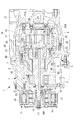
図1は、本発明の実施形態に係るスクロール圧縮機の縦断面図である。このスクロール圧縮機1は、例えばエンジン等の外部駆動源によって駆動される開放型(駆動軸が外部に突出している形式)の圧縮機であり、有底形状をなすフロントハウジング3とリアハウジング4とが複数のボルト5により一体に結合された円筒容器状のハウジング2を備えている。
Embodiments of the present invention will be described below with reference to the drawings.
FIG. 1 is a longitudinal sectional view of a scroll compressor according to an embodiment of the present invention. The
ハウジング2内部のフロントハウジング3側の開口端側には、軸受部材6が固定され、この軸受部材6のラジアル軸受部6Aと、フロントハウジング3内に設置された転がり軸受8とによって駆動軸9が回転自在に支持されている。軸受部材6はフランジ状の固定部6Bを備えており、この固定部6Bが複数のボルト7によってフロントハウジング3に締結固定されている。駆動軸9の一端部は、フロントハウジング3を貫通して外部に突出しており、その突出部位にエンジン等の外部駆動源からの動力がプーリ10および電磁クラッチ11を介して入力されるようになっている。
A
プーリ10は、フロントハウジング3の前端面にボルト12を介して固定された鍔部材13の外周に転がり軸受14を介して回転自在に支持され、その内部に電磁クラッチ11のコイル組立15が組み込まれたものである。また、プーリ10と対向するように、電磁クラッチ11のアーマチュア組立16が、ボス部16Aを介して駆動軸9の外部突出端にボルト17により組み付けられている。更に、この鍔部材13の内周側には、駆動軸9の貫通部を密封シールするためのメカニカルシール18が設置されている。
The
ハウジング2内部のリアハウジング4側には圧縮機構19が組み込まれている。圧縮機構19は、ハウジング2の内部に固定された固定スクロール20と、この固定スクロール20に対向する旋回スクロール21とが180°位相をずらして噛み合わされ、両スクロール20,21間に一対の圧縮室22が形成されたものである。このような圧縮機構19自体は周知のものである。
A
固定スクロール20は、軸受部材6に複数のボルト23で締結固定されており、その端板20Aの背面とリアハウジング4の内面との間に吐出キャビティ26が形成されている。この固定スクロール20の端板20Aに、圧縮されたガスを吐出キャビティ26内に吐出する吐出ポート24と、その吐出ポート24を開閉する吐出弁25とが設けられている。また、リアハウジング4には、吐出キャビティ26内に吐出された圧縮ガスを外部に吐出する吐出口27が開口され、ここに冷凍サイクルを構成する吐出配管を接続可能としている。
The fixed
一方、旋回スクロール21は、その端板21Aの背面中央部に円筒状のボス部28が形成され、このボス部28に円筒状のドライブブッシュ29が軸受30を介して回転自在に嵌合され、さらにこのドライブブッシュ29の内周部に、駆動軸9の内端側に設けられた偏心ピン9Aが回転自在に嵌合されている。このため、駆動軸9が回転すると、偏心回転する偏心ピン9Aとドライブブッシュ29とを介して旋回スクロール21が偏心旋回駆動される。
On the other hand, the orbiting
また、旋回スクロール21は、その端板21Aの背面が、軸受部材6に複数のボルト31で固定された環状のスラストプレート32によって支持されるとともに、端板21Aの背面と軸受部材6との間に介装されたオルダムリンクまたはピンリング等からなる周知の自転阻止機構33により自転が阻止され、固定スクロール20に対して公転旋回駆動するようになっている。
Further, the orbiting
リアハウジング4の前端側の外周に、冷凍サイクル側の吸入配管を接続する吸入口34が設けられており、該吸入口34から吸入キャビティ35内に吸入された低圧ガスが圧縮機構19の圧縮室22に吸い込まれて圧縮され、吐出ポート24(吐出弁25)と吐出キャビティ26とを経て吐出口27から吐出される構成となっている。
A
圧縮機構19の作動時には、圧縮室22内で圧縮された冷媒の反力により、旋回スクロール21が固定スクロール20から離れる方向(スラスト方向)に押圧される。このため、旋回スクロール21の端板21Aの背面がスラストプレート32のスラスト軸受面32Sに押し付けられ、そのスラスト力がスラストプレート32によって受け止められる。端板21Aとスラストプレート32との間には図示しない給油通路から潤滑油が供給され、これにより両部材21A,32間がスムーズに相対摺動可能になる。
During operation of the
上記のように、旋回スクロール21は固定スクロール20に対し偏心旋回運動するため、そのままでは重量アンバランスにより駆動軸9に回転振動が発生する。この重量アンバランスを解消するために、駆動軸9には、旋回スクロール21の偏心方向とは逆方向に錘を配置したメインバランスウェイト41とサブバランスウェイト42とが軸支されている。
As described above, the orbiting
メインバランスウェイト41は、ドライブブッシュ29を介して駆動軸9の偏心ピン9Aに軸支されており、軸受部材6の内周側に形成されたバランスウェイト収容室6Cに収容されて周方向に旋回する。また、サブバランスウェイト42は、軸受部材6のラジアル軸受部6Aと転がり軸受8との間において駆動軸9の中間部に設置され、軸受部材6の外周側に形成されたバランスウェイト収容室6Dに収容されて周方向に旋回する。
The
つまり、メインバランスウェイト41とサブバランスウェイト42は、軸受部材6に対し、軸方向の一方と他方に隣接して設けられている。換言すると、メインバランスウェイト41とサブバランスウェイト42との間に軸受部材6が挟まるレイアウトとなっている。これらのバランスウェイト41,42を設けることにより、旋回スクロール21の偏心旋回運動に伴う遠心力が打ち消されて回転振動が抑制される。
That is, the
[第1実施形態]
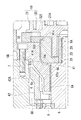
図2は、図1中のII部を拡大して本発明の第1実施形態を示すスラストプレート32およびメイン・サブバランスウェイト41,42付近の縦断面図である。
前述のように、メインバランスウェイト41は軸受部材6に対し軸方向に隣接するように駆動軸9に設けられるとともに、軸受部材6の径方向内周側に重なる内周オーバーラップ部41Aを有している。この内周オーバーラップ部41Aの部分が実質的な錘部分となってバランスウェイト収容室6C内を周方向に旋回する。内周オーバーラップ部41Aの、スラストプレート32側の端部における外周面にはC面取り状の外径縮小部41aが形成されている。この外径縮小部41aは、スラストプレート32側に向かって外径が漸減する外側円錐面状である。
[First Embodiment]
FIG. 2 is an enlarged longitudinal sectional view of the vicinity of the
As described above, the
一方、スラストプレート32は、そのメインバランスウェイト41(内周オーバーラップ部41A)側の内径部にC面取り状の内径拡大部32aが形成されている。この内径拡大部32aは、メインバランスウェイト41(41A)側に向かって内径が漸増する内側円錐面状である。メインバランスウェイト41(41A)の外径縮小部41aと、スラストプレート32の内径拡大部32aは、径方向および軸方向に重なっており、所定の間隔を空けて平行に対向している。
On the other hand, the
外径縮小部41aと内径拡大部32aの円錐面の傾斜角は、駆動軸9の軸線を基準に30度から60度程度に設定される。この内径拡大部32aの斜面がスラスト軸受面32Sに掛かるとスラスト軸受面32Sの内径が拡大されてスラスト軸受面32Sの面積が減少してしまうため、内径拡大部32aの斜面とスラスト軸受面32Sとが交差しないように内径拡大部32aの傾斜角度を設定するのが好ましい。
The inclination angles of the conical surfaces of the outer
スラストプレート32はボルト31(図1参照)によって軸受部材6に着脱可能に固定されているため、ボルト31を緩めてスラストプレート32を取り外すことにより、メインバランスウェイト41をバランスウェイト収容室6Cに対して着脱することができる。
Since the
メインバランスウェイト41の内周オーバーラップ部41Aにおけるラジアル軸受部6A側の端部にもC面取り状の外径縮小部41bが形成されている。この外径縮小部41bは、軸方向でラジアル軸受部6A側に向かって外径が漸減する外側円錐面状である。
A C chamfered outer
一方、軸受部材6には内径拡大部6aが形成されている。この内径拡大部6aは、内周オーバーラップ部41A側に向かって内径が漸増する内側円錐面状である。この内径拡大部6aと、内周オーバーラップ部41Aの外径縮小部41bとは軸方向および径方向に重なっており、所定の間隔を空けて平行に対向している。
On the other hand, the bearing
サブバランスウェイト42は、軸方向で軸受部材6に対しメインバランスウェイト41の反対側に位置して軸方向に隣接するように設けられており、軸受部材6の径方向外周側に重なる外周オーバーラップ部42Aを有している。この外周オーバーラップ部42Aの部分が実質的な錘部分となってバランスウェイト収容室6D内を周方向に旋回する。外周オーバーラップ部42Aは、軸方向で軸受部材6の固定部6B側に向かって内径が漸増する内側円錐面状の内径拡大部42aを有している。
The
他方、軸受部材6には、サブバランスウェイト42の外周オーバーラップ部42A側に向かって外径が漸減する外径縮小部6bが形成されており、この外径縮小部6bと外周オーバーラップ部42Aの内径拡大部42aとが軸方向および径方向に重なっており、所定の間隔を空けて平行に対向している。
On the other hand, the bearing
以上のように構成されたスクロール圧縮機1により、以下の作用効果が奏される。
即ち、このスクロール圧縮機1では、メインバランスウェイト41(内周オーバーラップ部41A)の、スラストプレート32側の端部に、該スラストプレート32側に向かって外径が小さくなる外径縮小部41aが形成される一方、スラストプレート32の、メインバランスウェイト41(41A)側の内径部に、該メインバランスウェイト41側に向かって内径が大きくなる内径拡大部32aが形成され、メインバランスウェイト41の外径縮小部41aと、スラストプレート32の内径拡大部32aとが径方向および軸方向に重ねられている。
The
That is, in the
上記構成によれば、スラストプレート32の内径寸法が、内径拡大部32aによってスラスト軸受面32S側からメインバランスウェイト41(41A)側に向かって大きくなる。このため、スラスト軸受面32Sの面積を所定の大きさに保ちながら、スラストプレート32に隣接するバランスウェイト収容室6Cの容積を径方向および軸方向の両方向に拡大することができる。
According to the above configuration, the inner diameter of the
上記のように、メインバランスウェイト41の外径縮小部41aがスラストプレート32の内径拡大部32aに対して径方向および軸方向に重なっているため、メインバランスウェイト41の軸方向寸法をスラストプレート32側に伸ばしながら、その径方向寸法も大きくすることができる。
As described above, since the outer
スラストプレート32においては、メインバランスウェイト41(41A)の外径拡大に伴ってスラスト軸受面32Sの面積(径方向の幅)が小さくなることがなく、旋回スクロール21(端板21A)とスラストプレート32(スラスト軸受面32S)との接触面積を十分に確保することができる。
In the
したがって、スラストプレート32におけるスラスト軸受面32Sの面積を減少させることなく、メインバランスウェイト41(41A)の寸法形状を大きくし、圧縮機構19の容量増大に対応することができる。
Therefore, the size and shape of the main balance weight 41 (41A) can be increased without reducing the area of the
メインバランスウェイト41(41A)の外径縮小部41aは、外側円錐面状とされ、スラストプレート32の内径拡大部32aは、外径縮小部41aに対し間隔を空けて平行に対向する内側円錐面状とされている。このため、メインバランスウェイト41の外径縮小部41aを、スラストプレート32の内径拡大部32aに無理なく近付けてメインバランスウェイト41(41A)の寸法形状を大きくし、圧縮機構19の容量増大に対応することができる。
The outer
メインバランスウェイト41の内周オーバーラップ部41Aは、軸受部材6の径方向内周側に重なっており、この内周オーバーラップ部41Aには、軸方向でラジアル軸受部6A側に向かって外径が漸減する外径縮小部41bが形成される一方、軸受部材6には内周オーバーラップ部41A側に向かって内径が漸増する内径拡大部6aが形成され、この内径拡大部6aと外径縮小部41bとが軸方向および径方向に重ねられている。
The inner
上記構成によれば、軸受部材6の中間部の外径、即ちラジアル軸受部6Aと固定部6Bとの間の部分の外径が、内径拡大部6aの斜面形状により、メインバランスウェイト41の内周オーバーラップ部41A側に向かって円錐筒状に拡径する。このため、例えば図2中に想像線Eで描いたように、内径拡大部6aの部分を軸方向に直交する平面と軸方向に平行する円筒面とで構成した場合に比べ、軸受部材6に肉厚の薄い部分が発生しない。よって、軸受部材6の強度が高く保たれ、撓み量の低減を図れる。したがって、簡素な構成により、軸受部材6の強度を低下させることなく、メインバランスウェイト41(内周オーバーラップ部41A)の寸法形状を大きくして圧縮機構19の容量増大に対応することができる。
According to the above configuration, the outer diameter of the intermediate portion of the bearing
駆動軸9には、メインバランスウェイト41とは別体のサブバランスウェイト42が、軸受部材6に対し、メインバランスウェイト41の反対側に位置して軸方向に隣接するように設けられている。このサブバランスウェイト42は軸受部材6の径方向外周側に重なる外周オーバーラップ部42Aを有し、該外周オーバーラップ部42Aには、軸方向で該軸受部材6の固定部6B側に向かって内径が漸増する内径拡大部42aが形成されている。一方、軸受部材6には、外周オーバーラップ部42A側に向かって外径が漸減する外径縮小部6bが形成されており、この外径縮小部6bと内径拡大部42aとが軸方向および径方向に重ねられている。
A
上記構成によれば、軸受部材6の中間部の外径が、外径縮小部6bの斜面形状により、バランスウェイト42の外周オーバーラップ部42A側に向かって円錐筒状に変化する。このため、例えば図2中に想像線Fで描いたように、外径縮小部6bの部分を軸方向に直交する平面と軸方向に平行する円筒面とで構成した場合に比べ、軸受部材6に肉厚の薄い部分が発生しない。よって、軸受部材6の強度が高く保たれ、撓み量の低減を図れる。したがって、簡素な構成により、軸受部材6の強度を低下させることなく、サブバランスウェイト42(外周オーバーラップ部42A)の寸法形状を大きくして圧縮機構19の容量増大に対応することができる。
According to the above configuration, the outer diameter of the intermediate portion of the bearing
[第2実施形態]
図3は、本発明の第2実施形態を示すスラストプレート32およびメイン・サブバランスウェイト41,42付近の縦断面図である。この図3においては、スラストプレート32の内周面の形状と、メインバランスウェイト41(内周オーバーラップ部41A)のスラストプレート32側の端部形状とが図2に示す第1実施形態の構成と異なり、それ以外は図2と同一の構成である。このため、同一構成部には図2と同一の符号を付して説明を省略する。
[Second Embodiment]
FIG. 3 is a longitudinal sectional view of the vicinity of the
この第2実施形態では、メインバランスウェイト41(41A)の、スラストプレート32側の端部に、少なくとも1段の段部を持つ外側段付き円筒面状の外径縮小部41cが形成されている。また、スラストプレート32には、外径縮小部(41c)に対し間隔を空けて噛み合う内側段付き円筒面状の内径拡大部32bが形成されている。
In the second embodiment, an outer diameter reduced
これにより、第1実施形態(図2)におけるメインバランスウェイト41(41A)の外側円錐面状の外径縮小部41aおよびスラストプレート32の内側円錐面状の内径拡大部32aの組み合わせと同じく、メインバランスウェイト41(41A)の外径縮小部41cを、スラストプレート32の内径拡大部32bに無理なく近付けてメインバランスウェイト41(41A)の寸法形状を径方向および軸方向に大きくし、圧縮機構19の容量増大に対応することができる。
Thereby, the main balance weight 41 (41A) in the first embodiment (FIG. 2) is similar to the combination of the outer conical outer
外径縮小部41cおよび内径拡大部32bを段付き円筒面状に形成することにより、第1実施形態における円錐面状の外径縮小部41aおよび内径拡大部32aよりも加工を容易にすることができる。なお、外径縮小部41cと内径拡大部32bに2段以上の段を形成してもよい。
By forming the outer diameter reduced
また、この段付き円筒面状の構成を、軸受部材6の内径拡大部6aとメインバランスウェイト41(41A)の外径縮小部41bとの対向部や、軸受部材6の外径縮小部6bとサブバランスウェイト42(42A)の内径拡大部42aとの対向部に適用してもよい。
In addition, this stepped cylindrical surface configuration is configured such that the inner diameter enlarged
なお、本発明は上記実施形態の構成のみに限定されるものではなく、適宜変更や改良を加えることができ、このように変更や改良を加えた実施形態も本発明の権利範囲に含まれるものとする。
例えば、上記実施形態では、外部動力によって駆動軸9が回転駆動される開放型のスクロール圧縮機1に本発明を適用した例について説明したが、内蔵した電動モータにより駆動軸を回転駆動する密閉型のスクロール圧縮機にも本発明を適用することができる。
It should be noted that the present invention is not limited to the configuration of the above-described embodiment, and can be appropriately changed or improved. Embodiments with such changes and improvements are also included in the scope of the right of the present invention. And
For example, in the above-described embodiment, the example in which the present invention is applied to the
1 スクロール圧縮機
2 ハウジング
6 軸受部材(メイン軸受)
6A ラジアル軸受部
6B 軸受部材の固定部
6a 内径拡大部
6b 外径縮小部
9 駆動軸
20 固定スクロール
21 旋回スクロール
21A 旋回スクロールの端板
32 スラストプレート
32S スラスト軸受面
32a,32b 内径拡大部
41 メインバランスウェイト
41A 内周オーバーラップ部
41a,41b,41c 外径縮小部
42 サブバランスウェイト
42A 外周オーバーラップ部
42a 内径拡大部
1 Scroll compressor 2
6A
Claims (5)
前記固定スクロールに対向して噛み合う旋回スクロールと、
前記旋回スクロールを偏心旋回運動させる駆動軸と、
前記ハウジング内部に設けられて前記駆動軸を支持する軸受部材と、
前記ハウジング内部に設置されてそのスラスト軸受面が前記旋回スクロールの端板背面に接し、前記旋回スクロールに作用するスラスト力を受け止める環状のスラストプレートと、
前記駆動軸に設けられて前記スラストプレートに対して軸方向に隣接し、前記旋回スクロールの偏心旋回運動に伴う遠心力を打ち消すメインバランスウェイトと、
を備え、
前記メインバランスウェイトは、その前記スラストプレート側の端部に、該スラストプレート側に向かって外径が漸減する外径縮小部を有し、
前記スラストプレートは、その内径部の前記メインバランスウェイト側に、該メインバランスウェイト側に向かって内径が漸増する内径拡大部を有し、
前記外径縮小部と前記内径拡大部とが径方向および軸方向に重なっているスクロール圧縮機。 A fixed scroll fixed inside the housing;
A orbiting scroll that meshes against the fixed scroll; and
A drive shaft for eccentrically orbiting the orbiting scroll;
A bearing member provided inside the housing and supporting the drive shaft;
An annular thrust plate that is installed inside the housing and whose thrust bearing surface is in contact with the back of the end plate of the orbiting scroll and receives the thrust force acting on the orbiting scroll;
A main balance weight that is provided on the drive shaft and is adjacent to the thrust plate in the axial direction, and cancels centrifugal force associated with the eccentric orbiting motion of the orbiting scroll;
With
The main balance weight has an outer diameter reducing portion whose outer diameter gradually decreases toward the thrust plate side at an end portion of the thrust plate side,
The thrust plate has an inner diameter enlarged portion whose inner diameter gradually increases toward the main balance weight side on the main balance weight side of the inner diameter portion,
A scroll compressor in which the outer diameter reduced portion and the inner diameter enlarged portion overlap in a radial direction and an axial direction.
該内周オーバーラップ部は、軸方向で該軸受部材のラジアル軸受部側に向かって外径が漸減する外径縮小部を有し、
前記軸受部材は、前記内周オーバーラップ部側に向かって内径が漸増する内径拡大部を有し、
前記外径縮小部と前記内径拡大部とが軸方向および径方向に重なっている請求項1から3のいずれかに記載のスクロール圧縮機。 The main balance weight is provided so as to be adjacent to the bearing member in the axial direction, and has an inner circumferential overlap portion that overlaps the radially inner circumferential side of the bearing member,
The inner circumferential overlap portion has an outer diameter reduction portion in which the outer diameter gradually decreases toward the radial bearing portion side of the bearing member in the axial direction,
The bearing member has an inner diameter enlarged portion in which an inner diameter gradually increases toward the inner circumferential overlap portion side,
The scroll compressor according to any one of claims 1 to 3, wherein the outer diameter reduced portion and the inner diameter enlarged portion overlap in an axial direction and a radial direction.
該サブバランスウェイトは、前記軸受部材に対し、前記メインバランスウェイトの反対側に位置して軸方向に隣接するように設けられるとともに、該軸受部材の径方向外周側に重なる外周オーバーラップ部を有し、
該外周オーバーラップ部は、軸方向で該軸受部材の固定部側に向かって内径が漸増する内径拡大部を有し、
前記軸受部材は、前記外周オーバーラップ部側に向かって外径が漸減する外径縮小部を有し、
前記内径拡大部と前記外径縮小部とが軸方向および径方向に重なっている請求項1から4のいずれかに記載のスクロール圧縮機。 Further comprising a sub balance weight separate from the main balance weight,
The sub-balance weight is provided on the opposite side of the main balance weight with respect to the bearing member so as to be adjacent to the axial direction, and has an outer peripheral overlap portion that overlaps the radial outer peripheral side of the bearing member. And
The outer peripheral overlap portion has an inner diameter enlarged portion whose inner diameter gradually increases in the axial direction toward the fixed portion side of the bearing member,
The bearing member has an outer diameter reducing portion in which an outer diameter gradually decreases toward the outer peripheral overlap portion side,
The scroll compressor according to any one of claims 1 to 4, wherein the inner diameter enlarged portion and the outer diameter reduced portion overlap in an axial direction and a radial direction.
Priority Applications (6)
| Application Number | Priority Date | Filing Date | Title |
|---|---|---|---|
| JP2016030061A JP6704751B2 (en) | 2016-02-19 | 2016-02-19 | Scroll compressor |
| CN201780005700.1A CN108431419A (en) | 2016-02-19 | 2017-02-01 | Screw compressor |
| EP17752966.6A EP3388673A4 (en) | 2016-02-19 | 2017-02-01 | Scroll compressor |
| PCT/JP2017/003546 WO2017141703A1 (en) | 2016-02-19 | 2017-02-01 | Scroll compressor |
| AU2017220218A AU2017220218B2 (en) | 2016-02-19 | 2017-02-01 | Scroll compressor |
| KR1020187019943A KR20180094056A (en) | 2016-02-19 | 2017-02-01 | Scroll compressor |
Applications Claiming Priority (1)
| Application Number | Priority Date | Filing Date | Title |
|---|---|---|---|
| JP2016030061A JP6704751B2 (en) | 2016-02-19 | 2016-02-19 | Scroll compressor |
Publications (2)
| Publication Number | Publication Date |
|---|---|
| JP2017145806A true JP2017145806A (en) | 2017-08-24 |
| JP6704751B2 JP6704751B2 (en) | 2020-06-03 |
Family
ID=59625790
Family Applications (1)
| Application Number | Title | Priority Date | Filing Date |
|---|---|---|---|
| JP2016030061A Active JP6704751B2 (en) | 2016-02-19 | 2016-02-19 | Scroll compressor |
Country Status (6)
| Country | Link |
|---|---|
| EP (1) | EP3388673A4 (en) |
| JP (1) | JP6704751B2 (en) |
| KR (1) | KR20180094056A (en) |
| CN (1) | CN108431419A (en) |
| AU (1) | AU2017220218B2 (en) |
| WO (1) | WO2017141703A1 (en) |
Cited By (2)
| Publication number | Priority date | Publication date | Assignee | Title |
|---|---|---|---|---|
| JP2020105933A (en) * | 2018-12-26 | 2020-07-09 | 株式会社豊田自動織機 | Electric compressor |
| KR102949917B1 (en) * | 2020-12-01 | 2026-04-10 | 주식회사 두원공조 | Scroll compressor |
Families Citing this family (1)
| Publication number | Priority date | Publication date | Assignee | Title |
|---|---|---|---|---|
| CN116838604A (en) * | 2022-03-23 | 2023-10-03 | 日立江森自控空调有限公司 | compressor |
Family Cites Families (11)
| Publication number | Priority date | Publication date | Assignee | Title |
|---|---|---|---|---|
| JPS60166782A (en) * | 1985-01-25 | 1985-08-30 | Hitachi Ltd | scroll fluid machine |
| JPS61205386A (en) * | 1985-03-08 | 1986-09-11 | Hitachi Ltd | Enclosed type scroll compressor |
| JPH0463984A (en) * | 1990-07-02 | 1992-02-28 | Mitsubishi Electric Corp | Scroll compressor |
| JP3147676B2 (en) * | 1994-09-20 | 2001-03-19 | 株式会社日立製作所 | Scroll compressor |
| JP3874469B2 (en) * | 1996-10-04 | 2007-01-31 | 株式会社日立製作所 | Scroll compressor |
| JP4123551B2 (en) * | 1997-11-17 | 2008-07-23 | 株式会社日立製作所 | Scroll compressor |
| JP2001329967A (en) * | 2000-05-24 | 2001-11-30 | Toyota Industries Corp | Seal structure of scroll type compressor |
| JP5550419B2 (en) | 2010-03-31 | 2014-07-16 | 三菱重工業株式会社 | Compressor |
| JP5304868B2 (en) * | 2011-09-30 | 2013-10-02 | ダイキン工業株式会社 | Scroll compressor |
| JP6118159B2 (en) * | 2013-04-08 | 2017-04-19 | サンデンホールディングス株式会社 | Scroll compressor |
| JP6628957B2 (en) * | 2014-02-28 | 2020-01-15 | 三菱重工業株式会社 | Scroll compressor |
-
2016
- 2016-02-19 JP JP2016030061A patent/JP6704751B2/en active Active
-
2017
- 2017-02-01 WO PCT/JP2017/003546 patent/WO2017141703A1/en not_active Ceased
- 2017-02-01 EP EP17752966.6A patent/EP3388673A4/en not_active Withdrawn
- 2017-02-01 KR KR1020187019943A patent/KR20180094056A/en not_active Ceased
- 2017-02-01 CN CN201780005700.1A patent/CN108431419A/en active Pending
- 2017-02-01 AU AU2017220218A patent/AU2017220218B2/en not_active Expired - Fee Related
Cited By (3)
| Publication number | Priority date | Publication date | Assignee | Title |
|---|---|---|---|---|
| JP2020105933A (en) * | 2018-12-26 | 2020-07-09 | 株式会社豊田自動織機 | Electric compressor |
| JP7151470B2 (en) | 2018-12-26 | 2022-10-12 | 株式会社豊田自動織機 | electric compressor |
| KR102949917B1 (en) * | 2020-12-01 | 2026-04-10 | 주식회사 두원공조 | Scroll compressor |
Also Published As
| Publication number | Publication date |
|---|---|
| AU2017220218B2 (en) | 2019-07-04 |
| EP3388673A4 (en) | 2018-11-07 |
| EP3388673A1 (en) | 2018-10-17 |
| CN108431419A (en) | 2018-08-21 |
| WO2017141703A1 (en) | 2017-08-24 |
| AU2017220218A1 (en) | 2018-07-19 |
| JP6704751B2 (en) | 2020-06-03 |
| KR20180094056A (en) | 2018-08-22 |
Similar Documents
| Publication | Publication Date | Title |
|---|---|---|
| JP5851851B2 (en) | Scroll compressor | |
| JP5386219B2 (en) | Scroll compressor | |
| JP6685690B2 (en) | Scroll fluid machinery | |
| JP5681019B2 (en) | Scroll type fluid machine | |
| JPWO2017158665A1 (en) | Scroll compressor | |
| JP2017145806A (en) | Scroll compressor | |
| US20130121864A1 (en) | Scroll compressor | |
| JP6734378B2 (en) | Scroll type fluid machine and its assembly method | |
| JP4625590B2 (en) | Scroll type fluid machinery | |
| CN107882738B (en) | Compressor with a compressor housing having a plurality of compressor blades | |
| JP6685689B2 (en) | Scroll fluid machinery | |
| JP6906887B2 (en) | Scroll fluid machine | |
| JP7233935B2 (en) | scroll type fluid machinery | |
| JP2018096253A (en) | Scroll compressor | |
| JP2014088852A (en) | Scroll type compressor | |
| JP2972464B2 (en) | Scroll type fluid machine | |
| JP7791730B2 (en) | Scroll Compressor | |
| JP6918864B2 (en) | Scroll type fluid machine and its maintenance method, assembly method | |
| JP7483638B2 (en) | Scroll Compressor | |
| JP2007327438A (en) | Scroll compressor | |
| JP2011169284A (en) | Scroll type compressor | |
| JP2013181443A (en) | Scroll type fluid machine | |
| JP2004263604A (en) | Scroll type fluid machine | |
| JP2014047673A (en) | Bearing structure and scroll compressor | |
| JP2016075200A (en) | Scroll type fluid machine |
Legal Events
| Date | Code | Title | Description |
|---|---|---|---|
| A711 | Notification of change in applicant |
Free format text: JAPANESE INTERMEDIATE CODE: A712 Effective date: 20180705 |
|
| A625 | Written request for application examination (by other person) |
Free format text: JAPANESE INTERMEDIATE CODE: A625 Effective date: 20181218 |
|
| A131 | Notification of reasons for refusal |
Free format text: JAPANESE INTERMEDIATE CODE: A131 Effective date: 20191126 |
|
| A601 | Written request for extension of time |
Free format text: JAPANESE INTERMEDIATE CODE: A601 Effective date: 20200107 |
|
| A521 | Written amendment |
Free format text: JAPANESE INTERMEDIATE CODE: A523 Effective date: 20200325 |
|
| TRDD | Decision of grant or rejection written | ||
| A01 | Written decision to grant a patent or to grant a registration (utility model) |
Free format text: JAPANESE INTERMEDIATE CODE: A01 Effective date: 20200414 |
|
| A61 | First payment of annual fees (during grant procedure) |
Free format text: JAPANESE INTERMEDIATE CODE: A61 Effective date: 20200513 |
|
| R150 | Certificate of patent or registration of utility model |
Ref document number: 6704751 Country of ref document: JP Free format text: JAPANESE INTERMEDIATE CODE: R150 |