JP2017146055A - Air conditioner - Google Patents
Air conditioner Download PDFInfo
- Publication number
- JP2017146055A JP2017146055A JP2016029414A JP2016029414A JP2017146055A JP 2017146055 A JP2017146055 A JP 2017146055A JP 2016029414 A JP2016029414 A JP 2016029414A JP 2016029414 A JP2016029414 A JP 2016029414A JP 2017146055 A JP2017146055 A JP 2017146055A
- Authority
- JP
- Japan
- Prior art keywords
- blower
- wind direction
- air
- direction plate
- air conditioner
- Prior art date
- Legal status (The legal status is an assumption and is not a legal conclusion. Google has not performed a legal analysis and makes no representation as to the accuracy of the status listed.)
- Granted
Links
Images


Classifications
-
- F—MECHANICAL ENGINEERING; LIGHTING; HEATING; WEAPONS; BLASTING
- F24—HEATING; RANGES; VENTILATING
- F24F—AIR-CONDITIONING; AIR-HUMIDIFICATION; VENTILATION; USE OF AIR CURRENTS FOR SCREENING
- F24F13/00—Details common to, or for air-conditioning, air-humidification, ventilation or use of air currents for screening
- F24F13/20—Casings or covers
-
- F—MECHANICAL ENGINEERING; LIGHTING; HEATING; WEAPONS; BLASTING
- F24—HEATING; RANGES; VENTILATING
- F24F—AIR-CONDITIONING; AIR-HUMIDIFICATION; VENTILATION; USE OF AIR CURRENTS FOR SCREENING
- F24F1/00—Room units for air-conditioning, e.g. separate or self-contained units or units receiving primary air from a central station
- F24F1/0007—Indoor units, e.g. fan coil units
- F24F1/0011—Indoor units, e.g. fan coil units characterised by air outlets
-
- F—MECHANICAL ENGINEERING; LIGHTING; HEATING; WEAPONS; BLASTING
- F24—HEATING; RANGES; VENTILATING
- F24F—AIR-CONDITIONING; AIR-HUMIDIFICATION; VENTILATION; USE OF AIR CURRENTS FOR SCREENING
- F24F1/00—Room units for air-conditioning, e.g. separate or self-contained units or units receiving primary air from a central station
- F24F1/0007—Indoor units, e.g. fan coil units
- F24F1/0043—Indoor units, e.g. fan coil units characterised by mounting arrangements
- F24F1/0057—Indoor units, e.g. fan coil units characterised by mounting arrangements mounted in or on a wall
-
- F—MECHANICAL ENGINEERING; LIGHTING; HEATING; WEAPONS; BLASTING
- F24—HEATING; RANGES; VENTILATING
- F24F—AIR-CONDITIONING; AIR-HUMIDIFICATION; VENTILATION; USE OF AIR CURRENTS FOR SCREENING
- F24F13/00—Details common to, or for air-conditioning, air-humidification, ventilation or use of air currents for screening
- F24F13/08—Air-flow control members, e.g. louvres, grilles, flaps or guide plates
- F24F13/10—Air-flow control members, e.g. louvres, grilles, flaps or guide plates movable, e.g. dampers
- F24F13/14—Air-flow control members, e.g. louvres, grilles, flaps or guide plates movable, e.g. dampers built up of tilting members, e.g. louvre
Landscapes
- Engineering & Computer Science (AREA)
- Chemical & Material Sciences (AREA)
- Combustion & Propulsion (AREA)
- Mechanical Engineering (AREA)
- General Engineering & Computer Science (AREA)
- Air-Conditioning Room Units, And Self-Contained Units In General (AREA)
- Air Filters, Heat-Exchange Apparatuses, And Housings Of Air-Conditioning Units (AREA)
- Air-Flow Control Members (AREA)
Abstract
【課題】送風回路の内部に、送風機と熱交換器とリアガイダとスタビライザを備える室内ユニットにおいて、本体ケーシングの前面から略水平方向へ気流を吹き出すことができ、吹出口を天井近傍に位置するように構成することで効率的に室内に天井気流を形成し、快適な室内気流形成の効果が得られる空気調和機を提供する。【解決手段】空気調和機100は、送風回路105内に送風機106とスタビライザ107とリアガイダ108と熱交換器109とを備え、吹出口104が本体ケーシング102の前面に、天井近傍に位置するように略水平方向に構成され、吸込口103が吹出口104の下方面に構成され、スタビライザ107と連続面で構成される第1風向板110と、リアガイダ108と連続面で構成される第2風向板111とを備える。【選択図】図1In an indoor unit including a blower, a heat exchanger, a rear guider, and a stabilizer inside a blower circuit, an air flow can be blown in a substantially horizontal direction from a front surface of a main body casing, and a blower outlet is positioned near a ceiling. By configuring, an air conditioner that efficiently forms a ceiling air flow in a room and obtains a comfortable indoor air flow formation effect is provided. An air conditioner (100) includes a blower (106), a stabilizer (107), a rear guider (108), and a heat exchanger (109) in a blower circuit (105), so that a blower outlet (104) is located in front of a main casing (102) and in the vicinity of the ceiling. The first wind direction plate 110 is configured in a substantially horizontal direction, the suction port 103 is configured in the lower surface of the outlet 104, the stabilizer 107 and the continuous surface, and the rear guider 108 and the continuous surface. 111. [Selection] Figure 1
Description
本発明は、吸込口が吹出口の下方に構成され、略水平方向の吹出口に送風路から連続面で風向板が構成される、空気調和機に関する。 The present invention relates to an air conditioner in which a suction port is formed below a blower outlet, and a wind direction plate is formed on a substantially horizontal blower outlet by a continuous surface from an air passage.
一般に、吸込口と、吹出口を有する本体ケーシング内に通風させる送風回路を形成し、この送風回路内に送風機を備え、送風機の上流近傍に熱交換器を配し、送風機の回転によって吸込口から吸い込まれた空気を熱交換器を通して熱交換した後、吹出口より吹き出す室内ユニットを有する空気調和機が知られている。送風機の回転によって発生する空気の流れを形成するために、リアガイダと、スタビライザとを備える。ところで、送風機内部における空気の流れとして、送風機を通過して吹出口から吹き出される流れ(主流)と、送風機とスタビライザの間で発生して、スタビライザの先端で渦状に循環する流れ(渦流)が存在する。 In general, an air inlet circuit and a blower circuit for ventilating a main body casing having an air outlet are formed, a fan is provided in the air fan circuit, a heat exchanger is provided in the vicinity of the upstream of the air fan, and the air blower is rotated by the rotation of the air blower. 2. Description of the Related Art An air conditioner having an indoor unit that heat-exchanges sucked air through a heat exchanger and then blows out from a blower outlet is known. In order to form a flow of air generated by rotation of the blower, a rear guider and a stabilizer are provided. By the way, as the air flow in the blower, there are a flow (main flow) blown from the blower outlet through the blower and a flow (vortex flow) generated between the blower and the stabilizer and circulated in a spiral shape at the tip of the stabilizer. Exists.
ここで、従来の室内ユニットの一例として、特許文献1に開示されている空気調和機1について、図4を用いて説明する。空気調和機1は、本体ケーシング2の下面に吸込口3と、円弧状の前面に吹出口4と、吸込口3と吹出口4を結ぶ空気通路5と、前部熱交換器6と、後部熱交換器7と、熱交換された空気を吹出口4に送出する前部熱交換器6及び後部熱交換器7の上部に位置する送風機8と、凝縮水を受ける前部熱交換器6及び後部熱交換器7の下部に位置する露受皿9とを備え、前部熱交換器6の前面または下面に補助吸込口10を設けている。また、送風機8の上部と吹出口4の上部とを結ぶリアガイダ11を備え、送風機8の下部と吹出口4の下部とを結ぶスタビライザ12を備え、後部熱交換器7の上端と吸込口3の後部とを結ぶ隔壁13を備える。
Here, as an example of a conventional indoor unit, an
送風機8が回転することで、空気は前部熱交換器6及び後部熱交換器7を通り抜けるように吸い込まれ、送風機8を貫流し、スタビライザ12とリアガイダ11とで形成される空気通路を介して本体ケーシング2から吹き出される。その際、吸込口3を通過して隔壁13に沿って流れる空気が、後部熱交換器7を通り抜け、続けてリアガイダ11に沿って流れる。リアガイダ11は送風機8の上部では略水平の面を備え、そこから湾曲面を形成し、吹出口4では斜め下方向きの面を備え、かつスタビライザ12も吹出口4では斜め下方向きの面を備えているため、吹き出し空気の方向を斜め下方向きに制御することを目論んでいる。
As the
しかしながら、特許文献1に係る空気調和機1では、吹き出し空気の方向を斜め下方向きにすることができるが、水平方向吹出が困難となる。水平方向吹出が困難となると、室内に無気流感の領域を形成するための気流形成ができない等の、室内の気流環境の制御性に課題を伴うおそれがある。
However, in the
本発明は、上記した従来の問題点に鑑みてなされたものであって、吸込口と、吹出口を有する本体ケーシング内に通風させる送風回路の内部に送風機を備え、送風機の上流近傍に熱交換器を配し、送風機の回転によって発生する空気の流れを形成するために、リアガ
イダと、スタビライザとを備える室内ユニットにおいて、吹出口からの気流の吹き出し方向を水平方向に制御し、室内の気流環境の制御性を向上させることのできる空気調和機の提供を目的とする。
The present invention has been made in view of the above-described conventional problems, and is provided with a blower inside a blower circuit that ventilates a main body casing having a suction port and a blower outlet, and performs heat exchange near the upstream of the blower. In order to form a flow of air generated by rotation of the blower, an indoor unit including a rear guider and a stabilizer is used to control the blowing direction of the airflow from the outlet in the horizontal direction, and the indoor airflow environment An object of the present invention is to provide an air conditioner that can improve controllability.
本発明の空気調和機は、吸込口と吹出口と、前記吸込口と前記吹出口とを結ぶ送風回路と、前記送風回路に送風機とスタビライザとリアガイダとを具備する本体ケーシングを備えた空気調和機であって、前記吹出口は前記本体ケーシングの前面に略水平方向に送風するよう構成され、前記吸込口は前記吹出口より下方に位置し、風向板が前記吹出口の送風路の少なくとも一部の壁面からの連続な面で構成したものである。 An air conditioner according to the present invention includes an air conditioner including a suction port, an air outlet, a blower circuit connecting the suction port and the blower port, and a main body casing including the blower, a stabilizer, and a rear guider. The air outlet is configured to blow air substantially horizontally to the front surface of the main body casing, the suction port is located below the air outlet, and a wind direction plate is at least part of the air passage of the air outlet. It consists of a continuous surface from the wall surface.
このことにより、風向板が吹出口に送風回路から連続面で構成されることで、吹出口を略水平方向に構成する空気調和機において、本体ケーシングの前面から略水平方向へ気流を吹き出すことができる。 Thus, in the air conditioner that configures the blowout port in a substantially horizontal direction by the wind direction plate being configured from the blower circuit to the blowout port, the airflow can be blown out from the front surface of the main body casing in the substantially horizontal direction. it can.
本発明に係る空気調和機は、本体ケーシングの前面から略水平方向へ気流を吹き出すことができ、吹出口を天井近傍に位置するように構成することで効率的に室内に天井気流を形成し、快適な室内気流形成の効果が得られる。 The air conditioner according to the present invention can blow an air flow in a substantially horizontal direction from the front surface of the main casing, and efficiently forms a ceiling air flow in the room by configuring the air outlet in the vicinity of the ceiling. A comfortable indoor airflow can be formed.
第1の発明は、吸込口と吹出口と、前記吸込口と前記吹出口とを結ぶ送風回路と、前記送風回路に送風機とスタビライザとリアガイダとを具備する本体ケーシングを備えた空気調和機であって、前記吹出口は前記本体ケーシングの前面に略水平方向に送風するよう構成され、前記吸込口は前記吹出口より下方に位置し、風向板が前記吹出口の送風路の少なくとも一部の壁面からの連続な面で構成したものである。 1st invention is an air conditioner provided with the main body casing which comprises a suction inlet, a blower outlet, the ventilation circuit which connects the said suction inlet, and the said blower outlet, and the said blower circuit is equipped with an air blower, a stabilizer, and a rear guider. The blower outlet is configured to blow air substantially horizontally to the front surface of the main body casing, the suction port is positioned below the blower outlet, and the airflow direction plate is a wall surface of at least a part of the blower passage of the blower outlet. It consists of a continuous surface from
これによれば、風向板が吹出口に送風回路から連続面で構成されることで、吹出口を略水平方向に構成する空気調和機において、本体ケーシングの前面から略水平方向へ気流を吹き出すことができ、吹出口を天井近傍に位置するように構成することで効率的に室内に天井気流を形成し、快適な室内気流が形成できる。 According to this, in the air conditioner which comprises a blower outlet in a substantially horizontal direction by a wind direction board being constituted from a blower circuit to a blower outlet, an air current is blown out from a front surface of a main body casing in a substantially horizontal direction. It is possible to form a ceiling air flow efficiently in the room by configuring the air outlet in the vicinity of the ceiling, and a comfortable indoor air flow can be formed.
第2の発明は、特に、第1の発明の空気調和機において、スタビライザの壁面の少なくとも一部と連続な面で構成される第1風向板と、リアガイダの壁面の少なくとも一部と連続な面で構成される第2風向板とを備えるものである。 In particular, in the air conditioner of the first invention, the second invention is a surface that is continuous with at least a portion of the wall surface of the rear guider, and a first wind direction plate that is formed of a surface continuous with at least a portion of the wall surface of the stabilizer. The 2nd wind direction board comprised by these is provided.
これによれば、吹出口と、吹出口の下方面に構成される吸込口との間に、第1風向板が配置されることで、吹出口から吹き出される気流が吸込口へ直接流入するショートサーキットを抑制し、本体ケーシングの前面から略水平方向へ効率的に気流を吹き出すことができ、快適な室内気流が形成できる。 According to this, the 1st wind direction board is arrange | positioned between a blower outlet and the suction inlet comprised in the lower surface of a blower outlet, and the airflow which blows off from a blower outlet flows in into a suction inlet directly. Short circuit can be suppressed, air current can be efficiently blown out from the front surface of the main body casing in a substantially horizontal direction, and a comfortable indoor air current can be formed.
第3の発明は、特に、第1の発明の空気調和機において、第2風向板を回転駆動させる駆動軸心を、吹出口の端部から、第2風向板の先端と前記駆動軸心との距離間隔を有する距離だけ離れた位置に備えるものである。 In particular, in the air conditioner according to the first aspect of the present invention, the third invention provides a drive shaft for rotating the second wind direction plate from the end of the air outlet to the tip of the second wind direction plate and the drive shaft center. It is provided at a position separated by a distance having a distance interval of.
これによれば、吹出口から吹き出す気流方向を第2風向板の回転駆動によって制御する際に、第1風向板との距離が狭まり風量が減少することを緩和し、吹き出す気流の方向によらず、風量を確保することができる。 According to this, when controlling the direction of the air flow blown out from the outlet by the rotational drive of the second wind direction plate, the distance from the first wind direction plate is reduced and the air volume is reduced, and the air flow direction is blown out. The air volume can be secured.
第4の発明は、特に、第1の発明の空気調和機において、第2風向板を駆動させる駆動腕を備え、前記第2風向板を前記駆動腕の先端に位置する駆動軸心を中心に回動するものである。 The fourth invention is the air conditioner of the first invention, in particular, provided with a drive arm for driving the second wind direction plate, with the second wind direction plate centered on a drive axis located at the tip of the drive arm. It rotates.
これによれば、吹出口から吹き出す気流方向を第2風向板の駆動腕を用いた駆動によって制御する際に、吹き出す気流方向によらず第1風向板と第2風向板との間隔を一定に保つことができ、吹き出す気流の方向によって風量が変化することを緩和し、吹き出す気流の方向によらず、風量を確保することができる。 According to this, when the direction of the air flow blown out from the outlet is controlled by driving using the driving arm of the second wind direction plate, the distance between the first wind direction plate and the second wind direction plate is made constant regardless of the direction of the air flow blown out. It can be maintained, and the change in the air volume according to the direction of the air flow to be blown out can be mitigated, and the air volume can be ensured regardless of the direction of the air flow to be blown out.
以下、本発明の各実施形態について、図面を参照して詳細に説明する。なお、以下に説明する各実施形態は一例であり、本発明は各実施形態により限定されるものではない。 Hereinafter, embodiments of the present invention will be described in detail with reference to the drawings. Each embodiment described below is an example, and the present invention is not limited to each embodiment.
(実施の形態1)
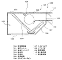
図1は、本実施形態に係る空気調和機100の構成の一例を示す断面図である。
(Embodiment 1)
FIG. 1 is a cross-sectional view illustrating an example of a configuration of an
空気調和機100の室内ユニット101は、図1に示すように、本体ケーシング102に、吸込口103と、吹出口104とを備え、本体ケーシング102の内部に送風回路105と、送風機106と、スタビライザ107と、リアガイダ108と、熱交換器109とを備え、吹出口104が本体ケーシング102の前面に、天井近傍に位置するように略水平方向に構成され、吸込口103が吹出口104の下方面に構成される。また、スタビライザ107と連続面で構成される第1風向板110と、リアガイダ108と連続面で構成される第2風向板111とを備える。第2風向板111の駆動軸心はリアガイダ108の先端にあたる吹出口104の端部に位置している。
As shown in FIG. 1, the
送風機106はブレード外周円の略接線方向に空気を吹き出し、送風機106を通過して吹出口104から吹き出される流れ(主流)と、送風機106とスタビライザ107の間で発生して渦状に循環する流れ(渦流)とを発生させる。吹出口104は、リアガイダ108とスタビライザ107とで、上下を挟まれて形成され、その吹き出し方向は略水平方向になっており、また、スタビライザ107と連続面で構成される第1風向板110と、リアガイダ108と連続面で構成される第2風向板111により、吸込口103にショートサーキットを生じることなく、室内へ吹き出すことができ、効率的に室内に天井気流を形成し、快適な室内気流が形成できる。
The
また、第1風向板110の駆動軸心は吹出口の端部にあたるスタビライザ107の先端に位置し、第2風向板111の駆動軸心は吹出口の端部にあたるリアガイダ108の先端に位置する。第1風向板110と第2風向板111とは、それぞれの駆動軸心を中心に回転駆動し、吹出口104から吹き出す気流の方向を制御する。
(実施の形態2)
図2は、本実施形態に係る空気調和機200の構成の一例を示す断面図である。図2において、実施の形態1と共通の要素については、共通の符号を付している。
The drive axis of the first
(Embodiment 2)
FIG. 2 is a cross-sectional view illustrating an example of the configuration of the
空気調和機200の室内ユニット101は、図2に示すように、第2風向板111を回転駆動させる駆動軸心を、吹出口104の端部から吹き出し方向へ、第2風向板111の先端と駆動軸心との間隔を有する距離だけ離れた位置に備えている。これによれば、吹出口104から吹き出す気流を水平方向へ吹き出す際には、第2風向板111を、その先端
がリアガイダ108の先端と突き合う位置に回転駆動する。また、吹出口104から吹き出す気流を第2風向板111によって斜下方向へ制御する際に、第2風向板111を、その先端が斜下方向へ向く位置に回転駆動する。これによれば、第2風向板111を回転駆動した際に、第2風向板111と第1風向板110との距離が狭まり風量が減少することを緩和し、吹き出す気流の方向によらず、風量を確保することができ、快適な室内気流が形成できる。
(実施の形態3)
図3は、本実施形態に係る空気調和機300の構成の一例を示す断面図である。図3において、実施の形態1と共通の要素については、共通の符号を付している。
As shown in FIG. 2, the
(Embodiment 3)
FIG. 3 is a cross-sectional view illustrating an example of the configuration of the
空気調和機300の室内ユニット101は、図3に示すように、駆動腕112が第2風向板111の左右両端を支持している。駆動腕112は駆動部を備えており、駆動部の動作によって吹き出し方向へと水平及び回転移動できる。この移動によって駆動腕112に支持された第2風向板111は水平及び回転移動できる。なお、駆動腕112による第2風向板111の支持部を第2風向板111の駆動軸心とすることで、駆動腕112による移動に加えて駆動軸心を中心とした回転が可能となる。吹出口104から吹き出す気流を水平方向へ吹き出す際には、第2風向板111を、リアガイダ108と連続面を構成する位置に駆動する。また、吹出口104から吹き出す気流を第2風向板111によって斜下方向へ制御する際に、第2風向板111を、その先端が斜下方向へ向く位置に駆動する。これによれば、第2風向板111を回転駆動した際に、第2風向板111と第1風向板110との距離が狭まり風量が減少することを緩和し、吹き出す気流の方向によらず、風量を確保することができ、快適な室内気流が形成できる。
In the
なお、本実施の形態では、送風機をクロスフローファンを例に述べたが、送風機はこれにとどまらず、ターボファンや軸流ファンなどその形式を問わない。 In the present embodiment, the blower is described by taking a cross flow fan as an example. However, the blower is not limited to this, and any type such as a turbo fan or an axial fan may be used.
本発明に係る空気調和機は、送風機が通風する空気量を増加できることから、家庭用空調や業務用空調に用いるのに好適である。 Since the air conditioner which concerns on this invention can increase the air quantity which a ventilation fan ventilates, it is suitable for using it for domestic air conditioning or commercial air conditioning.
100 空気調和機
101 室内ユニット
102 本体ケーシング
103 吸込口
104 吹出口
105 送風回路
106 送風機
107 スタビライザ
108 リアガイダ
109 熱交換器
110 第1風向板
111 第2風向板
112 駆動腕
DESCRIPTION OF
Claims (4)
Priority Applications (4)
| Application Number | Priority Date | Filing Date | Title |
|---|---|---|---|
| JP2016029414A JP6528131B2 (en) | 2016-02-19 | 2016-02-19 | Air conditioner |
| CN201680011032.9A CN107306505B (en) | 2016-02-19 | 2016-12-16 | Air conditioner |
| PCT/JP2016/005161 WO2017141297A1 (en) | 2016-02-19 | 2016-12-16 | Air conditioner |
| DE112016006451.9T DE112016006451T5 (en) | 2016-02-19 | 2016-12-16 | air conditioning |
Applications Claiming Priority (1)
| Application Number | Priority Date | Filing Date | Title |
|---|---|---|---|
| JP2016029414A JP6528131B2 (en) | 2016-02-19 | 2016-02-19 | Air conditioner |
Publications (2)
| Publication Number | Publication Date |
|---|---|
| JP2017146055A true JP2017146055A (en) | 2017-08-24 |
| JP6528131B2 JP6528131B2 (en) | 2019-06-12 |
Family
ID=59625639
Family Applications (1)
| Application Number | Title | Priority Date | Filing Date |
|---|---|---|---|
| JP2016029414A Expired - Fee Related JP6528131B2 (en) | 2016-02-19 | 2016-02-19 | Air conditioner |
Country Status (4)
| Country | Link |
|---|---|
| JP (1) | JP6528131B2 (en) |
| CN (1) | CN107306505B (en) |
| DE (1) | DE112016006451T5 (en) |
| WO (1) | WO2017141297A1 (en) |
Citations (6)
| Publication number | Priority date | Publication date | Assignee | Title |
|---|---|---|---|---|
| JPS6077952U (en) * | 1983-11-02 | 1985-05-31 | 三菱重工業株式会社 | air conditioner |
| JPH08327084A (en) * | 1995-06-01 | 1996-12-10 | Mitsubishi Heavy Ind Ltd | Ceiling suspended type air conditioner |
| JPH0914196A (en) * | 1995-06-30 | 1997-01-14 | Nippondenso Co Ltd | Once-through fans for automobile air conditioners |
| JPH09145139A (en) * | 1995-11-20 | 1997-06-06 | Mitsubishi Electric Corp | Air outlet |
| US5918666A (en) * | 1996-12-21 | 1999-07-06 | Lg Electronics, Inc. | Indoor unit for air conditioner |
| JP2009257640A (en) * | 2008-04-15 | 2009-11-05 | Panasonic Corp | Indoor unit of air conditioner |
Family Cites Families (7)
| Publication number | Priority date | Publication date | Assignee | Title |
|---|---|---|---|---|
| CN2883995Y (en) * | 2005-09-19 | 2007-03-28 | 松下电器产业株式会社 | A ducted air conditioner |
| JP4582122B2 (en) * | 2007-06-25 | 2010-11-17 | パナソニック株式会社 | Air conditioner |
| JP2010112600A (en) * | 2008-11-05 | 2010-05-20 | Daikin Ind Ltd | Indoor unit for air conditioning system and air conditioning system provided with the same |
| JP5043896B2 (en) * | 2009-07-17 | 2012-10-10 | パナソニック株式会社 | Air conditioner |
| JP5786687B2 (en) * | 2011-11-30 | 2015-09-30 | 株式会社富士通ゼネラル | Air conditioner |
| JP2015055419A (en) * | 2013-09-12 | 2015-03-23 | パナソニック株式会社 | Air conditioner |
| CN105202636A (en) * | 2015-10-14 | 2015-12-30 | 珠海格力电器股份有限公司 | Air conditioner refrigeration assembly, air conditioner and building structure |
-
2016
- 2016-02-19 JP JP2016029414A patent/JP6528131B2/en not_active Expired - Fee Related
- 2016-12-16 DE DE112016006451.9T patent/DE112016006451T5/en active Pending
- 2016-12-16 CN CN201680011032.9A patent/CN107306505B/en not_active Expired - Fee Related
- 2016-12-16 WO PCT/JP2016/005161 patent/WO2017141297A1/en not_active Ceased
Patent Citations (6)
| Publication number | Priority date | Publication date | Assignee | Title |
|---|---|---|---|---|
| JPS6077952U (en) * | 1983-11-02 | 1985-05-31 | 三菱重工業株式会社 | air conditioner |
| JPH08327084A (en) * | 1995-06-01 | 1996-12-10 | Mitsubishi Heavy Ind Ltd | Ceiling suspended type air conditioner |
| JPH0914196A (en) * | 1995-06-30 | 1997-01-14 | Nippondenso Co Ltd | Once-through fans for automobile air conditioners |
| JPH09145139A (en) * | 1995-11-20 | 1997-06-06 | Mitsubishi Electric Corp | Air outlet |
| US5918666A (en) * | 1996-12-21 | 1999-07-06 | Lg Electronics, Inc. | Indoor unit for air conditioner |
| JP2009257640A (en) * | 2008-04-15 | 2009-11-05 | Panasonic Corp | Indoor unit of air conditioner |
Also Published As
| Publication number | Publication date |
|---|---|
| WO2017141297A1 (en) | 2017-08-24 |
| JP6528131B2 (en) | 2019-06-12 |
| CN107306505A (en) | 2017-10-31 |
| DE112016006451T5 (en) | 2018-12-20 |
| CN107306505B (en) | 2020-03-17 |
Similar Documents
| Publication | Publication Date | Title |
|---|---|---|
| JP6932009B2 (en) | Indoor unit of air conditioner | |
| JP4013954B2 (en) | Air conditioner indoor unit | |
| JP4502057B2 (en) | Indoor unit of floor type air conditioner | |
| JP5030602B2 (en) | Air conditioner | |
| WO1999008050A1 (en) | Air outlet structure of air conditioners | |
| JP5383628B2 (en) | Air conditioner | |
| JP6429204B2 (en) | Air conditioner | |
| CN101858620A (en) | Indoor unit of air conditioner | |
| JP6776531B2 (en) | Indoor unit of air conditioner | |
| CN114402169B (en) | Air blower and air conditioner indoor unit | |
| WO2013035218A1 (en) | Air conditioner | |
| JP5834911B2 (en) | Air conditioning indoor unit | |
| KR20070060880A (en) | Air Conditioner and Control Method | |
| JP6233398B2 (en) | Indoor unit of air conditioner | |
| KR102332307B1 (en) | Air conditioner indoor unit, air conditioner and control method of air conditioner | |
| JP2017146055A (en) | Air conditioner | |
| JP2016038151A (en) | Air conditioner indoor unit | |
| JP2008020149A (en) | Air blower | |
| JP2002243186A (en) | Ceiling mounted air conditioner | |
| JP2005098557A (en) | Air conditioner | |
| JP2000220878A (en) | Air conditioning unit | |
| JP2007078285A (en) | Air conditioner indoor unit | |
| JP4684868B2 (en) | Fan coil unit | |
| JP2017040408A (en) | Air conditioner | |
| JP4775893B2 (en) | Air conditioner outdoor unit |
Legal Events
| Date | Code | Title | Description |
|---|---|---|---|
| A621 | Written request for application examination |
Free format text: JAPANESE INTERMEDIATE CODE: A621 Effective date: 20180219 |
|
| A131 | Notification of reasons for refusal |
Free format text: JAPANESE INTERMEDIATE CODE: A131 Effective date: 20181225 |
|
| RD01 | Notification of change of attorney |
Free format text: JAPANESE INTERMEDIATE CODE: A7421 Effective date: 20190116 |
|
| A521 | Request for written amendment filed |
Free format text: JAPANESE INTERMEDIATE CODE: A523 Effective date: 20190225 |
|
| TRDD | Decision of grant or rejection written | ||
| A01 | Written decision to grant a patent or to grant a registration (utility model) |
Free format text: JAPANESE INTERMEDIATE CODE: A01 Effective date: 20190402 |
|
| A61 | First payment of annual fees (during grant procedure) |
Free format text: JAPANESE INTERMEDIATE CODE: A61 Effective date: 20190415 |
|
| R151 | Written notification of patent or utility model registration |
Ref document number: 6528131 Country of ref document: JP Free format text: JAPANESE INTERMEDIATE CODE: R151 |
|
| LAPS | Cancellation because of no payment of annual fees |