JP2017146704A - Information processing device, information processing method and program - Google Patents
Information processing device, information processing method and program Download PDFInfo
- Publication number
- JP2017146704A JP2017146704A JP2016026831A JP2016026831A JP2017146704A JP 2017146704 A JP2017146704 A JP 2017146704A JP 2016026831 A JP2016026831 A JP 2016026831A JP 2016026831 A JP2016026831 A JP 2016026831A JP 2017146704 A JP2017146704 A JP 2017146704A
- Authority
- JP
- Japan
- Prior art keywords
- moving body
- vector
- information processing
- target
- normal traveling
- Prior art date
- Legal status (The legal status is an assumption and is not a legal conclusion. Google has not performed a legal analysis and makes no representation as to the accuracy of the status listed.)
- Pending
Links
Images


Landscapes
- Image Processing (AREA)
- Traffic Control Systems (AREA)
- Image Analysis (AREA)
Abstract
【課題】魚眼レンズを透過した光に基づく撮像映像に映る移動体を監視するために必要な手間を軽減する。【解決手段】魚眼レンズを透過した光に基づいて撮像を行う撮像装置によって得られた過去の撮像映像に基づいて、学習により通常進行移動体ベクトルを算出する通常進行移動体ベクトル算出部111と、前記撮像装置によって得られた対象移動体が映る撮像映像に基づいて対象移動体ベクトルを検出する対象移動体ベクトル検出部112と、前記通常進行移動体ベクトルと前記対象移動体ベクトルとの差分が閾値を超えるか否かを判定する判定部113と、を備える。【選択図】図2PROBLEM TO BE SOLVED: To reduce the labor required for monitoring a moving body reflected in an captured image based on light transmitted through a fisheye lens. SOLUTION: A normal traveling mobile vector calculation unit 111 that calculates a normal traveling mobile vector by learning based on a past captured image obtained by an imaging device that performs imaging based on light transmitted through a fisheye lens, and the above. The difference between the target moving body vector detection unit 112 that detects the target moving body vector based on the captured image of the target moving body obtained by the imaging device, the normal traveling moving body vector, and the target moving body vector sets a threshold value. A determination unit 113 for determining whether or not to exceed the limit is provided. [Selection diagram] Fig. 2
Description
本発明は、情報処理装置、情報処理方法およびプログラムに関する。 The present invention relates to an information processing apparatus, an information processing method, and a program.
従来、移動体を監視する監視装置が開示されている(例えば、特許文献1参照。)。かかる監視装置は、撮影された連続するフレームから切り出した移動体同士の対応付けを行うことによって、移動体の移動ベクトルを算出する。そして、監視装置は、あらかじめ設定された通常の進行を行う移動体の進行方向ベクトル(以下、「通常進行移動体ベクトル」とも言う。)と切り出した移動体の移動方向ベクトル(以下、「対象移動体ベクトル」とも言う。)とのなす角が閾値を超える場合に、異常を検出する。 Conventionally, a monitoring device for monitoring a moving body has been disclosed (for example, see Patent Document 1). Such a monitoring device calculates the movement vector of the moving body by associating the moving bodies cut out from the captured consecutive frames. Then, the monitoring device sets a traveling direction vector of a moving body that performs normal traveling set in advance (hereinafter also referred to as “normally traveling moving body vector”) and a moving direction vector of the extracted moving body (hereinafter referred to as “target movement”). Abnormality is detected when the angle formed by "body vector") exceeds a threshold.
しかしながら、あらかじめ進行方向ベクトルを設定する作業はユーザにとって煩雑である。また、監視対象領域に対して工事が行われた場合などには、一度設定した進行方向ベクトルの修正作業が必要となり、この修正作業もユーザにとって煩雑である。特に、魚眼レンズを透過した光に基づいて撮像される場合には、撮像された映像に歪みが生じるため、あらかじめ進行方向ベクトルを設定する作業がさらに煩雑になる。 However, the task of setting the traveling direction vector in advance is complicated for the user. Further, when construction is performed on the monitoring target area, it is necessary to correct the traveling direction vector once set, which is also complicated for the user. In particular, when an image is picked up based on light that has passed through a fisheye lens, the picked-up image is distorted, and the work of setting the traveling direction vector becomes more complicated.
そこで、本発明は、上記問題に鑑みてなされたものであり、本発明の目的とするところは、魚眼レンズを透過した光に基づく撮像映像に映る移動体を監視するために必要な手間を軽減することが可能な技術を提供することにある。 Therefore, the present invention has been made in view of the above problems, and an object of the present invention is to reduce the effort required to monitor a moving object reflected in a captured image based on light transmitted through a fisheye lens. It is to provide a technology that can.
上記問題を解決するために、本発明のある観点によれば、魚眼レンズを透過した光に基づいて撮像を行う撮像装置によって得られた過去の撮像映像に基づいて、学習により通常進行移動体ベクトルを算出する通常進行移動体ベクトル算出部と、前記撮像装置によって得られた対象移動体が映る撮像映像に基づいて対象移動体ベクトルを検出する対象移動体ベクトル検出部と、前記通常進行移動体ベクトルと前記対象移動体ベクトルとの差分が閾値を超えるか否かを判定する判定部と、を備える、情報処理装置が提供される。 In order to solve the above-described problem, according to an aspect of the present invention, based on a past captured image obtained by an imaging device that performs imaging based on light transmitted through a fisheye lens, a normal traveling moving body vector is obtained by learning. A normal moving body vector calculating unit for calculating, a target moving body vector detecting unit for detecting a target moving body vector based on a captured image showing the target moving body obtained by the imaging device, and the normal moving body vector An information processing apparatus comprising: a determination unit that determines whether or not a difference from the target moving body vector exceeds a threshold value.
前記情報処理装置は、前記判定部によって前記差分が前記閾値を超えると判定された場合に、所定の表示を制御する表示制御部を備えてもよい。 The information processing apparatus may include a display control unit that controls a predetermined display when the determination unit determines that the difference exceeds the threshold value.
前記表示制御部は、前記判定部によって前記差分が前記閾値を超えると判定された場合に、前記対象移動体が映る撮像映像から前記対象移動体の位置に応じた領域を移動体領域として切り出し、前記移動体領域を中心射影方式様の移動体領域に変換し、前記中心射影方式様の移動体領域の表示を制御してもよい。 When the determination unit determines that the difference exceeds the threshold, the display control unit cuts out an area corresponding to the position of the target moving body as a moving body area from a captured image in which the target moving body is reflected, The mobile object region may be converted into a mobile object region like a central projection method, and display of the mobile object region like the central projection method may be controlled.
前記情報処理装置は、前記対象移動体が映る撮像映像からユーザによる選択操作に応じた領域を選択領域として切り出し、前記選択領域を中心射影方式様の選択領域に変換し、前記中心射影方式様の選択領域の表示を制御する表示制御部を備えてもよい。 The information processing apparatus cuts out an area corresponding to a selection operation by a user from a captured image showing the target moving body as a selection area, converts the selection area into a selection area like a central projection system, and You may provide the display control part which controls the display of a selection area | region.
前記情報処理装置は、前記対象移動体ベクトルに基づいて前記通常進行移動体ベクトルを更新する通常進行移動体ベクトル更新部を備えてもよい。 The information processing apparatus may include a normal progress mobile body vector update unit that updates the normal progress mobile body vector based on the target mobile body vector.
前記撮像装置は、前記魚眼レンズの水平画角が360度である全方位カメラであってもよい。 The imaging apparatus may be an omnidirectional camera in which a horizontal angle of view of the fisheye lens is 360 degrees.
また、本発明の別の観点によれば、魚眼レンズを透過した光に基づいて撮像を行う撮像装置によって得られた過去の撮像映像に基づいて、学習により通常進行移動体ベクトルを算出することと、前記撮像装置によって得られた対象移動体が映る撮像映像に基づいて対象移動体ベクトルを検出することと、前記通常進行移動体ベクトルと前記対象移動体ベクトルとの差分が閾値を超えるか否かを判定することと、を含む、情報処理方法が提供される。 Further, according to another aspect of the present invention, based on a past captured image obtained by an imaging device that performs imaging based on light transmitted through a fisheye lens, a normal traveling moving body vector is calculated by learning; Detecting a target moving body vector based on a captured image showing the target moving body obtained by the imaging device, and whether or not a difference between the normal progressing moving body vector and the target moving body vector exceeds a threshold value. An information processing method is provided.
また、本発明の別の観点によれば、コンピュータを、魚眼レンズを透過した光に基づいて撮像を行う撮像装置によって得られた過去の撮像映像に基づいて、学習により通常進行移動体ベクトルを算出する通常進行移動体ベクトル算出部と、前記撮像装置によって得られた対象移動体が映る撮像映像に基づいて対象移動体ベクトルを検出する対象移動体ベクトル検出部と、前記通常進行移動体ベクトルと前記対象移動体ベクトルとの差分が閾値を超えるか否かを判定する判定部と、を備える情報処理装置として機能させるためのプログラムが提供される。 Further, according to another aspect of the present invention, the computer calculates a normal traveling moving body vector by learning based on a past captured image obtained by an imaging device that performs imaging based on light transmitted through the fisheye lens. A normal moving body vector calculation unit; a target moving body vector detection unit that detects a target moving body vector based on a captured image in which the target moving body obtained by the imaging device is reflected; the normal traveling body vector and the target There is provided a program for causing an information processing device to function as an information processing device including a determination unit that determines whether or not a difference from a moving body vector exceeds a threshold value.
以上説明したように本発明によれば、魚眼レンズを透過した光に基づく撮像映像に映る移動体を監視するために必要な手間を軽減することが可能となる。 As described above, according to the present invention, it is possible to reduce the time and effort required for monitoring a moving body that appears in a captured image based on light transmitted through a fisheye lens.
以下に添付図面を参照しながら、本発明の好適な実施の形態について詳細に説明する。なお、本明細書及び図面において、実質的に同一の機能構成を有する構成要素については、同一の符号を付することにより重複説明を省略する。 Exemplary embodiments of the present invention will be described below in detail with reference to the accompanying drawings. In addition, in this specification and drawing, about the component which has the substantially same function structure, duplication description is abbreviate | omitted by attaching | subjecting the same code | symbol.
また、本明細書および図面において、実質的に同一の機能構成を有する複数の構成要素を、同一の符号の後に異なるアルファベットを付して区別する場合もある。ただし、実質的に同一の機能構成を有する複数の構成要素の各々を特に区別する必要がない場合、同一符号のみを付する。 In the present specification and drawings, a plurality of constituent elements having substantially the same functional configuration may be distinguished by attaching different alphabets after the same reference numeral. However, when it is not necessary to particularly distinguish each of a plurality of constituent elements having substantially the same functional configuration, only the same reference numerals are given.
[情報処理装置の概要]
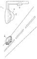
図1は、情報処理装置の概要を説明するための図である。図1を参照しながら、情報処理装置の概要について説明する。図1に示すように、情報処理システム1は、情報処理装置10と撮像装置20とを備える。また、図1を参照すると、道路平面上に車両M−1が存在する。なお、本実施形態においては、移動体として車両を例に挙げながら説明するが、移動体は車両に限定されない。すなわち、本実施形態は、車両以外の他の移動体(例えば、電車など)にも適用され得る。
[Outline of information processing equipment]
FIG. 1 is a diagram for explaining the outline of the information processing apparatus. An overview of the information processing apparatus will be described with reference to FIG. As illustrated in FIG. 1, the
撮像装置20は、魚眼レンズ210を有しており、魚眼レンズ210を透過した光に基づいて撮像を行う。このように、魚眼レンズ210を透過した光に基づいた撮像が行われる場合には、魚眼レンズ210の垂直画角が大きくなるほど、垂直方向に広範囲の映像が撮像される。また、魚眼レンズ210を透過した光に基づいた撮像が行われる場合には、魚眼レンズ210の水平画角が大きくなるほど、水平方向に広範囲の映像が撮像される。
The
ここで、魚眼レンズ210の水平画角は特に限定されないが、本実施形態においては、魚眼レンズ210の水平画角が360度である場合(撮像装置20が全方位カメラである場合)について説明する。また、魚眼レンズ210の垂直画角は特に限定されないが、例えば、垂直画角が180度以上であれば、道路平面上を走行する車両M−1がより確実に撮像装置20の撮像領域に収まる。また、図1に示した例では、撮像装置20が下向きに設置されているが、撮像装置20が設置される向きは特に限定されない。
Here, the horizontal angle of view of the
また、図1には、情報処理装置10の外部に撮像装置20が存在し、情報処理装置10と撮像装置20とが有線により接続され、情報処理装置10が、撮像装置20によって撮像された映像を受信することによって撮像映像を取得する例が示されている。しかし、撮像装置20は、情報処理装置10の内部に組み込まれていてもよい。また、例えば、情報処理装置10は、撮像装置20により記録媒体に記録された撮像映像を読み込むことにより撮像画像を取得してもよい。
In FIG. 1, an
[本実施形態の詳細]
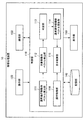
まず、本実施形態の詳細について説明する。図2は、本実施形態に係る情報処理装置10の機能構成を示すブロック図である。図2に示すように、本実施形態に係る情報処理装置10は、制御部110、操作部120、通信部130、記憶部140および表示部150を備える。
[Details of this embodiment]
First, details of the present embodiment will be described. FIG. 2 is a block diagram illustrating a functional configuration of the
操作部120は、操作者から入力される操作を受け付ける。また、操作部120は、操作者から入力される操作を制御部110に提供することができる。本実施形態では、操作部120がマウスである場合を主に想定するが(マウスを用いたクリック操作がなされる場合を主に想定するが)、操作部120はマウス以外の入力装置(例えば、タッチパネルなど)であってもよい。操作部120としてタッチパネルが用いられる場合、マウスを用いたクリック操作の代わりに、タッチパネルへのタップ操作が用いられ得る。
The
通信部130は、撮像装置20との間で通信を行うための通信インタフェースである。記憶部140は、制御部110を動作させるためのプログラムやデータを記憶することができる。また、記憶部140は、制御部110の動作の過程で必要となる各種データを一時的に記憶することもできる。表示部150は、制御部110による制御に従って、表示画面に各種情報を表示することができる。
The
なお、図2に示した例では、操作部120、通信部130、記憶部140および表示部150が、情報処理装置10の内部に設けられているが、操作部120、通信部130、記憶部140および表示部150は、情報処理装置10の外部に備えられていてもよい。制御部110は、通常進行移動体ベクトル算出部111、対象移動体ベクトル検出部112、判定部113、通常進行移動体ベクトル更新部114、表示制御部115および操作取得部116を備える。以下、制御部110が備えるこれらの各機能部の詳細について説明する。
In the example illustrated in FIG. 2, the
図3は、撮像装置20によって撮像される映像(以下、「全方位映像」とも言う。)と中心射影方式により撮像される映像(以下、「平面映像」とも言う。)との関係を示す図である。図3に示すように、魚眼レンズの球面Sから魚眼レンズの内部に入射する光は、魚眼レンズの球面Sから全方位映像撮像面Tに対して射影され、全方位映像撮像面Tにおける射影位置r(X,Y)は、全方位映像Img−10の座標XYに写る。全方位映像Img−10には、車両M−1および車両M−2が写っている。また、全方位映像Img−10における任意の領域は、中心射影方式様の平面画像Img−20に容易に変換され得る。 FIG. 3 is a diagram illustrating a relationship between a video imaged by the imaging device 20 (hereinafter also referred to as “omnidirectional video”) and a video imaged by the central projection method (hereinafter also referred to as “planar video”). It is. As shown in FIG. 3, light incident on the inside of the fisheye lens from the spherical surface S of the fisheye lens is projected from the spherical surface S of the fisheye lens onto the omnidirectional video imaging surface T, and the projected position r (X , Y) appears in the coordinates XY of the omnidirectional video Img-10. The omnidirectional video Img-10 shows the vehicle M-1 and the vehicle M-2. In addition, an arbitrary area in the omnidirectional video Img-10 can be easily converted into a planar image Img-20 like the central projection method.
図4は、表示制御部115によって表示制御される画面例を示す図である。図4に示すように、表示制御部115は、全方位映像Img−1の表示部150による表示を制御する。ここで、ユーザが車両M−2を詳細に監視したいと考えた場合を想定する。かかる場合、ユーザは、全方位映像Img−1に写る車両M−2の位置に対する選択操作(例えば、車両M−2の位置にポインタPtを合わせた後のクリック操作など)を行う。
FIG. 4 is a diagram illustrating an example of a screen whose display is controlled by the
操作取得部116が、操作部120に対して入力された選択操作を取得すると、表示制御部115は、選択操作に応じた領域を選択領域Re−1として切り出す。このとき、選択領域Re−1を示す情報(例えば、図4に示すように、選択領域Re−1を囲う枠など)が表示されてもよい。ここで、選択操作に応じた領域は限定されない。例えば、全方位映像Img−1があらかじめ複数の領域に分割されている場合、複数の領域のうち選択操作がなされた位置を含む領域が選択領域Re−1として切り出されてもよい。あるいは、選択操作がなされた位置を基準にした所定の領域(例えば、選択操作がなされた位置を中央とする所定の領域)が選択領域Re−1として切り出されてもよい。
When the
表示制御部115は、選択領域Re−1として切り出すと、選択領域Re−1を中心射影方式様の選択領域(平面映像Img−2)に変換し、中心射影方式様の選択領域(平面映像Img−2)の表示部150による表示を制御する。このように、全方位映像Img−1と平面映像Img−2との双方が表示されることによって、ユーザは、全方位映像Img−1によって全体的な監視を行い、歪みのより小さい平面映像Img−2によって全方位映像Img−1の一部の詳細な監視を行うことが可能である。
When the
ここで、情報処理装置10は、全方位映像Img−1に写る車両(例えば、車両M−1および車両M−2など)に異常が起きた場合、その異常を検出することが可能である。このとき、上記したように、あらかじめ通常進行移動体ベクトルを設定する作業はユーザにとって煩雑である。また、道路工事が行われた場合などには、一度設定した通常進行移動体ベクトルの修正作業が必要となり、この修正作業もユーザにとって煩雑である。
Here, when an abnormality occurs in a vehicle (for example, the vehicle M-1 and the vehicle M-2) shown in the omnidirectional video Img-1, the
特に、魚眼レンズ210を透過した光に基づいて撮像装置20によって撮像される場合には、撮像された映像(全方位映像Img−1)に歪みが生じるため、あらかじめ通常進行移動体ベクトルを設定する作業がさらに煩雑になる。そこで、本実施形態においては、魚眼レンズ210を透過した光に基づいて撮像がなされる場合には、その全方位映像Img−1に映る車両を監視するために必要な手間を軽減する技術を提案する。
In particular, when an image is picked up by the
まず、通常進行移動体ベクトル算出部111は、撮像装置20によって得られた過去の全方位映像に基づいて、学習により通常進行移動体ベクトルを算出する。図5は、学習によって算出された通常進行移動体ベクトルの例を示す図である。図5の全方位映像Img−11に示すように、通常進行移動体ベクトル算出部111は、過去の全方位映像に基づいて、学習により複数の通常進行移動体ベクトル(例えば、通常進行移動体ベクトルVn−1、Vn−2など)を算出することが可能である。
First, the normal traveling mobile body
なお、図5には、簡便さのために、算出される通常進行移動体ベクトルの密度が小さめに示されているが、算出される通常進行移動体ベクトルの密度は特に限定されない。例えば、通常進行移動体ベクトル算出部111は、画素ごとに通常進行移動体ベクトルを算出することも可能である。
In FIG. 5, for the sake of simplicity, the calculated density of the normally traveling moving body vector is shown to be smaller, but the calculated density of the normally traveling moving body vector is not particularly limited. For example, the normal traveling mobile body
また、学習に利用される全方位映像には制限を設けてもよい。例えば、異常が生じた車両が写っている全方位映像は、学習対象から除外されるとよい。このとき、異常が生じた車両が写っている全方位映像は、どのように学習対象から除外されてもよい。例えば、異常が生じた車両が写っている全方位映像が検出された場合に、通常進行移動体ベクトル算出部111は、初めから学習し直してもよいし、異常が生じた車両が写っている全方位映像だけを除外してもよい。
Moreover, you may provide a restriction | limiting in the omnidirectional video utilized for learning. For example, an omnidirectional video showing a vehicle in which an abnormality has occurred may be excluded from the learning target. At this time, the omnidirectional video showing the vehicle in which the abnormality has occurred may be excluded from the learning target. For example, when an omnidirectional video in which a vehicle in which an abnormality has occurred is detected, the normal traveling mobile body
また、通常進行移動体ベクトルの学習手法も特に限定されない。例えば、通常進行移動体ベクトル算出部111は、全方位映像の道路領域全体で移動ベクトルを算出し、算出した移動ベクトルを積算することによって道路領域全体(特に、車両が走行する道路領域)における通常進行移動体ベクトルを算出してもよい。あるいは、通常進行移動体ベクトル算出部111は、全方位映像から車両領域を検出し、検出した車両領域の移動ベクトルを積算することによって通常進行移動体ベクトルを算出してもよい。
Further, the learning method of the normal traveling mobile vector is not particularly limited. For example, the normal traveling vehicle
このように、通常進行移動体ベクトル算出部111による移動ベクトルの積算は、所定の領域全体(例えば、道路領域、車両領域など)に対して行われるのがよい。そうすれば、移動ベクトルが領域の中で一定になっていなくても、領域全体に対する移動ベクトルの積算によって、領域内において平均化された通常進行移動体ベクトルが算出されることになる。
As described above, the movement vector integration by the normal traveling body
通常進行移動体ベクトル算出部111による学習が終わり、撮像装置20によって新たに全方位映像が得られると、対象移動体ベクトル検出部112は、撮像装置20によって得られた全方位映像に基づいて対象移動体ベクトルを検出する。ここで、対象移動体ベクトルの検出手法は、特に限定されない。例えば、対象移動体ベクトル検出部112は、背景差分法によって全方位映像から車両領域を検出し、検出した車両領域の各画素のオプティカルフローによって(あるいは、テンプレートマッチングによって)対象移動体ベクトルを検出する。このとき、対象移動体ベクトル検出部112は、対象移動体ベクトルの方向に対する平均化などの補正処理によって、画素ごとの対象移動体ベクトルの方向のばらつきを低減してもよい。
When learning by the normal traveling body
続いて、判定部113は、通常進行移動体ベクトルと対象移動体ベクトルとの差分が閾値を超えるか否かを判定する。当該差分が閾値を超える場合には、車両に異常が生じていると判定される。このとき、閾値は、対象移動体の種類ごとにユーザによって設定されてもよいし、あらかじめ決められていてもよい。通常進行移動体ベクトルと対象移動体ベクトルとの差分には、通常進行移動体ベクトルと対象移動体ベクトルとにおける方向の差分および大きさの差分のいずれか一方だけが含まれてもよいし、双方が含まれてもよい。
Subsequently, the
また、全方位映像は連続的に撮像されているため、判定部113は、通常進行移動体ベクトルと対象移動体ベクトルとの差分が閾値を超えるか否かを判定するのに追加して、時間的な条件が満たされているか否かを判定してもよい。例えば、判定部113は、N台の車両についての当該差分が続けて(Nは2以上の任意の自然数)、閾値を超えたか否かを判定してもよい。
In addition, since the omnidirectional video is continuously captured, the
車両に生じる異常としては、「逆走」、「停止」、「低速」、「避走(物体を避けて走行すること)」などが挙げられる。「逆走」は、通常進行移動体ベクトルと対象移動体ベクトルとが逆向きである場合に検出され得る。「停止」は、対象移動体ベクトルが「0」である場合に検出され得る。「低速」は、通常進行移動体ベクトルの大きさより、対象移動体ベクトルの大きさが所定量を超えて小さい場合に検出され得る。「避走」は、通常進行移動体ベクトルと対象移動体ベクトルとにおいて方向が所定角度を超えて異なる場合に検出され得る。しかし、車両に生じる異常は、これらに限定されない。 Examples of abnormalities occurring in the vehicle include “reverse running”, “stop”, “low speed”, “evacuation (running away from an object)”, and the like. The “reverse running” can be detected when the normal traveling moving body vector and the target moving body vector are in opposite directions. “Stop” can be detected when the target moving body vector is “0”. “Low speed” can be detected when the size of the target moving body vector is smaller than a predetermined amount than the size of the normal traveling moving body vector. “Escape” can be detected when the direction of the normal moving moving body vector and the target moving body vector differ by more than a predetermined angle. However, the abnormality that occurs in the vehicle is not limited to these.
具体的な例として、図5には、車両M−1の対象移動体ベクトルVt−1が示されている。この例では、判定部113は、車両M−1の対象移動体ベクトルVt−1との間で始点同士が一致する通常進行移動体ベクトルVn−1を取得し、対象移動体ベクトルVt−1と通常進行移動体ベクトルVn−1との差分が閾値を超えると判定する(対象移動体ベクトルVt−1と通常進行移動体ベクトルVn−1とが逆向きであると判定する)。
As a specific example, FIG. 5 shows a target moving body vector Vt-1 of the vehicle M-1. In this example, the
また、図5には、車両M−2の対象移動体ベクトルVt−2が示されている。この例では、判定部113は、車両M−2の対象移動体ベクトルVt−2との間で始点同士が一致する通常進行移動体ベクトルVn−2を取得し、対象移動体ベクトルVt−2と通常進行移動体ベクトルVn−2との差分が閾値を超えていないと判定する(対象移動体ベクトルVt−1と通常進行移動体ベクトルVn−1とが同じ向きであると判定する)。
FIG. 5 shows a target moving body vector Vt-2 of the vehicle M-2. In this example, the
判定部113による判定が終わると、通常進行移動体ベクトル更新部114は、対象移動体ベクトルに基づいて通常進行移動体ベクトルを更新する。具体的には、対象移動体ベクトルVt−1を通常進行移動体ベクトルVn−1に積算し、対象移動体ベクトルVt−2を通常進行移動体ベクトルVn−2に積算する。そうすれば、異常な車両が一台だけであれば、その車両だけが異常であると判定され、同じように移動する異常な車両が続いた場合には、通常進行移動体ベクトルがそれらの異常な車両のベクトルに近づいていくため、道路を走行する車両の状況の変化に自動的に追従することが可能となる。
When the determination by the
このとき、通常進行移動体ベクトル更新部114は、対象移動体ベクトルVt−1に重みを付け、重みを付けた対象移動体ベクトルVt−1を通常進行移動体ベクトルVn−1に積算してもよい(対象移動体ベクトルVt−2に重みを付け、重みを付けた対象移動体ベクトルVt−2を通常進行移動体ベクトルVn−2に積算してもよい)。
At this time, the normal traveling mobile
上記したように、通常進行移動体ベクトルと対象移動体ベクトルとの差分が閾値を超える場合には、車両に異常が生じていると判定される。かかる場合、所定の動作が実行されてよい。例えば、表示制御部115は、通常進行移動体ベクトルと対象移動体ベクトルとの差分が閾値を超える場合、表示部150による所定の表示を制御してよい。図6は、表示制御部115によって新たに表示制御される画面例を示す図である。
As described above, when the difference between the normal traveling moving body vector and the target moving body vector exceeds the threshold, it is determined that an abnormality has occurred in the vehicle. In such a case, a predetermined operation may be performed. For example, the
図6に示すように、表示制御部115は、全方位映像Img−1の表示部150による表示を制御する。ここで、上記したように、判定部113によって、通常進行移動体ベクトルVn−1と車両M−1の対象移動体ベクトルVt−1との差分が閾値を超えると判定された場合を想定する。かかる場合、表示制御部115は、全方位映像Img−1から車両M−1の位置に応じた領域を移動体領域Re−2として切り出す。このとき、移動体領域Re−2を示す情報(例えば、図6に示すように、移動体領域Re−2を囲う枠など)が表示されてもよい。
As shown in FIG. 6, the
ここで、車両M−1の位置に応じた領域は限定されない。例えば、全方位映像Img−1があらかじめ複数の領域に分割されている場合、複数の領域のうち車両M−1の位置を含む領域が移動体領域Re−2として切り出されてもよい。あるいは、車両M−1の位置を基準にした所定の領域(例えば、車両M−1の位置を中央とする所定の領域)が移動体領域Re−2として切り出されてもよい。 Here, the area | region according to the position of the vehicle M-1 is not limited. For example, when the omnidirectional video Img-1 is divided into a plurality of regions in advance, a region including the position of the vehicle M-1 among the plurality of regions may be cut out as the moving body region Re-2. Or the predetermined area | region (For example, the predetermined area | region centering on the position of the vehicle M-1) on the basis of the position of the vehicle M-1 may be cut out as the mobile body area | region Re-2.
表示制御部115は、移動体領域Re−2として切り出すと、移動体領域Re−2を中心射影方式様の移動体領域(平面映像Img−2)に変換し、中心射影方式様の移動体領域(平面映像Img−2)の表示部150による表示を制御する。このように、全方位映像Img−1と異常な車両M−1が写る平面映像Img−2との双方が表示されることによって、ユーザは、全方位映像Img−1によって全体的な監視を行い、歪みのより小さい平面映像Img−2によって異常な車両M−1の詳細な監視を行うことが可能である。
When the
なお、表示制御部115は、中心射影方式様の移動体領域(平面映像Img−2)の表示部150による表示を制御するとともに、中心射影方式様の移動体領域に異常な車両M−1が写る旨の表示を制御してもよい。例えば、図6に示すように、表示制御部115は、中心射影方式様の移動体領域(平面映像Img−2)における異常な車両M−1が写る領域にマークFrを表示させてもよいし、単に異常な車両が検出された旨の警告メッセージを表示させてもよい。
The
[本実施形態の効果]
以上に説明したように、本実施形態によれば、通常進行移動体ベクトル算出部111と、対象移動体ベクトル検出部112と、判定部113とを備える、情報処理装置10が提供される。ここで、通常進行移動体ベクトル算出部111は、魚眼レンズ210を透過した光に基づいて撮像を行う撮像装置20によって得られた過去の撮像映像に基づいて、学習により通常進行移動体ベクトルを算出する。また、対象移動体ベクトル検出部112は、撮像装置20によって得られた対象移動体が映る撮像映像に基づいて対象移動体ベクトルを検出する。判定部113は、通常進行移動体ベクトルと対象移動体ベクトルとの差分が閾値を超えるか否かを判定する。
[Effect of this embodiment]
As described above, according to the present embodiment, the
かかる構成によれば、具体的には、通常進行移動体ベクトルが学習によって設定される。また、一度設定された通常進行移動体ベクトルの修正も学習によって行われる。したがって、魚眼レンズ210を透過した光に基づく撮像映像に映る移動体を監視するために必要な手間を軽減することが可能となる。
According to such a configuration, specifically, the normal traveling mobile body vector is set by learning. In addition, correction of the normal traveling mobile vector once set is also performed by learning. Therefore, it is possible to reduce the effort required to monitor the moving body shown in the captured image based on the light transmitted through the
なお、全方位映像のように歪んだ映像に基づいて車両の追跡処理によって車両異常を検出する場合、歪んだ映像から直接車両を追跡するのは困難であるため、歪みを補正した平面映像に対して車両異常を検出するのが一般的である。このとき、全方位映像を複数の平面映像に変換する処理が必要になるため、処理コストが増大し得る。一方、本実施形態によれば、全方位映像のように歪んだ映像から車両の追跡処理によらずに車両異常を検出するため、車両異常を検出するために全方位映像を平面映像に変換する必要はなくなり、処理コストが低減される。 In addition, when detecting a vehicle abnormality by a vehicle tracking process based on a distorted image such as an omnidirectional image, it is difficult to track the vehicle directly from the distorted image. It is common to detect vehicle anomalies. At this time, the processing cost may increase because it is necessary to convert the omnidirectional video into a plurality of planar videos. On the other hand, according to the present embodiment, in order to detect a vehicle abnormality from a distorted image such as an omnidirectional image without depending on the vehicle tracking process, the omnidirectional image is converted into a plane image in order to detect the vehicle abnormality. There is no need and processing costs are reduced.
[変形例の説明]
以上、添付図面を参照しながら本発明の好適な実施形態について詳細に説明したが、本発明はかかる例に限定されない。本発明の属する技術の分野における通常の知識を有する者であれば、特許請求の範囲に記載された技術的思想の範疇内において、各種の変更例または修正例に想到し得ることは明らかであり、これらについても、当然に本発明の技術的範囲に属するものと了解される。
[Description of modification]
The preferred embodiments of the present invention have been described in detail above with reference to the accompanying drawings, but the present invention is not limited to such examples. It is obvious that a person having ordinary knowledge in the technical field to which the present invention pertains can come up with various changes or modifications within the scope of the technical idea described in the claims. Of course, it is understood that these also belong to the technical scope of the present invention.
例えば、上記においては、中心射影方式様の選択領域(図3における平面映像Img−2)が一つだけ表示される例を説明した。しかし、中心射影方式様の選択領域は、複数表示されてもよい。このとき、例えば、通常進行移動体ベクトルと対象移動体ベクトルとの差分が閾値を超える領域が検出された場合、複数の中心射影方式様の選択領域のいずれかが、中心射影方式様の移動体領域に切り替えられてよい。そして、中心射影方式様の移動体領域に所定の表示(例えば、点滅表示など)が付されてもよい。 For example, in the above description, an example in which only one central projection method-like selection area (planar image Img-2 in FIG. 3) is displayed has been described. However, a plurality of selection areas for the central projection method may be displayed. At this time, for example, when a region in which the difference between the normal traveling moving body vector and the target moving body vector exceeds a threshold is detected, any of the plurality of central projection-like selection areas is a central-projection-like moving body. It may be switched to a region. Then, a predetermined display (for example, blinking display or the like) may be attached to the moving object region like the central projection method.
また、上記では、魚眼レンズが用いられる例を説明した。魚眼レンズを用いた場合には、上記したように、球面から平面に射影されて撮像が行われる一方、通常レンズを用いた場合には、平面から平面に射影されて撮像が行われる点で大きく異なる。通常レンズを用いる撮像方式は、中心射影方式と称され、中心射影方式によって撮像された結果には歪みがないのが特徴である。一方、魚眼レンズを用いた撮像方式は、中心射影方式以外の射影方式に相当し、具体的には、当距離射影方式、当立体角射影方式、正射影方式などに相当する。 In the above description, an example in which a fisheye lens is used has been described. When using a fish-eye lens, as described above, imaging is performed by projecting from a spherical surface to a plane, while when using a normal lens, the imaging is performed by projecting from a plane to a plane. . The image pickup method using a normal lens is called a center projection method, and is characterized in that there is no distortion in the result of image pickup by the center projection method. On the other hand, an imaging method using a fisheye lens corresponds to a projection method other than the central projection method, and specifically corresponds to a distance projection method, a solid angle projection method, an orthogonal projection method, and the like.
また、例えば、情報処理装置10の制御部110を構成する各ブロックは、例えば、CPU(Central Processing Unit)、RAM(Random Access Memory)等から構成され、記憶部140により記憶されているプログラムがCPUによりRAMに展開されて実行されることにより、その機能が実現され得る。このとき、当該プログラムを記録した、コンピュータに読み取り可能な記録媒体も提供され得る。あるいは、制御部110を構成する各ブロックは、専用のハードウェアにより構成されていてもよいし、複数のハードウェアの組み合わせにより構成されてもよい。
Further, for example, each block configuring the
1 情報処理システム
10 情報処理装置
20 撮像装置
210 魚眼レンズ
110 制御部
111 通常進行移動体ベクトル算出部
112 対象移動体ベクトル検出部
113 判定部
114 通常進行移動体ベクトル更新部
115 表示制御部
116 操作取得部
120 操作部
130 通信部
140 記憶部
150 表示部
DESCRIPTION OF
Claims (8)
前記撮像装置によって得られた対象移動体が映る撮像映像に基づいて対象移動体ベクトルを検出する対象移動体ベクトル検出部と、
前記通常進行移動体ベクトルと前記対象移動体ベクトルとの差分が閾値を超えるか否かを判定する判定部と、
を備える、情報処理装置。 A normal traveling moving body vector calculation unit that calculates a normal traveling moving body vector by learning based on past captured images obtained by an imaging device that performs imaging based on light transmitted through the fisheye lens;
A target moving body vector detection unit that detects a target moving body vector based on a captured image in which the target moving body obtained by the imaging device is reflected;
A determination unit that determines whether or not a difference between the normal traveling mobile vector and the target mobile vector exceeds a threshold;
An information processing apparatus comprising:
前記判定部によって前記差分が前記閾値を超えると判定された場合に、所定の表示を制御する表示制御部を備える、
請求項1に記載の情報処理装置。 The information processing apparatus includes:
A display control unit that controls a predetermined display when the determination unit determines that the difference exceeds the threshold;
The information processing apparatus according to claim 1.
請求項2に記載の情報処理装置。 When the determination unit determines that the difference exceeds the threshold, the display control unit cuts out an area corresponding to the position of the target moving body as a moving body area from a captured image in which the target moving body is reflected, Converting the mobile object region into a mobile object region like a central projection method, and controlling display of the mobile object region like the central projection method;
The information processing apparatus according to claim 2.
前記対象移動体が映る撮像映像からユーザによる選択操作に応じた領域を選択領域として切り出し、前記選択領域を中心射影方式様の選択領域に変換し、前記中心射影方式様の選択領域の表示を制御する表示制御部を備える、
請求項1に記載の情報処理装置。 The information processing apparatus includes:
A region corresponding to the selection operation by the user is extracted from the captured image showing the target moving body as a selection region, the selection region is converted into a central projection method-like selection region, and the display of the central projection method-like selection region is controlled. Including a display control unit,
The information processing apparatus according to claim 1.
前記対象移動体ベクトルに基づいて前記通常進行移動体ベクトルを更新する通常進行移動体ベクトル更新部を備える、
請求項1に記載の情報処理装置。 The information processing apparatus includes:
A normal progress mobile vector update unit that updates the normal progress mobile vector based on the target mobile vector;
The information processing apparatus according to claim 1.
請求項1に記載の情報処理装置。 The imaging device is an omnidirectional camera in which a horizontal angle of view of the fisheye lens is 360 degrees.
The information processing apparatus according to claim 1.
前記撮像装置によって得られた対象移動体が映る撮像映像に基づいて対象移動体ベクトルを検出することと、
前記通常進行移動体ベクトルと前記対象移動体ベクトルとの差分が閾値を超えるか否かを判定することと、
を含む、情報処理方法。 Calculating a normal traveling body vector by learning based on a past captured image obtained by an imaging device that performs imaging based on light transmitted through the fisheye lens;
Detecting a target moving body vector based on a captured image showing the target moving body obtained by the imaging device;
Determining whether a difference between the normal traveling mobile vector and the target mobile vector exceeds a threshold;
Including an information processing method.
魚眼レンズを透過した光に基づいて撮像を行う撮像装置によって得られた過去の撮像映像に基づいて、学習により通常進行移動体ベクトルを算出する通常進行移動体ベクトル算出部と、
前記撮像装置によって得られた対象移動体が映る撮像映像に基づいて対象移動体ベクトルを検出する対象移動体ベクトル検出部と、
前記通常進行移動体ベクトルと前記対象移動体ベクトルとの差分が閾値を超えるか否かを判定する判定部と、
を備える情報処理装置として機能させるためのプログラム。 Computer
A normal traveling moving body vector calculation unit that calculates a normal traveling moving body vector by learning based on past captured images obtained by an imaging device that performs imaging based on light transmitted through the fisheye lens;
A target moving body vector detection unit that detects a target moving body vector based on a captured image in which the target moving body obtained by the imaging device is reflected;
A determination unit that determines whether or not a difference between the normal traveling mobile vector and the target mobile vector exceeds a threshold;
A program for causing an information processing apparatus to function.
Priority Applications (1)
| Application Number | Priority Date | Filing Date | Title |
|---|---|---|---|
| JP2016026831A JP2017146704A (en) | 2016-02-16 | 2016-02-16 | Information processing device, information processing method and program |
Applications Claiming Priority (1)
| Application Number | Priority Date | Filing Date | Title |
|---|---|---|---|
| JP2016026831A JP2017146704A (en) | 2016-02-16 | 2016-02-16 | Information processing device, information processing method and program |
Publications (1)
| Publication Number | Publication Date |
|---|---|
| JP2017146704A true JP2017146704A (en) | 2017-08-24 |
Family
ID=59680789
Family Applications (1)
| Application Number | Title | Priority Date | Filing Date |
|---|---|---|---|
| JP2016026831A Pending JP2017146704A (en) | 2016-02-16 | 2016-02-16 | Information processing device, information processing method and program |
Country Status (1)
| Country | Link |
|---|---|
| JP (1) | JP2017146704A (en) |
Cited By (1)
| Publication number | Priority date | Publication date | Assignee | Title |
|---|---|---|---|---|
| JP2020052940A (en) * | 2018-09-28 | 2020-04-02 | 三菱電機インフォメーションシステムズ株式会社 | Method, apparatus and program for predicting motion |
Citations (7)
| Publication number | Priority date | Publication date | Assignee | Title |
|---|---|---|---|---|
| JPH06325287A (en) * | 1993-05-12 | 1994-11-25 | Omron Corp | Device for detecting traffic flow abnormality |
| JP2001216519A (en) * | 2000-02-04 | 2001-08-10 | Fujitsu Ltd | Traffic monitoring device |
| JP2001333422A (en) * | 2000-05-19 | 2001-11-30 | Matsushita Electric Ind Co Ltd | Monitoring device |
| JP2009088850A (en) * | 2007-09-28 | 2009-04-23 | Nec Corp | Moving image distribution system and moving image distributing method |
| JP2012138771A (en) * | 2010-12-27 | 2012-07-19 | Panasonic Corp | Video signal processing device and video signal processing method |
| JP2014225149A (en) * | 2013-05-16 | 2014-12-04 | 日本電信電話株式会社 | Image identification device, image identification method, and image identification program |
| JP2015226149A (en) * | 2014-05-27 | 2015-12-14 | 三菱電機株式会社 | Image processing system, imaging apparatus, and recording apparatus |
-
2016
- 2016-02-16 JP JP2016026831A patent/JP2017146704A/en active Pending
Patent Citations (7)
| Publication number | Priority date | Publication date | Assignee | Title |
|---|---|---|---|---|
| JPH06325287A (en) * | 1993-05-12 | 1994-11-25 | Omron Corp | Device for detecting traffic flow abnormality |
| JP2001216519A (en) * | 2000-02-04 | 2001-08-10 | Fujitsu Ltd | Traffic monitoring device |
| JP2001333422A (en) * | 2000-05-19 | 2001-11-30 | Matsushita Electric Ind Co Ltd | Monitoring device |
| JP2009088850A (en) * | 2007-09-28 | 2009-04-23 | Nec Corp | Moving image distribution system and moving image distributing method |
| JP2012138771A (en) * | 2010-12-27 | 2012-07-19 | Panasonic Corp | Video signal processing device and video signal processing method |
| JP2014225149A (en) * | 2013-05-16 | 2014-12-04 | 日本電信電話株式会社 | Image identification device, image identification method, and image identification program |
| JP2015226149A (en) * | 2014-05-27 | 2015-12-14 | 三菱電機株式会社 | Image processing system, imaging apparatus, and recording apparatus |
Cited By (1)
| Publication number | Priority date | Publication date | Assignee | Title |
|---|---|---|---|---|
| JP2020052940A (en) * | 2018-09-28 | 2020-04-02 | 三菱電機インフォメーションシステムズ株式会社 | Method, apparatus and program for predicting motion |
Similar Documents
| Publication | Publication Date | Title |
|---|---|---|
| JP6184271B2 (en) | Imaging management apparatus, imaging management system control method, and program | |
| JP5613041B2 (en) | Camera device, image processing system, and image processing method | |
| JP6573193B2 (en) | Determination device, determination method, and determination program | |
| US12387344B2 (en) | Object tracking apparatus, object tracking method, and program | |
| JP6335701B2 (en) | Information processing apparatus, information processing method, and program | |
| KR20090062881A (en) | Mobile robot and its moving object detection method | |
| JPWO2011108043A1 (en) | Image display device and image display method | |
| JP2019185556A (en) | Image analysis device, method, and program | |
| JP4578864B2 (en) | Automatic tracking device and automatic tracking method | |
| JP6766009B2 (en) | Monitoring equipment, monitoring methods, computer programs, and storage media | |
| JP5155110B2 (en) | Monitoring device | |
| JP6991045B2 (en) | Image processing device, control method of image processing device | |
| JP2008009849A (en) | Person tracking device | |
| JP7517312B2 (en) | Vehicle occupant travel distance measuring device, travel distance measuring program, and travel distance measuring method | |
| JP6799325B2 (en) | Image correction device, image correction method, attention point recognition device, attention point recognition method and abnormality detection system | |
| JP2020140295A (en) | Information processing equipment, information processing methods and programs | |
| JP2017146704A (en) | Information processing device, information processing method and program | |
| WO2021014873A1 (en) | Monitoring device, monitoring method, and computer readable recording medium | |
| JP7014021B2 (en) | Image processing device and monitoring area setting method | |
| JP2002190027A (en) | System and method for measuring speed by image recognition | |
| CN113108919B (en) | Human body temperature detection method, device and storage medium | |
| US20240202974A1 (en) | Information processing apparatus, information processing method, and program | |
| JP7799431B2 (en) | Information processing device, information processing method, and program | |
| JP6808398B2 (en) | Control device, imaging device, control method, and program | |
| JP2004128648A (en) | Intruding object tracking method |
Legal Events
| Date | Code | Title | Description |
|---|---|---|---|
| A621 | Written request for application examination |
Free format text: JAPANESE INTERMEDIATE CODE: A621 Effective date: 20181115 |
|
| RD03 | Notification of appointment of power of attorney |
Free format text: JAPANESE INTERMEDIATE CODE: A7423 Effective date: 20190327 |
|
| RD04 | Notification of resignation of power of attorney |
Free format text: JAPANESE INTERMEDIATE CODE: A7424 Effective date: 20190328 |
|
| A977 | Report on retrieval |
Free format text: JAPANESE INTERMEDIATE CODE: A971007 Effective date: 20191010 |
|
| A131 | Notification of reasons for refusal |
Free format text: JAPANESE INTERMEDIATE CODE: A131 Effective date: 20191203 |
|
| A02 | Decision of refusal |
Free format text: JAPANESE INTERMEDIATE CODE: A02 Effective date: 20200623 |