JP2017147787A - 多出力dc−dcコンバータ - Google Patents
多出力dc−dcコンバータ Download PDFInfo
- Publication number
- JP2017147787A JP2017147787A JP2016026003A JP2016026003A JP2017147787A JP 2017147787 A JP2017147787 A JP 2017147787A JP 2016026003 A JP2016026003 A JP 2016026003A JP 2016026003 A JP2016026003 A JP 2016026003A JP 2017147787 A JP2017147787 A JP 2017147787A
- Authority
- JP
- Japan
- Prior art keywords
- switch
- output
- turned
- inductor
- voltage
- Prior art date
- Legal status (The legal status is an assumption and is not a legal conclusion. Google has not performed a legal analysis and makes no representation as to the accuracy of the status listed.)
- Pending
Links
Images



Classifications
-
- H—ELECTRICITY
- H02—GENERATION; CONVERSION OR DISTRIBUTION OF ELECTRIC POWER
- H02M—APPARATUS FOR CONVERSION BETWEEN AC AND AC, BETWEEN AC AND DC, OR BETWEEN DC AND DC, AND FOR USE WITH MAINS OR SIMILAR POWER SUPPLY SYSTEMS; CONVERSION OF DC OR AC INPUT POWER INTO SURGE OUTPUT POWER; CONTROL OR REGULATION THEREOF
- H02M3/00—Conversion of DC power input into DC power output
- H02M3/02—Conversion of DC power input into DC power output without intermediate conversion into AC
- H02M3/04—Conversion of DC power input into DC power output without intermediate conversion into AC by static converters
- H02M3/10—Conversion of DC power input into DC power output without intermediate conversion into AC by static converters using discharge tubes with control electrode or semiconductor devices with control electrode
- H02M3/145—Conversion of DC power input into DC power output without intermediate conversion into AC by static converters using discharge tubes with control electrode or semiconductor devices with control electrode using devices of a triode or transistor type requiring continuous application of a control signal
- H02M3/155—Conversion of DC power input into DC power output without intermediate conversion into AC by static converters using discharge tubes with control electrode or semiconductor devices with control electrode using devices of a triode or transistor type requiring continuous application of a control signal using semiconductor devices only
- H02M3/156—Conversion of DC power input into DC power output without intermediate conversion into AC by static converters using discharge tubes with control electrode or semiconductor devices with control electrode using devices of a triode or transistor type requiring continuous application of a control signal using semiconductor devices only with automatic control of output voltage or current, e.g. switching regulators
- H02M3/157—Conversion of DC power input into DC power output without intermediate conversion into AC by static converters using discharge tubes with control electrode or semiconductor devices with control electrode using devices of a triode or transistor type requiring continuous application of a control signal using semiconductor devices only with automatic control of output voltage or current, e.g. switching regulators with digital control
-
- H—ELECTRICITY
- H02—GENERATION; CONVERSION OR DISTRIBUTION OF ELECTRIC POWER
- H02M—APPARATUS FOR CONVERSION BETWEEN AC AND AC, BETWEEN AC AND DC, OR BETWEEN DC AND DC, AND FOR USE WITH MAINS OR SIMILAR POWER SUPPLY SYSTEMS; CONVERSION OF DC OR AC INPUT POWER INTO SURGE OUTPUT POWER; CONTROL OR REGULATION THEREOF
- H02M3/00—Conversion of DC power input into DC power output
- H02M3/02—Conversion of DC power input into DC power output without intermediate conversion into AC
- H02M3/04—Conversion of DC power input into DC power output without intermediate conversion into AC by static converters
- H02M3/10—Conversion of DC power input into DC power output without intermediate conversion into AC by static converters using discharge tubes with control electrode or semiconductor devices with control electrode
- H02M3/145—Conversion of DC power input into DC power output without intermediate conversion into AC by static converters using discharge tubes with control electrode or semiconductor devices with control electrode using devices of a triode or transistor type requiring continuous application of a control signal
- H02M3/155—Conversion of DC power input into DC power output without intermediate conversion into AC by static converters using discharge tubes with control electrode or semiconductor devices with control electrode using devices of a triode or transistor type requiring continuous application of a control signal using semiconductor devices only
- H02M3/156—Conversion of DC power input into DC power output without intermediate conversion into AC by static converters using discharge tubes with control electrode or semiconductor devices with control electrode using devices of a triode or transistor type requiring continuous application of a control signal using semiconductor devices only with automatic control of output voltage or current, e.g. switching regulators
- H02M3/158—Conversion of DC power input into DC power output without intermediate conversion into AC by static converters using discharge tubes with control electrode or semiconductor devices with control electrode using devices of a triode or transistor type requiring continuous application of a control signal using semiconductor devices only with automatic control of output voltage or current, e.g. switching regulators including plural semiconductor devices as final control devices for a single load
-
- H—ELECTRICITY
- H02—GENERATION; CONVERSION OR DISTRIBUTION OF ELECTRIC POWER
- H02M—APPARATUS FOR CONVERSION BETWEEN AC AND AC, BETWEEN AC AND DC, OR BETWEEN DC AND DC, AND FOR USE WITH MAINS OR SIMILAR POWER SUPPLY SYSTEMS; CONVERSION OF DC OR AC INPUT POWER INTO SURGE OUTPUT POWER; CONTROL OR REGULATION THEREOF
- H02M1/00—Details of apparatus for conversion
- H02M1/08—Circuits specially adapted for the generation of control voltages for semiconductor devices incorporated in static converters
-
- H—ELECTRICITY
- H02—GENERATION; CONVERSION OR DISTRIBUTION OF ELECTRIC POWER
- H02M—APPARATUS FOR CONVERSION BETWEEN AC AND AC, BETWEEN AC AND DC, OR BETWEEN DC AND DC, AND FOR USE WITH MAINS OR SIMILAR POWER SUPPLY SYSTEMS; CONVERSION OF DC OR AC INPUT POWER INTO SURGE OUTPUT POWER; CONTROL OR REGULATION THEREOF
- H02M1/00—Details of apparatus for conversion
- H02M1/0003—Details of control, feedback or regulation circuits
- H02M1/0009—Devices or circuits for detecting current in a converter
-
- H—ELECTRICITY
- H02—GENERATION; CONVERSION OR DISTRIBUTION OF ELECTRIC POWER
- H02M—APPARATUS FOR CONVERSION BETWEEN AC AND AC, BETWEEN AC AND DC, OR BETWEEN DC AND DC, AND FOR USE WITH MAINS OR SIMILAR POWER SUPPLY SYSTEMS; CONVERSION OF DC OR AC INPUT POWER INTO SURGE OUTPUT POWER; CONTROL OR REGULATION THEREOF
- H02M1/00—Details of apparatus for conversion
- H02M1/0083—Converters characterised by their input or output configuration
- H02M1/009—Converters characterised by their input or output configuration having two or more independently controlled outputs
Landscapes
- Engineering & Computer Science (AREA)
- Power Engineering (AREA)
- Dc-Dc Converters (AREA)
Abstract
Description
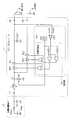
図1は、第1の実施形態に係るDC−DCコンバータを有する回路構成の一例を示す図である。第1の実施形態に係るDC−DCコンバータ1と、熱電発電素子2とからなる熱電発電装置(電源装置)の回路図が示されている。第1の実施形態に係るDC−DCコンバータ1は、入力端子11と、第1出力端子12と、第2出力端子13と、インダクタLと、第1スイッチSW1と、第2スイッチSW2と、第3スイッチSW3と、コンデンサCout1と、2つの電流検知回路ID1およびID2と、制御部14とを備える。
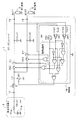
図3は、第2の実施形態に係るDC−DCコンバータを有する回路構成の一例を示す図である。第2の実施形態では、第1の実施形態における制御部14と、第2出力端子13に関連する部分が、第1の実施形態と異なる。第1の実施形態と同様な点は、説明を省略する。
図5は、第3の実施形態に係るDC−DCコンバータを有する回路構成の一例を示す図である。第1の実施形態との相違点を説明し、同様な点は説明を省略する。
図7は、第4の実施形態に係るDC−DCコンバータを有する回路構成の一例を示す図である。第3の実施形態との相違点を説明し、同様な点は説明を省略する。
11 入力端子
12 第1出力端子
13 第2出力端子
14 制御部
141 論理回路
2 熱電発電素子
3 第1負荷
4 二次電池
5 第2負荷
L インダクタ
IL インダクタ電流
LX インダクタの片側端子
Cout1、Cout2 平滑コンデンサ
OSC 発振器
CMP1、CMP2 比較器
Vout1、Vout2 出力電圧
Vref1、Vref2 参照電圧
ID1、ID2 電流検知回路
SW1、SW2、SW3、SubSW2、SubSW3 スイッチ
D、D2、D3 ダイオード
PMOS、PMOS2、PMOS3 P型MOSFET
VTEGa 開放電圧
RTEG 内部抵抗
Cin 平滑コンデンサ
Cpd ダイオードの寄生容量
Cpt PMOSの寄生容量
Vf 電圧降下
M 接続点
Claims (9)
- 入力電圧が入力される入力端子と、
出力電圧を出力する複数の出力端子と、
前記入力端子に一端が接続されたインダクタと、
オンオフ制御されることにより、前記インダクタに流れる電流を変化させる第1スイッチと、
前記インダクタと、前記複数の出力端子のうちの1つである第1出力端子との間に一端が接続され、他端がグランドに接続される第1コンデンサと、
前記インダクタと前記第1コンデンサとの間に接続された第2スイッチと、
前記第1出力端子からの第1出力電圧が予め定められた第1閾値より小さい場合に、前記第1のスイッチがオフとなったときは、前記第2スイッチをオンにするよう制御するスイッチ制御部と
を備えるDC−DCコンバータ。 - 前記インダクタと、前記複数の出力端子のうちの1つである第2出力端子との間に接続された第3スイッチ
をさらに備え、
前記スイッチ制御部は、前記第1のスイッチがオフとなったときに、前記第2のスイッチをオンにするときは、前記第3スイッチをオフに制御する
請求項1に記載のDC−DCコンバータ。 - 前記インダクタは、前記入力端子と前記第1スイッチの間に接続され、
前記第1スイッチは、一端が前記インダクタの他端に接続され、他端がグランドに接続される
請求項1または2に記載のDC−DCコンバータ。 - 前記第3スイッチと前記第2出力端子の間に接続される第2コンデンサ
をさらに備え、
前記スイッチ制御部は、前記第2出力端子からの第2出力電圧が予め定められた第2閾値より小さい場合に、前記第1のスイッチがオフとなったときに、前記第2のスイッチがオンとならないときは、前記第3スイッチをオンとする
請求項2または請求項2に従属する請求項3に記載のDC−DCコンバータ。 - 前記スイッチ制御部は、前記第1出力電圧を電源とする
請求項1ないし4のいずれか一項に記載のDC−DCコンバータ。 - 前記第1出力電圧は、前記第2出力電圧以下である
請求項4に従属する請求項5に記載のDC−DCコンバータ。 - 前記第2スイッチは、
前記インダクタから前記第1コンデンサへ向かう方向の電流は通すが、前記第1コンデンサから前記インダクタへ向かう方向の電流は通さない整流部
を備える請求項1ないし6のいずれか一項に記載のDC−DCコンバータ。 - 前記第2スイッチは、
前記整流部であり、前記インダクタに一端が接続されたダイオードと、
前記ダイオードの他端に一端が接続され、前記第1コンデンサに他端が接続されたMOSFETと、
を備える請求項7に記載のDC−DCコンバータ。 - 前記第2スイッチは、
前記第2スイッチがオンとなった後、前記第1出力電圧が予め定められた第3閾値より大きい場合に前記第1のスイッチがオフとなったときまで、オンであり続ける
請求項1ないし8のいずれか一項に記載のDC−DCコンバータ。
Priority Applications (2)
| Application Number | Priority Date | Filing Date | Title |
|---|---|---|---|
| JP2016026003A JP2017147787A (ja) | 2016-02-15 | 2016-02-15 | 多出力dc−dcコンバータ |
| US15/393,514 US10211730B2 (en) | 2016-02-15 | 2016-12-29 | DC-DC converter |
Applications Claiming Priority (1)
| Application Number | Priority Date | Filing Date | Title |
|---|---|---|---|
| JP2016026003A JP2017147787A (ja) | 2016-02-15 | 2016-02-15 | 多出力dc−dcコンバータ |
Publications (1)
| Publication Number | Publication Date |
|---|---|
| JP2017147787A true JP2017147787A (ja) | 2017-08-24 |
Family
ID=59561809
Family Applications (1)
| Application Number | Title | Priority Date | Filing Date |
|---|---|---|---|
| JP2016026003A Pending JP2017147787A (ja) | 2016-02-15 | 2016-02-15 | 多出力dc−dcコンバータ |
Country Status (2)
| Country | Link |
|---|---|
| US (1) | US10211730B2 (ja) |
| JP (1) | JP2017147787A (ja) |
Cited By (2)
| Publication number | Priority date | Publication date | Assignee | Title |
|---|---|---|---|---|
| JP2020198720A (ja) * | 2019-06-04 | 2020-12-10 | 矢崎総業株式会社 | 電源装置 |
| JP2022007685A (ja) * | 2020-06-26 | 2022-01-13 | 旭化成エレクトロニクス株式会社 | 電力供給装置 |
Families Citing this family (9)
| Publication number | Priority date | Publication date | Assignee | Title |
|---|---|---|---|---|
| JP2018029256A (ja) * | 2016-08-17 | 2018-02-22 | 株式会社東芝 | 遅延回路、発振回路、およびブーストコンバータ |
| US10819232B2 (en) * | 2017-03-14 | 2020-10-27 | Electronics And Telecommunications Research Institute | DC-DC converter and driving method thereof |
| JP2019115189A (ja) | 2017-12-25 | 2019-07-11 | 旭化成エレクトロニクス株式会社 | 電力供給装置 |
| CN108923678A (zh) * | 2018-06-28 | 2018-11-30 | 中国人民解放军空军工程大学 | 多通道机载微秒脉冲等离子体流动控制电源 |
| WO2020051790A1 (zh) * | 2018-09-12 | 2020-03-19 | Oppo广东移动通信有限公司 | 充电管理电路、终端及充电方法 |
| JP6975768B2 (ja) * | 2019-12-24 | 2021-12-01 | 本田技研工業株式会社 | 電圧変換装置 |
| BR112022024273A2 (pt) * | 2020-06-26 | 2023-01-10 | Intel Corp | Conjuntos de circuitos de múltipla saída de indutor único, mídias não trnasitórias e sistemas relacionados |
| US11569740B2 (en) * | 2021-03-17 | 2023-01-31 | Ncku Research And Development Foundation | Boost converter with fast transient response |
| US12316207B2 (en) * | 2021-12-23 | 2025-05-27 | Stmicroelectronics S.R.L. | Dual output DC-DC boost converter with reduced output leakage |
Citations (3)
| Publication number | Priority date | Publication date | Assignee | Title |
|---|---|---|---|---|
| JP2001514840A (ja) * | 1997-03-11 | 2001-09-11 | ユニットロード コーポレイション | 複合電力コンバータ |
| JP2007295736A (ja) * | 2006-04-26 | 2007-11-08 | Mitsumi Electric Co Ltd | 多出力型dc/dcコンバータ |
| JP2011061953A (ja) * | 2009-09-09 | 2011-03-24 | Fuji Electric Holdings Co Ltd | 多出力スイッチング電源装置 |
Family Cites Families (6)
| Publication number | Priority date | Publication date | Assignee | Title |
|---|---|---|---|---|
| JP2004518394A (ja) * | 2001-01-17 | 2004-06-17 | コーニンクレッカ フィリップス エレクトロニクス エヌ ヴィ | 制御された多出力dc/dcコンバータ |
| US7355368B2 (en) * | 2004-08-12 | 2008-04-08 | International Rectifier Corporation | Efficient in-rush current limiting circuit with dual gated bidirectional hemts |
| US20060176031A1 (en) * | 2005-02-04 | 2006-08-10 | Ess Technology, Inc. | Dual output switching regulator and method of operation |
| JP2006311779A (ja) * | 2005-03-31 | 2006-11-09 | Mitsumi Electric Co Ltd | 多出力型dc/dcコンバータおよびその制御方法 |
| GB2451470B (en) * | 2007-07-31 | 2011-11-23 | Wolfson Microelectronics Plc | DC-TO-DC converter |
| US20090256534A1 (en) * | 2008-04-14 | 2009-10-15 | Twisthink, L.L.C. | Power supply control method and apparatus |
-
2016
- 2016-02-15 JP JP2016026003A patent/JP2017147787A/ja active Pending
- 2016-12-29 US US15/393,514 patent/US10211730B2/en active Active
Patent Citations (3)
| Publication number | Priority date | Publication date | Assignee | Title |
|---|---|---|---|---|
| JP2001514840A (ja) * | 1997-03-11 | 2001-09-11 | ユニットロード コーポレイション | 複合電力コンバータ |
| JP2007295736A (ja) * | 2006-04-26 | 2007-11-08 | Mitsumi Electric Co Ltd | 多出力型dc/dcコンバータ |
| JP2011061953A (ja) * | 2009-09-09 | 2011-03-24 | Fuji Electric Holdings Co Ltd | 多出力スイッチング電源装置 |
Cited By (4)
| Publication number | Priority date | Publication date | Assignee | Title |
|---|---|---|---|---|
| JP2020198720A (ja) * | 2019-06-04 | 2020-12-10 | 矢崎総業株式会社 | 電源装置 |
| JP7051246B2 (ja) | 2019-06-04 | 2022-04-11 | 矢崎総業株式会社 | 電源装置 |
| JP2022007685A (ja) * | 2020-06-26 | 2022-01-13 | 旭化成エレクトロニクス株式会社 | 電力供給装置 |
| JP7566506B2 (ja) | 2020-06-26 | 2024-10-15 | 旭化成エレクトロニクス株式会社 | 電力供給装置 |
Also Published As
| Publication number | Publication date |
|---|---|
| US10211730B2 (en) | 2019-02-19 |
| US20170237346A1 (en) | 2017-08-17 |
Similar Documents
| Publication | Publication Date | Title |
|---|---|---|
| JP2017147787A (ja) | 多出力dc−dcコンバータ | |
| CN105075090B (zh) | 具有降压-升压过渡切换控制的降压-升压转换器 | |
| US9287781B2 (en) | Single inductor multiple output converter | |
| JP5381014B2 (ja) | Dc−dcコンバータ | |
| US7944191B2 (en) | Switching regulator with automatic multi mode conversion | |
| US8729873B2 (en) | DC-to-DC converter with high-side switch and low-side switch | |
| US20120091978A1 (en) | Dc-dc converter | |
| US8710822B2 (en) | Multi-state DC-DC converter having undirectional switches | |
| US9667144B2 (en) | DC-DC converter with reverse current detecting circuit | |
| US9479054B2 (en) | Buck converter with reverse current detection and pseudo ripple generation | |
| CN212572391U (zh) | 电子电路 | |
| US10056837B2 (en) | DC-DC converter and power source device | |
| JP5304173B2 (ja) | 電源電圧制御回路及びdc−dcコンバータ | |
| JP4352319B2 (ja) | 電源供給装置 | |
| US9024612B2 (en) | Buck converter having pulse skipping mode and related method of operation | |
| US9698666B2 (en) | Power supply and gate driver therein | |
| JP2014112996A (ja) | 軽負荷検出回路、スイッチングレギュレータとその制御方法 | |
| JP2013150550A (ja) | 電源電圧制御回路及び電源電圧制御方法 | |
| US7915880B2 (en) | Step-up DC-DC converter | |
| JP6234865B2 (ja) | Dc−dcコンバータ | |
| JP2009284675A (ja) | 昇圧回路および電源装置 | |
| JP2010098946A (ja) | コンバータ回路 |
Legal Events
| Date | Code | Title | Description |
|---|---|---|---|
| A621 | Written request for application examination |
Free format text: JAPANESE INTERMEDIATE CODE: A621 Effective date: 20180227 |
|
| A131 | Notification of reasons for refusal |
Free format text: JAPANESE INTERMEDIATE CODE: A131 Effective date: 20181221 |
|
| A977 | Report on retrieval |
Free format text: JAPANESE INTERMEDIATE CODE: A971007 Effective date: 20181227 |
|
| A521 | Request for written amendment filed |
Free format text: JAPANESE INTERMEDIATE CODE: A523 Effective date: 20190219 |
|
| A02 | Decision of refusal |
Free format text: JAPANESE INTERMEDIATE CODE: A02 Effective date: 20190716 |