JP2017149169A - Control plan generation apparatus, observation system, and control plan correction method - Google Patents
Control plan generation apparatus, observation system, and control plan correction method Download PDFInfo
- Publication number
- JP2017149169A JP2017149169A JP2016030658A JP2016030658A JP2017149169A JP 2017149169 A JP2017149169 A JP 2017149169A JP 2016030658 A JP2016030658 A JP 2016030658A JP 2016030658 A JP2016030658 A JP 2016030658A JP 2017149169 A JP2017149169 A JP 2017149169A
- Authority
- JP
- Japan
- Prior art keywords
- observation
- control plan
- period
- operation state
- correction
- Prior art date
- Legal status (The legal status is an assumption and is not a legal conclusion. Google has not performed a legal analysis and makes no representation as to the accuracy of the status listed.)
- Granted
Links
Images








Landscapes
- Radar Systems Or Details Thereof (AREA)
Abstract
【課題】制御計画による観測が中断されても効率的な観測を再開することを可能とする制御計画生成装置を提供する。【解決手段】制御計画生成装置2は、観測期間内に設定された複数の指定時間帯に対してそれぞれセンサ機器の複数の観測動作状態を定める初期の制御計画が記憶されている制御計画格納部15と、センサ機器が初期の制御計画による観測を実行できない割り込み期間が生じたときに修正計画を生成する修正計画生成部23と、その修正計画をセンサ機器に供給するセンサインタフェース部(センサI/F部)26とを備える。修正計画生成部23は、センサ機器で選択可能な観測動作状態の複数候補の各候補で指定される観測角度が、初期の制御計画における割り込み期間経過後の観測動作状態で指定される観測角度に近くなるほど高くなる評価値を算出し、当該評価値に基づいて前記複数候補の中から一の観測動作状態を選択することにより修正計画を生成する。【選択図】図1Provided is a control plan generation device capable of restarting efficient observation even when observation by a control plan is interrupted. A control plan generator 2 stores an initial control plan that defines a plurality of observation operation states of sensor devices for a plurality of designated time zones set within an observation period. 15, a correction plan generation unit 23 that generates a correction plan when an interruption period during which the sensor device cannot perform observation based on the initial control plan occurs, and a sensor interface unit (sensor I / I) that supplies the correction plan to the sensor device F section) 26. The correction plan generation unit 23 sets the observation angle specified by each candidate of the plurality of observation operation states that can be selected by the sensor device to the observation angle specified by the observation operation state after the interruption period in the initial control plan. An evaluation value that increases with increasing proximity is calculated, and a correction plan is generated by selecting one observation operation state from the plurality of candidates based on the evaluation value. [Selection] Figure 1
Description
本発明は、複数の観測対象を観測するセンサ機器で使用される制御計画を自動生成する技術に関する。 The present invention relates to a technique for automatically generating a control plan used in a sensor device that observes a plurality of observation objects.
近年、地球の周りを、人工衛星及びスペースデブリ(宇宙ゴミ)などの無数の飛翔物体が高速で周回している。この種の飛翔物体は、RSO(Resident Space Object)と呼ばれており、RSOの軌道は、惑星の重力による摂動などの要因により時々刻々と変化していく。RSOは、たとえば、現在運用中の人工衛星または宇宙ステーションに衝突した場合には甚大な被害を及ぼすため、各国の宇宙開発の脅威となっている。この脅威に対処するために、レーダ装置及び光学望遠鏡などのセンサ機器を用いてRSOを監視することを目的とするSSA(Space Situational Awareness:宇宙状況監視)という概念の重要性が高まっている。 In recent years, countless flying objects such as artificial satellites and space debris (space debris) orbit around the earth at high speed. This type of flying object is called RSO (Resident Space Object), and the orbit of RSO changes from moment to moment due to factors such as perturbation due to the gravity of the planet. RSO is a threat to space development in each country because it causes enormous damage when it collides with a satellite or space station currently in operation. In order to cope with this threat, the concept of SSA (Space Situation Awareness), which aims to monitor RSO using a sensor device such as a radar device and an optical telescope, is becoming more important.
SSAに関する従来技術は、たとえば、特許文献1(特開2002−220099号公報)に開示されている。特許文献1には、固定された観測方向(たとえば、子午線)の設定範囲を通過する飛翔物体を光学装置を用いて常時監視する技術が開示されている。
The prior art regarding SSA is disclosed, for example, in Patent Document 1 (Japanese Patent Laid-Open No. 2002-222009).
SSAでは、限られた観測期間内に、限られたセンサ資源(たとえば、1台のレーダ装置)を用いて出来るだけ多数のRSOを監視しなければならない場合がある。このような場合には、或るセンサ資源が「いつ」,「どの方位を」観測するのかに関して、センサ資源の効率的な制御計画を作成することが望ましい。 In SSA, it is sometimes necessary to monitor as many RSOs as possible using limited sensor resources (for example, one radar device) within a limited observation period. In such a case, it is desirable to create an efficient control plan for sensor resources with respect to when and when a certain sensor resource is observed.
しかしながら、そのような効率的な制御計画が作成されていたとしても、センサ資源は、予定されていた観測期間中に、当該制御計画で予定されていない予期せぬ観測(たとえば、緊急度の高い観測)を強いられることで、当該制御計画による観測を開始することができない、もしくは、当該制御計画による観測を中断せざるを得ない場合がある。あるいは、センサ資源が突発的に故障した場合にも、そのセンサ資源が正常な状態に戻るまでの間は、当該制御計画による観測を開始することができず、もしくは、当該制御計画による観測を中断せざるを得ない。これらの場合、その予期せぬ観測が完了した後に、もしくはセンサ資源が正常な状態に戻った後に、当該制御計画による観測を実行しようとしても、当該制御計画は、もはや効率的な制御計画であるとは限らないという課題がある。 However, even if such an efficient control plan has been developed, sensor resources may not be expected during the scheduled observation period for unexpected observations (eg, For example, the observation by the control plan may not be started or the observation by the control plan may be interrupted. Alternatively, even if a sensor resource suddenly fails, observation by the control plan cannot be started until the sensor resource returns to a normal state, or observation by the control plan is suspended. I have to. In these cases, the control plan is no longer an efficient control plan even if an attempt is made to perform the observation by the control plan after the unexpected observation is completed or the sensor resource returns to a normal state. There is a problem that is not always.
上記に鑑みて本発明の目的は、予定されていた観測期間中に制御計画による観測を実行することができない期間が生じても、その期間の経過後に効率的な観測を実行させることができる制御計画生成装置、観測システム及び制御計画修正方法を提供することである。 In view of the above, an object of the present invention is to provide a control capable of performing efficient observation after the lapse of the period even if a period during which observation by the control plan cannot be performed occurs during the scheduled observation period. A plan generation device, an observation system, and a control plan correction method are provided.
本発明の一態様による制御計画生成装置は、観測期間内に設定された複数の指定時間帯に対してそれぞれセンサ機器の複数の観測動作状態を定める初期の制御計画が記憶されている制御計画格納部と、前記センサ機器が前記初期の制御計画による観測を実行することができない割り込み期間が生じたとき、前記複数の指定時間帯のうちの前記割り込み期間経過後の各指定時間帯ごとに、前記センサ機器で選択可能な観測動作状態の複数候補の中から一の観測動作状態を選択することにより修正計画を生成する修正計画生成部と、前記修正計画のデータを前記センサ機器に供給するセンサインタフェース部とを備え、前記修正計画生成部は、前記複数候補の各候補で指定される観測角度が、前記初期の制御計画で定められた当該複数の観測動作状態のうちの前記割り込み期間経過後の観測動作状態で指定される観測角度に近くなるほど高くなる評価値を算出し、前記評価値に基づいて前記複数候補の中から一の観測動作状態を選択することにより前記修正計画を生成することを特徴とする。 A control plan generation apparatus according to an aspect of the present invention stores a control plan storing an initial control plan that defines a plurality of observation operation states of sensor devices for a plurality of specified time zones set within an observation period. And when the interrupt period during which the sensor device cannot perform observation according to the initial control plan occurs, for each specified time period after the interruption period of the plurality of specified time periods, A correction plan generation unit that generates a correction plan by selecting one observation operation state from a plurality of observation operation state candidates that can be selected by the sensor device, and a sensor interface that supplies the correction plan data to the sensor device A plurality of observation operations in which an observation angle specified by each of the plurality of candidates is determined by the initial control plan. An evaluation value that becomes higher as the observation angle specified in the observation operation state after the interruption period elapses is closer, and selects one observation operation state from the plurality of candidates based on the evaluation value Thus, the correction plan is generated.
本発明の他の態様による観測システムは、前記制御計画生成装置と、前記制御計画生成装置で生成された修正計画に従って複数の観測対象を観測するセンサ機器とを備えることを特徴とする。 An observation system according to another aspect of the present invention includes the control plan generation device and a sensor device that observes a plurality of observation targets according to a correction plan generated by the control plan generation device.
本発明の更に他の態様による制御計画修正方法は、観測期間内に設定された複数の指定時間帯に対してそれぞれセンサ機器の複数の観測動作状態を定める初期の制御計画を修正するための制御計画修正方法であって、前記センサ機器が前記初期の制御計画による観測を実行することができない割り込み期間が生じたとき、前記複数の指定時間帯のうちの前記割り込み期間経過後の各指定時間帯ごとに、前記センサ機器で選択可能な観測動作状態の複数候補の各候補で指定される観測角度が、前記初期の制御計画で定められた当該複数の観測動作状態のうちの前記割り込み期間経過後の観測動作状態で指定される観測角度に近くなるほど高くなる評価値を算出するステップと、前記割り込み期間経過後の当該各指定時間帯ごとに、前記評価値に基づいて前記複数候補の中から一の観測動作状態を選択することにより修正計画を生成するステップと、前記修正計画のデータを前記センサ機器に供給するステップとを備えることを特徴とする。 A control plan correction method according to still another aspect of the present invention is a control for correcting an initial control plan that defines a plurality of observation operation states of sensor devices for a plurality of designated time zones set within an observation period. In the plan correction method, when an interrupt period during which the sensor device cannot perform observation according to the initial control plan occurs, each specified time period after the interruption period has elapsed among the plurality of specified time periods For each of the plurality of observation operation state candidates that can be selected by the sensor device, after the interruption period has elapsed among the plurality of observation operation states determined in the initial control plan. Calculating an evaluation value that becomes higher as the observation angle specified in the observation operation state becomes closer to the evaluation value for each specified time period after the interruption period has elapsed. Generating a revised plan by selecting an observation operation state from the plurality candidates Zui, characterized in that it comprises a step of supplying data of the revised plan to the sensor device.
本発明によれば、観測期間中に初期の制御計画による観測を実行することができない割り込み期間が生じても、その割り込み期間経過後にセンサ機器に効率的な観測を実行させる修正計画を生成することができる。 According to the present invention, even if an interrupt period during which an observation based on the initial control plan cannot be performed occurs during the observation period, a correction plan is generated that causes the sensor device to perform an efficient observation after the interrupt period has elapsed. Can do.
以下、図面を参照しつつ、本発明に係る種々の実施の形態について詳細に説明する。なお、図面全体において同一符号を付された構成要素は、同一構成及び同一機能を有するものとする。 Hereinafter, various embodiments according to the present invention will be described in detail with reference to the drawings. In addition, the component to which the same code | symbol was attached | subjected in the whole drawing shall have the same structure and the same function.
実施の形態1.
図1は、本発明に係る実施の形態1の制御システム1の概略構成を示すブロック図である。図1に示されるように、この制御システム1は、制御計画生成装置2及び制御計画実行部3を備えて構成されている。制御計画生成装置2は、所定観測期間T(たとえば、数時間〜24時間)内に観測可能な多数のRSO(Resident Space Object)を効率良く観測するために必要な制御計画を生成する機能を有している。RSOとしては、たとえば、地球などの惑星の周回軌道上に存在する観測対象(たとえば、現在運用されている人工衛星、現在運用されていない人工衛星及びスペースデブリ)が挙げられる。本実施の形態のRSOは、惑星の周回軌道上に存在する観測対象だけでなく、惑星に衝突するおそれのある彗星及び流星などの小天体も含むものとする。制御計画実行部3は、その制御計画に従ってRSOを観測する機能を有する。
FIG. 1 is a block diagram showing a schematic configuration of a
制御計画実行部3は、少なくとも1台の天体観測用レーダ装置などのセンサ機器を含む。図2は、その種のレーダ装置3aの一例を模式的に示す図である。このレーダ装置3aは、RSO35に対する探索機能及び追尾機能を有している。すなわち、レーダ装置3aの探索機能は、RSO35の初探知をフェンスビームFBを用いて行い、レーダ装置3aの追尾機能は、初探知以後のRSO35の追尾をトラッキングビームTBを用いて行うことができる。ここで、フェンスビームFBは、複数本の探索ビームを連ねて生成されるフェンス形状のレーダ波をいう。
The control
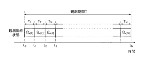
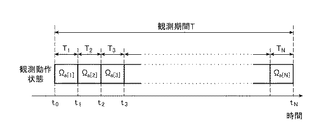
本実施の形態では、制御計画実行部3は、地上に配置されたレーダ装置からなる。このレーダ装置は、制御計画で設定された観測期間T内の各指定時間帯ごとに、当該制御計画で指定された観測動作状態で動作する。本実施の形態では、観測期間Tは、図3に示されるように、N個の指定時間帯T1,T2,…,TN(Nは正整数)に分割されているものとする。たとえば、観測期間Tの長さが24時間(=86400秒)であり、1回の指定時間帯Tnの長さが30秒である場合、2880個(=86400/30)の指定時間帯T1〜T2880を設定することができる。制御計画実行部3は、各指定時間帯Tnごとに、その制御計画で指定された観測角度(方位角θ及び仰角φ)の方向に向けて、制御計画で指定されたパターンのフェンス形状のレーダ波を送信する。本明細書では、観測角度及びフェンス形状の組み合わせをレーダ装置の「観測動作状態」と呼ぶこととする。「制御計画」は、指定時間帯T1,T2,…,TNに対してそれぞれセンサ機器の観測動作状態を定める情報をいう。
In the present embodiment, the control
制御計画生成装置2は、各指定時間帯Tnごとに、1台または複数台のセンサ機器で選択可能な観測動作状態の複数候補Ω1,Ω2,Ω3,…,ΩM(Mは正整数)の中から一の観測動作状態を選択し、この一の観測動作状態を指定時間帯Tnに割り当てることで制御計画を生成する。すなわち、図3に示されるように、指定時間帯T1,T2,…,TNに対してそれぞれ観測動作状態Ωa[1],Ωa[2],Ωa[3],…,Ωa[N]が割り当てられる。ここで、a[1]〜a[N]は、観測動作状態の候補Ω1〜ΩMの番号1〜Mの中から選択された整数である。
The control
方位角θの選択可能な値の個数をNθ、仰角φの選択可能な値の個数をNφ、フェンス形状の選択可能なパターンの個数をNfとするとき、観測動作状態の候補数は、Nθ×Nφ×Nfとなる。たとえば、方位角θが0°〜360°の範囲内で1°刻みで360個の数値をとり得、仰角φが0°〜90°の範囲内で1°刻みで90個の数値をとり得、フェンス形状のパターン数が3つである場合、観測動作状態の候補数は、97200(=360×90×3)個となる。ただし、レーダ装置に限界駆動速度の制約が存在する場合には、指定時間帯Tnの間に駆動可能な角度が存在するため方位角θは限定される。たとえば、方位角θにおける限界駆動速度が毎秒1°であり、1回当たりの指定時間帯Tnが30秒である場合には、1回前の指定時間帯Tn−1における最適方位角±30°の範囲(−30°〜+30°の範囲)が、現在の指定時間帯Tnにおける方位角θの候補範囲である。 When the number of selectable values of azimuth angle θ is N θ , the number of selectable values of elevation angle φ is N φ , and the number of selectable fence shapes is N f , the number of observation operation state candidates is , N θ × N φ × N f . For example, 360 numerical values can be obtained in increments of 1 ° within an azimuth angle θ range of 0 ° to 360 °, and 90 numerical values can be obtained in increments of 1 ° within an elevation angle φ of 0 ° to 90 °. When there are three fence-shaped patterns, the number of observation operation state candidates is 97200 (= 360 × 90 × 3). However, when the limit of the limit driving speed exists in the radar apparatus, the azimuth angle θ is limited because there is an angle that can be driven during the designated time period T n . For example, when the limit driving speed at the azimuth angle θ is 1 ° per second and the designated time zone T n per time is 30 seconds, the optimum azimuth angle ± at the designated time zone T n−1 one time before is given. range of 30 ° (the range of -30 ° ~ + 30 °) is a candidate range of azimuth angle θ in the current time zone specification T n.
図4は、制御計画で定められる方位角θの数値例を示すグラフである。図4に示されるように、制御計画実行部3を構成する2台のレーダ装置3a,3bの各々に対して、30秒の指定時間帯Tnごとに方位角θの数値が定められている。なお、本発明の観測動作状態は、方位角θ、仰角φ及びフェンス形状の組み合わせに限定されるものではない。
FIG. 4 is a graph showing a numerical example of the azimuth angle θ determined in the control plan. As shown in FIG. 4, two
次に、制御計画生成装置2の構成について詳細に説明する。図1に示されるように制御計画生成装置2は、制御計画の生成に必要な各種データが格納されているデータ格納部10と、観測期間Tにおける各RSOの予測位置を示す座標情報を算出する位置演算部21と、その座標情報を用いて制御計画を生成する制御計画生成部22と、その座標情報及び制御計画を用いて、修正された制御計画(以下「修正計画」という。)を生成する修正計画生成部23と、データ編集処理部24と、インタフェース部(I/F部)25と、センサインタフェース部(センサI/F部)26とを備えて構成されている。
Next, the configuration of the control
データ格納部10は、軌道情報格納部11、観測可能距離データ格納部12、優先度データ格納部13、センサ諸元格納部14及び制御計画格納部15を有する。軌道情報格納部11には、各RSOの軌道情報とこの軌道情報の最終更新時間とが格納されている。軌道情報としては、たとえば、TLE(Two Line Element:2行軌道要素)形式と呼ばれるフォーマットで管理されたTLE軌道情報を使用することができる。TLE軌道情報では、観測対象となる飛翔物体の、地心座標系におけるケプラー軌道要素がテキスト形式で記述される。この種のTLE軌道情報は、たとえば、米国の宇宙監視網(SSN:Space Surveillance Network)により提供されている。
The
観測可能距離データ格納部12には、各種RSOの観測可能距離を示すデータが格納されている。観測可能距離としては、たとえば、RSOのRCS(Radar Cross Section:レーダ反射断面積)を基に算出された値を使用すればよい。RCSについては、たとえば、RSOを観測する施設または機関からRCSのデータを取得することができる。優先度データ格納部13には、ユーザによる操作入力を基に数値化された優先度データが格納されている。優先度データの詳細については後述する。
The observable distance
また、センサ諸元格納部14には、制御計画実行部3を構成するレーダ装置の性能諸元を示す諸元データが格納されている。諸元データは、たとえば、レーダ装置の設置緯度及び設置経度、最大処理距離、及びフェンスビームのフェンス形状パターンを示すデータを含む。制御計画格納部15には、制御計画生成部22で生成された制御計画のデータが格納されている。
The sensor
なお、必ずしもデータ格納部10の全部が制御計画生成装置2に組み込まれている必要はない。たとえば、LAN(Local Area Network)または広域通信網などの電気通信網を介して制御計画生成装置2と接続された外部のデータ記録装置内にデータ格納部10の一部が構成されてもよい。また、軌道情報格納部11、観測可能距離データ格納部12、優先度データ格納部13、センサ諸元格納部14及び制御計画格納部15は、必ずしも1台のデータ記録装置内に構成される必要はなく、複数台のデータ記録装置に分散して構成されてもよい。
Note that the entire
位置演算部21は、データ格納部10にアクセスしてセンサ諸元格納部14からセンサ機器の性能諸元を示す諸元データを取得し、軌道情報格納部11からRSOの軌道情報を取得する。位置演算部21は、その諸元データと軌道情報とを用いて観測期間Tにおける各RSOの予測位置を示す座標情報を算出し、各RSOの座標情報が記述されたリスト(以下「RSOリスト」ともいう。)を生成する。言い換えれば、位置演算部21は、各RSOの軌道情報を、制御計画生成部22及び修正計画生成部23が容易に利用することができる別形式の軌道情報(RSOリスト)へ変換している。RSOリストのデータLDは、制御計画生成部22及び修正計画生成部23に供給される。
The
制御計画生成部22は、図1に示されるように指標算出部30と動作状態決定部31とを有する。指標算出部30は、データ格納部10内の各種データとRSOリストとに基づいて、指定時間帯Tnごとに各RSOの観測可能な度合いを示す指標を算出する。この指標の詳細については後述する。動作状態決定部31は、この指標に基づいて、各指定時間帯Tnごとに、センサ機器で選択可能な観測動作状態の複数候補Ω1,Ω2,Ω3,…,ΩMの中から一の観測動作状態を決定することにより制御計画(以下「初期の制御計画」ともいう。)を生成する。この初期の制御計画を示すデータは、センサI/F部26を介して制御計画実行部3に供給される。制御計画実行部3は、予定されている観測期間T内に、その初期の制御計画に従って多数のRSOを効率良く観測することができる。
As shown in FIG. 1, the control
また、修正計画生成部23は、観測期間T内に、制御計画実行部3が初期の制御計画による観測を実行することができない割り込み期間が生じたときに、制御計画実行部3からの計画修正要求に応じて動作する。図1に示されるように、修正計画生成部23は、指標算出部32と動作状態決定部33とを有する。指標算出部32は、その計画修正要求に応じて、データ格納部10内の各種データとRSOリストとに基づいて、割り込み期間経過後の各指定時間帯Tiごとに、評価値算出用の各種指標値を算出する。各種指標値の詳細については後述する。動作状態決定部33は、この各種指標値に基づいて、各指定時間帯Tiごとに、観測動作状態の複数候補Ω1,Ω2,Ω3,…,ΩMの中から一の観測動作状態を選択することにより修正計画を生成する。この修正計画を示すデータは、センサI/F部26を介して制御計画実行部3に供給される。制御計画実行部3は、その修正計画に従って多数のRSOの効率の良い観測を実行することができる。
Further, the correction
また、制御計画生成装置2は、図1に示されるように、I/F部25を介してディスプレイ装置4及び操作入力部5と接続されている。ディスプレイ装置4は、たとえば、液晶表示パネルまたは有機EL表示パネルなどの画像表示デバイスである。また、操作入力部5は、ユーザによる操作入力を受け付ける入力ボタン及び入力キーを有している。データ編集処理部24は、I/F部25を介してユーザによる操作入力を受け付け、この操作入力に応じてデータ格納部10に格納されている各種データの設定値を編集可能とする機能を有する。具体的には、データ編集処理部24は、ディスプレイ装置4にデータ編集用画面を表示させることができる。ユーザは、そのデータ編集用画面を視認しつつ操作入力部5を操作してデータ編集処理部24に情報を入力することが可能である。また、ユーザは、操作入力部5を操作して制御計画の生成要求を位置演算部21に入力することもできる。
Further, as shown in FIG. 1, the control
次に、上記制御計画生成装置2の動作について説明する。図5は、位置演算部21により実行される位置演算処理の手順の一例を概略的に示すフローチャートである。
Next, the operation of the control
図5を参照すると、位置演算部21は、RSOリストを初期化し(ステップST1)、次いで、センサ諸元格納部14からレーダ装置の性能諸元(たとえば、レーダ装置の設置緯度及び設置経度、並びに最大処理距離)を示す諸元データを取得する(ステップST2)。そして、位置演算部21は、RSOを1つ選択する(ステップST3)。具体的には、RSO識別番号ID1を指定して当該RSOを選択することができる。また、位置演算部21は、軌道情報格納部11から当該RSOの軌道情報を取得する(ステップST4)。
Referring to FIG. 5, the
次に、位置演算部21は、レーザ装置の諸元データ及び当該RSOの軌道情報に基づき、ユーザによって指定された観測期間T内のRSOの予測位置を示す座標情報を算出し(ステップST5)、この座標情報をRSOリストに追加する(ステップST6)。具体的には、位置演算部21は、当該レーダ装置を中心とし且つ最大処理距離を半径とする半球内に当該RSOが存在する時刻を、或る時間単位(たとえば、0.5秒〜1.0秒)で算出するとともに、各時刻におけるRSOの存在位置を算出することができる。
Next, the
次に、位置演算部21は、全てのRSOについて座標情報が算出されたか否かを判定する(ステップST7)。全てのRSOについて座標情報が算出されていないとき(ステップST7のNO)、位置演算部21は、未だ選択されていない新たなRSOを1つ選択する(ステップST8)。具体的には、RSO識別番号IDk(k=2)を指定することで当該新たなRSOを選択することができる。その後、ステップST4〜ST7の処理が実行される。全てのRSOについて座標情報が算出されたときは(ステップST7のYES)、位置演算部21は、RSOリストを制御計画生成部22または修正計画生成部23に出力し(ステップST9)、位置演算処理を終了させる。
Next, the
図6は、RSOリストの内容の一例を示す図である。図6に示されるRSOリストにおいては、RSO識別番号IDk(kは、1〜Kのうちの任意整数:Kは正整数)ごとに、ユーザにより指定された観測期間Tにおける時刻τ(k,1),τ(k,2),…と、これら時刻τ(k,1),τ(k,2),…にそれぞれ対応する当該RSOの予測位置を示す位置座標Pos(k,1),Pos(k,2),…とが記述されている。 FIG. 6 is a diagram illustrating an example of the contents of the RSO list. In the RSO list shown in FIG. 6, for each RSO identification number ID k (k is an arbitrary integer from 1 to K: K is a positive integer), the time τ (k, k,) in the observation period T specified by the user. 1), τ (k, 2),..., And position coordinates Pos (k, 1), which indicate predicted positions of the RSO corresponding to these times τ (k, 1), τ (k, 2),. Pos (k, 2), ... is described.
次に、図7を参照しつつ、制御計画生成部22の動作について説明する。図7は、制御計画生成処理の手順の一例を概略的に示すフローチャートである。制御計画生成部22は、操作入力部5からI/F部25を介して制御計画の生成要求が入力されると、この生成要求に応じて制御計画生成処理を開始する。
Next, the operation of the
図7を参照すると、先ず、指標算出部30は、制御計画を初期化する(ステップST11)。このとき、後述する全ての全体評価値も初期化される。次いで、指標算出部30は、データ格納部10にアクセスして、制御計画の生成に必要な各種データを取得するとともに(ステップST12)、位置演算部21からRSOリストを取得する(ステップST13)。そして、指標算出部30は、観測期間Tにおける指定時間帯Tnを初期時間T1に設定し(ステップST14)、観測動作状態の候補Ωmを初期観測動作状態Ω1に設定し(ステップST15)、且つ、RSO識別番号IDkを1番目のRSO識別番号ID1に設定する(ステップST16)。
Referring to FIG. 7, first, the
その後、指標算出部30は、ステップST17〜ST19において、位置演算部21から取得されたRSOリストと、データ格納部10から取得された諸元データ及び観測可能距離データとに基づき、指定時間帯Tkごとに、RSOの観測可能な度合いを示す指標すなわち第1〜第3の指標値を算出する。ステップST17では、指標算出部30は、RSOの探知可能個数fnum(IDk)を演算により予測する。この探知可能個数fnum(IDk)は、第1の指標値である。具体的には、方位角θ、仰角φ及びフェンス形状の組が指定されると、レーダ波によって走査されるべきフェンス範囲が確定する。指標算出部30は、RSOリスト及び各RSOの観測可能距離を参照して、観測期間T内に1秒でもフェンス範囲内に存在するRSOを探知可能と判定することができる。RSOが探知可能である場合には探知可能個数fnum(IDk)は「1」の値に設定され、RSOが探知不能である場合には探知可能個数fnum(IDk)は「0」の値に設定される。
Thereafter, the
次のステップST18では、指標算出部30は、指定時間帯TnにおけるRSOの観測可能時間ftime(IDk)を演算により予測する。具体的には、指標算出部30は、観測動作状態の候補Ωm(方位角θ、仰角φ及びフェンス形状)により、フェンスビームのフェンス形状と、レーダ波が走査可能な覆域とを確定させる。次いで、指標算出部30は、RSOリスト及び各RSOの観測可能距離を参照して、観測期間T中にRSOがフェンスビームで探知されてから覆域外に出るまでの時間をカウント(予測)することで、第2の指標値である観測可能時間ftime(IDk)を算出することができる。
In the next step ST18, the
次のステップST19では、指標算出部30は、RSOの追尾可能時間ftrack(IDk)を演算により予測する。具体的には、指標算出部30は、RSOリスト及びRSOの観測可能距離を参照して、前回の指定時間帯Tn−1から連続して追尾可能なRSOに対し、指定時間帯Tn内にこのRSOが覆域外に出るまでの時間をカウント(予測)することで、第3の指標値である追尾可能時間ftrack(IDk)を算出することができる。
In the next step ST19, the
その後、動作状態決定部31は、指定時間帯Tnにおける観測動作状態の候補Ωmを評価するRSO単位の評価値Fk(Ωm;Tn)を算出する(ステップST20)。具体的には、動作状態決定部31は、次式(1)に示されるように、上記第1〜第3の指標値fnum(IDk),ftime(IDk),ftrack(IDk)の線形結合によりRSO単位の評価値Fk(Ωm;Tn)を算出することができる。
上式(1)中、線形結合係数βは、零以上で且つ1以下の重み付け係数であり、線形結合係数γは、評価値調整用の正の定数であり、線形結合係数ωは、零以上で且つ1以下の重み付け係数である。これら重み付け係数β,γ,ωは、ユーザによる操作入力で指定された値に設定可能である。これら重み付け係数β,γ,ωを調整することでユーザが所望する制御計画を作成することができる。たとえば、重み付け係数βの値を高くすることにより、指定時間帯Tnにおいて探知可能なRSOの個数を多くする観測動作状態の評価を高いものとすることができる。また、係数γは、RSOの探知可能な個数及び評価値のオーダを揃えて、第1〜第3の指標値fnum(IDk),ftime(IDk),ftrack(IDk)の全体のバランスをとるための値である。 In the above equation (1), the linear coupling coefficient β is a weighting coefficient that is greater than or equal to zero and less than or equal to 1, the linear coupling coefficient γ is a positive constant for adjusting the evaluation value, and the linear coupling coefficient ω is greater than or equal to zero. And a weighting coefficient of 1 or less. These weighting coefficients β, γ, and ω can be set to values specified by an operation input by the user. A control plan desired by the user can be created by adjusting the weighting coefficients β, γ, and ω. For example, by increasing the value of the weighting coefficient β, it is possible to improve the evaluation of the observation operation state in which the number of RSOs that can be detected in the specified time period T n is increased. Also, the coefficient γ is obtained by aligning the number of RSO detectable numbers and the order of the evaluation values to obtain the first to third index values f num (ID k ), f time (ID k ), and f track (ID k ). It is a value for balancing the whole.
また、上式(1)中のTEは、駆動誤差係数と呼ばれる値である。駆動誤差係数TEは、前回の指定時間帯Tn−1からのレーダ装置の駆動回転角度が大きくなるほど、評価値のペナルティを大きくする値である。これは、レーダ装置が駆動することにより生じる誤差を考慮した値である。なお、1°当たりのペナルティの値は、ユーザによる操作入力で指定された値に設定可能である。 Further, TE in the above equation (1) is a value called a drive error coefficient. The drive error coefficient TE is a value that increases the penalty of the evaluation value as the drive rotation angle of the radar apparatus from the previous designated time zone T n-1 increases. This is a value considering an error caused by driving the radar apparatus. Note that the penalty value per degree can be set to a value designated by an operation input by the user.
なお、前述したように本実施の形態の評価値Fk(Ωm;Tn)は、第1〜第3の指標値fnum(IDk),ftime(IDk),ftrack(IDk)の線形結合により算出されることが好ましいが、この代わりに、第1〜第3の指標値fnum(IDk),ftime(IDk),ftrack(IDk)のうちの任意の1個の指標値または2個の指標値でRSO単位の評価値が算出されてもよい。 As described above, the evaluation value F k (Ω m ; T n ) of the present embodiment has the first to third index values f num (ID k ), f time (ID k ), and f track (ID). k ) is preferably calculated by a linear combination, but instead of any one of the first to third index values f num (ID k ), f time (ID k ), and f track (ID k ) The evaluation value in RSO units may be calculated using one index value or two index values.
更に、上式(1)中のAkは、上記第1〜第3の指標値fnum(IDk),ftime(IDk),ftrack(IDk)の全体に重み付けられる優先度係数である。この優先度係数Akは、各RSOに関して指定時間帯単位で変動する重み付け係数であり、ユーザの操作入力により設定される観測優先度と、前回観測された時間からの未観測時間長とに依存する設定値である。よって、ユーザにより高い観測優先度が設定されたRSOに対応する優先度係数Akは高い値となる。また、前回観測された時間から長時間経過しているRSOに対応する優先度係数Akも高い値となる。このようにすることにより、ユーザにより高い観測優先度が設定されたRSO、あるいは前回の観測時から長時間経過しているRSOを優先的に観測することができるように観測動作状態の候補Ωmを評価することが可能となる。なお、図1の優先度データ格納部13は、観測優先度のデータを格納している。指標算出部30は、優先度データ格納部13から観測優先度を取得して利用することができる。
Further, A k in the above equation (1) is a priority coefficient weighted to the whole of the first to third index values f num (ID k ), f time (ID k ), and f track (ID k ). It is. The priority coefficient A k is a weighting factor that varies with the specified time period units for each RSO, depends on the observation priority is set by the user's operation input, to the non-observation time length from the time the previously observed This is the setting value. Therefore, priority coefficient A k that correspond to RSO high observation priority by the user is set in a high value. Further, the priority coefficient A k is also high value corresponding to the RSO it has been a long time since the time was last observed. In this way, the observation operation state candidate Ω m so that the RSO for which a higher observation priority is set by the user or the RSO that has passed for a long time since the previous observation can be preferentially observed. Can be evaluated. Note that the priority
その後、RSO番号kが上限値Kに到達していない場合は(ステップST21のNO)、動作状態決定部31は、RSO番号kを1だけインクリメントし(ステップST22)、次いでステップST17〜ST20を実行させる。
Thereafter, when the RSO number k has not reached the upper limit K (NO in step ST21), the operation
一方、RSO番号kが上限値Kに到達している場合は(ステップST21のYES)、動作状態決定部31は、次式(2)に従って、全てのRSOに関する全体評価値F(Ωm;Tn)を算出する(ステップST23)。
その後、今回の全体評価値F(Ωm;Tn)が、指定時間帯Tnについて今まで算出された既存の全体評価値F(Ωο;Tn)(ο≠m)のいずれよりも高い場合には(ステップST24のYES)、動作状態決定部31は、指定時間帯Tnに対する観測動作状態の割り当てを更新する(ステップST25)。すなわち、今までの最も高い全体評価値F(Ωο;Tn)を有していた候補Ωοに代えて、今回の候補Ωmが指定時間帯Tnに割り当てられる。一方、今回の全体評価値F(Ωm;Tn)が今までの算出済みの既存の全体評価値よりも高く無い場合(ステップST21のNO)、動作状態決定部31は、次のステップST26に処理を移行させる。
Thereafter, the current overall evaluation value F (Ω m ; T n ) is greater than any of the existing overall evaluation values F (Ω ο ; T n ) (ο ≠ m) calculated so far for the designated time period T n. If high (YES in step ST24), operation
ステップST26では、候補Ωmの番号mが上限値Mに到達したか否かが判定される。番号mが上限値Mに到達していない場合(ステップST26のNO)、動作状態決定部31は、番号mを1だけインクリメントして次の観測動作状態を選択し(ステップST27)、ステップST16に処理を移行させる。
In step ST26, numbers m of candidate Omega m is whether the host vehicle has reached the upper limit value M is determined. When the number m has not reached the upper limit M (NO in step ST26), the operation
一方、番号mが上限値Mに到達している場合(ステップST26のYES)、動作状態決定部31は、指定時間帯Tnに割り当てられる観測動作状態を確定させ、更に、指定時間帯Tnの番号nが上限値Nに到達したか否かを判定する(ステップST28)。番号nが上限値Nに到達していない場合(ステップST28のNO)、動作状態決定部31は、番号nを1だけインクリメントして次の指定時間帯を選択し(ステップST29)、ステップST15に処理を移行させる。最終的に、番号nが上限値Nに到達したと判定された場合(ステップST28のYES)、上記制御計画生成処理は終了する。たとえば、観測期間Tが24時間(=86400秒)であり、1回分の指定時間帯が30秒である場合、2880回の指定時間帯T1〜T2880の各々について最適な観測動作状態を決定することができる。
On the other hand, if the number m reaches the upper limit value M (YES in step ST26), operation
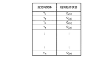
動作状態決定部31は、生成された制御計画を初期の制御計画として制御計画格納部15に格納し、生成された制御計画を示すデータを制御計画実行部3に供給する。図8は、生成された制御計画の一例を示す図である。図8の例では、指定時間帯T1,T2,T3,T4,…にそれぞれ観測動作状態Ωa[1],Ωa[2],Ωa[3],Ωa[4],…,Ωa[N]が割り当てられている。制御計画実行部3を構成する1台または複数台のレーダ装置は、指定時間帯Tnごとに制御計画で指定された観測動作状態で動作することにより多数のRSOを効率良く観測することができる。また、この観測結果を用いれば、RSOの軌道情報を最新版に更新することが可能となる。
The operation
ところで、制御計画実行部3は、制御計画生成装置2から初期の制御計画の供給を受けても、予定されていた観測期間T内に初期の制御計画による観測を実行することができない場合がある。たとえば、制御計画実行部3は、初期の制御計画で予定されていない予期せぬ観測(たとえば、緊急度の高い観測)を強いられることで、初期の制御計画による観測を開始することができない、もしくは、観測中に初期の制御計画による観測を中断せざるを得ない場合がある。あるいは、制御計画実行部3が突発的に故障した場合にも、その制御計画実行部3のセンサ機器が正常な状態に戻るまでの間は、初期の制御計画による観測を開始することができず、もしくは、初期の制御計画による観測を中断せざるを得ない。予期せぬ観測が行われる場合としては、未知のRSOが偶然探知されたためにこのRSOを緊急に観測するための観測要求があった場合、もしくは、緊急を要するロケットの打ち上げが行われたためにこのロケットを観測するための観測要求があった場合が挙げられる。そのような未知のRSOまたはロケットなどの予期せぬ観測対象は、制御計画で定められた動作制御状態の観測角度(方位角及び仰角)から大幅にずれた角度範囲に出現し得る。このような予定外の観測は、初期の制御計画を中断させる割り込み処理である。この割り込み処理が完了するまでの割り込み期間には、初期の制御計画による定常的なRSO監視業務を遂行することができない。
By the way, even if the control
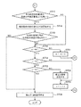
本実施の形態の修正計画生成部23は、制御計画実行部3からの計画修正要求に応じて、割り込み期間経過後の指定時間帯Ti,Ti+1,…に対して修正された制御計画(すなわち修正計画)を生成することができる。以下、図9及び図10を参照しつつ、修正計画生成部23の動作について説明する。図9及び図10は、修正計画生成処理の手順の一例を概略的に示すフローチャートである。図9のフローチャートと図10のフローチャートとは、結合子C1,C2,C3を介して相互に接続されている。
In accordance with the plan correction request from the control
制御計画実行部3は、割り込み処理が完了した後に、計画修正要求を制御計画生成装置2に向けて送信する。修正計画生成部23は、その計画修正要求をセンサI/F部26を介して受信するまで待機している(ステップST31のNO)。
The control
修正計画生成部23が計画修正要求を受信すると(ステップST31のYES)、指標算出部32は、その計画修正要求に応じて、割り込み期間経過後の観測開始予定時刻ti−1以後の制御計画を修正する期間(以下「修正期間」という。)を設定する(ステップST32)。この修正期間は、指定時間帯Ti〜TQ(Qは正整数)に設定されているものとする。
When the correction
その後、指標算出部32は、修正計画を初期化する(ステップST33)。このとき、後述する全ての全体評価値も初期化される。次いで、指標算出部32は、データ格納部10にアクセスして、修正計画の生成に必要な各種データを取得するとともに(ステップST34)、位置演算部21からRSOリストを取得する(ステップST35)。そして、指標算出部32は、観測期間Tにおける指定時間帯Tnをi番目の指定時間帯Tiに設定し(ステップST36)、観測動作状態の候補Ωmを1番目の観測動作状態Ω1に設定し(ステップST37)、且つ、RSO識別番号IDkを1番目のRSO識別番号ID1に設定する(ステップST38)。
Thereafter, the
その後、指標算出部32は、ステップST39〜ST42において、制御計画格納部15から取得された初期の制御計画と、位置演算部21から取得されたRSOリストと、データ格納部10から取得された諸元データ及び観測可能距離データとに基づき、修正期間における各指定時間帯Tnごとに、観測動作状態の候補Ωmを評価するための各種指標値を算出する。ステップST39では、指標算出部32は、第1の指標値であるRSOの探知可能個数fnum(IDk)を演算により予測する。上述した通り、RSOが探知可能である場合には探知可能個数fnum(IDk)は「1」の値に設定され、RSOが探知不能である場合には探知可能個数fnum(IDk)は「0」の値に設定される。
Thereafter, in steps ST39 to ST42, the
次のステップST40では、指標算出部32は、指定時間帯TnにおけるRSOの観測可能時間ftime(IDk)を演算により予測する。この観測可能時間ftime(IDk)は、上述した第2の指標値である。そして、次のステップST41では、指標算出部32は、RSOの追尾可能時間ftrack(IDk)を演算により予測する。この追尾可能時間ftrack(IDk)は、上述した第3の指標値である。
In the next step ST40, the
次のステップST42では、指標算出部32は、候補Ωmを初期の制御計画における修正期間内の観測動作状態と比較して、観測方向評価用の第4の指標値frs(θm)を算出する。具体的には、指標算出部32は、評価対象の候補Ωmで指定される観測角度(方位角θm)が、初期の制御計画における修正期間内の観測動作状態で指定される観測角度に近くなるほど大きくなる値を、第4の指標値frs(θm)として算出する。これにより、修正計画の観測動作状態が初期の制御計画の観測動作状態に近づくようにバイアスをかけることが可能となる。なお、ステップST42で使用される観測角度はアンテナ装置の方位角のみであるが、この代わりに、方位角と仰角との組を観測角度として使用してもよい。
In the next step ST42, the
より具体的には、指標算出部32は、初期の制御計画の観測動作状態Ωa[i],…,Ωa[Q]で指定される観測角度Θa[i],…,Θa[Q]が、その中心角Θcに関して一定の角度範囲(たとえば、Θc−30°〜Θc+30°の範囲)内に含まれているために観測角度Θa[i]〜Θa[Q]のバラツキが小さい場合と、それら観測角度Θa[i],…,Θa[Q]がその中心角Θcに関して一定の角度範囲内に含まれないために観測角度Θa[i]〜Θa[Q]のバラツキが大きい場合とに場合分けして、第4の指標値frs(θm)を算出することができる。ここで、中心角Θcは、観測角度Θa[i]〜Θa[Q]のうちの最小値と最大値との平均である。なお、中心角Θcに代えて、統計的な代表値(平均値、中央値または最頻値)が使用されてもよい。
More specifically, the
観測角度Θa[i]〜Θa[Q]のバラツキが小さい場合は、指標算出部32は、候補Ωmで指定される方位角θmと中心角Θcとの間の差分絶対値Δθ(=|Θc−θm|)が小さいほど大きくなる値に第4の指標値frs(θm)を設定することができる。
If the variation of the observation angle Θ a [i] ~Θ a [ Q] is small, the
一方、観測角度Θa[i]〜Θa[Q]のバラツキが大きい場合は、指標算出部32は、観測動作状態Ωa[i],…,Ωa[Q]の評価値F(Ωa[i];Ti),…,F(Ωa[Q];TQ)のうち最も高い評価値に対応する観測動作状態を検出し、この観測動作状態で指定される方位角ΘMAXと候補Ωmで指定される方位角θmとの間の差分絶対値(=|ΘMAX−θm|)が小さいほど大きくなる値に第4の指標値frs(θ)を設定することができる。
On the other hand, if the variation of the observation angle Θ a [i] ~Θ a [ Q] is large, the
上記ステップST42の実行後、動作状態決定部33は、指定時間帯Tnにおける観測動作状態の候補Ωmを評価するRSO単位の評価値Gk(Ωm;Tn)を算出する(ステップST43)。具体的には、動作状態決定部33は、次式(3)に示されるように、上記第1〜第4の指標値fnum(IDk),ftime(IDk),ftrack(IDk),frs(θm)の線形結合によりRSO単位の評価値Gk(Ωm;Tn)を算出することができる。
ここで、Fk(Ωm;Tn)は、上式(1)に示したように第1〜第3の指標値fnum(IDk),ftime(IDk),ftrack(IDk)の線形結合である。なお、前述したように本実施の形態の評価値Gk(Ωm;Tn)は、第1〜第4の指標値fnum(IDk),ftime(IDk),ftrack(IDk),frs(θm)の線形結合により算出されることが好ましいが、この代わりに、第1〜第3の指標値fnum(IDk),ftime(IDk),ftrack(IDk)のうちの任意の1個の指標値または2個の指標値と、第4の指標値frs(θm)との線形結合でRSO単位の評価値が算出されてもよい。 Here, F k (Ω m ; T n ) is the first to third index values f num (ID k ), f time (ID k ), f track (ID) as shown in the above equation (1). k ) linear combination. As described above, the evaluation value G k (Ω m ; T n ) of the present embodiment has the first to fourth index values f num (ID k ), f time (ID k ), and f track (ID). k ) and f rs (θ m ) are preferably calculated, but instead, the first to third index values f num (ID k ), f time (ID k ), and f track ( The evaluation value in RSO units may be calculated by linear combination of any one or two index values of ID k ) and the fourth index value f rs (θ m ).
その後、RSO番号kが上限値Kに到達していない場合は(ステップST44のNO)、動作状態決定部33は、RSO番号kを1だけインクリメントし(ステップST45)、次いでステップST39〜ST44を実行させる。
Thereafter, when the RSO number k has not reached the upper limit value K (NO in step ST44), the operation
一方、RSO番号kが上限値Kに到達している場合は(ステップST44のYES)、動作状態決定部33は、次式(4)に従って、全てのRSOに関する全体評価値G(Ωm;Tn)を算出する(ステップST46)。
その後、動作状態決定部33は、今回の全体評価値G(Ωm;Tn)が、指定時間帯Tnについて今まで算出された既存の全体評価値G(Ωο;Tn)(ο≠m)のいずれよりも高いか否かを判定する(図10のステップST47)。全体評価値G(Ωm;Tn)が既存の全体評価値G(Ωο;Tn)(ο≠m)のいずれよりも高く無い場合には(ステップST47のNO)、動作状態決定部33は、ステップST50に処理を移行させる。一方、全体評価値G(Ωm;Tn)が既存の全体評価値G(Ωο;Tn)(ο≠m)のいずれよりも高い場合には(ステップST47のYES)、動作状態決定部33は、指定時間帯Tnに対する観測動作状態の割り当てを更新する(ステップST48)。すなわち、今までの最も高い全体評価値G(Ωο;Tn)を有していた候補Ωοに代えて、今回の候補Ωmが、指定時間帯Tnに割り当てられる制御動作状態Ωb[n]となる。
Thereafter, the operation
次のステップST49では、動作状態決定部33は、初期の制御計画の制御動作状態が得られたか否かを判定する(ステップST49)。すなわち、動作状態決定部33は、指定時間帯Tnに割り当てられた観測動作状態Ωb[n]が、初期の制御計画の制御動作状態Ωa[n]と一致したか否かを判定する(ステップST49)。観測動作状態Ωb[n]が初期の制御計画の制御動作状態Ωa[n]と一致しないと判定した場合は(ステップST49のNO)、動作状態決定部33は、番号mが上限値Mに到達したか否かを判定する(ステップST50)。番号mが上限値Mに到達していない場合(ステップST50のNO)、動作状態決定部33は、番号mを1だけインクリメントして次の観測動作状態を選択し(ステップST51)、図9のステップST38に処理を移行させる。
In the next step ST49, the operation
一方、ステップST50で、番号mが上限値Mに到達していると判定された場合(ステップST50のYES)、動作状態決定部33は、更に、指定時間帯Tnの番号nが修正期間における末尾の指定時間帯TQの番号Qに到達したか否かを判定する(ステップST52)。番号nが番号Qに到達していない場合には(ステップST52のNO)、番号nを1だけインクリメントして次の指定時間帯を選択し(ステップST55)、図9のステップST37に処理を移行させる。
On the other hand, in step ST50, if the number m is determined to have reached the upper limit value M (YES in step ST50), operation
ステップST52で、番号nが番号Qに到達していると判定した場合には(ステップST52のYES)、動作状態決定部33は、更に、指定時間帯Tnの番号nが観測期間Tにおける末尾の指定時間帯TNの番号Nに到達したか否かを判定する(ステップST53)。番号nが番号Nに到達していない場合には(ステップST53のNO)、動作状態決定部33は、番号Qをより大きな値に設定することで修正期間を延長する(ステップST54)。ここで、番号Qは、番号Nよりも大きい値には設定されない。その後、動作状態決定部33は、番号nを1だけインクリメントして次の指定時間帯を選択し(ステップST55)、図9のステップST37に処理を移行させる。
In step ST52, if it is determined that the number n has reached the number Q (YES in step ST52), operation
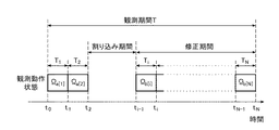
上記ステップST49で、初期の制御計画の制御動作状態が得られたと判定した場合には(ステップST49のYES)、動作状態決定部33は、この時点までに作成された修正計画を制御計画実行部3に送信する(ステップST56)。この場合、修正計画における制御動作状態Ωb[n](n<N)は、n番目の指定時間帯Tnで初期の制御計画の制御動作状態Ωa[n]に一致する。すなわち、修正計画は、指定時間帯Tnで初期の制御計画に復帰したということができる。図11Aは、この場合に出力される修正計画の一例を示す図である。図11Aの例では、指定時間帯Ti,Ti+1,…,Tq(q=n<N)に対してそれぞれ観測動作状態Ωb[i],Ωb[i+1],…,Ωb[q]が割り当てられている。図12は、この場合に時刻t2〜時刻ti−1の割り込み期間の経過後に割り当てられた観測動作状態の一例を示す図である。図12に示されるように、修正計画の制御動作状態Ωb[i]〜Ωb[q]は、時間の経過とともに次第に初期の制御計画の制御動作状態に近づいてゆき、指定時間帯Tqで修正計画の制御動作状態Ωb[q]が初期の制御計画の制御動作状態Ωa[q]と一致することとなる。
When it is determined in step ST49 that the control operation state of the initial control plan has been obtained (YES in step ST49), the operation
一方、上記ステップST53で、番号nが番号Nに到達したと判定した場合(ステップST53のYES)、動作状態決定部33は、この時点までに作成された修正計画を制御計画実行部3に送信する(ステップST56)。この場合、修正計画は、観測期間Tの最後まで初期の制御計画に復帰しなかったということができる。図11Bは、この場合に出力される修正計画の一例を示す図である。図11Bの例では、指定時間帯Ti,Ti+1,…,TNに対してそれぞれ観測動作状態Ωb[i],Ωb[i+1],…,Ωb[N]が割り当てられている。図13は、この場合に時刻t2〜時刻ti−1の割り込み期間の経過後に割り当てられた観測動作状態の一例を示す図である。
On the other hand, when it is determined in step ST53 that the number n has reached the number N (YES in step ST53), the operation
なお、上記の例では、修正計画のすべての観測動作状態の割り当てが完了した後に、この修正計画が制御計画実行部3に供給されている(ステップST56)。この代わりに、修正計画のすべての観測動作状態の割り当てが完了する前に、修正計画の各観測動作状態の割り当てが完了する度に、その各観測動作状態のデータが制御計画実行部3に供給されてもよい。
In the above example, after the assignment of all the observation operation states of the correction plan is completed, this correction plan is supplied to the control plan execution unit 3 (step ST56). Instead, before the assignment of all the observation operation states of the correction plan is completed, the data of each observation operation state is supplied to the control
上記制御計画生成装置2のハードウェア構成は、たとえば、ワークステーションまたはメインフレームなどのCPU(Central Processing Unit)内蔵のコンピュータで実現可能である。あるいは、上記制御計画生成装置2のハードウェア構成は、DSP(Digital Signal Processor)、ASIC(Application Specific Integrated Circuit)またはFPGA(Field−Programmable Gate Array)などのLSI(Large Scale Integrated circuit)により実現されてもよい。
The hardware configuration of the control
図14は、制御計画生成装置2のハードウェア構成例を概略的に示すブロック図である。図14の例では、制御計画生成装置2は、CPUを含むプロセッサ40、メモリ41、通信インタフェース部42、表示インタフェース部43及び入力インタフェース部44により構成された情報処理装置である。プロセッサ40、通信インタフェース部42、表示インタフェース部43及び入力インタフェース部44は、バス回路などの信号路45を介して相互に接続されている。
FIG. 14 is a block diagram schematically illustrating a hardware configuration example of the control
プロセッサ40は、上記した位置演算部21、制御計画生成部22、修正計画生成部23及びデータ編集処理部24の機能を実現するハードウェアである。通信インタフェース部42は、制御計画実行部3と通信して制御計画及び修正計画のデータを制御計画実行部3に出力することができる。表示インタフェース部43は、上記ディスプレイ装置4と接続され、入力インタフェース部44は、上記操作入力部5と接続されている。そして、上記データ格納部10は、メモリ41により実現可能である。メモリ41としては、たとえば、HDD(ハードディスクドライブ)またはSSD(ソリッドステートドライブ)などの不揮発性メモリを使用することができる。
The
以上に説明したように本実施の形態の制御計画生成装置2の制御計画生成部22は、センサ機器の性能諸元を示す諸元データと各観測対象の予測位置を示す座標情報とに基づいて算出された第1〜第3の指標値fnum(IDk),ftime(IDk),ftrack(IDk)を用いて、制御計画を生成することができる(図7)。よって、RSOの軌道情報を活かして、監視対象となる飛翔物体を効率良く且つ偏りなく観測することができるように制御計画を作成することが可能である。
As described above, the control
また、初期の制御計画による観測を実行することができない割り込み期間が生じた場合でも、修正計画生成部23は、その割り込み期間経過後に制御計画実行部3に効率的な観測を実行させる修正計画を生成することができる。すなわち、修正計画生成部23は、割り込み期間経過後の各指定時間帯Tnごとに、各候補Ωmで指定される観測角度が初期の制御計画の観測動作状態Ωa[n]で指定される観測角度に近くなるほど高くなる全体評価値G(Ωm;Tn)を算出することができる(図9及び図10)。よって、修正計画生成部23は、その全体評価値G(Ωm;Tn)に基づいて、時間の経過とともに初期の制御計画に近づく修正計画を生成することができる。したがって、予定されていた観測期間中に割り込み期間が生じても、初期の制御計画に復帰しやすい効率的な修正計画を制御計画実行部3に供給することができる。
Further, even when an interruption period during which the observation based on the initial control plan cannot be performed occurs, the correction
以上、図面を参照して本発明に係る実施の形態について述べたが、この実施の形態は本発明の例示であり、この実施の形態以外の様々な形態を採用することもできる。たとえば、本実施の形態の観測対象は、地球の周回軌道上に存在する飛翔物体に限らず、他の惑星または恒星の周回軌道上に存在する飛翔物体であってもよい。 As mentioned above, although embodiment which concerns on this invention was described with reference to drawings, this embodiment is an illustration of this invention, Various forms other than this embodiment can also be employ | adopted. For example, the observation target of the present embodiment is not limited to a flying object that exists in the orbit of the earth, but may be a flying object that exists in the orbit of another planet or a star.
また、上記実施の形態の観測システム1は、好適なセンサ機器としてレーダ装置を使用しているが、これに限定されるものではない。レーダ装置以外のセンサ機器(たとえば光学望遠鏡)を使用できるように制御計画生成装置2の構成を適宜変更してもよい。
Moreover, although the
なお、本発明の範囲内において、上記実施の形態の任意の構成要素の自由な組み合わせ、上記実施の形態の任意の構成要素の変形、または上記実施の形態の任意の構成要素の省略が可能である。 Within the scope of the present invention, any combination of any of the above-described embodiments, any modification of any of the above-described embodiments, or any omission of any of the above-described embodiments is possible. is there.
1 観測システム、2 制御計画生成装置、3 制御計画実行部、3a,3b レーダ装置、4 ディスプレイ装置、5 操作入力部、10 データ格納部、11 軌道情報格納部、12 観測可能距離データ格納部、13 優先度データ格納部、14 センサ諸元格納部、15 制御計画格納部、21 位置演算部、22 制御計画生成部、23 修正計画生成部、24 データ編集処理部、25 インタフェース部(I/F部)、26 センサインタフェース部(センサI/F部)、30 指標算出部、31 動作状態決定部、32 指標算出部、33 動作状態決定部、40 プロセッサ、41 メモリ、42 通信インタフェース部、43 表示インタフェース部、44 入力インタフェース部、45 信号路。
DESCRIPTION OF
Claims (10)
前記センサ機器が前記初期の制御計画による観測を実行することができない割り込み期間が生じたとき、前記複数の指定時間帯のうちの前記割り込み期間経過後の各指定時間帯ごとに、前記センサ機器で選択可能な観測動作状態の複数候補の中から一の観測動作状態を選択することにより修正計画を生成する修正計画生成部と、
前記修正計画のデータを前記センサ機器に供給するセンサインタフェース部と
を備え、
前記修正計画生成部は、前記複数候補の各候補で指定される観測角度が、前記初期の制御計画で定められた当該複数の観測動作状態のうちの前記割り込み期間経過後の観測動作状態で指定される観測角度に近くなるほど高くなる評価値を算出し、前記評価値に基づいて前記複数候補の中から一の観測動作状態を選択することにより前記修正計画を生成することを特徴とする制御計画生成装置。 A control plan storage unit that stores an initial control plan that defines a plurality of observation operation states of sensor devices for a plurality of designated time zones set within an observation period;
When there is an interrupt period in which the sensor device cannot perform observation according to the initial control plan, the sensor device is configured for each designated time period after the interruption period of the plurality of designated time periods. A correction plan generation unit that generates a correction plan by selecting one observation operation state from a plurality of selectable observation operation state candidates;
A sensor interface unit that supplies the correction plan data to the sensor device;
The correction plan generation unit is configured such that an observation angle specified by each of the plurality of candidates is an observation operation state after the interruption period of the plurality of observation operation states determined in the initial control plan. A control plan that calculates an evaluation value that increases as the observation angle approaches, and generates the correction plan by selecting one observation operation state from the plurality of candidates based on the evaluation value Generator.
前記修正計画生成部は、前記各候補で指定される当該観測角度と、前記初期の制御計画で定められた当該複数の観測動作状態のうちの前記割り込み期間経過後の観測動作状態で指定される当該観測角度との間の差分絶対値が小さくなるほど大きくなる観測方向評価用の指標値を算出し、
前記評価値は、前記観測方向評価用の指標値を含む、
ことを特徴とする制御計画生成装置。 The control plan generation device according to claim 1,
The correction plan generation unit is specified by the observation angle specified by each candidate and the observation operation state after the interruption period has elapsed among the plurality of observation operation states determined by the initial control plan. Calculate an index value for observation direction evaluation that increases as the absolute value of the difference between the observation angles decreases,
The evaluation value includes an index value for the observation direction evaluation,
A control plan generation apparatus characterized by that.
前記修正計画生成部は、前記センサ機器の性能諸元を示す諸元データ及び前記座標情報に基づき、前記割り込み期間経過後の当該各指定時間帯ごとに、前記各観測対象の観測可能な度合いを示す少なくとも1つの指標値を算出し、
前記評価値は、当該少なくとも1つの指標値を含む、
ことを特徴とする制御計画生成装置。 The control plan generation device according to claim 2, wherein trajectory information of a plurality of observation targets to be observed by the sensor device is acquired, and the predicted position of each observation target in the observation period is determined using the trajectory information. A position calculation unit for calculating the coordinate information shown,
The correction plan generation unit, based on the specification data indicating the performance specifications of the sensor device and the coordinate information, the observable degree of each observation target for each specified time zone after the interruption period has elapsed. Calculate at least one index value to indicate,
The evaluation value includes the at least one index value,
A control plan generation apparatus characterized by that.
前記制御計画生成装置で生成された修正計画に従って複数の観測対象を観測するセンサ機器と
を備えることを特徴とする観測システム。 The control plan generation device according to any one of claims 1 to 7,
An observation system comprising: a sensor device that observes a plurality of observation objects according to a correction plan generated by the control plan generation device.
前記センサ機器が前記初期の制御計画による観測を実行することができない割り込み期間が生じたとき、前記複数の指定時間帯のうちの前記割り込み期間経過後の各指定時間帯ごとに、前記センサ機器で選択可能な観測動作状態の複数候補の各候補で指定される観測角度が、前記初期の制御計画で定められた当該複数の観測動作状態のうちの前記割り込み期間経過後の観測動作状態で指定される観測角度に近くなるほど高くなる評価値を算出するステップと、
前記割り込み期間経過後の当該各指定時間帯ごとに、前記評価値に基づいて前記複数候補の中から一の観測動作状態を選択することにより修正計画を生成するステップと、
前記修正計画のデータを前記センサ機器に供給するステップと
を備えることを特徴とする制御計画修正方法。 A control plan correction method for correcting an initial control plan that defines a plurality of observation operation states of sensor devices for a plurality of designated time zones set within an observation period,
When there is an interrupt period in which the sensor device cannot perform observation according to the initial control plan, the sensor device is configured for each designated time period after the interruption period of the plurality of designated time periods. The observation angle specified by each of the plurality of selectable observation operation states is specified by the observation operation state after the interruption period of the plurality of observation operation states defined in the initial control plan. Calculating an evaluation value that increases as the observation angle approaches
Generating a correction plan by selecting one observation operation state from the plurality of candidates based on the evaluation value for each designated time period after the interruption period has elapsed; and
Supplying the data of the correction plan to the sensor device.
Priority Applications (1)
| Application Number | Priority Date | Filing Date | Title |
|---|---|---|---|
| JP2016030658A JP6469034B2 (en) | 2016-02-22 | 2016-02-22 | Control plan generation apparatus, observation system, and control plan correction method |
Applications Claiming Priority (1)
| Application Number | Priority Date | Filing Date | Title |
|---|---|---|---|
| JP2016030658A JP6469034B2 (en) | 2016-02-22 | 2016-02-22 | Control plan generation apparatus, observation system, and control plan correction method |
Publications (2)
| Publication Number | Publication Date |
|---|---|
| JP2017149169A true JP2017149169A (en) | 2017-08-31 |
| JP6469034B2 JP6469034B2 (en) | 2019-02-13 |
Family
ID=59740325
Family Applications (1)
| Application Number | Title | Priority Date | Filing Date |
|---|---|---|---|
| JP2016030658A Active JP6469034B2 (en) | 2016-02-22 | 2016-02-22 | Control plan generation apparatus, observation system, and control plan correction method |
Country Status (1)
| Country | Link |
|---|---|
| JP (1) | JP6469034B2 (en) |
Cited By (1)
| Publication number | Priority date | Publication date | Assignee | Title |
|---|---|---|---|---|
| JP2024045462A (en) * | 2019-12-06 | 2024-04-02 | キヤノン電子株式会社 | satellite tracking system |
Citations (7)
| Publication number | Priority date | Publication date | Assignee | Title |
|---|---|---|---|---|
| EP1167997A1 (en) * | 2000-06-22 | 2002-01-02 | Thales | Device for measuring pollution in space |
| JP2009179141A (en) * | 2008-01-30 | 2009-08-13 | Mitsubishi Electric Corp | Satellite observation system |
| JP2009262884A (en) * | 2008-04-29 | 2009-11-12 | Mitsubishi Electric Corp | Facility operation system having redundant system and facility operation method |
| JP2011157030A (en) * | 2010-02-03 | 2011-08-18 | Mitsubishi Electric Corp | Flying object monitoring method and monitoring device |
| JP2011183911A (en) * | 2010-03-08 | 2011-09-22 | Fujitsu Ltd | Observation plan device, observation plan method, and observation plan program |
| US20110226907A1 (en) * | 2010-03-22 | 2011-09-22 | Raytheon Company | Optimal space situational awareness system |
| JP2012144137A (en) * | 2011-01-12 | 2012-08-02 | Mitsubishi Electric Corp | Observation operation planning system |
-
2016
- 2016-02-22 JP JP2016030658A patent/JP6469034B2/en active Active
Patent Citations (8)
| Publication number | Priority date | Publication date | Assignee | Title |
|---|---|---|---|---|
| EP1167997A1 (en) * | 2000-06-22 | 2002-01-02 | Thales | Device for measuring pollution in space |
| DE60100611T2 (en) * | 2000-06-22 | 2004-06-24 | Thales | Device for measuring room pollution |
| JP2009179141A (en) * | 2008-01-30 | 2009-08-13 | Mitsubishi Electric Corp | Satellite observation system |
| JP2009262884A (en) * | 2008-04-29 | 2009-11-12 | Mitsubishi Electric Corp | Facility operation system having redundant system and facility operation method |
| JP2011157030A (en) * | 2010-02-03 | 2011-08-18 | Mitsubishi Electric Corp | Flying object monitoring method and monitoring device |
| JP2011183911A (en) * | 2010-03-08 | 2011-09-22 | Fujitsu Ltd | Observation plan device, observation plan method, and observation plan program |
| US20110226907A1 (en) * | 2010-03-22 | 2011-09-22 | Raytheon Company | Optimal space situational awareness system |
| JP2012144137A (en) * | 2011-01-12 | 2012-08-02 | Mitsubishi Electric Corp | Observation operation planning system |
Cited By (2)
| Publication number | Priority date | Publication date | Assignee | Title |
|---|---|---|---|---|
| JP2024045462A (en) * | 2019-12-06 | 2024-04-02 | キヤノン電子株式会社 | satellite tracking system |
| JP7659671B2 (en) | 2019-12-06 | 2025-04-09 | キヤノン電子株式会社 | Satellite Tracking System |
Also Published As
| Publication number | Publication date |
|---|---|
| JP6469034B2 (en) | 2019-02-13 |
Similar Documents
| Publication | Publication Date | Title |
|---|---|---|
| JP6929927B2 (en) | Methods and equipment for predicting strong convective weather | |
| TWI585442B (en) | Method and system for refining weather forecasts using point observations | |
| KR102168482B1 (en) | Method and system for refining weather forecasts using point observations | |
| US20170131716A1 (en) | Methods and apparatus to autonomously navigate a vehicle by selecting sensors from which to obtain measurements for navigation | |
| CN110770610A (en) | Self-learning immediate forecasting system for simulating, recording and predicting convective weather | |
| US11170456B2 (en) | Methods and systems for an enhanced energy grid system | |
| JP5404658B2 (en) | Observation operation planning equipment | |
| JP2009133849A (en) | Method, computer program, and data processing system for deciding estimated position in space time of rfid (radio-frequency identification) tag | |
| US20140164971A1 (en) | Hand-held personal planetarium | |
| JP5919805B2 (en) | Flying object observation data management apparatus and management method | |
| JP2019202587A (en) | Satellite observation scheduling system, and scheduling method | |
| US20100182969A1 (en) | Optimization Strategies For Resource Management And Course Of Action Analysis | |
| CN119493993B (en) | Automatic detection and recognition method and system of geological disaster monitoring equipment based on laser radar | |
| Aguilar Marsillach et al. | Spacecraft custody maintenance and maneuver detection using robotic telescopes and reachable sets | |
| JP6469034B2 (en) | Control plan generation apparatus, observation system, and control plan correction method | |
| Gehly et al. | Search-detect-track sensor allocation for geosynchronous space objects | |
| EP2558878A2 (en) | System and method for multiple target tracking | |
| CN107844576B (en) | A kind of environmentally friendly orbit generation method and system of patrolling | |
| JP6759954B2 (en) | Observation plan planning program, observation plan planning device, and observation plan planning method | |
| JP6486263B2 (en) | Control plan generation apparatus, observation system, and control plan generation method | |
| Krout et al. | Intelligent ping sequencing for multistatic sonar systems | |
| US7130805B2 (en) | Method and apparatus for generating progressive queries and models for decision support | |
| Dhingra et al. | The impact of orbit accuracy-based tasking on sensor network efficiency | |
| Herz et al. | Utilizing novel non-traditional sensor tasking approaches to enhance the space situational awareness picture maintained by the Space Surveillance Network | |
| EP3657438B1 (en) | System and method for constructing pictures of tracks of moving targets from electro-optical detections |
Legal Events
| Date | Code | Title | Description |
|---|---|---|---|
| A621 | Written request for application examination |
Free format text: JAPANESE INTERMEDIATE CODE: A621 Effective date: 20171026 |
|
| A977 | Report on retrieval |
Free format text: JAPANESE INTERMEDIATE CODE: A971007 Effective date: 20180711 |
|
| A131 | Notification of reasons for refusal |
Free format text: JAPANESE INTERMEDIATE CODE: A131 Effective date: 20180717 |
|
| A521 | Request for written amendment filed |
Free format text: JAPANESE INTERMEDIATE CODE: A523 Effective date: 20180906 |
|
| TRDD | Decision of grant or rejection written | ||
| A01 | Written decision to grant a patent or to grant a registration (utility model) |
Free format text: JAPANESE INTERMEDIATE CODE: A01 Effective date: 20181218 |
|
| A61 | First payment of annual fees (during grant procedure) |
Free format text: JAPANESE INTERMEDIATE CODE: A61 Effective date: 20190115 |
|
| R150 | Certificate of patent or registration of utility model |
Ref document number: 6469034 Country of ref document: JP Free format text: JAPANESE INTERMEDIATE CODE: R150 |
|
| R250 | Receipt of annual fees |
Free format text: JAPANESE INTERMEDIATE CODE: R250 |
|
| R250 | Receipt of annual fees |
Free format text: JAPANESE INTERMEDIATE CODE: R250 |
|
| R250 | Receipt of annual fees |
Free format text: JAPANESE INTERMEDIATE CODE: R250 |
|
| R250 | Receipt of annual fees |
Free format text: JAPANESE INTERMEDIATE CODE: R250 |
|
| R250 | Receipt of annual fees |
Free format text: JAPANESE INTERMEDIATE CODE: R250 |