JP2017149192A - Air back sensor attachment structure - Google Patents
Air back sensor attachment structure Download PDFInfo
- Publication number
- JP2017149192A JP2017149192A JP2016031158A JP2016031158A JP2017149192A JP 2017149192 A JP2017149192 A JP 2017149192A JP 2016031158 A JP2016031158 A JP 2016031158A JP 2016031158 A JP2016031158 A JP 2016031158A JP 2017149192 A JP2017149192 A JP 2017149192A
- Authority
- JP
- Japan
- Prior art keywords
- bumper beam
- airbag sensor
- beam extension
- vehicle body
- airbag
- Prior art date
- Legal status (The legal status is an assumption and is not a legal conclusion. Google has not performed a legal analysis and makes no representation as to the accuracy of the status listed.)
- Granted
Links
Images




Classifications
-
- B—PERFORMING OPERATIONS; TRANSPORTING
- B60—VEHICLES IN GENERAL
- B60R—VEHICLES, VEHICLE FITTINGS, OR VEHICLE PARTS, NOT OTHERWISE PROVIDED FOR
- B60R21/00—Arrangements or fittings on vehicles for protecting or preventing injuries to occupants or pedestrians in case of accidents or other traffic risks
- B60R21/02—Occupant safety arrangements or fittings, e.g. crash pads
- B60R21/16—Inflatable occupant restraints or confinements designed to inflate upon impact or impending impact, e.g. air bags
- B60R21/33—Arrangements for non-electric triggering of inflation
-
- B—PERFORMING OPERATIONS; TRANSPORTING
- B60—VEHICLES IN GENERAL
- B60R—VEHICLES, VEHICLE FITTINGS, OR VEHICLE PARTS, NOT OTHERWISE PROVIDED FOR
- B60R19/00—Wheel guards; Radiator guards, e.g. grilles; Obstruction removers; Fittings damping bouncing force in collisions
- B60R19/02—Bumpers, i.e. impact receiving or absorbing members for protecting vehicles or fending off blows from other vehicles or objects
- B60R19/48—Bumpers, i.e. impact receiving or absorbing members for protecting vehicles or fending off blows from other vehicles or objects combined with, or convertible into, other devices or objects, e.g. bumpers combined with road brushes, bumpers convertible into beds
-
- B—PERFORMING OPERATIONS; TRANSPORTING
- B60—VEHICLES IN GENERAL
- B60R—VEHICLES, VEHICLE FITTINGS, OR VEHICLE PARTS, NOT OTHERWISE PROVIDED FOR
- B60R11/00—Arrangements for holding or mounting articles, not otherwise provided for
-
- B—PERFORMING OPERATIONS; TRANSPORTING
- B60—VEHICLES IN GENERAL
- B60R—VEHICLES, VEHICLE FITTINGS, OR VEHICLE PARTS, NOT OTHERWISE PROVIDED FOR
- B60R11/00—Arrangements for holding or mounting articles, not otherwise provided for
- B60R11/02—Arrangements for holding or mounting articles, not otherwise provided for for radio sets, television sets, telephones, or the like; Arrangement of controls thereof
- B60R11/0264—Arrangements for holding or mounting articles, not otherwise provided for for radio sets, television sets, telephones, or the like; Arrangement of controls thereof for control means
-
- B—PERFORMING OPERATIONS; TRANSPORTING
- B60—VEHICLES IN GENERAL
- B60R—VEHICLES, VEHICLE FITTINGS, OR VEHICLE PARTS, NOT OTHERWISE PROVIDED FOR
- B60R19/00—Wheel guards; Radiator guards, e.g. grilles; Obstruction removers; Fittings damping bouncing force in collisions
- B60R19/02—Bumpers, i.e. impact receiving or absorbing members for protecting vehicles or fending off blows from other vehicles or objects
- B60R19/18—Bumpers, i.e. impact receiving or absorbing members for protecting vehicles or fending off blows from other vehicles or objects characterised by the cross-section; Means within the bumper to absorb impact
-
- B—PERFORMING OPERATIONS; TRANSPORTING
- B60—VEHICLES IN GENERAL
- B60R—VEHICLES, VEHICLE FITTINGS, OR VEHICLE PARTS, NOT OTHERWISE PROVIDED FOR
- B60R21/00—Arrangements or fittings on vehicles for protecting or preventing injuries to occupants or pedestrians in case of accidents or other traffic risks
- B60R21/01—Electrical circuits for triggering passive safety arrangements, e.g. airbags, safety belt tighteners, in case of vehicle accidents or impending vehicle accidents
- B60R21/013—Electrical circuits for triggering passive safety arrangements, e.g. airbags, safety belt tighteners, in case of vehicle accidents or impending vehicle accidents including means for detecting collisions, impending collisions or roll-over
- B60R21/0136—Electrical circuits for triggering passive safety arrangements, e.g. airbags, safety belt tighteners, in case of vehicle accidents or impending vehicle accidents including means for detecting collisions, impending collisions or roll-over responsive to actual contact with an obstacle, e.g. to vehicle deformation, bumper displacement or bumper velocity relative to the vehicle
-
- B—PERFORMING OPERATIONS; TRANSPORTING
- B60—VEHICLES IN GENERAL
- B60R—VEHICLES, VEHICLE FITTINGS, OR VEHICLE PARTS, NOT OTHERWISE PROVIDED FOR
- B60R11/00—Arrangements for holding or mounting articles, not otherwise provided for
- B60R2011/0001—Arrangements for holding or mounting articles, not otherwise provided for characterised by position
- B60R2011/004—Arrangements for holding or mounting articles, not otherwise provided for characterised by position outside the vehicle
-
- B—PERFORMING OPERATIONS; TRANSPORTING
- B60—VEHICLES IN GENERAL
- B60R—VEHICLES, VEHICLE FITTINGS, OR VEHICLE PARTS, NOT OTHERWISE PROVIDED FOR
- B60R19/00—Wheel guards; Radiator guards, e.g. grilles; Obstruction removers; Fittings damping bouncing force in collisions
- B60R19/02—Bumpers, i.e. impact receiving or absorbing members for protecting vehicles or fending off blows from other vehicles or objects
- B60R19/18—Bumpers, i.e. impact receiving or absorbing members for protecting vehicles or fending off blows from other vehicles or objects characterised by the cross-section; Means within the bumper to absorb impact
- B60R2019/1806—Structural beams therefor, e.g. shock-absorbing
- B60R2019/1813—Structural beams therefor, e.g. shock-absorbing made of metal
- B60R2019/182—Structural beams therefor, e.g. shock-absorbing made of metal of light metal, e.g. extruded
-
- B—PERFORMING OPERATIONS; TRANSPORTING
- B60—VEHICLES IN GENERAL
- B60R—VEHICLES, VEHICLE FITTINGS, OR VEHICLE PARTS, NOT OTHERWISE PROVIDED FOR
- B60R21/00—Arrangements or fittings on vehicles for protecting or preventing injuries to occupants or pedestrians in case of accidents or other traffic risks
- B60R21/01—Electrical circuits for triggering passive safety arrangements, e.g. airbags, safety belt tighteners, in case of vehicle accidents or impending vehicle accidents
- B60R2021/01006—Mounting of electrical components in vehicles
Landscapes
- Engineering & Computer Science (AREA)
- Mechanical Engineering (AREA)
- Body Structure For Vehicles (AREA)
Abstract
【課題】エアバッグセンサで衝突を精度よく早期に検知できるエアバッグセンサ取付構造を提供する。【解決手段】車体前部構造10は、左バンパビームエクステンション18の外側面38cにセンサ取付構造20が設けられる。センサ取付構造20は、左バンパビームエクステンション18の外側面38cに設けられる支持手段45と、支持手段45に取り付けられるエアバッグセンサ46とを備える。車体前方から入力する衝撃荷重F3で左バンパビームエクステンション18が圧縮される際に、左バンパビームエクステンション18の圧縮に追従して支持手段45が車体後方へ変形して後退する。【選択図】図3An airbag sensor mounting structure capable of accurately and quickly detecting a collision with an airbag sensor is provided. A vehicle body front structure is provided with a sensor mounting structure on an outer surface of a left bumper beam extension. The sensor mounting structure 20 includes support means 45 provided on the outer surface 38 c of the left bumper beam extension 18 and an airbag sensor 46 attached to the support means 45. When the left bumper beam extension 18 is compressed by the impact load F3 input from the front of the vehicle body, the support means 45 is deformed and moved backwards following the compression of the left bumper beam extension 18. [Selection] Figure 3
Description
本発明は、フロントサイドフレームの前端にバンパビームエクステンションが設けられ、バンパビームエクステンションにエアバッグセンサが取り付けられるエアバッグセンサ取付構造に関する。 The present invention relates to an airbag sensor mounting structure in which a bumper beam extension is provided at a front end of a front side frame, and an airbag sensor is mounted on the bumper beam extension.
エアバッグセンサ取付構造として、フロントサイドフレームの前端部にクラッシュボックス(以下、バンパビームエクステンションという)が設けられ、バンパビームエクステンションの内部で、かつ、バンパビームエクステンションの前壁にエアバッグセンサが取り付けられるものが知られている(例えば、特許文献1参照。)。 As the airbag sensor mounting structure, a crash box (hereinafter referred to as a bumper beam extension) is provided at the front end of the front side frame, and the airbag sensor is mounted inside the bumper beam extension and on the front wall of the bumper beam extension. The thing is known (for example, refer patent document 1).
特許文献1のエアバッグセンサ取付構造によれば、バンパビームエクステンションの内部にエアバッグセンサを収納するため、フロントサイドフレームの前端部にバンパビームなどを組み付ける際に、作業空間を確保することが可能である。
また、例えば、前面フルラップ衝突やオフセット衝突の場合に、バンパビームエクステンションが圧縮(すなわち、軸圧壊)され、エアバッグセンサが車体後方へ移動する。よって、エアバッグセンサで前面フルラップ衝突やオフセット衝突を検知できる。
According to the airbag sensor mounting structure of Patent Document 1, since the airbag sensor is housed inside the bumper beam extension, it is possible to secure a working space when assembling a bumper beam or the like at the front end of the front side frame. is there.
In addition, for example, in the case of a front full-wrap collision or an offset collision, the bumper beam extension is compressed (that is, the shaft is crushed), and the airbag sensor moves toward the rear of the vehicle body. Therefore, a front full wrap collision or an offset collision can be detected by the airbag sensor.
しかし、特許文献1のエアバッグセンサ取付構造は、バンパビームエクステンションの内部にエアバッグセンサが収納されている。よって、バンパビームエクステンションが圧縮されるまでエアバッグセンサで前面フルラップ衝突やオフセット衝突を検知できない。このため、前面フルラップ衝突やオフセット衝突の初期において、エアバッグセンサで衝突を早期検知することが難しい。 However, in the airbag sensor mounting structure of Patent Document 1, the airbag sensor is housed inside the bumper beam extension. Therefore, the front full-wrap collision or offset collision cannot be detected by the airbag sensor until the bumper beam extension is compressed. For this reason, it is difficult to detect the collision early with the airbag sensor in the initial stage of the front full-wrap collision or the offset collision.
また、エアバッグセンサ取付構造として、フロントサイドフレームの前端部のフランジにバンパビームエクステンションのフランジが設けられ、フランジにエアバッグセンサが取り付けられるものが知られている(例えば、特許文献2参照。)。
特許文献2のエアバッグセンサ取付構造によれば、例えば、前面フルラップ衝突やオフセット衝突の場合に、バンパビームエクステンションが圧縮され、エアバッグセンサで前面フルラップ衝突やオフセット衝突を検知できる。
In addition, as an airbag sensor mounting structure, a bumper beam extension flange is provided on the front end flange of the front side frame, and an airbag sensor is mounted on the flange (see, for example, Patent Document 2). .
According to the airbag sensor mounting structure of Patent Document 2, for example, in the case of a front full wrap collision or an offset collision, the bumper beam extension is compressed, and the front full wrap collision or offset collision can be detected by the airbag sensor.
しかし、特許文献2のエアバッグセンサ取付構造は、バンパビームエクステンションのフランジ(すなわち、バンパビームエクステンションの基部)にエアバッグセンサが取り付けられる。このため、前面フルラップ衝突やオフセット衝突の初期において、エアバッグセンサで衝突を早期検知することが難しい。
この対策として、フランジから車体前方へ向けてバンパビームエクステンションの前壁までブラケットを延ばし、ブラケットにエアバッグセンサを取り付けることが考えられる。
However, in the airbag sensor mounting structure of Patent Document 2, the airbag sensor is mounted on the flange of the bumper beam extension (that is, the base of the bumper beam extension). For this reason, it is difficult to detect the collision early with the airbag sensor in the initial stage of the front full-wrap collision or the offset collision.
As a countermeasure, it is conceivable to extend the bracket from the flange toward the front of the vehicle body to the front wall of the bumper beam extension and attach an airbag sensor to the bracket.
しかし、ブラケットをフランジからバンパビームエクステンションの前壁まで延ばすために、ブラケットの長さ寸法が大きくなる。このブラケットの先端部にエアバッグセンサが片持ち支持されるので、車両の走行中にエアバッグセンサが振動しやすくなり検知不能や誤検知の虞がある。
また、エアバッグセンサを支持するために、長さ寸法が大きなブラケットが必要になり部品が増加し、かつ、重量が増加する。
However, since the bracket extends from the flange to the front wall of the bumper beam extension, the length of the bracket increases. Since the airbag sensor is cantilevered at the end of the bracket, the airbag sensor is likely to vibrate while the vehicle is running, and there is a risk of undetection or erroneous detection.
Further, in order to support the airbag sensor, a bracket having a large length is required, which increases the number of parts and the weight.
本発明は、エアバッグセンサで衝突を精度よく早期に検知できるエアバッグセンサ取付構造を提供することを課題とする。 This invention makes it a subject to provide the airbag sensor attachment structure which can detect a collision accurately and early with an airbag sensor.
請求項1に係る発明は、車体の両前側部にフロントサイドフレームが車体前後方向を向いて延出され、前記フロントサイドフレームの前端から車体前方へ向けてバンパビームエクステンションが延ばされ、バンパビームエクステンションの前端にバンパビームが設けられる車体前部構造に取り付けられるエアバッグセンサ取付構造おいて、前記バンパビームエクステンションの外面に設けられ、車体前方から入力する衝撃荷重で前記バンパビームエクステンションが圧縮される際に、前記バンパビームエクステンションの圧縮に追従して車体後方へ後退する支持手段と、該支持手段に取り付けられるエアバッグセンサと、を備えるエアバッグセンサ取付構造が提供される。 According to the first aspect of the present invention, a front side frame extends in the front-rear direction of the vehicle body at both front side portions of the vehicle body, and a bumper beam extension extends from the front end of the front side frame toward the front of the vehicle body. In an airbag sensor mounting structure that is mounted on a vehicle body front structure in which a bumper beam is provided at the front end of the extension, provided on the outer surface of the bumper beam extension, when the bumper beam extension is compressed by an impact load input from the front of the vehicle body In addition, there is provided an airbag sensor mounting structure including a supporting means that moves backward in the vehicle body following the compression of the bumper beam extension, and an airbag sensor that is attached to the supporting means.
このように、バンパビームエクステンションの外面に支持手段を設け、支持手段にエアバッグセンサ(すなわち、前部衝突センサ)を取り付けた。
ここで、エアバッグを展開させる必要のない低速度領域の軽衝突(すなわち、前面軽衝突)の場合、バンパビームが曲げおよび潰れ変形して衝撃荷重を吸収する。一方、バンパビームエクステンションは軽衝突に対して十分な強度、剛性を有し、バンパビームエクステンションの圧縮(すなわち、軸圧壊)は少ない。
よって、軽衝突の場合には、エアバッグセンサの車体後方への移動を抑え、エアバッグセンサが軽衝突を不要に検知してエアバッグが展開することを防止できる。
As described above, the support means is provided on the outer surface of the bumper beam extension, and the airbag sensor (that is, the front collision sensor) is attached to the support means.
Here, in the case of a light collision in a low speed region where there is no need to deploy the airbag (that is, a light collision on the front surface), the bumper beam is bent and crushed to absorb the impact load. On the other hand, the bumper beam extension has sufficient strength and rigidity against a light collision, and the bumper beam extension is less compressed (ie, axial crush).
Therefore, in the case of a light collision, the movement of the airbag sensor to the rear of the vehicle body can be suppressed, and the airbag sensor can detect the light collision unnecessarily and prevent the airbag from being deployed.
また、例えば、エアバッグを作動させるべき速度下限(具体的には、中速度領域)でのオフセット衝突の場合、衝突の初期において、相手車両の最前部の比較的柔らかい部位にバンパビームエクステンションの前端が侵入する。相手車両の比較的柔らかい部位が支持手段と干渉して支持手段が車体後方へ後退する。 Also, for example, in the case of an offset collision at the lower speed limit (specifically, the middle speed region) at which the airbag is to be activated, the front end of the bumper beam extension is positioned at a relatively soft part at the forefront of the opponent vehicle at the beginning of the collision. Invades. A relatively soft part of the opponent vehicle interferes with the support means, and the support means moves backward toward the vehicle body.
よって、支持手段とともにエアバッグセンサが車体後方へ後退し、エアバッグの展開に必要な衝突情報をエアバッグセンサで精度よく早期に検知できる。これにより、オフセット衝突の初期において、エアバッグを展開させることができる。
ここで、オフセット衝突とは、車両の前部のうち一部(車体前面の幅の約半分)が車両などの障害物に衝突することをいう。
Therefore, the airbag sensor moves backward with respect to the vehicle body together with the support means, and the collision information necessary for deploying the airbag can be detected accurately and early by the airbag sensor. Thereby, the airbag can be deployed at the initial stage of the offset collision.
Here, the offset collision means that a part (about half of the width of the front surface of the vehicle body) of the front part of the vehicle collides with an obstacle such as a vehicle.
さらに、例えば、バンパビームエクステンションの全域が十分に潰れきるような、高速度領域での前面フルラップ衝突(以下、高速正面衝突という)の場合や、微小ラップ衝突の場合に、車体前方から入力する衝撃荷重でバンパビームエクステンションを圧縮(すなわち、軸圧壊)することができる。この際に、バンパビームエクステンションの圧縮に追従して支持手段を車体後方へ後退させることができる。
よって、支持手段とともにエアバッグセンサを車体後方へ後退させることができる。これにより、高速正面衝突や微小ラップ衝突の場合に、エアバッグセンサで衝突情報を精度よく早期に検知できる。
Furthermore, for example, in the case of a front full wrap collision (hereinafter referred to as a high speed front collision) in a high speed region where the entire bumper beam extension is fully crushed or a micro lap collision, an impact input from the front of the vehicle body The bumper beam extension can be compressed (i.e., axial collapse) by the load. At this time, the support means can be retracted rearward of the vehicle body following the compression of the bumper beam extension.
Therefore, the airbag sensor can be moved backward with respect to the vehicle body together with the support means. Thereby, in the case of a high-speed frontal collision or a minute lap collision, the collision information can be detected accurately and early by the airbag sensor.
請求項2に係る発明では、好ましくは、前記支持手段は、前記バンパビームエクステンションの外面に設けられる前接合部および後接合部を有し、平面視略ハット状に形成されるステイと、該ステイのうち前記バンパビームエクステンションの外面から離れた頂部に取付基部が設けられ、該取付基部から張り出される張出部に前記エアバッグセンサが取り付けられるブラケットと、を備え、前記取付基部および前記張出部でブラケットが平面視略L字状に形成される。 In the invention according to claim 2, preferably, the support means has a front joint portion and a rear joint portion provided on an outer surface of the bumper beam extension, and the stay is formed in a substantially hat shape in a plan view. A mounting base is provided on the top of the bumper beam extension away from the outer surface of the bumper beam extension, and a bracket to which the airbag sensor is attached to an overhanging portion projecting from the mounting base, and the mounting base and the overhanging The bracket is formed in a substantially L shape in plan view.
このように、支持手段のステイを平面視略ハット状に形成し、ステイの前接合部および後接合部をバンパビームエクステンションの外面に設けた。よって、ステイの強度、剛性を高くできる。さらに、ステイが平面視略ハット状に形成されることにより、ステイの頂部をバンパビームエクステンションの外面から離すことができる。 In this way, the stay of the support means was formed in a substantially hat shape in plan view, and the front joint portion and the rear joint portion of the stay were provided on the outer surface of the bumper beam extension. Therefore, the strength and rigidity of the stay can be increased. Furthermore, since the stay is formed in a substantially hat shape in plan view, the top of the stay can be separated from the outer surface of the bumper beam extension.
このステイの頂部にブラケットの取付基部を設け、取付基部から張出部を張り出した。よって、張出部の張出量(延出量)を小さく抑えることができる。張出量が抑えられる張出部にエアバッグセンサを取り付けた。
これにより、エアバッグセンサを支持手段で支持した状態において、支持手段の振動の固有値を高くし、エアバッグセンサの耐ノイズ性(耐振動性)を高くできる。したがって、エアバッグの展開に必要な衝突情報をエアバッグセンサで精度よく早期に検知できる。
A bracket mounting base was provided on the top of the stay, and the overhanging portion was projected from the mounting base. Therefore, the overhang amount (extension amount) of the overhang portion can be kept small. An airbag sensor was attached to the overhanging part where the overhanging amount was suppressed.
Thereby, in a state where the airbag sensor is supported by the support means, the natural value of the vibration of the support means can be increased, and the noise resistance (vibration resistance) of the airbag sensor can be increased. Therefore, the collision information necessary for deploying the airbag can be detected accurately and early by the airbag sensor.
請求項3に係る発明では、好ましくは、前記ブラケットは鋼板で形成される。
In the invention which concerns on
ここで、例えば、オフセット衝突の際に、相手車両にブラケット(すなわち、張出部)が当接することが考えられる。そこで、ブラケットを鋼板で形成した。これにより、ブラケットの張出部が相手車両に当接した場合に、張出部に入力する衝撃荷重に対して、張出部の折曲がり状態を容易に調整(コントロール)できる。 Here, for example, in the case of an offset collision, it is conceivable that the bracket (that is, the overhanging portion) abuts the opponent vehicle. Therefore, the bracket was formed of a steel plate. Thereby, when the extension part of a bracket contact | abuts the other party vehicle, the bending state of an extension part can be easily adjusted (control) with respect to the impact load input into an extension part.
請求項4に係る発明では、好ましくは、前記バンパビームエクステンションおよび前記ステイがアルミニウム合金で形成され、前記ステイに前記ブラケットが締結部材で締結され、該締結部材に電食防止の塗装が施される。
In the invention according to
このように、バンパビームエクステンションやステイをアルミニウム合金で形成し、締結部材(例えば、ボルト、リベットなど)に電食防止の塗装を施した。この締結部材でステイに鋼製のブラケットを締結した。これにより、ステイと締結部材との間の電食を抑えることができ、ステイや締結部材の耐久性を高くできる。 As described above, the bumper beam extension and the stay were formed of an aluminum alloy, and a fastening member (for example, a bolt, a rivet, etc.) was applied with a coating for preventing electrolytic corrosion. A steel bracket was fastened to the stay with this fastening member. Thereby, the electrolytic corrosion between a stay and a fastening member can be suppressed, and durability of a stay or a fastening member can be made high.
請求項5に係る発明では、好ましくは、前記バンパビームは、中空断面に形成され、両端部の後部が前記バンパビームエクステンションの前端に固定され、前記バンパビームエクステンションは軽衝突に対して強度、剛性が確保される。 In the invention according to claim 5, preferably, the bumper beam is formed in a hollow cross section, a rear portion of both ends is fixed to a front end of the bumper beam extension, and the bumper beam extension has strength and rigidity against a light collision. Secured.
このように、バンパビームを中空断面に形成し、バンパビームの両端部の後部をバンパビームエクステンションの前端に固定した。また、軽衝突(すなわち、エアバッグを展開させる必要のない低速度領域)に対してバンパビームエクステンションの強度、剛性を確保するようにした。よって、軽衝突の場合に、バンパビームが曲げおよび潰れ変形して衝撃荷重を吸収する。 Thus, the bumper beam was formed in a hollow cross section, and the rear part of both ends of the bumper beam was fixed to the front end of the bumper beam extension. In addition, the strength and rigidity of the bumper beam extension are secured for light collisions (that is, a low speed region where it is not necessary to deploy the airbag). Therefore, in the case of a light collision, the bumper beam is bent and crushed to absorb the impact load.
一方、バンパビームエクステンションの圧縮(すなわち、軸圧壊)が抑えられ、エアバッグセンサの車体後方への移動を抑えることができる。これにより、エアバッグセンサが軽衝突を不要に検知してエアバッグが展開することを防止できる。 On the other hand, compression of the bumper beam extension (that is, axial collapse) is suppressed, and movement of the airbag sensor toward the rear of the vehicle body can be suppressed. Thereby, it is possible to prevent the airbag sensor from unnecessarily detecting a light collision and deploying the airbag.
請求項6に係る発明では、好ましくは、前記バンパビームは、中空断面に形成され、両端部の後部が前記バンパビームエクステンションの前端に固定され、前記バンパビームエクステンションは軽衝突に対して剛性が確保され、前記ステイは、前記前接合部および前記後接合部が前記バンパビームエクステンションの外面に車体前後方向へ間隔をおいて設けられる。
In the invention according to
このように、バンパビームを中空断面に形成し、バンパビームの両端部の後部をバンパビームエクステンションの前端に固定した。また、軽衝突(すなわち、エアバッグを展開させる必要のない低速度領域)に対してバンパビームエクステンションの強度、剛性を確保するようにした。よって、軽衝突の場合に、バンパビームが曲げおよび潰れ変形して衝撃荷重を吸収する。 Thus, the bumper beam was formed in a hollow cross section, and the rear part of both ends of the bumper beam was fixed to the front end of the bumper beam extension. In addition, the strength and rigidity of the bumper beam extension are secured for light collisions (that is, a low speed region where it is not necessary to deploy the airbag). Therefore, in the case of a light collision, the bumper beam is bent and crushed to absorb the impact load.
一方、バンパビームエクステンションの圧縮(すなわち、軸圧壊)が抑えられ、エアバッグセンサの車体後方への移動を抑えることができる。これにより、エアバッグセンサが軽衝突を不要に検知してエアバッグが展開することを防止できる。 On the other hand, compression of the bumper beam extension (that is, axial collapse) is suppressed, and movement of the airbag sensor toward the rear of the vehicle body can be suppressed. Thereby, it is possible to prevent the airbag sensor from unnecessarily detecting a light collision and deploying the airbag.
また、ステイの前接合部および後接合部をバンパビームエクステンションの外面に車体前後方向へ間隔をおいて設けた。すなわち、ステイはバンパビームエクステンションが圧縮をする方向の強度、剛性が好適に低く抑えられている。よって、バンパビームエクステンションの全域が十分に潰れきるような高速正面衝突によりバンパビームエクステンションが車体後方へ圧縮する際に、ステイの前接合部を車体後方へ移動することができる。 In addition, the front joint portion and the rear joint portion of the stay are provided on the outer surface of the bumper beam extension with a space in the longitudinal direction of the vehicle body. That is, the stay is suitably low in strength and rigidity in the direction in which the bumper beam extension compresses. Therefore, when the bumper beam extension is compressed rearward of the vehicle body due to a high-speed frontal collision in which the entire area of the bumper beam extension is sufficiently crushed, the front joint portion of the stay can be moved rearward of the vehicle body.
これにより、バンパビームエクステンションの圧縮(潰れ変形)をステイで阻害することなく、バンパビームエクステンションを車体後方へ安定的に圧縮させることができ、かつ、フロントサイドフレームの変形を安定化させることができる。したがって、バンパビームエクステンションの圧縮に追従させてエアバッグセンサを車体後方へ後退させてエアバッグセンサで衝突情報を精度よく早期に検知できる。 As a result, the bumper beam extension can be stably compressed rearward of the vehicle body without inhibiting the compression (collapse deformation) of the bumper beam extension by the stay, and the deformation of the front side frame can be stabilized. . Therefore, it is possible to detect the collision information accurately and early by using the airbag sensor by causing the airbag sensor to move backward with respect to the compression of the bumper beam extension.
請求項7に係る発明では、好ましくは、前記ブラケットは、前記取付基部、前記張出部、前記取付基部および前記張出部が交差する折曲部に連続し、かつ、前記ブラケットの上端または下端に形成されるフランジと、前記ブラケットの上端または下端から突出されるコネクタプロテクタと、を有する。
In the invention according to
このように、ブラケットの上端または下端にフランジを形成した。よって、ブラケットの強度、剛性をフランジで高くできる。これにより、ブラケットの共振固有値を高くでき、エアバッグセンサの耐ノイズ性(耐振動性)を高くできる。
また、ブラケットの上端または下端からコネクタプロテクタを突出した。よって、エアバッグセンサを衝突物の干渉範囲に設けた場合でも、エアバッグセンサのワイヤハーネスをコネクタプロテクタで保護できる。これにより、エアバッグセンサに対するワイヤハーネスハーネスの接続が切断されることを防止できる。
Thus, the flange was formed in the upper end or lower end of the bracket. Therefore, the strength and rigidity of the bracket can be increased by the flange. Thereby, the resonance eigenvalue of the bracket can be increased, and the noise resistance (vibration resistance) of the airbag sensor can be increased.
Moreover, the connector protector protruded from the upper end or the lower end of the bracket. Therefore, even when the airbag sensor is provided in the interference range of the collision object, the wire harness of the airbag sensor can be protected by the connector protector. Thereby, it can prevent that the connection of the wire harness harness with respect to an airbag sensor is cut | disconnected.
請求項8に係る発明では、好ましくは、前記車体の左側のバンパビームエクステンションと前記車体の右側のバンパビームエクステンションとに前記エアバッグセンサが取り付けられ、左側のエアバッグセンサおよび右側のエアバッグセンサが傾斜されることにより、左側のエアバッグセンサから車体中心までの距離と、右側のエアバッグセンサから車体中心までの距離とを同一とする。 In the invention according to claim 8, preferably, the airbag sensor is attached to the left bumper beam extension of the vehicle body and the right bumper beam extension of the vehicle body, and the left airbag sensor and the right airbag sensor include By inclining, the distance from the left airbag sensor to the vehicle body center is made the same as the distance from the right airbag sensor to the vehicle body center.
このように、左側のエアバッグセンサおよび右側のエアバッグセンサの部品を共通化することにより、コストを抑えることができる。
また、左側のエアバッグセンサおよび右側のエアバッグセンサを傾斜させた。よって、各エアバッグセンサに接続されるワイヤハーネスをステイ側に近づけることが可能になる。これにより、コネクタプロテクタをステイ側に近づけることができ、支持手段の振動の固有値を高くできる。したがって、エアバッグセンサの共振を抑制して、エアバッグセンサによる誤検知を防止できる。
In this way, the cost can be reduced by sharing the components of the left airbag sensor and the right airbag sensor.
Further, the left airbag sensor and the right airbag sensor were tilted. Therefore, the wire harness connected to each airbag sensor can be brought closer to the stay side. Thereby, the connector protector can be brought closer to the stay side, and the eigenvalue of the vibration of the support means can be increased. Therefore, resonance of the airbag sensor can be suppressed and erroneous detection by the airbag sensor can be prevented.
さらに、左側のエアバッグセンサおよび右側のエアバッグセンサを傾斜させることにより、各エアバッグセンサの高さを低く抑えることができる。よって、各エアバッグセンサの上方の空間を確保できる。これにより、周辺部品(ヘッドライト、冷却配管、フォグランプなどの小型灯火)を配置する際のレイアウトの自由度を増すことができる。また、周辺部品の性能への影響を少なく抑えることができる。 Furthermore, by tilting the left airbag sensor and the right airbag sensor, the height of each airbag sensor can be kept low. Therefore, the space above each airbag sensor can be secured. Thereby, the freedom degree of the layout at the time of arrange | positioning peripheral components (small lights, such as a headlight, cooling piping, and a fog lamp) can be increased. In addition, the influence on the performance of peripheral parts can be suppressed to a minimum.
また、左側のエアバッグセンサおよび右側のエアバッグセンサを傾斜させることにより、各エアバッグセンサから車体中心までの距離を同一とした。よって、高速正面衝突の場合に、左側のエアバッグセンサと右側のエアバッグセンサとに検知差が生じることを抑制できる。これにより、高速正面衝突の際に衝突形態を正確に判定できる。 Further, the distance from each airbag sensor to the center of the vehicle body is made equal by inclining the left airbag sensor and the right airbag sensor. Therefore, in the case of a high-speed frontal collision, it is possible to suppress the occurrence of a detection difference between the left airbag sensor and the right airbag sensor. Thereby, the collision mode can be accurately determined in the case of a high-speed frontal collision.
請求項9に係る発明では、好ましくは、前記バンパビームエクステンションは、外形が断面略矩形状で、かつ、高さ寸法より幅寸法が大きく形成され、内部が複数の閉断面に区分けされる。
In the invention according to
このように、バンパビームエクステンションの幅寸法を大きくし、バンパビームエクステンションの内部を複数の閉断面(すなわち、小区画)に区分けした。よって、バンパビームエクステンションの強度、剛性を好適に高くできる。これにより、軽衝突の場合にバンパビームエクステンションが圧縮(すなわち、軸圧壊)することを抑制できる。
一方、バンパビームエクステンションの全域が潰れきるような高速正面衝突の場合に、バンパビームエクステンションを衝撃荷重で圧縮(すなわち、軸圧壊)させてエネルギ吸収量を増すことができる。
As described above, the width of the bumper beam extension was increased, and the interior of the bumper beam extension was divided into a plurality of closed sections (that is, small sections). Therefore, the strength and rigidity of the bumper beam extension can be suitably increased. Thereby, it is possible to suppress the bumper beam extension from being compressed (that is, the shaft is crushed) in the case of a light collision.
On the other hand, in the case of a high-speed frontal collision in which the entire area of the bumper beam extension is crushed, the energy absorption can be increased by compressing the bumper beam extension with an impact load (that is, axial collapse).
請求項10に係る発明では、好ましくは、前記フロントサイドフレームの車幅方向外側に設けられるアッパメンバと、該アッパメンバの前部を前記フロントサイドフレームの前部に連結する連結部と、を備え、前記バンパビームエクステンションは、前記フロントサイドフレームの前端および前記連結部の前端に設けられる。
Preferably, the invention according to
このように、アッパメンバ の前部をフロントサイドフレームの前部に連結部で連結した。また、バンパビームエクステンションをフロントサイドフレームの前端および連結部の前端に設けた。
よって、例えば、微小ラップ衝突の場合に、衝撃荷重をフロントサイドフレームとアッパメンバとの両方で支えることができる。これにより、バンパビームエクステンションを衝撃荷重で十分に圧縮(すなわち、軸圧壊)でき、バンパビームエクステンションに追従させてエアバッグセンサを車体後方へ後退させることができる。したがって、エアバッグセンサで微小ラップ衝突の衝突情報を精度よく早期に検知できる。
Thus, the front part of the upper member was connected to the front part of the front side frame by the connecting part. Bumper beam extensions are provided at the front end of the front side frame and the front end of the connecting portion.
Therefore, for example, in the case of a minute wrap collision, the impact load can be supported by both the front side frame and the upper member. Thereby, the bumper beam extension can be sufficiently compressed (that is, the shaft is crushed) with an impact load, and the airbag sensor can be moved backward to follow the bumper beam extension. Therefore, the collision information of the minute lap collision can be detected with high accuracy and early by the airbag sensor.
ここで、微小ラップ衝突とは、車両の前部のうち車幅方向の1/4のフロントサイドフレームの外側の前側部が車両、立木や電柱などの障害物に衝突することをいう。なお、微小ラップ衝突を、スモールオーバラップ衝突や、ナローオフセット衝突ともいう。 Here, the minute lap collision means that the front side portion outside the front side frame of ¼ in the vehicle width direction of the front portion of the vehicle collides with an obstacle such as a vehicle, a standing tree, or a power pole. Note that a minute lap collision is also referred to as a small overlap collision or a narrow offset collision.
本発明によれば、例えば、オフセット衝突、高速正面衝突や、微小ラップ衝突の場合に、エアバッグセンサで衝突を精度よく早期に検知できる。 According to the present invention, for example, in the case of an offset collision, a high-speed frontal collision, or a minute lap collision, the airbag sensor can detect the collision accurately and early.
本発明を実施するための最良の形態を添付図に基づいて以下に説明する。なお、「前(Fr)」、「後(Rr)」、「左(L)」、「右(R)」は運転者から見た方向にしたがう。 The best mode for carrying out the present invention will be described below with reference to the accompanying drawings. Note that “front (Fr)”, “rear (Rr)”, “left (L)”, and “right (R)” follow the direction seen from the driver.
実施例に係るエアバッグセンサ取付構造20について説明する。以下、エアバッグセンサ取付構造20を「センサ取付構造20」と略記する。
なお、車体前部構造10は略左右対称の構成であり、以下、左側の構成部材と右側の構成部材とに同じ符号を付して左側の構成部材について詳説し、右側の構成部材の説明を省略する。
The airbag
The vehicle
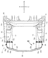
図1、図2に示すように、車体前部構造10は、車体11の左前側部11aにおいて車体前後方向に延出される左フロントサイドフレーム(フロントサイドフレーム)13と、左フロントサイドフレーム13の車幅方向外側に設けられる左フロントピラー14と、左フロントピラー14から車体前下方に傾斜して延出される左アッパメンバ(アッパメンバ)15と、左アッパメンバ15および左フロントサイドフレーム13を連結する左連結部(連結部)16とを備える。
As shown in FIGS. 1 and 2, the vehicle
また、車体前部構造10は、左連結部16および左フロントサイドフレーム13に設けられる左バンパビームエクステンション(バンパビームエクステンション)18と、前記左バンパビームエクステンション18に設けられるセンサ取付構造20と、左バンパビームエクステンション18および右バンパビームエクステンション(バンパビームエクステンション)18の各前端18aに架け渡されるバンパビーム22とを備える。
The vehicle
左フロントサイドフレーム13は、ロアダッシュパネル22の左側下方から車体前方へ向けて延出され、車体11の骨格を形成する部材である。左フロントサイドフレーム13の車幅方向外側に左フロントピラー14が設けられる。左フロントピラー14から左アッパメンバ15が左連結部16に向けて車体前下方へ傾斜して延出される。この状態において、左アッパメンバ15が、左フロントサイドフレーム13の車幅方向外側に設けられる。
The left
図3、図4に示すように、左アッパメンバ15の前部15aが左連結部16の外端部16aに連結される。また、左連結部16の内端部16bが左フロントサイドフレーム13の前部13aに連結される。すなわち、左フロントサイドフレーム13の前部13aが左アッパメンバ15の前部15aに左連結部16を介して連結される。
As shown in FIGS. 3 and 4, the
左フロントサイドフレーム13の前端13b、左連結部16の前端16cおよび左アッパメンバ15の前端15bに取付ブラケット23が設けられる。取付ブラケット23の車幅方向内側の部位23aに左バンパビームエクステンション18の後端18bが取り付けられる。
すなわち、左バンパビームエクステンション18の後端18bが、左フロントサイドフレーム13の前端13bおよび左連結部16の前端16cに取付ブラケット23を介して設けられる。この状態において、左バンパビームエクステンション18が、左フロントサイドフレーム13の前端13bおよび左連結部16の前端16cから車体前方へ向けて延出される。
Mounting
That is, the
図5に示すように、左バンパビームエクステンション18は、アルミニウム合金などの軽金属部材で形成される。具体的には、左バンパビームエクステンション18は、左取付部材19に取り付けられる連結プレート25と、連結プレート25の車幅方向内側に取り付けられる第1衝撃吸収部材26と、連結プレート25の車幅方向外側に取り付けられる第2衝撃吸収部材27とを備える。
すなわち、第1衝撃吸収部材26の車幅方向外側に第2衝撃吸収部材27が設けられる。
As shown in FIG. 5, the left
That is, the second
連結プレート25は、一例として、アルミニウム合金などの軽金属部材で均一の断面形状で延びるように押出成形される部材である。よって、連結プレート25を容易に成形(すなわち、製造)できる。
この連結プレート25は、左取付部材19に車体前方側からボルト28、ナット29(ナット29は図4参照)で取り付けられる。
As an example, the connecting
The connecting
第1衝撃吸収部材26は、一例として、アルミニウム合金などの軽金属部材で、車体前後方向へ均一の断面形状で延びるように押出成形される部材である。よって、第1衝撃吸収部材26を容易に成形(すなわち、製造)できる。第1衝撃吸収部材26の基部26aが連結プレート25の車幅方向の内側半部25aにミグ溶接で接合される。
具体的には、第1衝撃吸収部材26は、断面略矩形状の閉断面に形成される第1外周壁31と、第1外周壁31の内部を区分けする第1区分壁32とを有する。第1区分壁32は、一例として、断面略十字状(すなわち、格子状)に形成される。
As an example, the first
Specifically, the first
すなわち、第1衝撃吸収部材26は、第1外周壁31で閉断面が形成され、閉断面が第1区分壁32で複数の小区画(閉断面)33に格子状に区分けされる。よって、第1衝撃吸収部材26が、いわゆる略田の字状の閉断面に形成される。
第1外周壁31の車幅方向外側に第2衝撃吸収部材27が溶接により結合される。
That is, the first
The second
第2衝撃吸収部材27は、第1衝撃吸収部材26と同様に、アルミニウム合金などの軽金属部材で、車体前後方向へ均一の断面形状で延びるように押出成形される部材である。よって、第2衝撃吸収部材27を容易に成形(すなわち、製造)できる。
これにより、連結プレート25、第1衝撃吸収部材26および第2衝撃吸収部材27(すなわち、左バンパビームエクステンション18)を容易に製造できる。
Similar to the first
Thereby, the connecting
第2衝撃吸収部材27の基部27aが連結プレート25の車幅方向の外側半部25bにミグ溶接で接合される。具体的には、第2衝撃吸収部材27は、断面略U字形状(コ字形状)に形成される第2外周壁34と、第2外周壁34の内部を区分けする第2区分壁35とを有する。
The
第2外周壁34は、車幅方向内側に開口するように断面略U字形状に形成される。第2外周壁34の上内端部34aが第1外周壁31の上外端部31aに溶接で結合される。また、第2外周壁34の下内端部34bが第1外周壁31の下外端部31bに溶接で結合される。この結合状態において、第2外周壁34の内部が第2区分壁35で内外の小区画(閉断面)36に区画される。第2区分壁35は、断面略I字状に形成される。
よって、第2衝撃吸収部材27および第1外周壁31の外側壁により、いわゆる日の字状の閉断面が形成される。
The second outer
Therefore, a so-called sun-shaped closed cross section is formed by the second
第1外周壁31の車幅方向外側に第2衝撃吸収部材27が溶接により結合されることにより、左バンパビームエクステンション18の断面が大きく確保される。具体的には、左バンパビームエクステンション18の外面38は、上面38a、内側面38b、外側面38cおよび下面38dを有する。上面38a、内側面38b、外側面38cおよび下面38dで左バンパビームエクステンション18の外面38が断面略矩形状の外形に形成される。
The second
また、内側面38bや外側面38c(すなわち、左バンパビームエクステンション18)の高さ寸法H1より、上面38aや下面38d(すなわち、左バンパビームエクステンション18)の幅寸法W1が大きく形成される。さらに、左バンパビームエクステンション18の内部が複数の小区画33や内外の小区画36に区分けされる。
よって、軽衝突(すなわち、前面軽衝突:エアバッグを展開させる必要のない低速度領域)に対して左バンパビームエクステンション18の強度、剛性が好適に確保される。これにより、軽衝突の場合に、左バンパビームエクステンション18が圧縮(すなわち、軸圧壊)することを抑制できる。
Further, the width dimension W1 of the
Therefore, the strength and rigidity of the left
一方、例えば、バンパビームエクステンションの全域が十分に潰れきるような、高速正面衝突や微小ラップ衝突の場合に、左バンパビームエクステンション18を衝撃荷重で十分に圧縮させることができる。
On the other hand, for example, the left
また、左アッパメンバ15の前部15aを左フロントサイドフレーム13の前部13aに左連結部16で連結した。さらに、左バンパビームエクステンション18を左フロントサイドフレーム13の前端13bおよび左連結部16の前端16cに設けた。
よって、例えば、高速正面衝突や微小ラップ衝突の場合に、衝撃荷重を左フロントサイドフレーム13と左アッパメンバ15との両方で支えることができる。
これにより、左バンパビームエクステンション18を衝撃荷重で十分に圧縮(すなわち、軸圧壊)させることができる。
Further, the
Therefore, for example, in the case of a high-speed frontal collision or a minute lap collision, the impact load can be supported by both the left
Thereby, the left
このように、例えば、高速正面衝突や微小ラップ衝突の場合に、入力する衝撃荷重で左バンパビームエクステンション18を十分に圧縮させることにより、エネルギ吸収量を増すことができる。
ここで、微小ラップ衝突とは、車両の前部のうち車幅方向の1/4の左フロントサイドフレーム13の外側の前側部が車両、立木や電柱などの障害物に衝突することをいう。なお、微小ラップ衝突を、スモールオーバラップ衝突や、ナローオフセット衝突ともいう。
Thus, for example, in the case of a high-speed frontal collision or a minute lap collision, the amount of energy absorption can be increased by sufficiently compressing the left
Here, the minute lap collision means that the front side portion outside the left
図6に示すように、左バンパビームエクステンション18の前端18aにバンパビーム22の左端部22aが接合される。バンパビーム22は、一例として、アルミニウム合金などの軽金属部材で成形される部材である。バンパビーム22の左端部22aのビーム後壁(後部)22bが左バンパビームエクステンション18の前端18aにミグ溶接で結合(固定)される。
As shown in FIG. 6, the
また、図2に示すように、バンパビーム22の右端部22cのビーム後壁(後部)22dが右バンパビームエクステンション18の前端18aにミグ溶接で結合(固定)される。よって、左バンパビームエクステンション18が車幅方向へ延出される。
この状態において、バンパビーム22の左部22eが車幅方向外側で、かつ、車体後方へ向けて傾斜状に延出される。同様に、バンパビーム22の右部22fが車幅方向外側で、かつ、車体後方へ向けて傾斜状に延出される。
As shown in FIG. 2, the beam rear wall (rear part) 22 d of the
In this state, the
図6に戻って、バンパビーム22は、断面略矩形状の閉断面に形成されるビーム外周壁41と、ビーム外周壁41の内部を区分けする複数のビーム区分壁(一例として、上下のビーム区分壁)42とを有する。
ビーム外周壁41は、車体前方側に設けられるビーム前壁41aと、ビーム前壁41aの車体後方に設けられるビーム後壁41b、ビーム前壁41aの上端部およびビーム後壁41bの上端部を連結するビーム頂部41cと、ビーム前壁41aの下端部およびビーム後壁41bの下端部を連結するビーム底部41dとを備える。
Returning to FIG. 6, the
The beam outer
ビーム前壁41a、ビーム後壁41b、ビーム頂部41cおよびビーム底部41dでビーム外周壁41が断面略矩形状の中空閉断面に形成される。
ビーム外周壁41の内部に上下のビーム区分壁42が上下方向に間隔をおいて略平行に設けられる。よって、ビーム外周壁41の内部が上下のビーム区分壁42で複数の小区画43に上下方向に区分けされる。
すなわち、バンパビーム22が複数の小区画43を有する閉断面に形成される。よって、バンパビーム22が、いわゆる目の字状の閉断面に形成される。
The beam
Inside the beam outer
That is, the
このように、バンパビーム22のビーム外周壁41が中空閉断面に形成され、上下のビーム区分壁42で複数の小区画43に上下方向に区分けされる。バンパビーム22は、軽衝突(すなわち、エアバッグを展開させる必要のない低速度領域)に対して曲げおよび潰れ変形可能に形成される。
Thus, the outer
また、バンパビーム22の左端部22aのビーム後壁41bが左バンパビームエクステンション18の前端18aにミグ溶接で結合される。さらに、軽衝突に対して左バンパビームエクステンション18の強度、剛性が確保されている。
よって、軽衝突の場合に、バンパビーム22を曲げおよび潰れ変形して衝撃荷重を吸収することができる。
Further, the beam
Therefore, in the case of a light collision, the
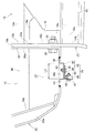
図3に戻って、左バンパビームエクステンション18の外面38のうち外側面38cにセンサ取付構造20が設けられる。センサ取付構造20は、左バンパビームエクステンション18の外側面38cに設けられる支持手段45と、支持手段45に取り付けられるエアバッグセンサ(前部衝突センサ(FCS:Front Crash Sensor))46とを備える。
Returning to FIG. 3, the
図7、図8に示すように、支持手段45は、左バンパビームエクステンション18の外側面38cに設けられるステイ47と、ステイ47に設けられるブラケット48とを備える。
ステイ47は、側面視略矩形状に形成される頂部51と、頂部51の前端に形成される前脚部52と、前脚部52の内端に形成される前接合部53と、頂部51の後端に形成される後脚部54と、後脚部54の内端に形成される後接合部55とを有する。
As shown in FIGS. 7 and 8, the support means 45 includes a
The
頂部51の前端から左バンパビームエクステンション18の外側面38cへ向けて前脚部52が折り曲げられる。また、前脚部52の内端から左バンパビームエクステンション18の外側面38cに沿って前接合部53が車体前方へ向けて折り曲げられる。
さらに、頂部51の後端から左バンパビームエクステンション18の外側面38cへ向けて後脚部54が折り曲げられる。また、後脚部54の内端から左バンパビームエクステンション18の外側面38cに沿って後接合部55が車体後方へ向けて折り曲げられる。
The
Further, the
頂部51、前脚部52、前接合部53、後脚部54、後接合部55でステイ47が平面視略ハット状に形成される。さらに、ステイ47は、左バンパビームエクステンション18と同様に、アルミニウム合金で形成される。
The top 47, the
前接合部53が左バンパビームエクステンション18の外側面38cのうち前部位38eに接合される。後接合部55が、左バンパビームエクステンション18の外側面38cのうち、前接合部53より車体後方の部位38fに間隔L1をおいて接合される。すなわち、前接合部53および後接合部55が左バンパビームエクステンション18の外側面38cに車体前後方向へ間隔L1をおいて設けられる。
この状態をおいて、頂部51が左バンパビームエクステンション18の外側面38cから車幅方向外側に離れた位置に配置される。
The front
In this state, the
ステイ47の頂部51にブラケット48が設けられる。ブラケット48は鋼板で形成される。具体的には、ブラケット48は、頂部51に取り付けられる取付基部56と、取付基部56から張り出される張出部57と、取付基部56および張出部57に形成されるフランジ58と、張出部57に形成されるコネクタプロテクタ59とを有する。
A
ステイ47の頂部51に沿って取付基部56が接触された状態において、取付基部56が頂部51にボルト61、ナット62(すなわち、締結部材)で締結される。取付基部56の前端から車幅方向外側に向けて張出部57が折り曲げられる。取付基部56および張出部57でブラケット48が平面視略L字状に形成される。
In a state where the
ここで、ステイ47がアルミニウム合金で形成され、ブラケット48が鋼板で形成される。よって、アルミニウム合金製の頂部51に鋼製の取付基部56がボルト61、ナット62に取り付けられる。このボルト61、ナット62に電食防止の塗装が施される。
これにより、ステイ47とボルト61、ナット62との間の電食を抑えることができ、ステイ47やボルト61、ナット62の耐久性を高くできる。
なお、電食防止の塗装として、異材の電位差を減少する防錆塗装が用いられ、一例として、「GEOMET720」(商品名)が挙げられる。
Here, the
Thereby, the electrolytic corrosion between the
In addition, as an anti-corrosion coating, a rust-proof coating that reduces the potential difference between different materials is used, and one example is “GEOMET720” (trade name).
張出部57にエアバッグセンサ46がボルト63、ナット64で取り付けられる。この状態において、エアバッグセンサ46の下端46aに対してエアバッグセンサ46の上端46bが車幅方向内側で、かつ、上方に配置される。
すなわち、エアバッグセンサ46が車幅方向内側で、かつ、上方へ向けて傾斜状に配置される。
The
In other words, the
エアバッグセンサ46は、センサケース65内に検知部(すなわち、Gチップ)66が内蔵されている。
エアバッグセンサ46の上端46bにワイヤハーネス67が接続されている。ワイヤハーネス67がエアバッグセンサ46の上端46bから車幅方向内側で、かつ、上方へ向けて傾斜状に延ばされる。
The
A
取付基部56および張出部57が平面視略L字状に形成されることにより、取付基部56および張出部57が交差する部位に折曲部68が形成される。取付基部56、張出部57、および折曲部の各下端(すなわち、ブラケット48の下端)48aにフランジ58が連続するように形成される。
By forming the
具体的には、フランジ58は、取付基部56の下端から車幅方向外側に折り曲げられる第1フランジ部位58aと、張出部57の下端から車体後方に折り曲げられる第2フランジ部位58bと、折曲部の下端から第1フランジ部位58aや第2フランジ部位58bに連結するように折り曲げられる第3フランジ部位58cとを有する。
このように、ブラケット48の下端48aにフランジ58を形成した。よって、ブラケット48の強度、剛性をフランジ58で高くできる。これにより、ブラケット48の共振固有値を高くでき、エアバッグセンサ46の耐ノイズ性(耐振動性)を高くできる。
Specifically, the
Thus, the
ブラケット48の上端48b(具体的には、張出部57の上端57a)からコネクタプロテクタ59が突出される。コネクタプロテクタ59は、ワイヤハーネス67の車体前方側に配置され、ワイヤハーネス67に沿って車幅方向内側で、かつ、上方へ向けて傾斜状に突出される。
よって、エアバッグセンサ46を衝突物の干渉範囲に設けた場合でも、エアバッグセンサ46のワイヤハーネス67をコネクタプロテクタ59で保護できる。これにより、例えば、高速正面衝突、微小ラップ衝突、オフセット衝突の際に、エアバッグセンサ46に対するワイヤハーネス67の接続が切断されることを防止できる。
The
Therefore, even when the
このように、支持手段45のステイ47が平面視略ハット状に形成され、ステイ47の前接合部53および後接合部55が左バンパビームエクステンション18の外側面38cに設けられる。よって、ステイ47の強度、剛性を高くできる。
さらに、ステイ47が平面視略ハット状に形成されることにより、ステイ47の頂部51を左バンパビームエクステンション18の外側面38cから離すことができる。
Thus, the
Furthermore, by forming the
このステイ47の頂部51にブラケット48の取付基部56が設けられ、取付基部56から張出部57を張り出した。よって、張出部57の張出量(延出量)が小さく抑えられる。この張出部57にエアバッグセンサ46が取り付けられる。
これにより、エアバッグセンサ46を支持手段45で支持した状態において、支持手段45の振動の固有値を高くして、エアバッグセンサ46の耐ノイズ性(耐振動性)を高くできる。したがって、エアバッグの展開に必要な衝突情報をエアバッグセンサ46で精度よく早期に検知できる。
An
Thereby, in a state where the
ここで、例えば、エアバッグを作動させるべき速度下限(具体的には、中速度領域)でのオフセット衝突の際に、相手車両にブラケット48(すなわち、張出部57)が当接することが考えられる。
そこで、ブラケット48を鋼板で形成した。これにより、ブラケット48の張出部57が相手車両に当接した場合に、張出部57に入力する衝撃荷重に対して、張出部57の折曲がり状態を容易に調整(コントロール)できる。
Here, for example, in the case of an offset collision at the lower speed limit (specifically, the middle speed range) at which the airbag is to be operated, it is considered that the bracket 48 (that is, the overhanging portion 57) abuts the opponent vehicle. It is done.
Therefore, the
図4に戻って、左バンパビームエクステンション18の外側面38cに支持手段45が設けられ、支持手段45にエアバッグセンサ46が取り付けられる。
ここで、例えば、エアバッグを展開させる必要のない低速度領域の軽衝突の場合、バンパビーム22が曲げおよび潰れ変形して衝撃荷重を吸収する。一方、左バンパビームエクステンション18は軽衝突に対して十分な強度、剛性を有する。よって、軽衝突の場合、左バンパビームエクステンション18の圧縮(すなわち、軸圧壊)は少ない。
これにより、軽衝突の場合には、エアバッグセンサ46の車体後方への移動を抑え、エアバッグセンサ46が軽衝突を不要に検知してエアバッグが展開することを防止できる。
Returning to FIG. 4, support means 45 is provided on the
Here, for example, in the case of a light collision in a low speed region where it is not necessary to deploy the airbag, the
Thereby, in the case of a light collision, the movement of the
ところで、エアバッグを作動させるべき速度下限でのオフセット衝突の場合、オフセット衝突の初期において、相手車両の最前部の比較的柔らかい部位に左バンパビームエクステンション18の前端18aが侵入する。このため、相手車両の比較的柔らかい部位が支持手段45(特に、張出部57)と干渉して張出部57が車体後方へ折れ曲がり、支持手段45が車体後方へ後退する。
By the way, in the case of an offset collision at the lower speed limit at which the airbag is to be activated, the
よって、支持手段45とともにエアバッグセンサ46が車体後方へ後退し、エアバッグの展開に必要な衝突情報をエアバッグセンサ46で精度よく早期に検知できる。これにより、オフセット衝突の初期において、エアバッグを展開させることができる。
ここで、オフセット衝突とは、車両の前部のうち一部(車体前面の幅の約半分)が車両などの障害物に衝突することをいう。
Therefore, the
Here, the offset collision means that a part (about half of the width of the front surface of the vehicle body) of the front part of the vehicle collides with an obstacle such as a vehicle.
また、ステイ47の前接合部53および後接合部55が左バンパビームエクステンション18の外側面38cに車体前後方向へ間隔L1をおいて設けられている。すなわち、ステイ47は左バンパビームエクステンション18が圧縮をする方向の強度、剛性が好適に低く抑えられている。
よって、左バンパビームエクステンション18の全域が十分に潰れきるような、高速正面衝突や微小ラップ衝突の場合、入力する衝撃荷重により左バンパビームエクステンション18が車体後方へ圧縮する際に、ステイ47の前接合部53を良好に車体後方へ移動させることができる。
Further, the front
Therefore, in the case of a high-speed frontal collision or minute lap collision in which the entire area of the left
ステイ47の前接合部53を良好に車体後方へ移動させることにより、左バンパビームエクステンション18の圧縮(潰れ変形)をステイ47で阻害する虞がない。これにより、左バンパビームエクステンション18を車体後方へ安定的に圧縮させることができ、かつ、左フロントサイドフレーム13の変形を安定化させることができる。
したがって、左バンパビームエクステンション18の圧縮に追従させてエアバッグセンサ46を車体後方へ好適に後退させて、エアバッグセンサ46で高速正面衝突や微小ラップ衝突の衝突情報を精度よく早期に検知できる。
By properly moving the front
Accordingly, the
図9に示すように、左バンパビームエクステンション18に左側の支持手段45を介して左側のエアバッグセンサ46が取り付けられる。また、右バンパビームエクステンション18に右側の支持手段45を介して右側のエアバッグセンサ46が取り付けられる。左側のエアバッグセンサ46は、右側のエアバッグセンサ46と同一部材である。
As shown in FIG. 9, the
ここで、例えば、左側のエアバッグセンサ46と右側のエアバッグセンサ46が鉛直に配置された場合、左側のエアバッグセンサ46の検知部66がボルト63の車幅方向外側に配置される。一方、右側のエアバッグセンサ46の検知部66がボルト66の車幅方向内側に配置される。
よって、左側の検知部66は、右側の検知部66より車体中心72からの距離が大きくなる。このため、例えば、車体前部構造10が高速正面衝突した場合、左側の検知部66と右側の検知部66とに左右の差が生じ、衝突形態を正確に判定することが難しい。
Here, for example, when the
Therefore, the
そこで、左側のエアバッグセンサ46を車幅方向内側で、かつ、上方へ向けて傾斜状に取り付けるようにした。よって、左側のエアバッグセンサ46は、鉛直に配置された場合と比べて、左側の検知部66が矢印Aの如く車幅方向内側に配置される。
一方、右側のエアバッグセンサ46を車幅方向内側で、かつ、上方へ向けて傾斜状に取り付けるようにした。よって、右側のエアバッグセンサ46は、鉛直に配置された場合と比べて、右側の検知部66が矢印Bの如く車幅方向外側に配置される。
Therefore, the
On the other hand, the
すなわち、左側の検知部66から車体中心72までの距離L2を、右側の検知部66から車体中心72までの距離L3と同一にできる。これにより、例えば、車体前部構造10が高速正面衝突した場合、左側の検知部66と右側の検知部66とに検知差が生じることを抑制できる。
したがって、左側のエアバッグセンサ46および右側のエアバッグセンサ46で高速正面衝突の衝突形態を正確に判定できる。
That is, the distance L2 from the
Therefore, the collision mode of the high-speed frontal collision can be accurately determined by the
また、左バンパビームエクステンション18に取り付ける左側のエアバッグセンサ46と、右バンパビームエクステンション18に取り付ける右側のエアバッグセンサ46とを同一部材とした。
このように、左側のエアバッグセンサ46および右側のエアバッグセンサ46の部品を共通化することにより、センサ取付構造20のコストを抑えることができる。
The
Thus, by sharing the parts of the
さらに、左側のエアバッグセンサ46および右側のエアバッグセンサ46を傾斜させ、各エアバッグセンサ46の上端46bをステイ47側に近づけた。よって、左側のエアバッグセンサ46の上端46bに接続されるワイヤハーネス67を左側のステイ47側に近づけることが可能になる。
同様に、右側のエアバッグセンサ46の上端46bに接続されるワイヤハーネス67を右側にステイ47側に近づけることが可能になる。
Further, the
Similarly, the
これにより、左側のワイヤハーネス67を保護するコネクタプロテクタ59を、左側のステイ47に近づけることができ、左側の支持手段45の振動の固有値を高くできる。同様に、右側のワイヤハーネス67を保護するコネクタプロテクタ59を、右側の各ステイ47に近づけることができ、右側の支持手段45の振動の固有値を高くできる。
したがって、左右側のエアバッグセンサ46の共振を抑制して、左右側のエアバッグセンサ46による誤検知を一層良好に防止できる。
Accordingly, the
Therefore, the resonance of the left and
また、左側のエアバッグセンサ46を傾斜させることにより、左側のエアバッグセンサ46の高さH2を低く抑えることができる。同様に、右側のエアバッグセンサ46を傾斜させることにより、右側のエアバッグセンサ46の高さH3を低く抑えることができる。よって、左側のエアバッグセンサ46の上方の空間74を確保でき、かつ、右側のエアバッグセンサ46の上方の空間75を確保できる。
これにより、空間74や空間75に周辺部品(ヘッドライト、冷却配管や、フォグランプなどの小型灯火)を配置する際に、周辺部品のレイアウトの自由度を増すことができる。また、周辺部品の性能への影響を少なく抑えることができる。
Further, by tilting the
Accordingly, when peripheral components (small lights such as headlights, cooling pipes, and fog lamps) are arranged in the
つぎに、車体前部構造10に軽衝突(すなわち、エアバッグを展開させる必要のない低速度領域)により衝撃荷重F1が入力した場合に、入力した衝撃荷重F1を車体前部構造10で吸収する例を図10に基づいて説明する。
Next, when the impact load F1 is input to the vehicle
図10(a)に示すように、車体前部構造10のバンパビーム22に軽衝突により衝撃荷重F1が入力する。
ここで左バンパビームエクステンション18の幅寸法W1が大きく形成され、左バンパビームエクステンション18の内部が複数の小区画33や内外の小区画36(図5参照)に区分けされている。同様に、右バンパビームエクステンション18の幅寸法W1が大きく形成され、右バンパビームエクステンション18の内部 が複数の小区画や内外の小区画に区分けされている。
よって、バンパビーム22に入力する衝撃荷重F1に対して左バンパビームエクステンション18や右バンパビームエクステンション18の強度、剛性が好適に確保される。
As shown in FIG. 10A, an impact load F1 is input to the
Here, the width dimension W1 of the left
Therefore, the strength and rigidity of the left
図10(b)に示すように、バンパビーム22に入力する衝撃荷重F1により、バンパビーム22が曲げおよび潰れ変形する。また、左バンパビームエクステンション18の先端部18cや右バンパビームエクステンション18の先端部18cが変形する。
バンパビーム22、左バンパビームエクステンション18や右バンパビームエクステンション18の各先端部18cの変形により軽衝突により入力する衝撃荷重F1を吸収できる。
As shown in FIG. 10B, the
The impact load F <b> 1 input by a light collision can be absorbed by the deformation of the
よって、左バンパビームエクステンション18や右バンパビームエクステンション18が車体後方へ圧縮(すなわち、軸圧壊)することを抑制できる。これにより、左側のエアバッグセンサ46や右側のエアバッグセンサ46を静止状態に保つことができ、左右のエアバッグセンサ46で軽衝突を不要に検知してエアバッグが展開することを防止できる。
Therefore, it is possible to suppress the left
ついで、エアバッグを作動させるべき速度下限(具体的には、中速度領域)でのオフセット衝突により車体前部構造10に衝撃荷重F2が入力した場合に、入力した衝撃荷重F2でエアバッグを展開させる例を図11に基づいて説明する。
なお、図11(b)においては、作用の理解を容易にするために左側の部材について説明して右側の部材の説明を省略する。
Next, when the impact load F2 is input to the vehicle
In FIG. 11B, in order to facilitate understanding of the operation, the left member will be described, and the description of the right member will be omitted.
図11(a)に示すように、車体前部構造10のバンパビーム22にオフセット衝突により衝撃荷重F2が入力する。バンパビーム22に入力する衝撃荷重F2により、バンパビーム22が曲げおよび潰れ変形する。また、左バンパビームエクステンション18の先端部18cや右バンパビームエクステンション18の先端部18cが変形する。
As shown in FIG. 11A, an impact load F2 is input to the
図11(b)に示すように、オフセット衝突の初期において、相手車両82の最前部の比較的柔らかい部位82aに左バンパビームエクステンション18の前端18aが矢印Cの如く侵入する。
このため、相手車両の比較的柔らかい部位82aが支持手段45(特に、張出部57)と干渉する。張出部57が車体後方へ折れ曲がり、支持手段45とともにエアバッグセンサ46が車体後方へ矢印Dの如く後退する。
As shown in FIG. 11B, at the initial stage of the offset collision, the
For this reason, the relatively
よって、支持手段45とともにエアバッグセンサ46が車体後方へ矢印Dの如く後退する。エアバッグセンサ46を後退させることにより、エアバッグの展開に必要な衝突情報をエアバッグセンサ46で精度よく早期に検知できる。
これにより、オフセット衝突の初期において、エアバッグを展開させることができる。
Therefore, the
Thereby, the airbag can be deployed at the initial stage of the offset collision.
つぎに、車体前部構造10に高速正面衝突(すなわち、左バンパビームエクステンション18や右バンパビームエクステンション18の全域が十分に潰れきるような高速度領域)により衝撃荷重F3が入力した場合に、入力した衝撃荷重F3でエアバッグを展開させる例を図12、図13に基づいて説明する。
なお、図12(b)においては、作用の理解を容易にするために左側の部材について説明して右側の部材の説明を省略する。
Next, when the impact load F3 is input to the vehicle
In FIG. 12B, in order to facilitate understanding of the operation, the left member is described, and the description of the right member is omitted.
図12(a)に示すように、車体前部構造10のバンパビーム22に高速正面衝突により衝撃荷重F3が入力する。バンパビーム22に入力する衝撃荷重F3により、バンパビーム22が曲げおよび潰れ変形する。また、左バンパビームエクステンション18の先端部18cや右バンパビームエクステンション18の先端部18cが変形する。
As shown in FIG. 12A, an impact load F3 is input to the
図12(b)に示すように、左アッパメンバ15の前部15aが左フロントサイドフレーム13の前部13aに左連結部16で連結されている。また、左バンパビームエクステンション18が左フロントサイドフレーム13の前端13bおよび左連結部16の前端16cに設けられている。
As shown in FIG. 12B, the
よって、高速正面衝突の場合に、衝撃荷重F3を左フロントサイドフレーム13と左アッパメンバ15との両方で支えることができる。これにより、左バンパビームエクステンション18の全域を衝撃荷重F3で十分に車体後方へ向けて矢印Eの如く圧縮(すなわち、軸圧壊)できる。
Therefore, the impact load F3 can be supported by both the left
図13に示すように、ステイ47の前接合部53および後接合部55が左バンパビームエクステンション18の外側面38cに車体前後方向へ間隔L1をおいて設けられている。よって、高速正面衝突により左バンパビームエクステンション18を車体後方へ矢印Eの如く圧縮する際に、ステイ47の前接合部53を車体後方へ矢印Eの如く移動させることができる。
As shown in FIG. 13, the front
これにより、左バンパビームエクステンション18の圧縮(潰れ変形)をステイ47で阻害する虞がない。したがって、左バンパビームエクステンション18を車体後方へ向けて矢印Eの如く安定的に圧縮させることができ、かつ、左フロントサイドフレーム13の変形を安定化させることができる。
このように、左バンパビームエクステンション18の全域を衝撃荷重F3で十分に圧縮することにより、衝撃荷重F3のエネルギ吸収量を十分に確保できる。
Thereby, there is no possibility that the
Thus, by sufficiently compressing the entire area of the left
ここで、左バンパビームエクステンション18を圧縮させる際に、圧縮に追従させて支持手段45(特に、ステイ47やブラケット48)を車体後方へ矢印Eの如く変形させことができる。よって、ブラケット48とともにエアバッグセンサ46を車体後方へ矢印Eの如く後退させることができる。
これにより、エアバッグセンサ46で高速正面衝突の衝突情報を精度よく早期に検知できる。したがって、高速正面衝突の初期において、エアバッグを展開させることができる。
Here, when the left
Thereby, the
ここで、左バンパビームエクステンション18の全域が十分に潰れきるような微小ラップ衝突の場合も、高速正面衝突の場合と同様に、衝撃荷重を左フロントサイドフレーム13と左アッパメンバ15との両方で支えることができる。また、衝撃荷重でステイ47の前接合部53を車体後方へ移動させることができる。
これにより、左バンパビームエクステンション18の全域を衝撃荷重で十分に圧縮することにより、衝撃荷重のエネルギ吸収量を十分に確保できる。
Here, even in the case of a micro lap collision in which the entire area of the left
Thereby, by sufficiently compressing the entire area of the left
また、左バンパビームエクステンション18を衝撃荷重で十分に圧縮することにより、エアバッグセンサ46を車体後方へ後退させることができる。これにより、微小ラップ衝突の場合も、高速正面衝突の場合と同様に、エアバッグセンサ46で衝突情報を精度よく早期に検知して、衝突の初期において、エアバッグを展開させることができる。
Further, by sufficiently compressing the left
なお、本発明に係るエアバッグセンサ取付構造は、前述した実施例に限定されるものではなく適宜変更、改良などが可能である。
例えば、前記実施例では、連結プレート25、第1衝撃吸収部材26および第2衝撃吸収部材27をアルミニウム合金などの軽金属部材で成形した例について説明したが、これに限定するものではない。
例えば、連結プレート25、第1衝撃吸収部材26および第2衝撃吸収部材27を鋼板で形成することも可能である。この場合でも、連結プレート25と第1衝撃吸収部材26とをミグ溶接で接合し、連結プレート25と第2衝撃吸収部材27とをミグ溶接で接合する。
The airbag sensor mounting structure according to the present invention is not limited to the above-described embodiment, and can be changed or improved as appropriate.
For example, in the above-described embodiment, the example in which the connecting
For example, the connecting
また、前記実施例では、左バンパビームエクステンション18の外面38のうち外側面38cにセンサ取付構造20を設けた例について説明したが、これに限定するものではない。例えば、左バンパビームエクステンション18の外面38のうち上面38a、内側面38bや下面38dにセンサ取付構造20を設けることも可能である。
Moreover, although the said Example demonstrated the example which provided the
さらに、前記実施例では、ステイ47の頂部51にブラケット48の取付基部56をボルト61、ナット62で取り付ける例について説明したが、これに限らないで、リベットなどの他の締結部材で取り付けることも可能である。
Further, in the above-described embodiment, the example in which the mounting
また、前記実施例では、ブラケット48の下端48aにフランジ58を連続させて形成する例について説明したが、これに限らないで、ブラケット48の上端48bにフランジを連続させするように形成することも可能である。
In the above-described embodiment, an example in which the
さらに、前記実施例では、張出部57の上端57aからコネクタプロテクタ59を突出させる例について説明したが、これに限定するものではない。例えば、エアバッグセンサ46からワイヤハーネス67を下方に延ばした場合、ワイヤハーネス67に沿うようにコネクタプロテクタ59を張出部57の下端から突出させることも可能である。
Furthermore, although the said Example demonstrated the example which protrudes the
また、前記実施例で示した車体前部構造、車体、左右のフロントサイドフレーム、左右のアッパメンバ、左右の連結部、左右のバンパビームエクステンション、センサ取付構造、バンパビーム、ビーム後壁、エアバッグセンサ、ステイ、ブラケット、頂部、前接合部、後接合部、取付基部、張出部、フランジ、コネクタプロテクタおよび折曲部などの形状や構成は例示したものに限定するものではなく適宜変更が可能である。 Further, the vehicle body front structure, the vehicle body, the left and right front side frames, the left and right upper members, the left and right connecting portions, the left and right bumper beam extensions, the sensor mounting structure, the bumper beam, the beam rear wall, the airbag sensor, The shape and configuration of the stay, bracket, top, front joint, rear joint, mounting base, overhang, flange, connector protector, bent portion, etc. are not limited to those illustrated, but can be changed as appropriate. .
本発明は、フロントサイドフレームの車体前方にエアバッグセンサが取り付けられる、エアバッグセンサ取付構造を備えた自動車への適用に好適である。 The present invention is suitable for application to an automobile having an airbag sensor mounting structure in which an airbag sensor is mounted in front of a vehicle body of a front side frame.
10 車体前部構造
11 車体
11a 左右の前側部(車体の両前側部)
13 左右のフロントサイドフレーム(フロントサイドフレーム)
13b 左右のフロントサイドフレームの前端
13a 左右のフロントサイドフレームの前部
15 左右のアッパメンバ(アッパメンバ)
15a 左右のアッパメンバの前部
16 左右の連結部(連結部)
16c 左右の連結部の前端
18 左右のバンパビームエクステンション(バンパビームエクステンション)
18a 左右のバンパビームエクステンションの前端
20 センサ取付構造(エアバッグセンサ取付構造)
22 バンパビーム
22a,22c バンパビームの両端部
22b,22d 両端部のビーム後壁(後部)
38 左右のバンパビームエクステンションの外面
38c 左右のバンパビームエクステンションの外側面
45 支持手段
46 エアバッグセンサ
47 ステイ
48 ブラケット
48a ブラケットの下端
48b ブラケットの上端
51 頂部
53 前接合部
55 後接合部
56 取付基部
57 張出部
57a 張出部の上端
58 フランジ
59 コネクタプロテクタ
61,62 ボルト、ナット(締結部材)
68 折曲部
F3 衝撃荷重
H1 左バンパビームエクステンションの高さ寸法
L1 前接合部および後接合部の車体前後方向への間隔
L2 左側のエアバッグセンサから車体中心までの距離
L3 右側のエアバッグセンサから車体中心までの距離
W1 左バンパビームエクステンションの幅寸法
DESCRIPTION OF
13 Left and right front side frames (front side frames)
13b Front ends of left and right front side frames 13a Front portions of left and right front side frames 15 Left and right upper members (upper members)
15a Front portions of left and right
16c Front end of left and right connecting
18a Front end of left and right
22
38 Outer surfaces of left and right
68 Folded part F3 Impact load H1 Height of left bumper beam extension L1 Distance between front and rear joints in longitudinal direction of vehicle body L2 Distance from left airbag sensor to center of vehicle body L3 From right airbag sensor Distance to vehicle center W1 Width dimension of left bumper beam extension
Claims (10)
前記バンパビームエクステンションの外面に設けられ、車体前方から入力する衝撃荷重で前記バンパビームエクステンションが圧縮される際に、前記バンパビームエクステンションの圧縮に追従して車体後方へ後退する支持手段と、
該支持手段に取り付けられるエアバッグセンサと、
を備えることを特徴とするエアバッグセンサ取付構造。 Front side frames are extended in the front-rear direction of the vehicle body on both front sides of the vehicle body, a bumper beam extension is extended from the front end of the front side frame toward the front of the vehicle body, and a bumper beam is provided at the front end of the bumper beam extension. In the airbag sensor mounting structure that is mounted on the vehicle body front structure,
A support means provided on an outer surface of the bumper beam extension, and retracts backward in the vehicle body following the compression of the bumper beam extension when the bumper beam extension is compressed by an impact load input from the front of the vehicle body;
An airbag sensor attached to the support means;
An airbag sensor mounting structure comprising:
前記バンパビームエクステンションの外面に設けられる前接合部および後接合部を有し、平面視略ハット状に形成されるステイと、
該ステイのうち前記バンパビームエクステンションの外面から離れた頂部に取付基部が設けられ、該取付基部から張り出される張出部に前記エアバッグセンサが取り付けられるブラケットと、を備え、
前記取付基部および前記張出部でブラケットが平面視略L字状に形成される、請求項1記載のエアバッグセンサ取付構造。 The support means is
A stay having a front joint portion and a rear joint portion provided on the outer surface of the bumper beam extension, and formed in a substantially hat shape in plan view;
A mounting base is provided at the top of the stay away from the outer surface of the bumper beam extension, and a bracket to which the airbag sensor is attached to a projecting part that projects from the mounting base,
The airbag sensor mounting structure according to claim 1, wherein a bracket is formed in a substantially L shape in plan view at the mounting base and the overhanging portion.
前記ステイに前記ブラケットが締結部材で締結され、
該締結部材に電食防止の塗装が施される、請求項3記載のエアバッグセンサ取付構造。 The bumper beam extension and the stay are formed of an aluminum alloy,
The bracket is fastened to the stay with a fastening member,
The airbag sensor mounting structure according to claim 3, wherein the fastening member is painted to prevent electrolytic corrosion.
中空断面に形成され、両端部の後部が前記バンパビームエクステンションの前端に固定され、
前記バンパビームエクステンションは軽衝突に対して強度、剛性が確保される、請求項1記載のエアバッグセンサ取付構造。 The bumper beam is
Formed in a hollow cross section, the rear part of both ends fixed to the front end of the bumper beam extension,
The airbag sensor mounting structure according to claim 1, wherein the bumper beam extension is ensured in strength and rigidity against a light collision.
中空断面に形成され、両端部の後部が前記バンパビームエクステンションの前端に固定され、
前記バンパビームエクステンションは軽衝突に対して剛性が確保され、
前記ステイは、
前記前接合部および前記後接合部が前記バンパビームエクステンションの外面に車体前後方向へ間隔をおいて設けられる、請求項2記載のエアバッグセンサ取付構造。 The bumper beam is
Formed in a hollow cross section, the rear part of both ends fixed to the front end of the bumper beam extension,
The bumper beam extension is secured against light collisions,
The stay
The airbag sensor mounting structure according to claim 2, wherein the front joint portion and the rear joint portion are provided on the outer surface of the bumper beam extension with an interval in the front-rear direction of the vehicle body.
前記取付基部、前記張出部、前記取付基部および前記張出部が交差する折曲部に連続し、かつ、前記ブラケットの上端または下端に形成されるフランジと、
前記ブラケットの上端または下端から突出されるコネクタプロテクタと、を有する、請求項2記載のエアバッグセンサ取付構造。 The bracket is
A flange formed on the upper end or the lower end of the bracket, which is continuous with the bent portion where the mounting base portion, the protruding portion, the mounting base portion and the protruding portion intersect;
The airbag sensor mounting structure according to claim 2, further comprising a connector protector protruding from an upper end or a lower end of the bracket.
左側のエアバッグセンサおよび右側のエアバッグセンサが傾斜されることにより、
左側のエアバッグセンサから車体中心までの距離と、右側のエアバッグセンサから車体中心までの距離とを同一とする、請求項1記載のエアバッグセンサ取付構造。 The airbag sensor is attached to the left bumper beam extension of the vehicle body and the right bumper beam extension of the vehicle body,
By tilting the left airbag sensor and the right airbag sensor,
The airbag sensor mounting structure according to claim 1, wherein a distance from the left airbag sensor to the vehicle body center is the same as a distance from the right airbag sensor to the vehicle body center.
外形が断面略矩形状で、かつ、高さ寸法より幅寸法が大きく形成され、内部が複数の閉断面に区分けされる、請求項1記載のエアバッグセンサ取付構造。 The bumper beam extension is
The airbag sensor mounting structure according to claim 1, wherein the outer shape is substantially rectangular in cross section, the width is formed larger than the height, and the inside is divided into a plurality of closed cross sections.
該アッパメンバの前部を前記フロントサイドフレームの前部に連結する連結部と、を備え、
前記バンパビームエクステンションは、
前記フロントサイドフレームの前端および前記連結部の前端に設けられる、請求項1記載のエアバッグセンサ取付構造。 An upper member provided outside the front side frame in the vehicle width direction;
A connecting portion for connecting a front portion of the upper member to a front portion of the front side frame,
The bumper beam extension is
The airbag sensor mounting structure according to claim 1, wherein the airbag sensor mounting structure is provided at a front end of the front side frame and a front end of the connecting portion.
Priority Applications (3)
| Application Number | Priority Date | Filing Date | Title |
|---|---|---|---|
| JP2016031158A JP6317379B2 (en) | 2016-02-22 | 2016-02-22 | Airbag sensor mounting structure |
| CN201710032617.5A CN107097746B (en) | 2016-02-22 | 2017-01-16 | Airbag sensor mounting structure |
| US15/439,347 US10131302B2 (en) | 2016-02-22 | 2017-02-22 | Airbag sensor attachment structure |
Applications Claiming Priority (1)
| Application Number | Priority Date | Filing Date | Title |
|---|---|---|---|
| JP2016031158A JP6317379B2 (en) | 2016-02-22 | 2016-02-22 | Airbag sensor mounting structure |
Publications (2)
| Publication Number | Publication Date |
|---|---|
| JP2017149192A true JP2017149192A (en) | 2017-08-31 |
| JP6317379B2 JP6317379B2 (en) | 2018-04-25 |
Family
ID=59631484
Family Applications (1)
| Application Number | Title | Priority Date | Filing Date |
|---|---|---|---|
| JP2016031158A Expired - Fee Related JP6317379B2 (en) | 2016-02-22 | 2016-02-22 | Airbag sensor mounting structure |
Country Status (3)
| Country | Link |
|---|---|
| US (1) | US10131302B2 (en) |
| JP (1) | JP6317379B2 (en) |
| CN (1) | CN107097746B (en) |
Cited By (2)
| Publication number | Priority date | Publication date | Assignee | Title |
|---|---|---|---|---|
| JP2019199202A (en) * | 2018-05-17 | 2019-11-21 | 株式会社Soken | Collision detection device |
| JP2023515495A (en) * | 2020-02-21 | 2023-04-13 | シェイプ・コープ | Beam assembly with multiple hollow structures |
Families Citing this family (8)
| Publication number | Priority date | Publication date | Assignee | Title |
|---|---|---|---|---|
| DE102015117005A1 (en) * | 2015-10-06 | 2017-04-06 | Benteler Automobiltechnik Gmbh | crash box |
| JP6387081B2 (en) * | 2016-12-28 | 2018-09-05 | 本田技研工業株式会社 | Stay dropout structure when collision load is input |
| US10328879B2 (en) * | 2017-06-30 | 2019-06-25 | Honda Motor Co., Ltd. | Bumper bean design for crash signal separation |
| JP6575015B2 (en) * | 2017-07-07 | 2019-09-18 | 本田技研工業株式会社 | Body structure |
| DE102017009057B4 (en) * | 2017-09-27 | 2019-07-11 | Audi Ag | Arrangement of a sensor-active surface having sensor on an external attachment of a vehicle |
| JP6863209B2 (en) * | 2017-09-29 | 2021-04-21 | トヨタ自動車株式会社 | Sensor protector and vehicle equipped with it |
| JP7053421B2 (en) * | 2018-09-17 | 2022-04-12 | 本田技研工業株式会社 | Body structure |
| JP7182655B2 (en) * | 2021-03-09 | 2022-12-02 | 本田技研工業株式会社 | Vehicle sensor mounting structure |
Citations (14)
| Publication number | Priority date | Publication date | Assignee | Title |
|---|---|---|---|---|
| JPH04133961U (en) * | 1991-06-05 | 1992-12-14 | マツダ株式会社 | Vehicle air bag sensor mounting structure |
| JPH05112195A (en) * | 1991-06-25 | 1993-05-07 | Mazda Motor Corp | Structure for fitting air bag sensor for automobile |
| JPH05330399A (en) * | 1992-06-02 | 1993-12-14 | Mazda Motor Corp | Vehicle collision sensor mounting structure |
| JPH11129838A (en) * | 1997-08-27 | 1999-05-18 | Toyota Motor Corp | Satellite sensor fixing structure of airbag device |
| JP2000313305A (en) * | 1999-05-06 | 2000-11-14 | Toyota Motor Corp | Satellite sensor mounting structure |
| JP2000326821A (en) * | 1999-05-21 | 2000-11-28 | Toyota Motor Corp | Front body structure of vehicle |
| JP2001088637A (en) * | 1999-09-21 | 2001-04-03 | Suzuki Motor Corp | Sensor mounting structure for airbag |
| JP3690232B2 (en) * | 2000-02-10 | 2005-08-31 | トヨタ自動車株式会社 | Satellite sensor mounting structure of airbag device |
| DE102004036836A1 (en) * | 2004-07-29 | 2006-03-23 | Conti Temic Microelectronic Gmbh | Impact absorber for vehicles has first force absorption unit, at least one second force absorption unit which can absorb active force lying above predetermined force value, and sensor for detection of force acting on impact absorber |
| JP2007296971A (en) * | 2006-04-28 | 2007-11-15 | Fuji Heavy Ind Ltd | Mounting structure for vehicle airbag sensor |
| JP2009514735A (en) * | 2005-11-08 | 2009-04-09 | ローベルト ボツシユ ゲゼルシヤフト ミツト ベシユレンクテル ハフツング | Accelerometer and bumper cover |
| JP2010125884A (en) * | 2008-11-25 | 2010-06-10 | Honda Motor Co Ltd | Front vehicle body structure |
| JP2011194989A (en) * | 2010-03-18 | 2011-10-06 | Honda Motor Co Ltd | Mounting structure of collision detection sensor of vehicle |
| JP2012011864A (en) * | 2010-06-30 | 2012-01-19 | Honda Motor Co Ltd | Body front structure of automobile |
Family Cites Families (9)
| Publication number | Priority date | Publication date | Assignee | Title |
|---|---|---|---|---|
| JPH10230865A (en) * | 1997-02-21 | 1998-09-02 | Fuji Heavy Ind Ltd | Collision energy absorbing structure of vehicle |
| JP4306229B2 (en) * | 2002-04-03 | 2009-07-29 | タカタ株式会社 | Collision detection device and safety device |
| JP4124812B2 (en) * | 2004-03-10 | 2008-07-23 | 株式会社デンソー | Load detection device |
| JP2006282049A (en) * | 2005-04-01 | 2006-10-19 | Denso Corp | Vehicle collision object judgment device |
| MY155636A (en) * | 2007-12-04 | 2015-11-13 | Honda Motor Co Ltd | Vehicle front body structure |
| US8374751B2 (en) * | 2008-06-06 | 2013-02-12 | Chrysler Group Llc | Automotive impact sensing system |
| JP6024034B2 (en) * | 2013-06-27 | 2016-11-09 | トヨタ車体株式会社 | Vehicle front structure |
| JP6080243B2 (en) * | 2013-11-27 | 2017-02-15 | 本田技研工業株式会社 | Automotive bumper |
| DE112015003189T5 (en) * | 2014-07-09 | 2017-03-23 | Magna International Inc. | Cast bumper assembly and method of making the same |
-
2016
- 2016-02-22 JP JP2016031158A patent/JP6317379B2/en not_active Expired - Fee Related
-
2017
- 2017-01-16 CN CN201710032617.5A patent/CN107097746B/en not_active Expired - Fee Related
- 2017-02-22 US US15/439,347 patent/US10131302B2/en active Active
Patent Citations (14)
| Publication number | Priority date | Publication date | Assignee | Title |
|---|---|---|---|---|
| JPH04133961U (en) * | 1991-06-05 | 1992-12-14 | マツダ株式会社 | Vehicle air bag sensor mounting structure |
| JPH05112195A (en) * | 1991-06-25 | 1993-05-07 | Mazda Motor Corp | Structure for fitting air bag sensor for automobile |
| JPH05330399A (en) * | 1992-06-02 | 1993-12-14 | Mazda Motor Corp | Vehicle collision sensor mounting structure |
| JPH11129838A (en) * | 1997-08-27 | 1999-05-18 | Toyota Motor Corp | Satellite sensor fixing structure of airbag device |
| JP2000313305A (en) * | 1999-05-06 | 2000-11-14 | Toyota Motor Corp | Satellite sensor mounting structure |
| JP2000326821A (en) * | 1999-05-21 | 2000-11-28 | Toyota Motor Corp | Front body structure of vehicle |
| JP2001088637A (en) * | 1999-09-21 | 2001-04-03 | Suzuki Motor Corp | Sensor mounting structure for airbag |
| JP3690232B2 (en) * | 2000-02-10 | 2005-08-31 | トヨタ自動車株式会社 | Satellite sensor mounting structure of airbag device |
| DE102004036836A1 (en) * | 2004-07-29 | 2006-03-23 | Conti Temic Microelectronic Gmbh | Impact absorber for vehicles has first force absorption unit, at least one second force absorption unit which can absorb active force lying above predetermined force value, and sensor for detection of force acting on impact absorber |
| JP2009514735A (en) * | 2005-11-08 | 2009-04-09 | ローベルト ボツシユ ゲゼルシヤフト ミツト ベシユレンクテル ハフツング | Accelerometer and bumper cover |
| JP2007296971A (en) * | 2006-04-28 | 2007-11-15 | Fuji Heavy Ind Ltd | Mounting structure for vehicle airbag sensor |
| JP2010125884A (en) * | 2008-11-25 | 2010-06-10 | Honda Motor Co Ltd | Front vehicle body structure |
| JP2011194989A (en) * | 2010-03-18 | 2011-10-06 | Honda Motor Co Ltd | Mounting structure of collision detection sensor of vehicle |
| JP2012011864A (en) * | 2010-06-30 | 2012-01-19 | Honda Motor Co Ltd | Body front structure of automobile |
Non-Patent Citations (2)
| Title |
|---|
| GEOMET(登録商標),[ONLINE],2014年4月, JPN6017044714, 6 November 2017 (2017-11-06), pages 4ページ, ISSN: 0003701081 * |
| 塗装/亜鉛系めっき鋼板の異種金属接触さび防止法,[ONLINE],2009年12月, JPN6017044717, 6 November 2017 (2017-11-06), pages 3 - 4, ISSN: 0003701082 * |
Cited By (3)
| Publication number | Priority date | Publication date | Assignee | Title |
|---|---|---|---|---|
| JP2019199202A (en) * | 2018-05-17 | 2019-11-21 | 株式会社Soken | Collision detection device |
| JP2023515495A (en) * | 2020-02-21 | 2023-04-13 | シェイプ・コープ | Beam assembly with multiple hollow structures |
| JP7434587B2 (en) | 2020-02-21 | 2024-02-20 | シェイプ・コープ | beam assembly |
Also Published As
| Publication number | Publication date |
|---|---|
| CN107097746B (en) | 2019-12-20 |
| JP6317379B2 (en) | 2018-04-25 |
| US10131302B2 (en) | 2018-11-20 |
| CN107097746A (en) | 2017-08-29 |
| US20170240128A1 (en) | 2017-08-24 |
Similar Documents
| Publication | Publication Date | Title |
|---|---|---|
| JP6317379B2 (en) | Airbag sensor mounting structure | |
| JP5776885B2 (en) | Vehicle front structure | |
| US9663147B2 (en) | Vehicle body front structure of a vehicle | |
| JP5867470B2 (en) | Vehicle front structure | |
| JP4525802B2 (en) | Vehicle skeleton structure | |
| CA2954070A1 (en) | Cast bumper assembly and method of manufacturing same | |
| CN108349546B (en) | Side body structure of vehicle | |
| JP2010126153A (en) | Bumper | |
| JP2014205473A (en) | Vehicle front structure | |
| CN106467138B (en) | Front body structure | |
| US9656695B2 (en) | Vehicle rear portion structure | |
| JP6838541B2 (en) | Vehicle front structure | |
| KR102371242B1 (en) | Front vehicle body reinforcing structure | |
| JP6194802B2 (en) | Mounting structure of pedestrian protection airbag device for vehicles with hood | |
| JP2010095031A (en) | Vehicle body front structure | |
| JP5942920B2 (en) | Front body structure of the vehicle | |
| JP5949197B2 (en) | Sensor mounting structure | |
| JP6365585B2 (en) | Vehicle front structure with pedestrian airbag device | |
| JP2014151868A (en) | Vehicle front part structure | |
| JP5062157B2 (en) | Vehicle pedal retraction control structure | |
| JP6645292B2 (en) | Sensor mounting structure | |
| JP7164484B2 (en) | vehicle front structure | |
| JP2017119479A (en) | Body front variable structure | |
| JP6720857B2 (en) | Body frame structure | |
| JP2007131150A (en) | Vehicle front bumper structure |
Legal Events
| Date | Code | Title | Description |
|---|---|---|---|
| A131 | Notification of reasons for refusal |
Free format text: JAPANESE INTERMEDIATE CODE: A131 Effective date: 20171215 |
|
| A521 | Request for written amendment filed |
Free format text: JAPANESE INTERMEDIATE CODE: A523 Effective date: 20180129 |
|
| TRDD | Decision of grant or rejection written | ||
| A01 | Written decision to grant a patent or to grant a registration (utility model) |
Free format text: JAPANESE INTERMEDIATE CODE: A01 Effective date: 20180312 |
|
| A61 | First payment of annual fees (during grant procedure) |
Free format text: JAPANESE INTERMEDIATE CODE: A61 Effective date: 20180329 |
|
| R150 | Certificate of patent or registration of utility model |
Ref document number: 6317379 Country of ref document: JP Free format text: JAPANESE INTERMEDIATE CODE: R150 |
|
| LAPS | Cancellation because of no payment of annual fees |