JP2017149308A - Air blowing device for vehicle - Google Patents
Air blowing device for vehicle Download PDFInfo
- Publication number
- JP2017149308A JP2017149308A JP2016034312A JP2016034312A JP2017149308A JP 2017149308 A JP2017149308 A JP 2017149308A JP 2016034312 A JP2016034312 A JP 2016034312A JP 2016034312 A JP2016034312 A JP 2016034312A JP 2017149308 A JP2017149308 A JP 2017149308A
- Authority
- JP
- Japan
- Prior art keywords
- air
- vehicle
- blowing device
- outlet
- air blowing
- Prior art date
- Legal status (The legal status is an assumption and is not a legal conclusion. Google has not performed a legal analysis and makes no representation as to the accuracy of the status listed.)
- Granted
Links
Images



Landscapes
- Air-Conditioning For Vehicles (AREA)
Abstract
【課題】車室内に吹き出される空気の方向が特定の方向に偏ってしまうことを抑制することのできる車両用空気吹き出し装置を提供する。【解決手段】車両用空気吹き出し装置10は、空調装置20から空気が流入する部分である入口部111と、車両50の車室内に空気が吹き出る部分である出口部112と、入口部111に流入した空気を、出口部112まで案内する案内流路Xを区画する主ケーシング11と、を備える。入口部111から空気が流入する方向に沿って見たときにおいて、出口部112は、入口部111の位置に対してずれた位置に設けられている。主ケーシング11には、主ケーシング11の内面に沿って流れる空気の一部を、主ケーシング11から離れて出口部112側へと向かうように案内する衝突面115a、115b、115cが形成されている。【選択図】図2To provide a vehicle air blowing device capable of suppressing the direction of air blown into a vehicle interior from being biased to a specific direction. An air blowing device for a vehicle 10 flows into an inlet portion 111 where air flows in from an air conditioner 20, an outlet portion 112 where air blows into a vehicle interior of a vehicle 50, and the inlet portion 111. A main casing 11 that defines a guide channel X that guides the air to the outlet 112. When viewed along the direction in which air flows from the inlet portion 111, the outlet portion 112 is provided at a position shifted from the position of the inlet portion 111. Collision surfaces 115a, 115b, and 115c are formed on the main casing 11 to guide part of the air flowing along the inner surface of the main casing 11 away from the main casing 11 toward the outlet 112 side. . [Selection] Figure 2
Description
本発明は、車両に搭載される車両用空気吹き出し装置に関する。 The present invention relates to a vehicle air blowing device mounted on a vehicle.
車室内に空気を吹き出すことにより、フロントガラスの曇りの解消や、車室内の空調を行うことのできる車両用空気吹き出し装置が知られている。車両用空気吹き出し装置から空気が吹き出される方向は、車両用空気吹き出し装置のモードによって異なる。例えば、フロントガラスの曇りの解消を行うデフロストモードにおいては、空気はフロントガラスに向けて吹き出される。また、乗員に対して直接空調風を当てるフェイスモードにおいては、空気は乗員の上半身に向けて吹き出される。 2. Description of the Related Art There is known a vehicle air blowing device capable of eliminating fogging of a windshield and air-conditioning a vehicle interior by blowing air into the vehicle interior. The direction in which air is blown out from the vehicle air blowing device varies depending on the mode of the vehicle air blowing device. For example, in the defrost mode in which fogging of the windshield is eliminated, air is blown out toward the windshield. Further, in the face mode in which the conditioned air is directly applied to the occupant, air is blown out toward the occupant's upper body.
下記特許文献1に記載の車両用空気吹き出し装置は、空気の出口として単一の吹出口のみがインストルメントパネルの上面に形成されている構成でありながら、上記のような複数のモードに応じて異なる方向に空気を吹き出すことが可能となっている。この車両用空気吹き出し装置は、上方に向けて開口している吹出口の内側(つまり上流側)に、曲面を有するガイド壁が配置されている。
The vehicle air blowing device described in the following
例えばフェイスモードにおいては、内部の気流偏向ドアにより、上記ガイド壁に沿って流れる空気の流速が大きい状態とされる。このとき、コアンダ効果により空気はガイド壁に沿ってその流れ方向を変化させ、乗員の上半身に向けて吹き出される。また、デフロストモードにおいては、上記気流偏向ドアにより、ガイド壁に沿って流れる空気の流速が小さい状態とされる。このとき、空気はその流れ方向を変化させることなく、吹出口の上方にあるフロントガラスに向かって吹き出される。 For example, in the face mode, the flow rate of the air flowing along the guide wall is set to a large state by the internal airflow deflecting door. At this time, due to the Coanda effect, the air changes its flow direction along the guide wall and is blown out toward the upper body of the occupant. Further, in the defrost mode, the flow rate of the air flowing along the guide wall is reduced by the airflow deflecting door. At this time, air is blown out toward the windshield above the blowout port without changing its flow direction.
車両には、上記のような車両用空気吹き出し装置の他、車両用空気吹き出し装置に空調風を供給する空調装置も搭載される。車両における空調装置の搭載場所は、他の機器の配置による制約を受ける。車両用空気吹き出し装置内の流路全体を一直線状とし、空調装置から供給された空気がそのまま直進して車室内に吹き出されるような構成とすることは、上記制約により困難である場合が多い。その場合、空調装置は、空気の吹き出し口に対してオフセットした位置に設けられることとなる。換言すれば、車両用空気吹き出し装置に形成された流路の入口から空気が流入する方向に沿って見たときにおいて、吹き出し口は、上記入口の位置に対してずれた位置に設けられることとなる。このとき、車両用空気吹き出し装置の流路は、少なくとも一部において屈曲した流路となる。 In addition to the vehicle air blowing device described above, an air conditioning device that supplies conditioned air to the vehicle air blowing device is also mounted on the vehicle. The installation location of the air conditioner in the vehicle is restricted by the arrangement of other devices. It is often difficult to make the entire flow path in the vehicle air blowing device straight so that the air supplied from the air conditioner goes straight as it is and blown into the vehicle interior due to the above-mentioned restrictions. . In that case, the air conditioner is provided at a position offset with respect to the air outlet. In other words, when viewed along the direction in which air flows in from the inlet of the flow path formed in the vehicle air blowing device, the blowing port is provided at a position shifted from the position of the inlet. Become. At this time, the flow path of the vehicle air blowing device is a flow path that is bent at least partially.
車両用空気吹き出し装置の流路が屈曲していると、空気は、その流れ方向を変化させながら流路を通り、車室内に吹き出される。このとき、車室内に吹き出される空気の方向は、それまでに通った流路の形状に起因して、特定の方向に偏ってしまうことがある。例えば、吹き出し口の位置に対して空調装置が左側にオフセットしているような構成においては、吹き出し口から吹き出される空気の方向は右側に偏ってしまう傾向がある。 When the flow path of the vehicle air blowing device is bent, air is blown out through the flow path while changing its flow direction. At this time, the direction of the air blown into the passenger compartment may be biased to a specific direction due to the shape of the flow path that has passed through the vehicle. For example, in a configuration in which the air conditioner is offset to the left with respect to the position of the air outlet, the direction of air blown out from the air outlet tends to be biased to the right.
本発明はこのような課題に鑑みてなされたものであり、その目的は、車室内に吹き出される空気の方向が特定の方向に偏ってしまうことを抑制することのできる車両用空気吹き出し装置を提供することにある。 This invention is made in view of such a subject, The objective is the air blowing apparatus for vehicles which can suppress that the direction of the air blown into a vehicle interior deviates to a specific direction. It is to provide.
上記課題を解決するために、本発明に係る車両用空気吹き出し装置は、空調装置(20)と共に車両(50)に搭載される車両用空気吹き出し装置(10)であって、空調装置から空気が流入する部分である入口部(111)と、車両の車室内に空気が吹き出る部分である出口部(112)と、入口部に流入した空気を、出口部まで案内する案内流路(X)を区画する流路壁(11)と、を備える。入口部から空気が流入する方向に沿って見たときにおいて、出口部は、入口部の位置に対してずれた位置に設けられている。流路壁には、流路壁の内面に沿って流れる空気の一部を、流路壁から離れて出口部側へと向かうように案内する方向変更部(115a,115b,115c,116a,116b,116c)が形成されている。 In order to solve the above problems, a vehicle air blowing device according to the present invention is a vehicle air blowing device (10) mounted on a vehicle (50) together with an air conditioning device (20), and air is supplied from the air conditioning device. An inlet portion (111) which is an inflow portion, an outlet portion (112) which is a portion where air blows into the vehicle interior of the vehicle, and a guide channel (X) which guides the air flowing into the inlet portion to the outlet portion And a partition wall (11) for partitioning. When viewed along the direction in which air flows in from the inlet portion, the outlet portion is provided at a position shifted from the position of the inlet portion. The flow path wall has a direction changing portion (115a, 115b, 115c, 116a, 116b) that guides part of the air flowing along the inner surface of the flow path wall away from the flow path wall toward the outlet side. , 116c).
このような車両用空気吹き出し装置においては、流路壁に沿って流れる空気の一部が、方向変更部によってその流れ方向を変化させ、流路壁を離れて出口部側へと向かうように案内される。このため、方向変更部の位置や数を適宜調整することで、出口部から吹き出される空気の方向の偏りを抑制することが可能となる。 In such a vehicle air blowing device, a part of the air flowing along the flow path wall is changed in its flow direction by the direction changing portion, and is guided so as to leave the flow path wall and go to the outlet side. Is done. For this reason, it becomes possible to suppress the deviation of the direction of the air which blows off from an exit part by adjusting the position and number of a direction change part suitably.
本発明によれば、車室内に吹き出される空気の方向が特定の方向に偏ってしまうことを抑制することのできる車両用空気吹き出し装置が提供される。 ADVANTAGE OF THE INVENTION According to this invention, the air blowing apparatus for vehicles which can suppress that the direction of the air which blows off into a vehicle interior is biased to a specific direction is provided.
以下、添付図面を参照しながら本発明の実施形態について説明する。説明の理解を容易にするため、各図面において同一の構成要素に対しては可能な限り同一の符号を付して、重複する説明は省略する。 Hereinafter, embodiments of the present invention will be described with reference to the accompanying drawings. In order to facilitate the understanding of the description, the same constituent elements in the drawings will be denoted by the same reference numerals as much as possible, and redundant description will be omitted.
本発明の実施形態である車両用空気吹き出し装置10は、車両50(図2を参照)の車室内に、空調装置20からの空調風を吹き出すための装置である。車両用空気吹き出し装置10の説明に先立ち、図1を参照しながら空調装置20の構成について説明する。尚、以下では、上、下、右、左、前、後と単に記載するものは、車両50を基準とした上、下、右、左、前、後をいう。
The vehicle air blowing
空調装置20は、車室内の前席の前方に配置されたインストルメントパネル1(図1では不図示。図2を参照)の内部に配置されている。空調装置20は、外殻を構成する空調ケース21を有する。この空調ケース21は、空調対象空間である車室内へ空気を導く空気通路を構成している。空調ケース21の空気流れ最上流部には、車室内空気(内気)を吸入する内気吸入口22と車室外空気(外気)を吸入する外気吸入口23とが形成されると共に、各吸入口22、23を選択的に開閉する吸入口開閉ドア24が設けられている。これら内気吸入口22、外気吸入口23、および吸入口開閉ドア24は、空調ケース21内への吸入空気を内気および外気に切り替える内外気切替手段を構成している。尚、吸入口開閉ドア24は、不図示の制御装置から出力される駆動信号により、その作動が制御される。
The
吸入口開閉ドア24の空気流れ下流側には、車室内へ空気を送風する送風手段としての送風機25が配置されている。送風機25は、遠心ファン25aと、ファンモータ25bとを有している。ファンモータ25bは、制御装置から出力される駆動信号により、その作動が制御される。
On the downstream side of the air flow of the suction opening / closing
送風機25の空気流れ下流側には、送風機25により送風された空調風を冷却する蒸発器26が配置されている。蒸発器26は、その内部を流通する冷媒と空調風とを熱交換させる熱交換器であり、図示しない圧縮機、凝縮器、膨張弁等と共に蒸気圧縮式の冷凍サイクルを構成するものである。
An
蒸発器26の空気流れ下流側には、蒸発器26にて冷却された空気を加熱するヒータコア27が配置されている。本実施形態のヒータコア27は、車両エンジンの冷却水を熱源として空気を加熱する熱交換器である。また、蒸発器26の空気流れ下流側には、蒸発器26通過後の空気を、ヒータコア27を迂回して流す冷風バイパス通路28が形成されている。
A
ここで、ヒータコア27および冷風バイパス通路28の空気流れ下流側にて混合される空調風の温度は、ヒータコア27を通過する空調風および冷風バイパス通路28を通過する空調風の風量割合によって変化する。
Here, the temperature of the conditioned air mixed on the downstream side of the air flow between the
このため、蒸発器26の空気流れ下流側であって、ヒータコア27および冷風バイパス通路28の入口側には、エアミックスドア29が配置されている。このエアミックスドア29は、ヒータコア27および冷風バイパス通路28へ流入する冷風の風量割合を連続的に変化させるもので、蒸発器26およびヒータコア27と共に温度調整手段として機能する。エアミックスドア29は、制御装置から出力される制御信号によってその作動が制御される。
For this reason, an
空調ケース21の空調風流れ最下流部には、デフロスタ/フェイス開口部30およびフット開口部31が設けられている。デフロスタ/フェイス開口部30は、車両用空気吹き出し装置10を介して、インストルメントパネル1の上面1aに連通している。尚、図1においては、車両用空気吹き出し装置10の形状を簡略化して直線状に描いているが、実際の形状(図2を参照)はこれとは異なる。フット開口部31は、フットダクト32を介して、フット吹出口33に連通している。
A defroster /
そして、上記各開口部30、31の空気流れ上流側には、デフロスタ/フェイス開口部30を開閉するデフロスタ/フェイスドア34、フット開口部31を開閉するフットドア35が配置されている。デフロスタ/フェイスドア34およびフットドア35は、車室内への空気の吹出状態を切り替える吹出モードドアである。
A defroster /
図2乃至5を参照しながら、車両用空気吹き出し装置10の構成について説明する。車両用空気吹き出し装置10は、空調装置20の空調ケース21から出た空調風を車室内に導く装置である。このため、図2に示されるように、車両用空気吹き出し装置10は、空調ケース21と、インストルメントパネル1の上面1aとの間を繋いでいる。尚、本実施形態に係る車両用空気吹き出し装置10と同様の構成のものは、一般に「ハイブリッドデフ装置」とも称される。
The configuration of the vehicle
車両用空気吹き出し装置10は、インストルメントパネル1の内側に配置され、デフロスタ/フェイス開口部30と連通することで、デフロスタ/フェイス開口部30から吹き出た空調風を車室内に導くようになっている。
The vehicle
車両用空気吹き出し装置10は、主ケーシング11、フラップ12、10個のルーバ261a〜270a、及び駆動機構14を有している。尚、図2乃至4においては、10個のルーバ261a〜270aのうちルーバ261aのみが図示されている。
The vehicle
主ケーシング11は、デフロスタ/フェイス開口部30から出た空調風を車室内に導く案内流路Xを囲むダクトである。つまり、主ケーシング11は、空気の流路である案内流路Xを区画する流路壁となっている。案内流路Xには、フラップ12、ルーバ261a〜270a等も配置される。主ケーシング11は、空気の入口、すなわち空調装置20から空気が流入する部分である入口部111と、空気の出口、すなわち車室内に空気が噴き出る部分である出口部112とを有している。入口部111は、デフロスタ/フェイス開口部30に接続されている。出口部112には、車室内に空気を吹き出すための開口OPが形成されている。
The
出口部112の開口OPは、車幅方向に細長く延びた形状の開口であり、運転席の正面および助手席の正面にわたって形成されている。尚、開口OPの車幅方向長さおよび上面1aにおける配置場所は任意に変更可能である。
The opening OP of the
本実施形態では、インストルメントパネル1の内側に設置された他の機器(不図示)との干渉を避けるために、空調装置20の位置は、出口部112に対して後方側にオフセットした位置となっている。このため、入口部111から空気が流入する方向に沿って見たときにおいて、出口部112は、入口部111の位置に対して前方側にずれた位置に設けられている。尚、ここでいう「ずれた位置」とは、入口部111から案内流路Xに流入した空気が、その流れ方向を途中で変えない限り到達し得ないような出口部112の位置のことを言う。
In the present embodiment, in order to avoid interference with other devices (not shown) installed inside the
主ケーシング11の内部に形成された案内流路Xは、その全体が屈曲した流路となっている。空調装置20のデフロスタ/フェイス開口部30から出た空調風は、上方側に向かって主ケーシング11の内部に流入した後、車両50の前方側に向かってその流れ方向を変える。更にその後、下流側に行くに従って流れ方向を上方側に向けて変化させて行き、最終的には上方側に向かいながら出口部112に到達する。
The guide channel X formed inside the
図2に示されるように、主ケーシング11のうち下方側の部分、具体的には、屈曲した案内流路Xの外周側を区画している部分において、主ケーシング11の内壁の一部が階段状となっている。それぞれの段差部分(空気の流れ方向に対して垂直な部分)には衝突面115a、115b、115cが形成されている。
As shown in FIG. 2, a part of the inner wall of the
このような衝突面115a、115b、115cは、案内流路Xを区画する壁面の一部を内側に向けて突出させたもの、ということもできる。このため、衝突面115a、115b、115cのそれぞれは、案内流路Xを空気が流れる方向に対して概ね垂直な面となっている。衝突面115a、115b、115cは、空気の流れ方向に沿って、上流側からこの順に並ぶように配置されている。衝突面115a、115b、115cが形成されていることによる効果については、後に説明する。
It can also be said that
主ケーシング11のうち上方側の部分は、コアンダ壁113、前側壁114を備えた筒形状となっている。図3に示されるように、コアンダ壁113は、上方に延びるにつれて緩やかに車両後方側に曲がるコアンダ面113aを、案内流路X側に形成する壁である。
An upper portion of the
本実施形態では、空調装置20からの空調風を車室内に供給するためのモードとして、デフロストモードと、循環風モードと、フェイスモードと、フットモードとが用意されている。デフロストモードは、開口OPから吹き出された空調風を上方のフロントガラス2(図2を参照)に向かわせて、フロントガラスの曇りを晴らすモードである。循環風モードは、例えば乗員の頭上の空間を通過するような方向に向けて開口OPから空調風を吹き出して、空調風を車室内で循環させるモードである。フェイスモードは、開口OPから吹き出された空調風を乗員の上半身に向かわせるモードである。フットモードは、フット吹出口33から吹き出された空調風を乗員の足元に向かわせるモードである。
In the present embodiment, a defrost mode, a circulating air mode, a face mode, and a foot mode are prepared as modes for supplying conditioned air from the
上記のように、フットモード以外のモードでは、空調装置20からの空調風はいずれも出口部112の開口OPから車室内に吹き出される。車両用空気吹き出し装置10は、主ケーシング11の内部に配置されたフラップ12の角度を調整することにより、開口OPから吹き出された空気の方向を各モードに合わせて変化させる。
As described above, in modes other than the foot mode, all of the conditioned air from the
フラップ12は、案内流路Xに配置される羽形状の部材である。駆動機構14がこのフラップ12を駆動してフラップ12の傾斜角を変化させることで、デフロストモードとデフロストモード以外のモードとを切り替えることができる。ここでいう「デフロストモード以外のモード」とは、本実施形態においては循環風モードとフェイスモードのことである。
The
フラップ12は、2枚の板部材を有している。それら板部材の各々は、主ケーシング11の内部の案内流路Xにおいて、フラップシャフト227の長手方向の殆どの部分から、フラップシャフト227の回転中心から離れるように、延びている。これら2枚の板部材は、フラップシャフト227に固定され、フラップシャフト227を中心として互いに対称的に延びている。このように構成されたフラップ12は、フラップシャフト227と同軸かつ一体的に左右方向を軸として回転する。フラップシャフト227は、その両端が回転自在な状態で軸支された棒形状の部材である。
The
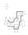
フェイスモードにおいては、図3に示されるように、フラップ12の板部材が延びる方向が、鉛直方向に対して60度を成すような状態とされる。このとき、フラップ12とコアンダ壁113との間に形成される流路が狭くなるので、当該流路を通過する空気の流速は大きくなる。つまり、コアンダ壁113の内面、すなわちコアンダ面113aに沿って高速気流が形成された状態となる。
In the face mode, as shown in FIG. 3, the direction in which the plate member of the
本発明者らが行った検証によれば、壁面に沿って流れる空気の流速が大きくなる程、当該空気の流れ方向が壁面に沿って変化する傾向は強くなることが判っている。つまり、空気の流速が大きくなる程、所謂コアンダ効果が生じやすくなる。このため、図3に示されるような高速気流が形成された状態においては、主ケーシング11の内部(案内流路X)を上方に向かって流れる空気の多くはコアンダ面113aに沿ってその流れ方向を変化させ、乗員側、すなわち車両50の後方側に向かって吹き出されることとなる。このように、コアンダ面113aは、吹き出される空気の少なくとも一部を、コアンダ効果により車両50の後方側に向かうよう案内するものとして機能する。
According to the verification conducted by the present inventors, it has been found that the tendency that the flow direction of the air changes along the wall surface becomes stronger as the flow velocity of the air flowing along the wall surface increases. That is, as the air flow rate increases, the so-called Coanda effect is more likely to occur. For this reason, in a state where a high-speed airflow as shown in FIG. 3 is formed, most of the air flowing upward in the main casing 11 (guide channel X) flows along the
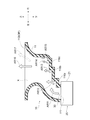
デフロストモードにおいては、図4に示されるように、フラップ12の板部材が延びる方向が、鉛直方向に対して45度を成すような状態とされる。このとき、フラップ12とコアンダ壁113との間に形成される流路が広くなるので、当該流路を通過する空気の流速は小さくなる。つまり、図3に示されるような高速気流は形成されず、コアンダ面113aに沿って流れる空気の流速が小さくなる。
In the defrost mode, as shown in FIG. 4, the direction in which the plate member of the
その結果、図4に示される状態においては、主ケーシング11の内部(案内流路X)を上方に向かって流れる空気は、コアンダ面113aに沿ってその流れ方向を殆ど変化させることなく、上方側に向かって、すなわちフロントガラス2に向かって吹き出されることとなる。
As a result, in the state shown in FIG. 4, the air flowing upward in the main casing 11 (guide flow path X) moves upward along the
循環風モードにおいては、フラップ12の板部材が延びる方向が鉛直方向に対してなす角度は、45度よりも大きく且つ60度よりも小さな角度となるように調整される。
In the circulating air mode, the angle formed by the direction in which the plate member of the
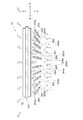
図5を参照しながら、ルーバ261a〜270aの構成について説明する。ルーバ261a〜270aは、案内流路Xのうちフラップ12よりも上流側となる位置において、開口OPの延びる方向に沿って一例に並んで配置されている。ルーバ261a〜270aは、出口部112から吹き出される空気の、左右方向における広がりを調整するための機構である。
The configuration of the
ルーバ261a〜270aのそれぞれは、2枚の平板部材を有している。それら板部材の各々は、主ケーシング11の内部の案内流路Xにおいて、ルーバシャフト261〜270の長手方向の殆どの部分から、ルーバシャフト261〜270の回転中心から離れるように、延びている。また、これら2枚の板部材は、ルーバシャフト261〜270に固定され、ルーバシャフト261〜270を中心として互いに対称的に延びている。このように構成されたルーバ261a〜270aは、ルーバシャフト261〜270と同軸かつ一体的に前後方向を軸として回転する。
Each of
図5に示される状態においては、ルーバ261a〜270aのそれぞれの傾斜角度は、吹き出される空気が左右方向に広がるような角度となっている。駆動機構14により、ルーバ261a〜270aのそれぞれの角度を個別に変化させることが可能となっている。このようなルーバ261a等の角度調整を実現するための具体的な構成については図示を省略するが、例えばルーバ毎に個別のモータを設けたり、ギヤの減速比をルーバ毎に異ならせたりする等、既知の構成を組み合わせることにより実現可能である。
In the state shown in FIG. 5, the inclination angles of the
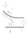
図6を参照しながら、主ケーシング11の内部における空気の流れについて説明する。図6においては、当該空気の流れが矢印AR1等により示されている。図6においては、フラップ12及びルーバ261a〜270aの図示が省略されている。
The flow of air in the
入口部111から案内流路X内に流入した空気は、矢印AR1で示されるように、車両の前方側に向かって流れる。その後は、既に述べたように、空気は下流側に行くに従って流れ方向を上方側に向けて変化させて行き、最終的には上方側に向かいながら出口部112に到達する。
The air that has flowed into the guide channel X from the
案内流路Xは、その全体が屈曲した流路として形成されている。案内流路Xを流れた空気が出口部112から吹き出される際においては、上記屈曲の影響により、空気の吹き出し方向が車両前方側に向かって傾斜してしまう傾向がある。つまり、空気の吹き出し方向が、屈曲した流路の外周側となる方向に偏ってしまう傾向がある。図6においては、このような空気の流れが点線の矢印AR7で示されている。このように、空気の吹き出し方向が偏ってしまうと、フラップ12やルーバ261a〜270aによる吹き出し方向の調整がうまくいかず、設計通りの位置に空気が吹き出されない可能性がある。
The guide channel X is formed as a channel that is bent as a whole. When the air flowing through the guide channel X is blown out from the
そこで、本実施形態では、案内流路Xの途中に衝突面115a、115b、115cを形成することで、上記のような吹き出し方向の偏りを抑制している。本実施形態では、主ケーシング11の壁面に沿って流れている一部の空気は衝突面115aに衝突して、その流れ方向を変化させる。具体的には、壁面(主ケーシング11の内面)から離れて上方側、すなわち出口部112側に向かうようにその流れ方向を変化させる。図6では、このような空気の流れが矢印AR2で示されている。
Therefore, in the present embodiment, by forming the
その下流側においても同様に、主ケーシング11の壁面に沿って流れている一部の空気は衝突面115bに衝突して、その流れ方向を変化させる。ここでも、空気は壁面から離れて上方側、すなわち出口部112側に向かうようにその流れ方向を変化させる。図6では、このような空気の流れが矢印AR3で示されている。
Similarly, on the downstream side, a part of the air flowing along the wall surface of the
その更に下流側においても同様であって、主ケーシング11の壁面に沿って流れている一部の空気は衝突面115cに衝突して、その流れ方向を変化させる。ここでも、空気は壁面から離れて上方側、すなわち出口部112側に向かうようにその流れ方向を変化させる。図6では、このような空気の流れが矢印AR4で示されている。
The same applies to the further downstream side, and a part of the air flowing along the wall surface of the
空気の一部は、衝突面115cよりも更に前方側に向かって進み、前方側端部の壁面に沿って上昇する。図6では、このような空気の流れが矢印AR5で示されている。
Part of the air travels further forward than the
以上のように、本実施形態では、屈曲形成された流路である案内流路Xの途中において、衝突面115a、115b、115cのそれぞれによって空気の流れ方向が上方側へと変更される。その結果、フラップ12やルーバ261a〜270aの影響が仮に無いものとしたときには、出口部112を通過する際における空気の流れ方向は、(矢印AR7で示されるものとは異なり)開口OPに対して概ね垂直な方向となる。図6では、このような空気の流れが矢印AR6で示されている。このように、衝突面115a、115b、115cは「方向変更部」として機能する。
As described above, in the present embodiment, the air flow direction is changed to the upper side by each of the
案内流路Xが屈曲していることの影響が低減され、開口OPに対して概ね垂直な方向に沿って空気が流れるので、フラップ12やルーバ261a〜270aによる吹き出し方向の調整を適切に行うことが可能となる。
Since the influence of the bending of the guide channel X is reduced and air flows along a direction substantially perpendicular to the opening OP, the blowing direction by the
本実施形態では、衝突面115a、115b、115cのそれぞれの突出量(段差の高さともいえる)のうち、衝突面115aの突出量が最も大きくなっており、衝突面115cの突出力が最も小さくなっている。つまり、空気の流れに沿って下流側に行くほど、衝突面の突出量が小さくなるように構成されている。
In the present embodiment, the amount of protrusion of the
このため、風量及び風速が比較的大きな上流側においては大きな衝突面115aによって空気の流れ方向が変更され、風量及び風速が比較的小さな下流側においては小さな衝突面115cによって空気の流れ方向が変更される。その結果、壁面に沿って流れる空気と、衝突面115aにより流れ方向を変化させる空気とのバランスが、案内流路Xの各部において適切に維持される。
Therefore, the air flow direction is changed by the
図6では、コアンダ面113aの上流側端部(下端部)の位置が点線DL1で示されている。本実施形態では、3つの方向変更部のうち最も上流側に形成されている衝突面115aが、前後方向において点線DL1よりも車両50の後方側となる位置に形成されている。このため、衝突面115aに衝突した空気は、衝突面115aから上方側に向かって進行した後、主ケーシング11の天井面117に衝突することとなる。本発明者らが行った検証によれば、コアンダ面113aに到達する前において一部の空気を天井面117に衝突させれば、その下流側のコアンダ面113aに沿った空気の流量が十分に確保されるという知見が得られている。
In FIG. 6, the position of the upstream end (lower end) of the
また、図6では、開口OPの前方側端部の位置が点線DL2で示されている。本実施形態では、3つの方向変更部のうち最も下流側に形成されている衝突面115cが、前後方向において点線DL2よりも車両50の前方側、すなわち開口OPよりも前方側となる位置に形成されている。このため、衝突面115cに衝突した空気は、衝突面115cから上方側に向かって進行した後、主ケーシング11の天井面118に対して概ね垂直に衝突することとなる。本発明者らが行った検証によれば、天井面118のうち広い範囲に空気を垂直に衝突させると、空気の流れ方向が滑らかに変化し、その際におけるエネルギーロスが少なくなるという知見が得られている。その結果、下流側における空気の流れ方向の偏りを更に抑制することができる。
In FIG. 6, the position of the front end portion of the opening OP is indicated by a dotted line DL2. In the present embodiment, the
以上のように、本実施形態では、コアンダ面113aや開口OPに対する衝突面115a等の位置を適切に調整することで、空気の流れ方向の偏りを更に抑制し、フラップ12やルーバ261a〜270aによる吹き出し方向の調整をより適切に行えるような構成となっている。
As described above, in the present embodiment, by appropriately adjusting the positions of the
図7を参照しながら、車両用空気吹き出し装置10の変形例について説明する。この変形例では、空調装置20の位置が、出口部112に対して左側にオフセットした位置となっている。このため、入口部111から空気が流入する方向に沿って見たときにおいて、出口部112は、入口部111の位置に対して右側にずれた位置に設けられている。また、主ケーシング11の内部に形成された案内流路Xは、その全体が屈曲した流路となっている。空調装置20のデフロスタ/フェイス開口部30から出た空調風は、上方側に向かって主ケーシング11の内部に流入した後、車両50の右側に向かってその流れ方向を変える。更にその後、下流側に行くに従って流れ方向を上方側に向けて変化させて行き、最終的には上方側に向かいながら出口部112に到達する。
A modification of the vehicle
図7に示されるように、主ケーシング11のうち下方側の部分、具体的には、屈曲した案内流路Xの外周側を区画している部分において、主ケーシング11の内壁の一部が階段状となっている。それぞれの段差部分(空気の流れ方向に対して垂直な部分)には衝突面116a、116b、116cが形成されている。
As shown in FIG. 7, a part of the inner wall of the
このような衝突面116a、116b、116cは、案内流路Xを区画する壁面の一部を内側に向けて突出させたもの、ということもできる。このため、衝突面115a、115b、115cのそれぞれは、案内流路Xを空気が流れる方向に対して概ね垂直な面となっている。衝突面116a、116b、116cは、空気の流れ方向に沿って、上流側からこの順に並ぶように配置されている。
It can also be said that
図7においては、当該空気の流れが矢印AR11等により示されている。この変形例においても、主ケーシング11の内部にはフラップ12及びルーバ261a〜270aが配置されているのであるが、図7においてはこれらの図示が省略されている。
In FIG. 7, the flow of the air is indicated by an arrow AR11 or the like. Also in this modified example, the
入口部111から案内流路X内に流入した空気は、矢印AR11で示されるように、車両の右側に向かって流れる。その後は、既に述べたように、空気は下流側に行くに従って流れ方向を上方側に向けて変化させて行き、最終的には上方側に向かいながら出口部112に到達する。
The air that flows into the guide channel X from the
案内流路Xは、その全体が屈曲した流路として形成されている。案内流路Xを流れた空気が出口部112から吹き出される際においては、上記屈曲の影響により、空気の吹き出し方向が車両右側に向かって傾斜してしまう傾向がある。つまり、空気の吹き出し方向が、屈曲した流路の外周側となる方向に偏ってしまう傾向がある。図7においては、このような空気の流れが点線の矢印AR17で示されている。このように、空気の吹き出し方向が偏ってしまうと、フラップ12やルーバ261a〜270aによる吹き出し方向の調整がうまくいかず、設計通りの位置に空気が吹き出されない可能性がある。
The guide channel X is formed as a channel that is bent as a whole. When the air flowing through the guide channel X is blown out from the
そこで、この変形例では、案内流路Xの途中に衝突面116a、116b、116cを形成することで、上記のような吹き出し方向の偏りを抑制している。この変形例では、主ケーシング11の壁面に沿って流れている一部の空気は衝突面116aに衝突して、その流れ方向を変化させる。具体的には、壁面(主ケーシング11の内面)から離れて上方側、すなわち出口部112側に向かうようにその流れ方向を変化させる。図7では、このような空気の流れが矢印AR12で示されている。
Therefore, in this modification, the
その下流側においても同様に、主ケーシング11の壁面に沿って流れている一部の空気は衝突面116bに衝突して、その流れ方向を変化させる。ここでも、空気は壁面から離れて上方側、すなわち出口部112側に向かうようにその流れ方向を変化させる。図7では、このような空気の流れが矢印AR13で示されている。
Similarly, on the downstream side, a part of the air flowing along the wall surface of the
その更に下流側においても同様であって、主ケーシング11の壁面に沿って流れている一部の空気は衝突面116cに衝突して、その流れ方向を変化させる。ここでも、空気は壁面から離れて上方側、すなわち出口部112側に向かうようにその流れ方向を変化させる。図7では、このような空気の流れが矢印AR14で示されている。
The same applies to the further downstream side, and a part of the air flowing along the wall surface of the
空気の一部は、衝突面116cよりも更に右側に向かって進み、右側端部の壁面に沿って上昇する。図7では、このような空気の流れが矢印AR15で示されている。
Part of the air travels further to the right side than the
以上のように、この変形例では、屈曲形成された流路である案内流路Xの途中において、衝突面116a、116b、116cのそれぞれによって空気の流れ方向が上方側へと変更される。その結果、フラップ12やルーバ261a〜270aの影響が仮に無いものとしたときには、出口部112を通過する際における空気の流れ方向は、(矢印AR17で示されるものとは異なり)開口OPに対して概ね垂直な方向となる。図7では、このような空気の流れが矢印AR16で示されている。このように、衝突面116a、116b、116cは「方向変更部」として機能する。
As described above, in this modification, the air flow direction is changed to the upper side by the
この変形例においても、案内流路Xが屈曲していることの影響が低減され、開口OPに対して概ね垂直な方向に沿って空気が流れるので、フラップ12やルーバ261a〜270aによる吹き出し方向の調整を適切に行うことが可能となる。
Also in this modified example, the influence of the bending of the guide channel X is reduced, and air flows along a direction substantially perpendicular to the opening OP, so that the direction of the blowing by the
この変形例では、衝突面116a、116b、116cのそれぞれの突出量(段差の高さともいえる)のうち、衝突面116aの突出量が最も大きくなっており、衝突面116cの突出力が最も小さくなっている。つまり、空気の流れに沿って下流側に行くほど、衝突面の突出量が小さくなるように構成されている。
In this modification, the amount of protrusion of the
このため、風量及び風速が比較的大きな上流側においては大きな衝突面116aによって空気の流れ方向が変更され、風量及び風速が比較的小さな下流側においては小さな衝突面116cによって空気の流れ方向が変更される。その結果、壁面に沿って流れる空気と、衝突面116aにより流れ方向を変化させる空気とのバランスが、案内流路Xの各部において適切に維持される。
Therefore, the air flow direction is changed by the
以上の説明においては、図7の構成は、図6等に示される本実施形態の変形例として説明した。しかしながら、図7の構成は図6の構成に替えて実施してもよいのであるが、図6の構成と共に実施することもできる。 In the above description, the configuration of FIG. 7 has been described as a modification of the present embodiment shown in FIG. However, although the configuration of FIG. 7 may be implemented in place of the configuration of FIG. 6, it can also be implemented with the configuration of FIG.
つまり、空調装置20(及び入口部111)の位置が、例えば出口部112に対して左側にオフセットし且つ後方側にもオフセットした位置となっている場合において、主ケーシング11が、図6の衝突面115a、115b、115cと、図7の衝突面116a、116b、116cと、の全てを有しているような構成としてもよい。
That is, when the position of the air conditioner 20 (and the inlet portion 111) is, for example, a position that is offset to the left side and offset to the rear side with respect to the
以上においては、主ケーシング11の一部を階段状とすることによって衝突面115a,115b,115c,116a,116b,116cを形成し、これらを方向変更部として機能させる構成について説明した。しかしながら、方向変更部は、上記以外の態様により構成されていてもよい。例えば、主ケーシング11とは別の部材を方向変更部として案内流路X内に配置し、当該部材によって空気の流れ方向を入口部111へと変化させるような態様としてもよい。
In the above description, the configuration has been described in which the
以上、具体例を参照しつつ本発明の実施の形態について説明した。しかし、本発明はこれらの具体例に限定されるものではない。すなわち、これら具体例に、当業者が適宜設計変更を加えたものも、本発明の特徴を備えている限り、本発明の範囲に包含される。例えば、前述した各具体例が備える各要素およびその配置、材料、条件、形状、サイズなどは、例示したものに限定されるわけではなく適宜変更することができる。また、前述した各実施の形態が備える各要素は、技術的に可能な限りにおいて組み合わせることができ、これらを組み合わせたものも本発明の特徴を含む限り本発明の範囲に包含される。 The embodiments of the present invention have been described above with reference to specific examples. However, the present invention is not limited to these specific examples. In other words, those specific examples that have been appropriately modified by those skilled in the art are also included in the scope of the present invention as long as they have the characteristics of the present invention. For example, the elements included in each of the specific examples described above and their arrangement, materials, conditions, shapes, sizes, and the like are not limited to those illustrated, but can be changed as appropriate. Moreover, each element with which each embodiment mentioned above is provided can be combined as long as technically possible, and the combination of these is also included in the scope of the present invention as long as it includes the features of the present invention.
50:車両
10:車両用空気吹き出し装置
11: 主ケーシング
111:入口部
112:出口部
113a:コアンダ面
115a,115b,115c,116a,116b,116c:衝突面
X:案内流路
20:空調装置
50: Vehicle 10: Vehicle air blowing device 11: Main casing 111: Inlet portion 112:
Claims (6)
前記空調装置から空気が流入する部分である入口部(111)と、
前記車両の車室内に空気が吹き出る部分である出口部(112)と、
前記入口部に流入した空気を、前記出口部まで案内する案内流路(X)を区画する流路壁(11)と、を備え、
前記入口部から空気が流入する方向に沿って見たときにおいて、前記出口部は、前記入口部の位置に対してずれた位置に設けられており、
前記流路壁には、
前記流路壁の内面に沿って流れる空気の一部を、前記流路壁から離れて前記出口部側へと向かうように案内する方向変更部(115a,115b,115c,116a,116b,116c)が形成されている、車両用空気吹き出し装置。 A vehicle air blowing device (10) mounted on a vehicle (50) together with an air conditioner (20),
An inlet part (111) which is a part into which air flows from the air conditioner;
An exit portion (112) which is a portion where air blows into the vehicle interior of the vehicle;
A flow path wall (11) defining a guide flow path (X) for guiding the air flowing into the inlet section to the outlet section,
When viewed along the direction in which air flows from the inlet portion, the outlet portion is provided at a position shifted from the position of the inlet portion,
In the channel wall,
Direction changing parts (115a, 115b, 115c, 116a, 116b, 116c) for guiding a part of the air flowing along the inner surface of the flow path wall away from the flow path wall toward the outlet side. The air blowing device for vehicles in which is formed.
空気の流れに沿って下流側に行くほど、前記衝突面の突出量が小さくなる、請求項2に記載の車両用空気吹き出し装置。 Each of the direction changing portions has a collision surface (115a, 115b, 115c, 116a, 116b, 116c) formed so as to protrude from the flow channel wall toward the inside of the guide flow channel and to collide with air. And
The vehicle air blowing device according to claim 2, wherein the amount of protrusion of the collision surface decreases as it goes downstream along the air flow.
前記流路壁のうち最も下流側の部分には、前記開口から吹き出される空気の少なくとも一部を、コアンダ効果により前記車両の後方側に向かうよう案内するコアンダ面(113a)が形成されており、
複数の前記方向変更部のうち最も上流側に形成されているものは、
上面視において、前記コアンダ面の上流側端部よりも前記車両の後方側となる位置に形成されている、請求項2に記載の車両用空気吹き出し装置。 In the outlet portion, an opening (OP) for blowing out air is formed upward,
A Coanda surface (113a) that guides at least a part of the air blown from the opening to the rear side of the vehicle by the Coanda effect is formed in the most downstream portion of the flow path wall. ,
What is formed on the most upstream side among the plurality of direction change parts,
The vehicle air blowing device according to claim 2, wherein the air blowing device for a vehicle according to claim 2 is formed at a position on the rear side of the vehicle with respect to an upstream side end portion of the Coanda surface in a top view.
複数の前記方向変更部のうち最も下流側に形成されているものは、
上面視において、前記開口よりも前記車両の前方側となる位置に形成されている、請求項2に記載の車両用空気吹き出し装置。 In the outlet portion, an opening (OP) for blowing out air is formed upward,
What is formed on the most downstream side among the plurality of direction change portions,
The vehicle air blowing device according to claim 2, wherein the air blowing device for a vehicle is formed at a position closer to the front side of the vehicle than the opening in a top view.
Priority Applications (1)
| Application Number | Priority Date | Filing Date | Title |
|---|---|---|---|
| JP2016034312A JP6540542B2 (en) | 2016-02-25 | 2016-02-25 | Vehicle air blowing device |
Applications Claiming Priority (1)
| Application Number | Priority Date | Filing Date | Title |
|---|---|---|---|
| JP2016034312A JP6540542B2 (en) | 2016-02-25 | 2016-02-25 | Vehicle air blowing device |
Publications (2)
| Publication Number | Publication Date |
|---|---|
| JP2017149308A true JP2017149308A (en) | 2017-08-31 |
| JP6540542B2 JP6540542B2 (en) | 2019-07-10 |
Family
ID=59738801
Family Applications (1)
| Application Number | Title | Priority Date | Filing Date |
|---|---|---|---|
| JP2016034312A Expired - Fee Related JP6540542B2 (en) | 2016-02-25 | 2016-02-25 | Vehicle air blowing device |
Country Status (1)
| Country | Link |
|---|---|
| JP (1) | JP6540542B2 (en) |
Cited By (1)
| Publication number | Priority date | Publication date | Assignee | Title |
|---|---|---|---|---|
| WO2021121460A1 (en) * | 2019-12-20 | 2021-06-24 | Gentherm Gmbh | Ventilation device for a cabin of a vehicle |
Citations (7)
| Publication number | Priority date | Publication date | Assignee | Title |
|---|---|---|---|---|
| JPS5912752U (en) * | 1982-07-16 | 1984-01-26 | 日産自動車株式会社 | Vehicle defroster device |
| JPS60169320A (en) * | 1984-02-14 | 1985-09-02 | Nippon Plast Co Ltd | Ventilator for vehicle |
| JPH0848128A (en) * | 1994-05-31 | 1996-02-20 | Nippondenso Co Ltd | Automotive air conditioner |
| JPH10230733A (en) * | 1997-02-20 | 1998-09-02 | Denso Corp | Vehicle air conditioner |
| US20040144521A1 (en) * | 2003-01-23 | 2004-07-29 | Farag Ashraf A | Casing for a heat exchange system |
| JP2005059807A (en) * | 2003-08-20 | 2005-03-10 | Denso Corp | Air conditioner for vehicles |
| JP2014210564A (en) * | 2013-04-05 | 2014-11-13 | 株式会社デンソー | Air blower |
-
2016
- 2016-02-25 JP JP2016034312A patent/JP6540542B2/en not_active Expired - Fee Related
Patent Citations (7)
| Publication number | Priority date | Publication date | Assignee | Title |
|---|---|---|---|---|
| JPS5912752U (en) * | 1982-07-16 | 1984-01-26 | 日産自動車株式会社 | Vehicle defroster device |
| JPS60169320A (en) * | 1984-02-14 | 1985-09-02 | Nippon Plast Co Ltd | Ventilator for vehicle |
| JPH0848128A (en) * | 1994-05-31 | 1996-02-20 | Nippondenso Co Ltd | Automotive air conditioner |
| JPH10230733A (en) * | 1997-02-20 | 1998-09-02 | Denso Corp | Vehicle air conditioner |
| US20040144521A1 (en) * | 2003-01-23 | 2004-07-29 | Farag Ashraf A | Casing for a heat exchange system |
| JP2005059807A (en) * | 2003-08-20 | 2005-03-10 | Denso Corp | Air conditioner for vehicles |
| JP2014210564A (en) * | 2013-04-05 | 2014-11-13 | 株式会社デンソー | Air blower |
Cited By (1)
| Publication number | Priority date | Publication date | Assignee | Title |
|---|---|---|---|---|
| WO2021121460A1 (en) * | 2019-12-20 | 2021-06-24 | Gentherm Gmbh | Ventilation device for a cabin of a vehicle |
Also Published As
| Publication number | Publication date |
|---|---|
| JP6540542B2 (en) | 2019-07-10 |
Similar Documents
| Publication | Publication Date | Title |
|---|---|---|
| US20130319630A1 (en) | Vehicular air-conditioning system | |
| JP4424409B2 (en) | Air conditioner for vehicles | |
| CN105189162B (en) | air blower | |
| KR20140116157A (en) | Vehicle air conditioning device | |
| CN109803843B (en) | Air conditioning unit for vehicle | |
| CN104619531B (en) | Vehicular air conditioning device | |
| JP6734641B2 (en) | Vehicle air conditioner | |
| JP2017149307A (en) | Air blowout device for vehicle | |
| JP5131141B2 (en) | Air conditioner for vehicles | |
| JP2010018248A (en) | Air conditioner for vehicle | |
| JP4830771B2 (en) | Air conditioner for vehicles | |
| JP5924230B2 (en) | Air conditioner | |
| JP6547656B2 (en) | Vehicle air blowing device | |
| WO2015115058A1 (en) | Air conditioning device for vehicle | |
| JP2008094251A (en) | Air conditioner for vehicles | |
| JP6540542B2 (en) | Vehicle air blowing device | |
| JP6658080B2 (en) | Air blowing device for vehicles | |
| JP6565739B2 (en) | Air blowing device for vehicle | |
| JP6399211B2 (en) | Air blowing device | |
| JP6481595B2 (en) | Air blowing device for vehicle | |
| JP6481631B2 (en) | Air blowing device for vehicle | |
| JP2017100553A (en) | Air blowout device for vehicle | |
| JP4524939B2 (en) | Air passage opening and closing device and vehicle air conditioner | |
| JP3997959B2 (en) | Air conditioner for vehicles | |
| JP2017149302A (en) | Air blowout device for vehicle |
Legal Events
| Date | Code | Title | Description |
|---|---|---|---|
| A621 | Written request for application examination |
Free format text: JAPANESE INTERMEDIATE CODE: A621 Effective date: 20180529 |
|
| A977 | Report on retrieval |
Free format text: JAPANESE INTERMEDIATE CODE: A971007 Effective date: 20190228 |
|
| A131 | Notification of reasons for refusal |
Free format text: JAPANESE INTERMEDIATE CODE: A131 Effective date: 20190305 |
|
| A521 | Request for written amendment filed |
Free format text: JAPANESE INTERMEDIATE CODE: A523 Effective date: 20190411 |
|
| TRDD | Decision of grant or rejection written | ||
| A01 | Written decision to grant a patent or to grant a registration (utility model) |
Free format text: JAPANESE INTERMEDIATE CODE: A01 Effective date: 20190514 |
|
| A61 | First payment of annual fees (during grant procedure) |
Free format text: JAPANESE INTERMEDIATE CODE: A61 Effective date: 20190527 |
|
| R151 | Written notification of patent or utility model registration |
Ref document number: 6540542 Country of ref document: JP Free format text: JAPANESE INTERMEDIATE CODE: R151 |
|
| LAPS | Cancellation because of no payment of annual fees |