JP2017149380A - Resin rear window and resin window - Google Patents
Resin rear window and resin window Download PDFInfo
- Publication number
- JP2017149380A JP2017149380A JP2016036031A JP2016036031A JP2017149380A JP 2017149380 A JP2017149380 A JP 2017149380A JP 2016036031 A JP2016036031 A JP 2016036031A JP 2016036031 A JP2016036031 A JP 2016036031A JP 2017149380 A JP2017149380 A JP 2017149380A
- Authority
- JP
- Japan
- Prior art keywords
- resin
- rear window
- substrate
- resin base
- flexible substrate
- Prior art date
- Legal status (The legal status is an assumption and is not a legal conclusion. Google has not performed a legal analysis and makes no representation as to the accuracy of the status listed.)
- Pending
Links
- 229920005989 resin Polymers 0.000 title claims abstract description 386
- 239000011347 resin Substances 0.000 title claims abstract description 386
- 239000000758 substrate Substances 0.000 claims abstract description 192
- 239000004020 conductor Substances 0.000 claims description 34
- 230000002093 peripheral effect Effects 0.000 claims description 22
- 238000007747 plating Methods 0.000 claims description 12
- 229920001721 polyimide Polymers 0.000 claims description 9
- 239000004642 Polyimide Substances 0.000 claims description 8
- 229920003229 poly(methyl methacrylate) Polymers 0.000 claims description 6
- 229920000515 polycarbonate Polymers 0.000 claims description 6
- 239000004417 polycarbonate Substances 0.000 claims description 6
- 239000004926 polymethyl methacrylate Substances 0.000 claims description 6
- 239000010410 layer Substances 0.000 description 137
- 238000000034 method Methods 0.000 description 44
- 239000000919 ceramic Substances 0.000 description 40
- 239000000463 material Substances 0.000 description 37
- 239000011521 glass Substances 0.000 description 14
- PXHVJJICTQNCMI-UHFFFAOYSA-N nickel Substances [Ni] PXHVJJICTQNCMI-UHFFFAOYSA-N 0.000 description 14
- 238000005240 physical vapour deposition Methods 0.000 description 11
- 238000004544 sputter deposition Methods 0.000 description 10
- 239000004925 Acrylic resin Substances 0.000 description 8
- 229920000178 Acrylic resin Polymers 0.000 description 8
- -1 polyethylene Polymers 0.000 description 7
- 229910004298 SiO 2 Inorganic materials 0.000 description 6
- 229910052751 metal Inorganic materials 0.000 description 6
- 239000002184 metal Substances 0.000 description 6
- 230000003746 surface roughness Effects 0.000 description 6
- BQCADISMDOOEFD-UHFFFAOYSA-N Silver Chemical compound [Ag] BQCADISMDOOEFD-UHFFFAOYSA-N 0.000 description 5
- 230000015572 biosynthetic process Effects 0.000 description 5
- 238000005268 plasma chemical vapour deposition Methods 0.000 description 5
- 229910052709 silver Inorganic materials 0.000 description 5
- 239000004332 silver Substances 0.000 description 5
- 238000007641 inkjet printing Methods 0.000 description 4
- 238000001755 magnetron sputter deposition Methods 0.000 description 4
- 238000007650 screen-printing Methods 0.000 description 4
- 238000005476 soldering Methods 0.000 description 4
- NIXOWILDQLNWCW-UHFFFAOYSA-M Acrylate Chemical compound [O-]C(=O)C=C NIXOWILDQLNWCW-UHFFFAOYSA-M 0.000 description 3
- RYGMFSIKBFXOCR-UHFFFAOYSA-N Copper Chemical compound [Cu] RYGMFSIKBFXOCR-UHFFFAOYSA-N 0.000 description 3
- VYPSYNLAJGMNEJ-UHFFFAOYSA-N Silicium dioxide Chemical compound O=[Si]=O VYPSYNLAJGMNEJ-UHFFFAOYSA-N 0.000 description 3
- 239000002390 adhesive tape Substances 0.000 description 3
- 238000004140 cleaning Methods 0.000 description 3
- 238000000576 coating method Methods 0.000 description 3
- 229910052802 copper Inorganic materials 0.000 description 3
- 239000010949 copper Substances 0.000 description 3
- 238000001723 curing Methods 0.000 description 3
- 230000000694 effects Effects 0.000 description 3
- 238000005530 etching Methods 0.000 description 3
- 239000011888 foil Substances 0.000 description 3
- 238000004519 manufacturing process Methods 0.000 description 3
- 239000000203 mixture Substances 0.000 description 3
- 229910052759 nickel Inorganic materials 0.000 description 3
- 229920002050 silicone resin Polymers 0.000 description 3
- 229910000838 Al alloy Inorganic materials 0.000 description 2
- XEEYBQQBJWHFJM-UHFFFAOYSA-N Iron Chemical compound [Fe] XEEYBQQBJWHFJM-UHFFFAOYSA-N 0.000 description 2
- 229920000877 Melamine resin Polymers 0.000 description 2
- 239000004640 Melamine resin Substances 0.000 description 2
- ZOKXTWBITQBERF-UHFFFAOYSA-N Molybdenum Chemical compound [Mo] ZOKXTWBITQBERF-UHFFFAOYSA-N 0.000 description 2
- 125000003647 acryloyl group Chemical group O=C([*])C([H])=C([H])[H] 0.000 description 2
- 229910045601 alloy Inorganic materials 0.000 description 2
- 239000000956 alloy Substances 0.000 description 2
- QVGXLLKOCUKJST-UHFFFAOYSA-N atomic oxygen Chemical compound [O] QVGXLLKOCUKJST-UHFFFAOYSA-N 0.000 description 2
- 238000003618 dip coating Methods 0.000 description 2
- 239000003822 epoxy resin Substances 0.000 description 2
- 230000020169 heat generation Effects 0.000 description 2
- 229910003437 indium oxide Inorganic materials 0.000 description 2
- PJXISJQVUVHSOJ-UHFFFAOYSA-N indium(iii) oxide Chemical compound [O-2].[O-2].[O-2].[In+3].[In+3] PJXISJQVUVHSOJ-UHFFFAOYSA-N 0.000 description 2
- 229910010272 inorganic material Inorganic materials 0.000 description 2
- 239000011147 inorganic material Substances 0.000 description 2
- WABPQHHGFIMREM-UHFFFAOYSA-N lead(0) Chemical compound [Pb] WABPQHHGFIMREM-UHFFFAOYSA-N 0.000 description 2
- 229910052750 molybdenum Inorganic materials 0.000 description 2
- 239000011733 molybdenum Substances 0.000 description 2
- 229910000623 nickel–chromium alloy Inorganic materials 0.000 description 2
- 239000001301 oxygen Substances 0.000 description 2
- 229910052760 oxygen Inorganic materials 0.000 description 2
- 230000035515 penetration Effects 0.000 description 2
- 229920002037 poly(vinyl butyral) polymer Polymers 0.000 description 2
- 229920000647 polyepoxide Polymers 0.000 description 2
- 239000005020 polyethylene terephthalate Substances 0.000 description 2
- 229920000139 polyethylene terephthalate Polymers 0.000 description 2
- 238000007788 roughening Methods 0.000 description 2
- 239000002356 single layer Substances 0.000 description 2
- 238000005507 spraying Methods 0.000 description 2
- 229910052715 tantalum Inorganic materials 0.000 description 2
- GUVRBAGPIYLISA-UHFFFAOYSA-N tantalum atom Chemical compound [Ta] GUVRBAGPIYLISA-UHFFFAOYSA-N 0.000 description 2
- 229920002803 thermoplastic polyurethane Polymers 0.000 description 2
- WFKWXMTUELFFGS-UHFFFAOYSA-N tungsten Chemical compound [W] WFKWXMTUELFFGS-UHFFFAOYSA-N 0.000 description 2
- 229910052721 tungsten Inorganic materials 0.000 description 2
- 239000010937 tungsten Substances 0.000 description 2
- 238000005406 washing Methods 0.000 description 2
- JHPBZFOKBAGZBL-UHFFFAOYSA-N (3-hydroxy-2,2,4-trimethylpentyl) 2-methylprop-2-enoate Chemical compound CC(C)C(O)C(C)(C)COC(=O)C(C)=C JHPBZFOKBAGZBL-UHFFFAOYSA-N 0.000 description 1
- 229910018072 Al 2 O 3 Inorganic materials 0.000 description 1
- MYMOFIZGZYHOMD-UHFFFAOYSA-N Dioxygen Chemical compound O=O MYMOFIZGZYHOMD-UHFFFAOYSA-N 0.000 description 1
- 239000004593 Epoxy Substances 0.000 description 1
- LFQSCWFLJHTTHZ-UHFFFAOYSA-N Ethanol Chemical compound CCO LFQSCWFLJHTTHZ-UHFFFAOYSA-N 0.000 description 1
- 239000004698 Polyethylene Substances 0.000 description 1
- 239000004793 Polystyrene Substances 0.000 description 1
- 239000004372 Polyvinyl alcohol Substances 0.000 description 1
- 229910006404 SnO 2 Inorganic materials 0.000 description 1
- GWEVSGVZZGPLCZ-UHFFFAOYSA-N Titan oxide Chemical compound O=[Ti]=O GWEVSGVZZGPLCZ-UHFFFAOYSA-N 0.000 description 1
- XLOMVQKBTHCTTD-UHFFFAOYSA-N Zinc monoxide Chemical compound [Zn]=O XLOMVQKBTHCTTD-UHFFFAOYSA-N 0.000 description 1
- 150000001252 acrylic acid derivatives Chemical class 0.000 description 1
- 239000000853 adhesive Substances 0.000 description 1
- 230000001070 adhesive effect Effects 0.000 description 1
- 229910052782 aluminium Inorganic materials 0.000 description 1
- XAGFODPZIPBFFR-UHFFFAOYSA-N aluminium Chemical compound [Al] XAGFODPZIPBFFR-UHFFFAOYSA-N 0.000 description 1
- PNEYBMLMFCGWSK-UHFFFAOYSA-N aluminium oxide Inorganic materials [O-2].[O-2].[O-2].[Al+3].[Al+3] PNEYBMLMFCGWSK-UHFFFAOYSA-N 0.000 description 1
- 238000005452 bending Methods 0.000 description 1
- 239000011248 coating agent Substances 0.000 description 1
- 239000002131 composite material Substances 0.000 description 1
- 238000010276 construction Methods 0.000 description 1
- 230000006866 deterioration Effects 0.000 description 1
- 229910001882 dioxygen Inorganic materials 0.000 description 1
- 238000001810 electrochemical catalytic reforming Methods 0.000 description 1
- 238000001227 electron beam curing Methods 0.000 description 1
- 239000005357 flat glass Substances 0.000 description 1
- 239000007789 gas Substances 0.000 description 1
- 238000010438 heat treatment Methods 0.000 description 1
- 239000012535 impurity Substances 0.000 description 1
- 239000012212 insulator Substances 0.000 description 1
- 238000007737 ion beam deposition Methods 0.000 description 1
- 238000007733 ion plating Methods 0.000 description 1
- 238000001659 ion-beam spectroscopy Methods 0.000 description 1
- 229910052742 iron Inorganic materials 0.000 description 1
- 239000005340 laminated glass Substances 0.000 description 1
- 230000000873 masking effect Effects 0.000 description 1
- 230000008018 melting Effects 0.000 description 1
- 238000002844 melting Methods 0.000 description 1
- 150000002739 metals Chemical class 0.000 description 1
- 230000005012 migration Effects 0.000 description 1
- 238000013508 migration Methods 0.000 description 1
- 150000004767 nitrides Chemical class 0.000 description 1
- 239000011224 oxide ceramic Substances 0.000 description 1
- 229910052574 oxide ceramic Inorganic materials 0.000 description 1
- 229920003023 plastic Polymers 0.000 description 1
- 239000004033 plastic Substances 0.000 description 1
- 229920001225 polyester resin Polymers 0.000 description 1
- 239000004645 polyester resin Substances 0.000 description 1
- 229920000573 polyethylene Polymers 0.000 description 1
- 239000011112 polyethylene naphthalate Substances 0.000 description 1
- 229920000642 polymer Polymers 0.000 description 1
- 229920001296 polysiloxane Polymers 0.000 description 1
- 229920002451 polyvinyl alcohol Polymers 0.000 description 1
- 239000004800 polyvinyl chloride Substances 0.000 description 1
- 238000002360 preparation method Methods 0.000 description 1
- 238000007639 printing Methods 0.000 description 1
- 238000001552 radio frequency sputter deposition Methods 0.000 description 1
- 239000002994 raw material Substances 0.000 description 1
- 238000005546 reactive sputtering Methods 0.000 description 1
- 239000012779 reinforcing material Substances 0.000 description 1
- 239000000377 silicon dioxide Substances 0.000 description 1
- 229910000679 solder Inorganic materials 0.000 description 1
- 239000002904 solvent Substances 0.000 description 1
- 238000001029 thermal curing Methods 0.000 description 1
- 229920005992 thermoplastic resin Polymers 0.000 description 1
- XOLBLPGZBRYERU-UHFFFAOYSA-N tin dioxide Chemical compound O=[Sn]=O XOLBLPGZBRYERU-UHFFFAOYSA-N 0.000 description 1
- 229910001887 tin oxide Inorganic materials 0.000 description 1
- 239000012780 transparent material Substances 0.000 description 1
- 238000004506 ultrasonic cleaning Methods 0.000 description 1
- 238000001771 vacuum deposition Methods 0.000 description 1
- XLYOFNOQVPJJNP-UHFFFAOYSA-N water Substances O XLYOFNOQVPJJNP-UHFFFAOYSA-N 0.000 description 1
Images


Landscapes
- Laminated Bodies (AREA)
- Window Of Vehicle (AREA)
Abstract
Description
本発明は、樹脂製リアウインドウ及び樹脂製ウインドウに関する。 The present invention relates to a resin rear window and a resin window.
自動車用リアウインドウには、通電により発熱し、ガラスに発生した曇りを防止又は除去するための熱線が形成されている。 The rear window for an automobile generates heat when energized to prevent or remove fogging generated on the glass.
自動車用リアウインドウに形成された熱線を車両側の配線と接続するための構造として、例えば、特許文献1には、接続部として熱線プリントが形成されたガラス板と、該ガラス板に設けられ、上記熱線プリントに電気的に接続された導体と、上記熱線プリントに電気的に接続され、該熱線プリントを介して上記導体と電気的に接続されるリード線と、を有するウインドガラス構造が記載されている。 As a structure for connecting the heat ray formed in the rear window for automobiles to the wiring on the vehicle side, for example, in Patent Document 1, a glass plate on which a heat ray print is formed as a connection portion, and provided on the glass plate, A window glass structure having a conductor electrically connected to the heat ray print and a lead wire electrically connected to the heat ray print and electrically connected to the conductor via the heat ray print is described. ing.
特許文献1には、ガラス板に設けられる導体と、上記導体と接続されるリード線とは、それぞれ熱線プリントに半田付けされることにより電気的に接続されていることが記載されている。また、特許文献1には、上記ガラス板が、2枚のガラスの間に樹脂フィルム及び導体を挟み込んで接着した合わせガラスであってもよいことが記載されている。 Patent Document 1 describes that a conductor provided on a glass plate and a lead wire connected to the conductor are electrically connected to each other by soldering to a hot wire print. Patent Document 1 describes that the glass plate may be a laminated glass in which a resin film and a conductor are sandwiched and bonded between two glasses.
近年、自動車の軽量化を目的として、自動車用ウインドウに樹脂ガラスを用いることが検討されている。
しかし、樹脂ガラスを自動車用リアウインドウに用いる場合、樹脂製リアウインドウに熱線をどのように設けるか、及び、樹脂製リアウインドウに設けられた熱線を車両側の配線とどのように接続するかについては充分に検討されていない。
In recent years, the use of resin glass for automobile windows has been studied for the purpose of reducing the weight of automobiles.
However, when resin glass is used for an automobile rear window, how to provide heat rays to the resin rear window and how to connect the heat wires provided to the resin rear window to the wiring on the vehicle side Has not been fully studied.
例えば、特許文献1に記載のガラス構造を樹脂製リアウインドウに適用した場合、樹脂ガラスの材料であるポリカーボネート等は熱可塑性樹脂であるため、半田付けの際に樹脂ガラスが変形する等の問題が発生することが懸念される。 For example, when the glass structure described in Patent Document 1 is applied to a resin rear window, polycarbonate or the like, which is a resin glass material, is a thermoplastic resin, so that there is a problem that the resin glass is deformed during soldering. There are concerns about the occurrence.
本発明は、上記の問題を解決するためになされたものであり、車両側の配線との接続性に優れる熱線が設けられた樹脂製リアウインドウを提供することを目的とする。本発明はまた、車両側の配線との接続性に優れる導体が設けられた樹脂製ウインドウを提供することを目的とする。 The present invention has been made to solve the above-described problems, and an object of the present invention is to provide a resin rear window provided with a heat ray excellent in connectivity with wiring on the vehicle side. Another object of the present invention is to provide a resin window provided with a conductor excellent in connectivity with wiring on the vehicle side.
本発明の樹脂製リアウインドウは、第1樹脂基体と、上記第1樹脂基体と対向するように配置された第2樹脂基体と、上記第1樹脂基体及び上記第2樹脂基体の間に配置された熱線、並びに、上記熱線と接続された給電用パッドと、上記給電用パッドと接続するための端子を備えるフレキシブル基板と、からなり、上記フレキシブル基板の一端は、上記端子が上記給電用パッドと接続されるように上記第1樹脂基体及び上記第2樹脂基体の間に挟持されており、上記フレキシブル基板の他端は、上記第1樹脂基体及び上記第2樹脂基体から外部に露出していることを特徴とする。 The resin rear window of the present invention is disposed between the first resin base, the second resin base disposed to face the first resin base, and the first resin base and the second resin base. And a flexible substrate including a terminal for connecting to the power supply pad, and one end of the flexible substrate is connected to the power supply pad. It is sandwiched between the first resin base and the second resin base so as to be connected, and the other end of the flexible substrate is exposed to the outside from the first resin base and the second resin base. It is characterized by that.
本発明の樹脂製リアウインドウでは、フレキシブル基板が2枚の樹脂基体の間に挟持されており、そのフレキシブル基板が、熱線と接続された給電用パッドと接続されている。したがって、フレキシブル基板を介して、樹脂製リアウインドウに設けられた熱線を車両側の配線と電気的に接続させることができる。 In the resin rear window of the present invention, a flexible substrate is sandwiched between two resin substrates, and the flexible substrate is connected to a power supply pad connected to a heat ray. Therefore, the heat wire provided in the resin rear window can be electrically connected to the vehicle-side wiring via the flexible substrate.
本発明の樹脂製リアウインドウでは、2枚の樹脂基体の間に挟持することによってフレキシブル基板が給電用パッドと接続されているため、特別な固定具を用いて両者を接続する必要もなく、また、半田や導電性ペースト等を用いて両者を接着させる必要もない。そのため、半田付けの熱によって樹脂基体が変形するという問題、及び、導電性ペーストの劣化やマイグレーションによって接続性が低下するという問題を防止することができる。 In the resin rear window of the present invention, since the flexible substrate is connected to the power feeding pad by being sandwiched between two resin bases, it is not necessary to connect the two using a special fixing tool. It is not necessary to bond the two using solder, conductive paste, or the like. Therefore, it is possible to prevent the problem that the resin substrate is deformed by the heat of soldering and the problem that the connectivity is deteriorated due to deterioration or migration of the conductive paste.
本発明の樹脂製リアウインドウにおいて、2枚の樹脂基体から外部に露出したフレキシブル基板は、屈曲性を有するため、折り畳む、引っ掛ける等の操作が可能となる。したがって、本発明の樹脂製リアウインドウを車体に組み付ける際には、例えば、フレキシブル基板を折り畳んでヒンジ内に収納する等といった操作も可能となる。 In the resin rear window of the present invention, the flexible substrate exposed to the outside from the two resin substrates has flexibility, so that operations such as folding and hooking are possible. Therefore, when the resin rear window of the present invention is assembled to the vehicle body, for example, an operation such as folding the flexible board and storing it in the hinge can be performed.
また、本発明の樹脂製リアウインドウでは、2枚の樹脂基体の間に熱線が配置されているため、熱線で発生した熱がリアウインドウの両面に均一に伝達されやすくなる。その結果、ムラのない防曇効果が得られる。 Moreover, in the resin rear window of the present invention, the heat rays are disposed between the two resin substrates, so that the heat generated by the heat rays is easily transmitted uniformly to both surfaces of the rear window. As a result, an anti-fogging effect without unevenness can be obtained.
さらに、本発明の樹脂製リアウインドウでは、フレキシブル基板と給電用パッドとの接続部が2枚の樹脂基体の間に位置しているため、接続部が振動等のダメージを受けにくく、振動等によって接続性が低下するという問題を防止することができる。 Furthermore, in the resin rear window of the present invention, since the connecting portion between the flexible substrate and the power feeding pad is located between the two resin bases, the connecting portion is not easily damaged by vibration or the like. It is possible to prevent the problem that the connectivity is lowered.
本発明の樹脂製リアウインドウにおいて、上記第1樹脂基体及び上記第2樹脂基体は、いずれも、ポリカーボネート又はポリメチルメタクリレートからなることが好ましい。
これらの樹脂は、高い透光性を有している上に、複屈折がなく、充分な強度を有しているため、樹脂基体の材料として好適に使用することができる。
In the resin rear window of the present invention, it is preferable that the first resin base and the second resin base are both made of polycarbonate or polymethyl methacrylate.
Since these resins have high translucency, do not have birefringence, and have sufficient strength, they can be suitably used as a resin substrate material.
本発明の樹脂製リアウインドウにおいて、上記フレキシブル基板は、ポリイミドからなることが好ましい。
ポリイミドは屈曲性に優れるため、フレキシブル基板の材料として好適に使用することができる。
In the resin rear window of the present invention, the flexible substrate is preferably made of polyimide.
Since polyimide is excellent in flexibility, it can be suitably used as a material for a flexible substrate.
本発明の樹脂製リアウインドウにおいて、上記給電用パッドの表面、及び、上記フレキシブル基板の端子の表面には、Ni/Auめっき層が設けられていることが好ましい。
給電用パッドの表面、及び、フレキシブル基板の端子の表面にNi/Auめっき層を設けることによって、給電用パッドとフレキシブル基板との電気的接続を確実に行うことができる。
In the resin rear window of the present invention, a Ni / Au plating layer is preferably provided on the surface of the power supply pad and the surface of the terminal of the flexible substrate.
By providing the Ni / Au plating layer on the surface of the power supply pad and the surface of the terminal of the flexible substrate, electrical connection between the power supply pad and the flexible substrate can be reliably performed.
本発明の樹脂製リアウインドウにおいて、上記第1樹脂基体の主面の面積は、上記第2樹脂基体の主面の面積よりも大きく、上記樹脂製リアウインドウの周縁部に上記樹脂製リアウインドウの中央部よりも薄い領域が存在することが好ましい。
通常、リアウインドウの周縁部は、マスキング用の黒色塗装等が施された不可視部となっている。そのため、運転時の視認性に影響しない周縁部を中央部よりも薄くすることによって、リアウインドウを軽量化することができる。
また、周縁部以外の中央部の厚さが一定であると、ムラのない防曇効果を得ることができ、運転時の視認性にも優れている。さらに、中央部から周縁部に向かって連続的に薄くなる場合と異なり、中央部の厚さが一定であると、リアウインドウ全体がレンズ状となることを防ぐことができるため、太陽熱が車内に入り込んで温度ムラが生じるという問題も発生しにくい。
In the resin rear window according to the present invention, the area of the main surface of the first resin base is larger than the area of the main surface of the second resin base, and the resin rear window is formed on the periphery of the resin rear window. It is preferable that a region thinner than the central portion exists.
Usually, the peripheral part of the rear window is an invisible part to which black coating for masking or the like is applied. Therefore, the rear window can be reduced in weight by making the peripheral part that does not affect the visibility during driving thinner than the central part.
Further, when the thickness of the central portion other than the peripheral portion is constant, a uniform anti-fogging effect can be obtained and the visibility during driving is excellent. Furthermore, unlike the case where the thickness is continuously reduced from the central portion toward the peripheral portion, if the thickness of the central portion is constant, the entire rear window can be prevented from becoming a lens shape. The problem of temperature unevenness due to penetration is less likely to occur.
本発明の樹脂製リアウインドウにおいては、上記第1樹脂基体及び上記第2樹脂基体の主面のうち、上記熱線と反対側の主面の少なくとも一方の上にプライマー層が設けられ、上記プライマー層の上にハードコート層が設けられていることが好ましい。
この場合、表面硬度を高くすることができるため、表面に傷等が発生しにくいリアウインドウとすることができる。
In the resin rear window of the present invention, a primer layer is provided on at least one of the main surfaces of the first resin base and the second resin base opposite to the heat ray, and the primer layer It is preferable that a hard coat layer is provided thereon.
In this case, since the surface hardness can be increased, it is possible to provide a rear window in which scratches and the like are unlikely to occur on the surface.
本発明の樹脂製ウインドウは、樹脂基体と、上記樹脂基体の表面又は内部に配置された導体、及び、上記導体と接続された給電用パッドと、上記給電用パッドと接続するための端子を備えるフレキシブル基板と、からなり、上記フレキシブル基板の一端は、上記端子が上記給電用パッドと接続されるように上記樹脂基体と固定されており、上記フレキシブル基板の他端は、上記樹脂基体から外部に露出していることを特徴とする。 The resin window of the present invention includes a resin base, a conductor disposed on or inside the resin base, a power supply pad connected to the conductor, and a terminal for connecting to the power supply pad. A flexible substrate, and one end of the flexible substrate is fixed to the resin base so that the terminal is connected to the power supply pad, and the other end of the flexible substrate is external to the resin base. It is exposed.
本発明の樹脂製ウインドウでは、フレキシブル基板が樹脂基体と固定されており、そのフレキシブル基板が、熱線等の導体と接続された給電用パッドと接続されている。したがって、フレキシブル基板を介して、樹脂製ウインドウに設けられた導体を車両側の配線と電気的に接続させることができる。 In the resin-made window of the present invention, the flexible substrate is fixed to the resin base, and the flexible substrate is connected to a power feeding pad connected to a conductor such as a heat ray. Therefore, the conductor provided in the resin-made window can be electrically connected to the wiring on the vehicle side through the flexible substrate.
本発明の樹脂製ウインドウでは、例えば、銀ペースト等の導電性ペーストを用いてフレキシブル基板と給電用パッドとを接続することができる。そのため、半田付けの熱によって樹脂基体が変形するという問題を防止することができる。 In the resin window of the present invention, for example, a flexible substrate and a power supply pad can be connected using a conductive paste such as a silver paste. Therefore, it is possible to prevent the problem that the resin substrate is deformed by the heat of soldering.
本発明の樹脂製ウインドウにおいて、樹脂基体から外部に露出したフレキシブル基板は、屈曲性を有するため、折り畳む、引っ掛ける等の操作が可能となる。したがって、本発明の樹脂製ウインドウを車体に組み付ける際には、例えば、フレキシブル基板を折り畳んでヒンジ内に収納する等といった操作も可能となる。 In the resin-made window of the present invention, the flexible substrate exposed to the outside from the resin substrate has flexibility, so that operations such as folding and hooking are possible. Therefore, when the resin window of the present invention is assembled to the vehicle body, for example, an operation such as folding the flexible board and storing it in the hinge is possible.
(発明の詳細な説明)
[樹脂製リアウインドウ]
本発明の樹脂製リアウインドウは、第1樹脂基体と、上記第1樹脂基体と対向するように配置された第2樹脂基体と、上記第1樹脂基体及び上記第2樹脂基体の間に配置された熱線、並びに、上記熱線と接続された給電用パッドと、上記給電用パッドと接続するための端子を備えるフレキシブル基板と、からなり、上記フレキシブル基板の一端は、上記端子が上記給電用パッドと接続されるように上記第1樹脂基体及び上記第2樹脂基体の間に挟持されており、上記フレキシブル基板の他端は、上記第1樹脂基体及び上記第2樹脂基体から外部に露出していることを特徴とする。
(Detailed description of the invention)
[Resin rear window]
The resin rear window of the present invention is disposed between the first resin base, the second resin base disposed to face the first resin base, and the first resin base and the second resin base. And a flexible substrate including a terminal for connecting to the power supply pad, and one end of the flexible substrate is connected to the power supply pad. It is sandwiched between the first resin base and the second resin base so as to be connected, and the other end of the flexible substrate is exposed to the outside from the first resin base and the second resin base. It is characterized by that.
本発明の樹脂製リアウインドウにおいて、第1樹脂基体及び第2樹脂基体は、互いに対向するように配置されている。第1樹脂基体及び第2樹脂基体は、それぞれの間に設けられた中間膜を介して圧着されていることが好ましい。中間膜は、ポリビニルブチラール(PVB)からなることが好ましい。中間膜の厚さは、5〜200μmが好ましい。また、中間層は、1層であってもよいし、2層以上であってもよい。 In the resin rear window of the present invention, the first resin base and the second resin base are arranged to face each other. It is preferable that the first resin substrate and the second resin substrate are pressure-bonded via an intermediate film provided therebetween. The intermediate film is preferably made of polyvinyl butyral (PVB). The thickness of the intermediate film is preferably 5 to 200 μm. The intermediate layer may be a single layer or two or more layers.
本発明の樹脂製リアウインドウにおいて、第1樹脂基体及び第2樹脂基体の間には、熱線、及び、熱線と接続された給電用パッドが配置されている。給電用パッドは、熱線の端部に設けられており、端子電極として機能する。給電用パッドは、不可視部となる樹脂製リアウインドウの周縁部に配置されることが好ましい。 In the resin rear window of the present invention, a heat ray and a power supply pad connected to the heat ray are disposed between the first resin base and the second resin base. The power feeding pad is provided at the end of the heat wire and functions as a terminal electrode. It is preferable that the power supply pad is disposed at the peripheral portion of the resin rear window that becomes the invisible portion.
本発明の樹脂製リアウインドウにおいて、熱線及び給電用パッドを第1樹脂基体及び第2樹脂基体の間に配置する方法は特に限定されず、例えば、熱線及び給電用パッドを中間膜に形成する方法、熱線及び給電用パッドを樹脂基体の内面に形成する方法、熱線及び給電用パッドが形成されたフィルムを中間膜と樹脂基体との間に介挿する方法等が挙げられる。なお、熱線及び給電用パッドは、中間膜と第1樹脂基体との間に配置されていてもよいし、中間膜と第2樹脂基体との間に配置されていてもよい。 In the resin rear window of the present invention, the method of disposing the heat ray and the power supply pad between the first resin base and the second resin base is not particularly limited. And a method of forming a heat ray and a power supply pad on the inner surface of the resin substrate, and a method of interposing a film on which the heat ray and the power supply pad are formed between the intermediate film and the resin substrate. The heat ray and the power supply pad may be disposed between the intermediate film and the first resin substrate, or may be disposed between the intermediate film and the second resin substrate.
本発明の樹脂製リアウインドウにおいて、フレキシブル基板は、給電用パッドと接続するための端子を備えており、この端子を含むフレキシブル基板の一端が、第1樹脂基体及び第2樹脂基体の間に挟持されている。すなわち、フレキシブル基板の一端では、フレキシブル基板の端子が給電用パッドと接続されている。 In the resin rear window of the present invention, the flexible board includes a terminal for connecting to the power supply pad, and one end of the flexible board including the terminal is sandwiched between the first resin base and the second resin base. Has been. That is, at one end of the flexible substrate, the terminal of the flexible substrate is connected to the power feeding pad.
一方、フレキシブル基板の他端は、第1樹脂基体及び第2樹脂基体から外部に露出している。フレキシブル基板の他端は、外部電源と電気的に接続される。
したがって、本発明の樹脂製リアウインドウにおいては、フレキシブル基板、給電用パッドを介して熱線に電流が流れ、熱線が発熱することになる。
On the other hand, the other end of the flexible substrate is exposed to the outside from the first resin base and the second resin base. The other end of the flexible substrate is electrically connected to an external power source.
Therefore, in the resin rear window of the present invention, a current flows through the heat wire through the flexible substrate and the power supply pad, and the heat wire generates heat.
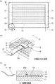
図1(a)は、本発明の樹脂製リアウインドウの一例を模式的に示す平面図であり、図1(b)は、図1(a)に示すA部の拡大斜視図であり、図1(c)は、図1(b)のB−B線断面図である。 Fig.1 (a) is a top view which shows typically an example of the resin-made rear windows of this invention, FIG.1 (b) is an expansion perspective view of the A section shown to Fig.1 (a), FIG. 1 (c) is a cross-sectional view taken along line BB in FIG. 1 (b).
図1(a)、図1(b)及び図1(c)に示す樹脂製リアウインドウ10は、第1樹脂基体11と、第1樹脂基体11と対向するように配置された第2樹脂基体12と、第1樹脂基体11及び第2樹脂基体12の間に配置された熱線13、並びに、熱線13と接続された給電用パッド14と、給電用パッド14と接続するための端子15aを備えるフレキシブル基板15と、からなる。フレキシブル基板15の一端は、端子15aが給電用パッド14と接続されるように第1樹脂基体11及び第2樹脂基体12の間に挟持されており、フレキシブル基板15の他端は、第1樹脂基体11及び第2樹脂基体12から外部に露出している。
A resin
図1(a)、図1(b)及び図1(c)に示す樹脂製リアウインドウ10では、第1樹脂基体11及び第2樹脂基体12は、それぞれの間に設けられた中間膜16を介して圧着されている。熱線13及び給電用パッド14は、中間膜16と第2樹脂基体12との間に配置されている。
In the resin
本発明の樹脂製リアウインドウにおいて、フレキシブル基板は、適度な屈曲性を有するものであれば特に限定されず、例えば、フィルム基板、プラスチック基板、金属基板等が挙げられる。フレキシブル基板の材料としては、ポリイミド、ガラスエポキシ、ガラスポリイミド、アルミニウム、鉄、ポリエチレン等が挙げられる。中でも、フレキシブル基板は、ポリイミドからなることが好ましく、ポリイミドフィルム基板であることがより好ましい。 In the resin rear window of the present invention, the flexible substrate is not particularly limited as long as it has appropriate flexibility, and examples thereof include a film substrate, a plastic substrate, and a metal substrate. Examples of the material for the flexible substrate include polyimide, glass epoxy, glass polyimide, aluminum, iron, and polyethylene. Among these, the flexible substrate is preferably made of polyimide, and more preferably a polyimide film substrate.
本発明の樹脂製リアウインドウにおいて、フレキシブル基板の厚さは特に限定されないが、10〜300μmであることが好ましく、20〜200μmであることがより好ましい。フレキシブル基板の厚さが10μm未満であると曲がりやすく、さらに屈曲しやすい基板となるため、給電用パッドや配線との接続性が低下しやすくなる。一方、フレキシブル基板の厚さが300μmを超えると、屈曲性が低下しやすくなる。 In the resin rear window of the present invention, the thickness of the flexible substrate is not particularly limited, but is preferably 10 to 300 μm, and more preferably 20 to 200 μm. When the thickness of the flexible substrate is less than 10 μm, the substrate is easily bent and more easily bent, so that the connectivity with the power supply pad and the wiring tends to be lowered. On the other hand, if the thickness of the flexible substrate exceeds 300 μm, the flexibility tends to decrease.
本発明の樹脂製リアウインドウを構成するフレキシブル基板において、給電用パッドと接続するための端子の形状、大きさ及び個数は特に限定されず、給電用パッドの形状、大きさ及び個数に応じて適宜設定される。 In the flexible substrate constituting the resin rear window of the present invention, the shape, size, and number of terminals for connecting to the power supply pad are not particularly limited, and are appropriately determined according to the shape, size, and number of power supply pads. Is set.
本発明の樹脂製リアウインドウにおいて、フレキシブル基板の端子の表面には、Ni/Auめっき層が設けられていることが好ましい。フレキシブル基板の端子の表面にNi/Auめっき層を設けることによって、給電用パッドとの電気的接続を確実に行うことができる。 In the resin rear window of the present invention, a Ni / Au plating layer is preferably provided on the surface of the terminal of the flexible substrate. By providing the Ni / Au plating layer on the surface of the terminal of the flexible substrate, electrical connection with the power feeding pad can be reliably performed.
本発明の樹脂製リアウインドウにおいて、フレキシブル基板の端子の材料は特に限定されないが、銅、ニッケル等が好ましい。これらの材料は、電気伝導率が良好であり、導体として適している。 In the resin rear window of the present invention, the material of the terminal of the flexible substrate is not particularly limited, but copper, nickel and the like are preferable. These materials have good electrical conductivity and are suitable as conductors.
本発明の樹脂製リアウインドウにおいて、フレキシブル基板の端子の厚さは特に限定されないが、30〜500μmであることが好ましく、50〜300μmであることがより好ましい。端子の厚さが30μm未満であると、給電用パッドや配線との接続性が低下しやすくなり、端子の厚さが500μmを超えると、フレキシブル基板を曲げることによる圧縮応力が大きくなるため、フレキシブル基板が破壊されやすくなる。 In the resin rear window of the present invention, the thickness of the terminal of the flexible substrate is not particularly limited, but is preferably 30 to 500 μm, and more preferably 50 to 300 μm. If the thickness of the terminal is less than 30 μm, the connectivity with the power supply pad and the wiring tends to decrease, and if the thickness of the terminal exceeds 500 μm, the compressive stress due to bending of the flexible substrate increases, so that the The substrate is easily destroyed.
本発明の樹脂製リアウインドウにおいて、フレキシブル基板は、通常、端子と接続された導体層を備えている。導体層は、フレキシブル基板の片面に形成されていてもよいし、両面に形成されていてもよい。導体層の好ましい材料及び厚さは、端子と同様である。 In the resin rear window of the present invention, the flexible substrate usually includes a conductor layer connected to the terminal. The conductor layer may be formed on one side of the flexible substrate, or may be formed on both sides. A preferable material and thickness of the conductor layer are the same as those of the terminal.
本発明の樹脂製リアウインドウにおいて、フレキシブル基板の端子及び導体層は、例えば、基板材料である絶縁フィルムの表面にめっき処理を施すことによって、または、金属箔が貼り付けられた絶縁フィルムの金属箔にエッチング処理を施すことによって形成することができる。なお、端子は、導体層の一部として形成されることが好ましい。 In the resin rear window of the present invention, the terminal and the conductor layer of the flexible substrate are formed by, for example, plating the surface of the insulating film, which is a substrate material, or the metal foil of the insulating film to which the metal foil is attached. The film can be formed by performing an etching process. The terminal is preferably formed as a part of the conductor layer.
本発明の樹脂製リアウインドウにおいて、熱線の材料としては、例えば、銀、銅、タングステン、ニッケル、モリブデン、タンタル、ニッケル−クロム合金、鉄−クロム−アルミニウム合金等の導電性の金属又は合金が挙げられる。 In the resin rear window of the present invention, examples of the heat ray material include conductive metals or alloys such as silver, copper, tungsten, nickel, molybdenum, tantalum, nickel-chromium alloy, and iron-chromium-aluminum alloy. It is done.
本発明の樹脂製リアウインドウにおいて、熱線の形状は特に限定されるものではなく、種々の形状を取り得る。最も基本的な形状としては、互いに平行する複数の直線が所定の間隔で水平方向に形成されたパターンが挙げられる。熱線の形状は、互いに平行する複数の波形状の曲線が所定の間隔で繰り返されるパターン、又は、互いに平行する複数の直線の組み合わせが所定の間隔で繰り返されるパターンであってもよい。波形状の曲線としては、サインカーブ(正弦曲線)、上に凸の半円と下に凸の半円とが水平方向に繰り返された形状等が挙げられる。また、直線の組み合わせとしては、水平方向に対して45°の直線と−45°の直線とが繰り返された形状等が挙げられる。なお、直線の組み合わせの場合、屈曲している部分は、曲線から構成されていてもよい。 In the resin rear window of the present invention, the shape of the heat ray is not particularly limited, and can take various shapes. The most basic shape includes a pattern in which a plurality of straight lines parallel to each other are formed in a horizontal direction at a predetermined interval. The shape of the heat ray may be a pattern in which a plurality of parallel wave-shaped curves are repeated at a predetermined interval, or a combination of a plurality of straight lines parallel to each other is repeated at a predetermined interval. Examples of the wave-shaped curve include a sine curve (sine curve), a shape in which an upward convex semicircle and a downward convex semicircle are repeated in the horizontal direction. Further, examples of the combination of straight lines include a shape in which a 45 ° straight line and a −45 ° straight line are repeated with respect to the horizontal direction. In the case of a combination of straight lines, the bent portion may be configured by a curve.
本発明の樹脂製リアウインドウにおいて、熱線の厚さは、5〜50μmが好ましい。また、熱線の幅は、0.2〜0.8mmが好ましい。熱線の幅が0.2mm未満である場合には、熱線が細すぎるため、発熱の繰り返しにより断線が発生するおそれがある。一方、熱線の幅が0.8mmを超える場合には、単位長さ当たりの抵抗値を大きくすることが難しくなり、発熱させにくくなるばかりでなく、施工が目立ち、デザイン上の観点よりふさわしくない。 In the resin rear window of the present invention, the thickness of the heat ray is preferably 5 to 50 μm. The width of the heat ray is preferably 0.2 to 0.8 mm. If the width of the hot wire is less than 0.2 mm, the hot wire is too thin, and there is a risk of disconnection due to repeated heat generation. On the other hand, when the width of the hot wire exceeds 0.8 mm, it becomes difficult to increase the resistance value per unit length and it becomes difficult to generate heat, and the construction is conspicuous and is not suitable from the viewpoint of design.
本発明の樹脂製リアウインドウにおいて、給電用パッドの材料としては、例えば、銀、銅、タングステン、ニッケル、モリブデン、タンタル、ニッケル−クロム合金、鉄−クロム−アルミニウム合金等の導電性の金属又は合金が挙げられる。給電用パッドの材料は、熱線と同じ材料であることが好ましい。スクリーン印刷やインクジェット印刷等の方法を用いて熱線を形成する際、給電用パッドも同時に形成することができるためである。 In the resin rear window of the present invention, as a material for the power supply pad, for example, conductive metal or alloy such as silver, copper, tungsten, nickel, molybdenum, tantalum, nickel-chromium alloy, iron-chromium-aluminum alloy, etc. Is mentioned. The material of the power feeding pad is preferably the same material as the heat ray. This is because when a heat ray is formed using a method such as screen printing or ink jet printing, a power supply pad can be formed simultaneously.
本発明の樹脂製リアウインドウにおいて、給電用パッドの形状は特に限定されず、平面視で矩形、円形等の任意の形状を取り得る。また、給電用パッドの大きさ及び個数も特に限定されず、フレキシブル基板の端子の形状、大きさ及び個数に応じて適宜設定される。 In the resin rear window of the present invention, the shape of the power supply pad is not particularly limited, and may be any shape such as a rectangle or a circle in plan view. Further, the size and number of power supply pads are not particularly limited, and are appropriately set according to the shape, size, and number of terminals of the flexible substrate.
本発明の樹脂製リアウインドウにおいて、給電用パッドは、不可視部となる樹脂製リアウインドウの周縁部に配置されることが好ましい。給電用パッドが不可視部に配置されていると、運転時の視認性に優れる。 In the resin rear window of the present invention, it is preferable that the power supply pad is disposed on the peripheral edge portion of the resin rear window serving as an invisible portion. When the power feeding pad is disposed in the invisible portion, the visibility during driving is excellent.
本発明の樹脂製リアウインドウにおいて、給電用パッドの表面には、Ni/Auめっき層が設けられていることが好ましい。給電用パッドの表面にNi/Auめっき層を設けることによって、フレキシブル基板の端子との電気的接続を確実に行うことができる。 In the resin rear window of the present invention, a Ni / Au plating layer is preferably provided on the surface of the power supply pad. By providing the Ni / Au plating layer on the surface of the power supply pad, electrical connection with the terminal of the flexible substrate can be reliably performed.
本発明の樹脂製リアウインドウにおいて、熱線の両端には、複数の熱線と接続するバスバーが設けられていることが好ましい。バスバーの幅を熱線の幅より広くすることにより、発熱を防止することができる。なお、本発明の樹脂製リアウインドウにおいては、バスバーは熱線の一部であると考える。 In the resin rear window of the present invention, it is preferable that bus bars connected to a plurality of heat wires are provided at both ends of the heat wires. Heat generation can be prevented by making the width of the bus bar wider than the width of the heat wire. In the resin rear window of the present invention, the bus bar is considered to be a part of the heat ray.
本発明の樹脂製リアウインドウにおいて、熱線の両端にバスバーが設けられる場合、給電用パッドはバスバーの端部に設けられる。また、バスバーは、給電用パッドとともに、不可視部となる樹脂製リアウインドウの周縁部に配置されることが好ましい。 In the resin rear window of the present invention, when the bus bar is provided at both ends of the heat wire, the power supply pad is provided at the end of the bus bar. Moreover, it is preferable that a bus bar is arrange | positioned with the pad for electric power feeding at the peripheral part of the resin rear window used as an invisible part.
本発明の樹脂製リアウインドウにおいて、熱線の両端にバスバーが設けられる場合、バスバーの材料は特に限定されないが、熱線と同じ材料であることが好ましい。スクリーン印刷やインクジェット印刷等の方法を用いて熱線及び給電用パッドを形成する際、バスバーも同時に形成することができるためである。 In the resin rear window of the present invention, when the bus bar is provided at both ends of the heat wire, the material of the bus bar is not particularly limited, but is preferably the same material as the heat wire. This is because the bus bar can be formed at the same time when the heat ray and the power supply pad are formed using a method such as screen printing or inkjet printing.
本発明の樹脂製リアウインドウにおいて、熱線、給電用パッド及びバスバーは、例えば、銀ペースト等の導電性ペーストを中間膜又は樹脂基体の上にパターン状に印刷した後、焼成することにより形成することができる。 In the resin rear window of the present invention, the heat ray, the power supply pad, and the bus bar are formed by, for example, printing a conductive paste such as a silver paste on the intermediate film or the resin substrate in a pattern and then baking it. Can do.
本発明の樹脂製リアウインドウにおいて、第1樹脂基体及び第2樹脂基体は、いずれも透明な樹脂材料からなる基体である。樹脂材料としては、ポリカーボネート(PC)、ポリメチルメタクリレート(PMMA)、ポリ塩化ビニル(PVC)、ポリエチレンテレフタレート(PET)、ポリエチレンナフタレート(PEN)、ポリイミド(PI)、ポリスチレン(PS)等が挙げられる。これらの中では、樹脂基体は、ポリカーボネート又はポリメチルメタクリレートからなることが好ましい。これらの樹脂は、高い透光性を有している上に、複屈折がなく、充分な強度を有しているため、樹脂基体として好適に使用することができる。 In the resin rear window of the present invention, each of the first resin base and the second resin base is a base made of a transparent resin material. Examples of the resin material include polycarbonate (PC), polymethyl methacrylate (PMMA), polyvinyl chloride (PVC), polyethylene terephthalate (PET), polyethylene naphthalate (PEN), polyimide (PI), polystyrene (PS), and the like. . Among these, the resin substrate is preferably made of polycarbonate or polymethyl methacrylate. Since these resins have high translucency, do not have birefringence, and have sufficient strength, they can be suitably used as a resin substrate.
本発明の樹脂製リアウインドウにおいて、第1樹脂基体及び第2樹脂基体の形状は、特に限定されるものではなく、リアウインドウの形状に応じて適宜設定される。通常、リアウインドウは左右及び/又は上下に湾曲しているため、第1樹脂基体及び第2樹脂基体は、曲面状に湾曲していることが好ましい。 In the resin rear window of the present invention, the shapes of the first resin base and the second resin base are not particularly limited, and are appropriately set according to the shape of the rear window. Usually, since the rear window is curved left and right and / or up and down, the first resin base and the second resin base are preferably curved in a curved shape.
本発明の樹脂製リアウインドウにおいて、第1樹脂基体及び第2樹脂基体は、無色である必要はなく、有色であってもよい。 In the resin rear window of the present invention, the first resin base and the second resin base need not be colorless, and may be colored.
本発明の樹脂製リアウインドウにおいて、第1樹脂基体及び第2樹脂基体の表面粗さRzJISは、10nm以上であることが好ましく、50nm以下であることが好ましい。
樹脂基体の表面粗さRzJISが10nm未満であると、樹脂基体の表面積が小さくなるため、樹脂基体と中間膜との密着性や、後述するハードコート層等との密着性が充分に得られにくくなる。一方、樹脂基体の表面粗さRzJISが50nmを超えると、樹脂基体の透明性が低下しやすくなる。
なお、第1樹脂基体及び第2樹脂基体の表面粗さRzJISは、レーザー顕微鏡(キーエンス社製VK−X200violet仕様)を用いて表面の輪郭曲線を測定した後、JIS B 0601:2001に準拠して、走査距離を30μmとして測定することができる。
In the resin rear window of the present invention, the surface roughness Rz JIS of the first resin base and the second resin base is preferably 10 nm or more, and preferably 50 nm or less.
When the surface roughness Rz JIS of the resin substrate is less than 10 nm, the surface area of the resin substrate is reduced, so that the adhesion between the resin substrate and the intermediate film and the adhesion with the hard coat layer described later are sufficiently obtained. It becomes difficult. On the other hand, when the surface roughness Rz JIS of the resin substrate exceeds 50 nm, the transparency of the resin substrate tends to be lowered.
The surface roughness Rz JIS of the first resin substrate and the second resin substrate is based on JIS B 0601: 2001 after measuring the surface contour curve using a laser microscope (VK-X200 violet specification manufactured by Keyence Corporation). Thus, the scanning distance can be measured as 30 μm.
本発明の樹脂製リアウインドウにおいて、第1樹脂基体の厚さは、1〜5mmであることが好ましい。また、第2樹脂基体の厚さは、1〜5mmであることが好ましい。第2樹脂基体の厚さは、第1樹脂基体の厚さと同じであってもよいし、異なっていてもよい。
第1樹脂基体及び第2樹脂基体の厚さが上記範囲であると、リアウインドウとして必要な機械的強度を確保することができ、さらに、リアウインドウ全体に歪み等が発生しにくくなる。
In the resin rear window of the present invention, the thickness of the first resin substrate is preferably 1 to 5 mm. The thickness of the second resin substrate is preferably 1 to 5 mm. The thickness of the second resin substrate may be the same as or different from the thickness of the first resin substrate.
When the thicknesses of the first resin base and the second resin base are in the above ranges, the mechanical strength necessary for the rear window can be ensured, and further, distortion and the like are hardly generated in the entire rear window.
本発明の樹脂製リアウインドウにおいて、第1樹脂基体及び第2樹脂基体の厚さは、いずれも一定であることが好ましい。 In the resin rear window of the present invention, it is preferable that the thicknesses of the first resin base and the second resin base are both constant.
本発明の樹脂製リアウインドウにおいて、第1樹脂基体の主面の面積は、第2樹脂基体の主面の面積よりも大きく、樹脂製リアウインドウの周縁部に樹脂製リアウインドウの中央部よりも薄い領域が存在することが好ましい。この場合、第1樹脂基体及び第2樹脂基体の厚さは、いずれも一定であることが好ましい。第1樹脂基体の主面の面積を第2樹脂基体の主面の面積よりも大きくすることにより、樹脂製リアウインドウの周縁部に、周縁部以外の中央部よりも薄い領域を設けることができる。 In the resin rear window of the present invention, the area of the main surface of the first resin base is larger than the area of the main surface of the second resin base, and the peripheral part of the resin rear window is larger than the central part of the resin rear window. Preferably there is a thin area. In this case, it is preferable that the thicknesses of the first resin base and the second resin base are both constant. By making the area of the main surface of the first resin base larger than the area of the main surface of the second resin base, it is possible to provide an area thinner than the central part other than the peripheral part in the peripheral part of the resin rear window. .
本発明の樹脂製リアウインドウにおいて、周縁部に中央部よりも薄い領域が存在する場合、当該薄い領域は不可視部に存在することが好ましい。また、相対的に主面の面積が大きい第1樹脂基体が車外側、相対的に主面の面積が小さい第2樹脂基体が車内側に配置されることが好ましい。
運転時の視認性に影響しない周縁部を中央部よりも薄くすることによって、リアウインドウを軽量化することができる。また、周縁部以外の中央部の厚さが一定であると、ムラのない防曇効果を得ることができ、運転時の視認性にも優れている。さらに、中央部から周縁部に向かって連続的に薄くなる場合と異なり、中央部の厚さが一定であると、リアウインドウ全体がレンズ状となることを防ぐことができるため、太陽熱が車内に入り込んで温度ムラが生じるという問題も発生しにくい。
In the resin rear window of the present invention, when a region thinner than the central portion is present in the peripheral portion, the thin region is preferably present in the invisible portion. Moreover, it is preferable that the 1st resin base | substrate with a relatively large area of a main surface is arrange | positioned at the vehicle inside, and the 2nd resin base | substrate with a relatively small area of a main surface is arrange | positioned at the vehicle inside.
The rear window can be reduced in weight by making the peripheral part that does not affect the visibility during driving thinner than the central part. Further, when the thickness of the central portion other than the peripheral portion is constant, a uniform anti-fogging effect can be obtained and the visibility during driving is excellent. Furthermore, unlike the case where the thickness is continuously reduced from the central portion toward the peripheral portion, if the thickness of the central portion is constant, the entire rear window can be prevented from becoming a lens shape. The problem of temperature unevenness due to penetration is less likely to occur.
本発明の樹脂製リアウインドウにおいて、周縁部に中央部よりも薄い領域が存在する場合、周縁部の全体に中央部よりも薄い領域が存在してもよいし、周縁部の一部に中央部よりも薄い領域が存在してもよい。周縁部の一部に中央部よりも薄い領域が存在する場合、中央部と同じ厚さの周縁部は、リアウインドウの変形等を防止するための補強材(リブ)として機能する。 In the resin rear window of the present invention, when a region thinner than the central portion is present in the peripheral portion, a region thinner than the central portion may exist over the entire peripheral portion, or the central portion may be part of the peripheral portion. There may be thinner regions. When a region thinner than the central portion is present in a part of the peripheral portion, the peripheral portion having the same thickness as the central portion functions as a reinforcing material (rib) for preventing deformation or the like of the rear window.
図2は、本発明の樹脂製リアウインドウの別の一例を模式的に示す平面図である。
図2に示す樹脂製リアウインドウ20では、第1樹脂基体21の主面の面積が第2樹脂基体22の主面の面積よりも大きく、樹脂製リアウインドウ20の周縁部の全体に中央部よりも薄い領域が存在する。
FIG. 2 is a plan view schematically showing another example of the resin rear window of the present invention.
In the resin
図3は、本発明の樹脂製リアウインドウのさらに別の一例を模式的に示す平面図である。
図3に示す樹脂製リアウインドウ30では、第1樹脂基体31の主面の面積が第2樹脂基体32の主面の面積よりも大きく、樹脂製リアウインドウ30の周縁部の一部に中央部よりも薄い領域が存在する。
FIG. 3 is a plan view schematically showing still another example of the resin rear window of the present invention.
In the resin
本発明の樹脂製リアウインドウにおいては、第1樹脂基体及び第2樹脂基体の主面のうち、熱線と反対側の主面の少なくとも一方の上にプライマー層が設けられ、プライマー層の上にハードコート層が設けられていることが好ましい。プライマー層及びハードコート層は、車外側に配置されることになる樹脂基体の主面の上に少なくとも設けられることが好ましく、第1樹脂基体及び第2樹脂基体の熱線と反対側の両主面の上に設けられることがより好ましい。 In the resin rear window of the present invention, a primer layer is provided on at least one of the main surfaces of the first resin substrate and the second resin substrate opposite to the heat ray, and the hard layer is formed on the primer layer. A coat layer is preferably provided. The primer layer and the hard coat layer are preferably provided at least on the main surface of the resin substrate to be disposed outside the vehicle, and both main surfaces of the first resin substrate and the second resin substrate on the opposite side to the heat rays. It is more preferable to be provided on the top.
本発明の樹脂製リアウインドウにおいて、ハードコート層の上には、セラミック層がさらに設けられていてもよい。この場合、セラミック層は、車外側に配置されることになるハードコート層の上に少なくとも設けられることが好ましい。ハードコート層の上にセラミック層を形成することにより、表面硬度をさらに高くすることができ、かつ、耐久性を向上させることもできる。 In the resin rear window of the present invention, a ceramic layer may be further provided on the hard coat layer. In this case, it is preferable that the ceramic layer is provided at least on the hard coat layer to be disposed outside the vehicle. By forming the ceramic layer on the hard coat layer, the surface hardness can be further increased and the durability can be improved.
図4は、プライマー層及びハードコート層が設けられた場合の本発明の樹脂製リアウインドウの一例を模式的に示す拡大断面図である。
図4では、図1(c)と同様、熱線13及び中間膜16は、いずれも第1樹脂基体11及び第2樹脂基体12の間に配置されている。第1樹脂基体11の熱線13と反対側の主面の上にはプライマー層17aが設けられ、プライマー層17aの上にはハードコート層18aが設けられている。また、第2樹脂基体12の熱線13と反対側の主面の上にはプライマー層17bが設けられ、プライマー層17bの上にはハードコート層18bが設けられている。さらに、第1樹脂基体11側のハードコート層18aの上にはセラミック層19aが設けられている。なお、第2樹脂基体12側のハードコート層18bの上にセラミック層が設けられていてもよい。
FIG. 4 is an enlarged cross-sectional view schematically showing an example of the resin rear window of the present invention when a primer layer and a hard coat layer are provided.
In FIG. 4, as in FIG. 1C, the
本発明の樹脂製リアウインドウにおいて、プライマー層は、樹脂基体とハードコート層とを接着させるために設けられる層であり、樹脂材料からなる。
プライマー層を構成する樹脂材料は、樹脂基体及びハードコート層に対する接着性が良好であることが好ましく、例えば、アクリル樹脂、ウレタン樹脂、エポキシ樹脂、ポリエステル樹脂、ポリビニルアルコール樹脂、メラミン樹脂、シリコーン樹脂等が挙げられる。これらは、1種又は2種以上使用することができる。これらの材料は樹脂基体及びハードコート層との接着性に優れるため、プライマー層を介して樹脂基体及びハードコート層を強固に接着することができる。中でも、プライマー層を形成する材料は、アクリル樹脂、ウレタン樹脂又はエポキシ樹脂が好ましく、アクリル樹脂がより好ましい。なお、アクリル樹脂は、アクリル酸エステル又はメタクリル酸エステルの重合体である。
In the resin rear window of the present invention, the primer layer is a layer provided for bonding the resin substrate and the hard coat layer, and is made of a resin material.
The resin material constituting the primer layer preferably has good adhesion to the resin substrate and the hard coat layer, for example, acrylic resin, urethane resin, epoxy resin, polyester resin, polyvinyl alcohol resin, melamine resin, silicone resin, etc. Is mentioned. These can be used alone or in combination of two or more. Since these materials are excellent in adhesiveness to the resin substrate and the hard coat layer, the resin substrate and the hard coat layer can be firmly bonded via the primer layer. Especially, the material which forms a primer layer has an acrylic resin, a urethane resin, or an epoxy resin, and an acrylic resin is more preferable. The acrylic resin is a polymer of acrylic ester or methacrylic ester.
本発明の樹脂製リアウインドウにおいて、プライマー層がアクリル樹脂からなる場合、上記アクリル樹脂は、少なくとも、エチレン性不飽和結合を1分子中に少なくとも2個以上有するアクリレート系化合物を含有するものが好ましく、中でも(メタ)アクリロイル基を1分子中に2個以上有する多官能(メタ)アクリレートであることが好ましい。また、上記アクリル系樹脂は、上記多官能(メタ)アクリレートと組み合わせて、(メタ)アクリロイル基を1分子中に1個有する単官能(メタ)アクリレートを用いてもよい。単官能(メタ)アクリレートを併用することにより、ハードコート層の製膜性及び密着性が向上する。 In the resin rear window of the present invention, when the primer layer is made of an acrylic resin, the acrylic resin preferably contains at least an acrylate compound having at least two ethylenically unsaturated bonds in one molecule. Of these, polyfunctional (meth) acrylates having two or more (meth) acryloyl groups in one molecule are preferable. Moreover, the said acrylic resin may use the monofunctional (meth) acrylate which has one (meth) acryloyl group in 1 molecule in combination with the said polyfunctional (meth) acrylate. By using a monofunctional (meth) acrylate in combination, the film forming property and adhesion of the hard coat layer are improved.
本発明の樹脂製リアウインドウにおいて、プライマー層の厚さは特に限定されないが、樹脂基体及びハードコート層との接着性の観点から、1〜10μmが好ましく、3〜8μmがより好ましい。 In the resin rear window of the present invention, the thickness of the primer layer is not particularly limited, but 1 to 10 μm is preferable and 3 to 8 μm is more preferable from the viewpoint of adhesiveness to the resin substrate and the hard coat layer.
本発明の樹脂製リアウインドウにおいて、ハードコート層は、表面に傷等が発生することを防止するために設けられる層であり、樹脂材料からなる。
ハードコート層を構成する樹脂材料としては、例えば、シリコーン樹脂、シリカハイブリッドコンポジット、アクリル樹脂、メラミン樹脂等が挙げられる。これらは1種又は2種以上使用することができる。これらの材料を用いてハードコート層を形成することにより、表面硬度を高くすることができるため、表面に傷等が発生しにくいリアウインドウとすることができる。中でも、ハードコート層を形成する材料は、シリコーン樹脂が好ましい。
In the resin rear window of the present invention, the hard coat layer is a layer provided to prevent the surface from being scratched, and is made of a resin material.
Examples of the resin material constituting the hard coat layer include silicone resin, silica hybrid composite, acrylic resin, melamine resin, and the like. These can be used alone or in combination of two or more. By forming a hard coat layer using these materials, the surface hardness can be increased, so that a rear window in which scratches or the like hardly occur on the surface can be obtained. Among them, the material for forming the hard coat layer is preferably a silicone resin.
本発明の樹脂製リアウインドウにおいて、ハードコート層の厚さは特に限定されないが、高い表面硬度を得る観点から、1〜10μmが好ましく、2〜5μmがより好ましい。 In the resin rear window of the present invention, the thickness of the hard coat layer is not particularly limited, but is preferably 1 to 10 μm and more preferably 2 to 5 μm from the viewpoint of obtaining high surface hardness.
本発明の樹脂製リアウインドウにおいて、セラミック層は、酸化物セラミック、炭化物セラミック又は窒化物セラミック等の無機材料からなる。
セラミック層を構成する無機材料としては、透明な材料であることが好ましく、例えば、SiOxCy(0.5≦x≦1.7、0.2≦y≦2.0)、シリカ(SiO2)、アルミナ(Al2O3)、スズドープ酸化インジウム(ITO)、酸化インジウム(In2O3)、酸化スズ(SnO2)、酸化亜鉛(ZnO)、酸化チタン(TiO2)等が挙げられる。
In the resin rear window of the present invention, the ceramic layer is made of an inorganic material such as an oxide ceramic, a carbide ceramic, or a nitride ceramic.
The inorganic material constituting the ceramic layer is preferably a transparent material, for example, SiOxCy (0.5 ≦ x ≦ 1.7, 0.2 ≦ y ≦ 2.0), silica (SiO 2 ), Examples include alumina (Al 2 O 3 ), tin-doped indium oxide (ITO), indium oxide (In 2 O 3 ), tin oxide (SnO 2 ), zinc oxide (ZnO), and titanium oxide (TiO 2 ).
中でも、セラミック層は、SiOxCy(0.5≦x≦1.7、0.2≦y≦2.0)又はSiO2からなることが好ましい。
SiOxCyからなるセラミック層は、SiO2及びSiCをターゲットとした物理蒸着(PVD)法、SiCをターゲットとした酸素雰囲気下でのPVD法、プラズマCVD法等により形成することができる。また、SiO2からなるセラミック層は、SiO2をターゲットとしたPVD法、プラズマCVD法等により形成することができる。
Among them, the ceramic layer, SiOxCy (0.5 ≦ x ≦ 1.7,0.2 ≦ y ≦ 2.0) or preferably consists of SiO 2.
The ceramic layer made of SiOxCy can be formed by a physical vapor deposition (PVD) method using SiO 2 and SiC as targets, a PVD method in an oxygen atmosphere using SiC as a target, a plasma CVD method, or the like. Further, the ceramic layer of SiO 2 may be formed of SiO 2 target and the PVD method, a plasma CVD method or the like.
本発明の樹脂製リアウインドウにおいて、第1樹脂基体及び第2樹脂基体がポリカーボネートからなる場合、セラミック層はSiO2からなることが好ましく、第1樹脂基体及び第2樹脂基体がポリメチルメタクリレートからなる場合、セラミック層はSiOxCyからなることが好ましい。 In the resin rear window of the present invention, when the first resin base and the second resin base are made of polycarbonate, the ceramic layer is preferably made of SiO 2 , and the first resin base and the second resin base are made of polymethyl methacrylate. In this case, the ceramic layer is preferably made of SiOxCy.
本発明の樹脂製リアウインドウにおいて、セラミック層は、非晶質であることが好ましい。セラミック層が非晶質であると、セラミック層を透明にすることができる。 In the resin rear window of the present invention, the ceramic layer is preferably amorphous. When the ceramic layer is amorphous, the ceramic layer can be made transparent.
本発明の樹脂製リアウインドウにおいて、セラミック層の厚さは特に限定されないが、高い表面硬度を得る観点から、5〜300μmが好ましく、10〜100μmが好ましい。 In the resin rear window of the present invention, the thickness of the ceramic layer is not particularly limited, but is preferably 5 to 300 μm, more preferably 10 to 100 μm, from the viewpoint of obtaining high surface hardness.
セラミック層の厚さは、例えば、レーザー顕微鏡を用いて測定することができる。プライマー層及びハードコート層の厚さについても同様に測定することができる。
例えば、セラミック層の厚さは、樹脂基体の表面にプライマー層、ハードコート層及びセラミック層が形成された部分と、樹脂基体の表面にプライマー層及びハードコート層が形成され、セラミック層が形成されていない部分がある試料を準備し、樹脂基体の表面にプライマー層、ハードコート層及びセラミック層が形成された部分と形成されていない部分との境界の段差をまたぐようにレーザー顕微鏡を走査して、その段差の高さをセラミック層の厚さとして測定することができる。
The thickness of the ceramic layer can be measured using, for example, a laser microscope. The thickness of the primer layer and the hard coat layer can be measured in the same manner.
For example, the thickness of the ceramic layer is such that the primer layer, the hard coat layer and the ceramic layer are formed on the surface of the resin substrate, and the primer layer and the hard coat layer are formed on the surface of the resin substrate. Prepare a sample with a non-exposed part, and scan with a laser microscope so as to straddle the step difference between the part where the primer layer, hard coat layer and ceramic layer are formed on the surface of the resin substrate, and the part where it is not formed. The height of the step can be measured as the thickness of the ceramic layer.
本発明の樹脂製リアウインドウにおいて、プライマー層、ハードコート層及びセラミック層は、それぞれ単層構造を有している必要はなく、2層以上の複層構造を有していてもよい。 In the resin rear window of the present invention, each of the primer layer, the hard coat layer, and the ceramic layer does not need to have a single layer structure, and may have a multilayer structure of two or more layers.
本発明の樹脂製リアウインドウにおいては、フレキシブル基板の一端が第1樹脂基体及び第2樹脂基体の間に挟持されることによって、フレキシブル基板の端子が給電用パッドと接続されている限り、給電用パッドやフレキシブル基板の端子等の一部が第1樹脂基体及び第2樹脂基体から外部に露出していてもよい。 In the resin rear window of the present invention, as long as one end of the flexible substrate is sandwiched between the first resin base and the second resin base, the terminal of the flexible substrate is connected to the power supply pad. Part of the pads, terminals of the flexible substrate, and the like may be exposed to the outside from the first resin base and the second resin base.
本発明の樹脂製リアウインドウにおいて、熱線は、防曇用だけでなく、例えば融雪用等の用途に用いることも可能である。また、熱線は、アンテナ線として用いられてもよい。 In the resin rear window of the present invention, the heat ray can be used not only for anti-fogging but also for applications such as snow melting. Moreover, a heat ray may be used as an antenna wire.
[樹脂製リアウインドウの製造方法]
本発明の樹脂製リアウインドウは、熱線、給電用パッド及びフレキシブル基板を第1樹脂基体及び第2樹脂基体の間に挟み込み、加熱圧着することによって製造することができる。この際、フレキシブル基板の端子が給電用パッドと接続されるように、フレキシブル基板の一端を第1樹脂基体及び第2樹脂基体の間に挟み込む。
[Method of manufacturing resin rear window]
The resin rear window of the present invention can be manufactured by sandwiching a heat ray, a power feeding pad, and a flexible substrate between the first resin base and the second resin base and thermocompression bonding. At this time, one end of the flexible substrate is sandwiched between the first resin substrate and the second resin substrate so that the terminals of the flexible substrate are connected to the power supply pads.
なお、曲面状に湾曲した樹脂リアウインドウを製造する場合には、所定の形状に湾曲させた第1樹脂基体及び第2樹脂基体の間に熱線、給電用パッド及びフレキシブル基板を挟み込み、加熱圧着することが好ましい。 When manufacturing a resin rear window curved in a curved shape, a heat ray, a power supply pad, and a flexible substrate are sandwiched between the first resin base and the second resin base curved in a predetermined shape, and thermocompression bonded. It is preferable.
以下、本発明の樹脂製リアウインドウの製造方法の一例として、熱線及び給電用パッドが形成された中間膜とフレキシブル基板とを第1樹脂基体及び第2樹脂基体の間に挟み込み、加熱圧着する場合について説明する。 Hereinafter, as an example of a method for manufacturing a resin rear window of the present invention, an intermediate film on which a heat ray and a power supply pad are formed and a flexible substrate are sandwiched between a first resin substrate and a second resin substrate, followed by thermocompression bonding. Will be described.
(第1樹脂基体及び第2樹脂基体の準備)
第1樹脂基体及び第2樹脂基体としては[樹脂製リアウインドウ]で説明した樹脂基体を使用することができ、所定の形状を有する2枚の樹脂基体を準備する。
(Preparation of first resin substrate and second resin substrate)
As the first resin substrate and the second resin substrate, the resin substrate described in [Resin Rear Window] can be used, and two resin substrates having a predetermined shape are prepared.
また、樹脂基体の表面の不純物を除去するために、洗浄処理を行うことが好ましい。
上記洗浄処理としては特に限定されず、従来公知の洗浄処理を用いることができ、例えば、水やアルコール溶媒中で超音波洗浄を行う方法等を用いることができる。また、スパッタリング装置内に樹脂基体を設置し、プラズマを発生させることによって樹脂基体の表面をプラズマ洗浄してもよい。
Further, it is preferable to perform a cleaning treatment in order to remove impurities on the surface of the resin substrate.
The cleaning process is not particularly limited, and a conventionally known cleaning process can be used. For example, a method of performing ultrasonic cleaning in water or an alcohol solvent can be used. Further, the surface of the resin substrate may be plasma-cleaned by installing a resin substrate in the sputtering apparatus and generating plasma.
上記洗浄処理後には、必要に応じて、樹脂基体の表面の粗さを調整したりするために、樹脂基体の表面に粗化処理を施してもよい。例えば、サンドブラスト処理、エッチング処理等の粗化処理を施してもよい。これらは単独で用いてもよいし、2種以上併用してもよい。
粗化処理後に、さらに洗浄処理を行ってもよい。
樹脂基体表面の好ましい表面粗さ等については[樹脂製リアウインドウ]で既に説明したので、ここではその説明を省略する。
After the washing treatment, the surface of the resin substrate may be roughened to adjust the surface roughness of the resin substrate as necessary. For example, you may perform roughening processes, such as a sandblast process and an etching process. These may be used alone or in combination of two or more.
You may perform a washing process after a roughening process.
Since the preferable surface roughness of the resin substrate surface has already been described in [Resin rear window], the description thereof is omitted here.
(熱線及び給電用パッドの形成)
熱線及び給電用パッドを中間膜上に形成する方法は特に限定されるものではないが、スクリーン印刷法、インクジェット印刷法、メッキ法、中間膜に貼り付けた金属箔をエッチングする方法、マスクを介したPVD法等が挙げられる。これらの中では、スクリーン印刷法、インクジェット印刷法又はメッキ法が好ましい。中間膜上には、熱線の両端にバスバーを形成してもよい。
中間膜、熱線及び給電用パッド等については[樹脂製リアウインドウ]で既に説明したので、ここではその説明を省略する。
(Formation of heat wires and power supply pads)
The method of forming the heat ray and the power supply pad on the intermediate film is not particularly limited. However, the screen printing method, the ink jet printing method, the plating method, the method of etching the metal foil attached to the intermediate film, and the mask are used. The PVD method etc. which were made. Among these, screen printing, ink jet printing, or plating is preferable. On the intermediate film, bus bars may be formed at both ends of the hot wire.
Since the intermediate film, the heat ray, the power supply pad, and the like have already been described in [Resin rear window], description thereof is omitted here.
(加熱圧着)
熱線及び給電用パッドが形成された中間膜及びフレキシブル基板を第1樹脂基体及び第2樹脂基体の間に挟み込み、加熱圧着する。この際、フレキシブル基板の端子が給電用パッドと接続されるように、フレキシブル基板の一端を第1樹脂基体及び第2樹脂基体の間に挟み込む。
フレキシブル基板については[樹脂製リアウインドウ]で既に説明したので、ここではその説明を省略する。
以上の工程によって、本発明の樹脂製リアウインドウを製造することができる。
(Heat bonding)
The intermediate film and the flexible substrate on which the heat wires and the power supply pads are formed are sandwiched between the first resin base and the second resin base, and thermocompression bonded. At this time, one end of the flexible substrate is sandwiched between the first resin substrate and the second resin substrate so that the terminals of the flexible substrate are connected to the power supply pads.
Since the flexible substrate has already been described in [Resin rear window], the description thereof is omitted here.
Through the above steps, the resin rear window of the present invention can be manufactured.
(プライマー層の形成)
樹脂基体の主面の上にプライマー層を形成する場合、例えば、[樹脂製リアウインドウ]で説明したプライマー層を構成する樹脂材料を含む溶液を樹脂基体の主面の上に塗布した後、乾燥、硬化させればよい。あるいは、プライマー層となるフィルムを樹脂基体の主面の上に貼り付けてもよい。
上記樹脂材料を含む溶液を塗布する方法としては、例えば、スプレーコート法、ディップコート法、フローコート法等が挙げられる。
(Formation of primer layer)
When the primer layer is formed on the main surface of the resin substrate, for example, a solution containing the resin material constituting the primer layer described in [Resin rear window] is applied on the main surface of the resin substrate and then dried. It can be cured. Or you may affix the film used as a primer layer on the main surface of a resin base | substrate.
Examples of the method for applying the solution containing the resin material include a spray coating method, a dip coating method, and a flow coating method.
(ハードコート層の形成)
プライマー層の上にハードコート層を形成する場合、例えば、[樹脂製リアウインドウ]で説明したハードコート層を構成する樹脂材料を含む溶液をプライマー層の上に塗布した後、乾燥、硬化させればよい。あるいは、ハードコート層となるフィルムをプライマー層の上に貼り付けてもよい。
上記樹脂材料を含む溶液を塗布する方法としては、例えば、スプレーコート法、ディップコート法、フローコート法等が挙げられる。
(Formation of hard coat layer)
In the case of forming a hard coat layer on the primer layer, for example, a solution containing the resin material constituting the hard coat layer described in [Resin rear window] is applied on the primer layer, and then dried and cured. That's fine. Or you may affix the film used as a hard-coat layer on a primer layer.
Examples of the method for applying the solution containing the resin material include a spray coating method, a dip coating method, and a flow coating method.
プライマー層及びハードコート層を硬化させる方法は特に限定されず、熱硬化、紫外線硬化、電子線硬化、常温硬化等の各方法を使用でき、材料に応じて適宜選択すればよい。また、プライマー層及びハードコート層は、プライマー層を硬化させた後、ハードコート層を形成してもよく、プライマー層及びハードコート層を同時に硬化させてもよい。 The method for curing the primer layer and the hard coat layer is not particularly limited, and each method such as thermal curing, ultraviolet curing, electron beam curing, and room temperature curing can be used, and may be appropriately selected depending on the material. Further, the primer layer and the hard coat layer may be formed after the primer layer is cured, or the primer layer and the hard coat layer may be cured simultaneously.
(セラミック層の形成)
ハードコート層の上にセラミック層を形成する場合、セラミック層は、PVD法又はプラズマCVD法により形成することができる。
PVD法又はプラズマCVD法によりセラミック層を形成する場合、樹脂材料からなる樹脂基体、プライマー層等の温度が高温にならず、樹脂材料の耐熱温度以下の温度でセラミック層を形成することができるので、樹脂材料へのセラミック層の形成方法として適している。
(Ceramic layer formation)
When a ceramic layer is formed on the hard coat layer, the ceramic layer can be formed by a PVD method or a plasma CVD method.
When the ceramic layer is formed by the PVD method or the plasma CVD method, the temperature of the resin substrate made of the resin material, the primer layer, etc. does not become high, and the ceramic layer can be formed at a temperature lower than the heat resistant temperature of the resin material. It is suitable as a method for forming a ceramic layer on a resin material.
PVD法の場合、5〜200℃でセラミック層を形成することが好ましい。この温度はチャンバー内の設定温度であり、常温(25℃±15℃)であることも好ましい。 In the case of the PVD method, it is preferable to form the ceramic layer at 5 to 200 ° C. This temperature is a set temperature in the chamber, and is preferably room temperature (25 ° C. ± 15 ° C.).
PVD法は、スパッタリング、真空蒸着、イオンプレーティング、又は、イオンビーム蒸着により行われることが好ましい。
これらの中でも、スパッタリングにより行われることがより好ましい。スパッタリングの方法としては、マグネトロンスパッタリング、イオンビームスパッタリング、2極スパッタリング、反応性スパッタリング、ECRスパッタリング等が挙げられる。
特に、RF(交流、高周波)スパッタリングが好ましく、RFマグネトロンスパッタリングがより好ましい。RFスパッタリングであると、絶縁体であるセラミックターゲットについてもスパッタリングが可能であり、マグネトロンスパッタリングとすることによって成膜速度を速くすることができる。
The PVD method is preferably performed by sputtering, vacuum deposition, ion plating, or ion beam deposition.
Among these, it is more preferable to carry out by sputtering. Examples of the sputtering method include magnetron sputtering, ion beam sputtering, bipolar sputtering, reactive sputtering, ECR sputtering, and the like.
In particular, RF (alternating current, high frequency) sputtering is preferable, and RF magnetron sputtering is more preferable. When RF sputtering is used, sputtering is also possible for a ceramic target that is an insulator, and the film formation rate can be increased by using magnetron sputtering.
RFマグネトロンスパッタリングを行う場合には、セラミック層の材料となるターゲットをスパッタリング装置に設置して、樹脂基体をチャンバー内に載置し、チャンバー内をAr雰囲気としてチャンバー内の圧力を例えば0.2〜1.2Paに減圧する。
そして、高周波電圧を印加してスパッタリングを所定時間行い、所定の厚さのセラミック層をハードコート層上に形成する。
When performing RF magnetron sputtering, a target to be a material of the ceramic layer is placed in a sputtering apparatus, a resin substrate is placed in the chamber, the inside of the chamber is an Ar atmosphere, and the pressure in the chamber is, for example, 0.2 to The pressure is reduced to 1.2 Pa.
Then, sputtering is performed for a predetermined time by applying a high frequency voltage, and a ceramic layer having a predetermined thickness is formed on the hard coat layer.
SiOxCy(0.5≦x≦1.7、0.2≦y≦2.0)からなるセラミック層をPVD法により形成する際には、SiO2及びSiCの両方をターゲットとし、両者に流す電力の大きさを調整することにより、SiOxCyの組成を制御することができる。
また、SiOxCy(0.5≦x≦1.7、0.2≦y≦2.0)からなるセラミック層をPVD法により形成する際には、SiCをターゲットとし、雰囲気中の酸素濃度及びターゲットに流す電力の大きさを調整することにより、SiOxCyの組成を制御することができる。
一方、SiOxCy(0.5≦x≦1.7、0.2≦y≦2.0)からなるセラミック層をプラズマCVD法により形成する際には、原料となる有機シリコーンの種類や電力の大きさ、原料ガスの流量や酸素ガス等の流量を調整することにより、SiOxCyの組成を制御することができる。
When a ceramic layer made of SiOxCy (0.5 ≦ x ≦ 1.7, 0.2 ≦ y ≦ 2.0) is formed by the PVD method, both SiO 2 and SiC are used as targets and electric power is supplied to both. The composition of SiOxCy can be controlled by adjusting the size of.
When a ceramic layer made of SiOxCy (0.5 ≦ x ≦ 1.7, 0.2 ≦ y ≦ 2.0) is formed by the PVD method, SiC is used as a target, the oxygen concentration in the atmosphere and the target The composition of SiOxCy can be controlled by adjusting the magnitude of the electric power supplied to the substrate.
On the other hand, when a ceramic layer made of SiOxCy (0.5 ≦ x ≦ 1.7, 0.2 ≦ y ≦ 2.0) is formed by the plasma CVD method, the kind of organic silicone used as a raw material and the magnitude of electric power are large. The composition of SiOxCy can be controlled by adjusting the flow rate of the source gas and the oxygen gas.
なお、[樹脂製リアウインドウ]で説明したように、熱線及び給電用パッドを第1樹脂基体及び第2樹脂基体の間に配置する方法としては、熱線及び給電用パッドを中間膜上に形成する方法以外にも、熱線及び給電用パッドを樹脂基体の内面に形成する方法、熱線及び給電用パッドが形成されたフィルムを中間膜と樹脂基体との間に介挿する方法等が挙げられる。熱線及び給電用パッドを樹脂基体上又はフィルム上に形成する方法は、中間膜上に形成する方法と同様である。 As described in [Resin Rear Window], as a method of arranging the heat ray and the power supply pad between the first resin base and the second resin base, the heat ray and the power supply pad are formed on the intermediate film. In addition to the method, a method of forming a heat ray and a power supply pad on the inner surface of the resin base, a method of inserting a film on which the heat ray and the power supply pad are formed between the intermediate film and the resin base, and the like can be mentioned. The method of forming the heat ray and the power feeding pad on the resin substrate or the film is the same as the method of forming the heat wire and the power supply pad on the intermediate film.
[樹脂製ウインドウ]
本発明の樹脂製ウインドウは、樹脂基体と、上記樹脂基体の表面又は内部に配置された導体、及び、上記導体と接続された給電用パッドと、上記給電用パッドと接続するための端子を備えるフレキシブル基板と、からなり、上記フレキシブル基板の一端は、上記端子が上記給電用パッドと接続されるように上記樹脂基体と固定されており、上記フレキシブル基板の他端は、上記樹脂基体から外部に露出していることを特徴とする。
[Resin window]
The resin window of the present invention includes a resin base, a conductor disposed on or inside the resin base, a power supply pad connected to the conductor, and a terminal for connecting to the power supply pad. A flexible substrate, and one end of the flexible substrate is fixed to the resin base so that the terminal is connected to the power supply pad, and the other end of the flexible substrate is external to the resin base. It is exposed.
本発明の樹脂製ウインドウでは、樹脂基体の枚数、導体の種類、導体及び給電用パッドが配置される位置、フレキシブル基板を樹脂基板と固定する方法、並びに、ウインドウの用途が限定されない点において、本発明の樹脂製リアウインドウと異なる。 In the resin window of the present invention, the number of resin bases, the type of conductor, the position where the conductor and the power supply pad are arranged, the method of fixing the flexible substrate to the resin substrate, and the use of the window are not limited. It differs from the resin rear window of the invention.
図5は、本発明の樹脂製ウインドウの一例を模式的に示す平面図である。
図5に示す樹脂製ウインドウ40は、樹脂基体41と、樹脂基体41の表面に配置された導体43、及び、導体43と接続された給電用パッド44と、給電用パッド44と接続するための端子(図示せず)を備えるフレキシブル基板45と、からなる。導体43及び給電用パッド44は、いずれも樹脂基体41の表面に配置されている。
FIG. 5 is a plan view schematically showing an example of the resin window of the present invention.
A
フレキシブル基板45の一端は、上記端子が給電用パッド44と接続されるように樹脂基体41と固定されており、フレキシブル基板45の他端は、樹脂基体41から外部に露出している。図5に示す樹脂製ウインドウ40では、さらに、接着テープ46によってフレキシブル基板45が樹脂基体41に固定されている。
One end of the
本発明の樹脂製ウインドウにおいて、樹脂基体の枚数は特に限定されず、1枚であってもよいし、2枚であってもよいし、3枚以上であってもよい。樹脂基体の合計厚さは、1〜10mmであることが好ましい。
樹脂基体の材料、形状等については、[樹脂製リアウインドウ]で説明した第1樹脂基体及び第2樹脂基体と同様であるので、ここではその説明を省略する。
In the resin window of the present invention, the number of resin bases is not particularly limited, and may be one, two, or three or more. The total thickness of the resin substrate is preferably 1 to 10 mm.
The material, shape, and the like of the resin base are the same as those of the first resin base and the second resin base described in [Resin rear window], and thus description thereof is omitted here.
本発明の樹脂製ウインドウにおいて、導体及び給電用パッドが配置される位置は特に限定されない。例えば、樹脂基体が1枚である場合、導体及び給電用パッドは、樹脂基体の表面に配置されていることが好ましい。また、樹脂基体が2枚以上である場合、導体及び給電用パッドは、樹脂基体の表面に配置されていてもよいし、樹脂基体の内部に配置されていてもよい。
本発明の樹脂製ウインドウにおいて、樹脂基体に配置される導体は熱線に限定されない。
熱線及び給電用パッドの材料、形状等については、[樹脂製リアウインドウ]で説明したので、ここではその説明を省略する。
本発明の樹脂製リアウインドウと同様、給電用パッドの表面には、Ni/Auめっき層が設けられていることが好ましい。また、熱線等の導体の両端には、複数の導体と接続するバスバーが設けられていることが好ましい。
In the resin window of the present invention, the position where the conductor and the power supply pad are arranged is not particularly limited. For example, when the number of the resin base is one, it is preferable that the conductor and the power supply pad are disposed on the surface of the resin base. When there are two or more resin substrates, the conductor and the power feeding pad may be disposed on the surface of the resin substrate, or may be disposed inside the resin substrate.
In the resin window of the present invention, the conductor disposed on the resin substrate is not limited to the heat ray.
The material, shape, and the like of the heat wire and the power supply pad have been described in [Resin rear window], and thus description thereof is omitted here.
Similar to the resin rear window of the present invention, a Ni / Au plating layer is preferably provided on the surface of the power feeding pad. Moreover, it is preferable that the bus bar connected with a some conductor is provided in the both ends of conductors, such as a heat ray.
本発明の樹脂製ウインドウにおいて、フレキシブル基板を樹脂基板と固定する方法は特に限定されず、フレキシブル基板を2枚の樹脂基体の間に挟持する方法以外にも、例えば、銀ペースト等の導電性ペーストを用いてフレキシブル基板の端子と給電用パッドとを固定するとともに、接着テープを用いてフレキシブル基板を樹脂基体に固定する方法等が挙げられる。
フレキシブル基板の材料や厚さ、端子の材料や厚さ等については、[樹脂製リアウインドウ]で説明したので、ここではその説明を省略する。
本発明の樹脂製リアウインドウと同様、フレキシブル基板の端子の表面には、Ni/Auめっき層が設けられていることが好ましい。
In the resin window of the present invention, the method of fixing the flexible substrate to the resin substrate is not particularly limited, and other than the method of sandwiching the flexible substrate between two resin substrates, for example, a conductive paste such as silver paste A method of fixing the flexible substrate to the resin substrate using an adhesive tape and the like, while fixing the terminal of the flexible substrate and the power feeding pad using the adhesive.
Since the material and thickness of the flexible substrate and the material and thickness of the terminal have been described in [Resin rear window], the description thereof is omitted here.
Similar to the resin rear window of the present invention, a Ni / Au plating layer is preferably provided on the surface of the terminal of the flexible substrate.
本発明の樹脂製ウインドウにおいては、樹脂基体の上にプライマー層が設けられ、プライマー層の上にハードコート層が設けられていることが好ましい。ハードコート層の上には、セラミック層がさらに設けられていてもよい。
なお、樹脂基体の表面に導体及び給電用パッドが配置されている場合には、導体及び給電用パッドを含む樹脂基体の上にプライマー層が設けられる。
プライマー層、ハードコート層及びセラミック層については、[樹脂製リアウインドウ]で説明したので、ここではその説明を省略する。
In the resin window of the present invention, it is preferable that a primer layer is provided on the resin substrate, and a hard coat layer is provided on the primer layer. A ceramic layer may be further provided on the hard coat layer.
When the conductor and the power feeding pad are arranged on the surface of the resin base, a primer layer is provided on the resin base including the conductor and the power feeding pad.
Since the primer layer, the hard coat layer, and the ceramic layer have been described in [Resin rear window], description thereof is omitted here.
本発明の樹脂製ウインドウは、自動車用のガラスとして使用されることが好ましく、具体的には、リアウインドウ、フロントウインドウ又はサイドウインドウに使用されることが好ましい。中でも、リアウインドウに使用されることが好ましい。 The resin window of the present invention is preferably used as glass for automobiles, and specifically, it is preferably used for a rear window, a front window, or a side window. Among these, it is preferable to be used for a rear window.
10,20,30 樹脂製リアウインドウ
11,21,31 第1樹脂基体
12,22,32 第2樹脂基体
13 熱線
14 給電用パッド
15 フレキシブル基板
15a 端子
16 中間膜
17a,17b プライマー層
18a,18b ハードコート層
19a セラミック層
40 樹脂製ウインドウ
41 樹脂基体
43 導体
44 給電用パッド
45 フレキシブル基板
46 接着テープ
10, 20, 30 Resin
Claims (7)
前記第1樹脂基体と対向するように配置された第2樹脂基体と、
前記第1樹脂基体及び前記第2樹脂基体の間に配置された熱線、並びに、前記熱線と接続された給電用パッドと、
前記給電用パッドと接続するための端子を備えるフレキシブル基板と、からなり、
前記フレキシブル基板の一端は、前記端子が前記給電用パッドと接続されるように前記第1樹脂基体及び前記第2樹脂基体の間に挟持されており、
前記フレキシブル基板の他端は、前記第1樹脂基体及び前記第2樹脂基体から外部に露出していることを特徴とする樹脂製リアウインドウ。 A first resin substrate;
A second resin base disposed to face the first resin base;
A heat wire disposed between the first resin substrate and the second resin substrate; and a power supply pad connected to the heat wire;
A flexible substrate comprising a terminal for connecting to the power supply pad,
One end of the flexible substrate is sandwiched between the first resin base and the second resin base so that the terminal is connected to the power supply pad,
The resin rear window is characterized in that the other end of the flexible substrate is exposed to the outside from the first resin base and the second resin base.
前記樹脂製リアウインドウの周縁部に前記樹脂製リアウインドウの中央部よりも薄い領域が存在する請求項1〜4のいずれかに記載の樹脂製リアウインドウ。 The area of the main surface of the first resin substrate is larger than the area of the main surface of the second resin substrate,
The resin rear window according to any one of claims 1 to 4, wherein an area thinner than a central portion of the resin rear window is present at a peripheral edge portion of the resin rear window.
前記樹脂基体の表面又は内部に配置された導体、及び、前記導体と接続された給電用パッドと、
前記給電用パッドと接続するための端子を備えるフレキシブル基板と、からなり、
前記フレキシブル基板の一端は、前記端子が前記給電用パッドと接続されるように前記樹脂基体と固定されており、
前記フレキシブル基板の他端は、前記樹脂基体から外部に露出していることを特徴とする樹脂製ウインドウ。 A resin substrate;
A conductor disposed on or inside the resin substrate, and a power supply pad connected to the conductor;
A flexible substrate comprising a terminal for connecting to the power supply pad,
One end of the flexible substrate is fixed to the resin base so that the terminal is connected to the power supply pad,
The other end of the flexible substrate is exposed to the outside from the resin substrate.
Priority Applications (1)
| Application Number | Priority Date | Filing Date | Title |
|---|---|---|---|
| JP2016036031A JP2017149380A (en) | 2016-02-26 | 2016-02-26 | Resin rear window and resin window |
Applications Claiming Priority (1)
| Application Number | Priority Date | Filing Date | Title |
|---|---|---|---|
| JP2016036031A JP2017149380A (en) | 2016-02-26 | 2016-02-26 | Resin rear window and resin window |
Publications (1)
| Publication Number | Publication Date |
|---|---|
| JP2017149380A true JP2017149380A (en) | 2017-08-31 |
Family
ID=59740376
Family Applications (1)
| Application Number | Title | Priority Date | Filing Date |
|---|---|---|---|
| JP2016036031A Pending JP2017149380A (en) | 2016-02-26 | 2016-02-26 | Resin rear window and resin window |
Country Status (1)
| Country | Link |
|---|---|
| JP (1) | JP2017149380A (en) |
Cited By (2)
| Publication number | Priority date | Publication date | Assignee | Title |
|---|---|---|---|---|
| JP2020095084A (en) * | 2018-12-10 | 2020-06-18 | 凸版印刷株式会社 | Light control film and light control device |
| JP2020100338A (en) * | 2018-12-25 | 2020-07-02 | 株式会社豊田自動織機 | Wiper structure for resin glass and wiper bar |
Citations (16)
| Publication number | Priority date | Publication date | Assignee | Title |
|---|---|---|---|---|
| US3288983A (en) * | 1963-07-29 | 1966-11-29 | Lear Jet Corp | Electrical resistance de-icing means for aircraft windshields |
| JPH0343063U (en) * | 1989-09-06 | 1991-04-23 | ||
| JPH0899610A (en) * | 1994-09-30 | 1996-04-16 | Tsutsunaka Plast Ind Co Ltd | Synthetic-resin-made window material having anti-fog performance and manufacture thereof |
| JP2005533739A (en) * | 2002-07-24 | 2005-11-10 | ピーピージー・インダストリーズ・オハイオ・インコーポレイテッド | Eliminates hot spots at the end of heatable transparency bus bars with conductive members |
| JP2006094398A (en) * | 2004-09-27 | 2006-04-06 | Matsushita Electric Works Ltd | Pressure wave generator |
| JP2006294410A (en) * | 2005-04-11 | 2006-10-26 | Kitagawa Ind Co Ltd | Connector and opening window member |
| JP2007295403A (en) * | 2006-04-26 | 2007-11-08 | Nippon Sheet Glass Co Ltd | Glass antenna system for vehicle and vehicle equipped with the same |
| JP2009283415A (en) * | 2008-05-26 | 2009-12-03 | Fuji Electric Retail Systems Co Ltd | Heating sheet and food ingredient storage device using this same |
| JP2010251230A (en) * | 2009-04-20 | 2010-11-04 | Fujifilm Corp | Electric window glass |
| JP2011101190A (en) * | 2009-11-05 | 2011-05-19 | Asahi Glass Co Ltd | Filter device for glass antenna and window glass for vehicle |
| JP2011240625A (en) * | 2010-05-19 | 2011-12-01 | Jx Nippon Mining & Metals Corp | Copper-clad laminated sheet |
| JP2013173402A (en) * | 2012-02-23 | 2013-09-05 | Asahi Glass Co Ltd | Fogging proof window for vehicle |
| JP2014514836A (en) * | 2011-04-06 | 2014-06-19 | サン−ゴバン グラス フランス | Flat conductor connection parts for antenna structures |
| JP2015001993A (en) * | 2013-06-14 | 2015-01-05 | 日本発條株式会社 | Suspension for disk unit |
| WO2015015553A1 (en) * | 2013-07-29 | 2015-02-05 | 大日本印刷株式会社 | Laminating film for use in organic glass |
| WO2015056582A1 (en) * | 2013-10-16 | 2015-04-23 | 旭硝子株式会社 | Electricity-supplying structure, resin plate for window provided with said structure, and method for manufacturing resin plate for window provided with electricity-supplying structure |
-
2016
- 2016-02-26 JP JP2016036031A patent/JP2017149380A/en active Pending
Patent Citations (16)
| Publication number | Priority date | Publication date | Assignee | Title |
|---|---|---|---|---|
| US3288983A (en) * | 1963-07-29 | 1966-11-29 | Lear Jet Corp | Electrical resistance de-icing means for aircraft windshields |
| JPH0343063U (en) * | 1989-09-06 | 1991-04-23 | ||
| JPH0899610A (en) * | 1994-09-30 | 1996-04-16 | Tsutsunaka Plast Ind Co Ltd | Synthetic-resin-made window material having anti-fog performance and manufacture thereof |
| JP2005533739A (en) * | 2002-07-24 | 2005-11-10 | ピーピージー・インダストリーズ・オハイオ・インコーポレイテッド | Eliminates hot spots at the end of heatable transparency bus bars with conductive members |
| JP2006094398A (en) * | 2004-09-27 | 2006-04-06 | Matsushita Electric Works Ltd | Pressure wave generator |
| JP2006294410A (en) * | 2005-04-11 | 2006-10-26 | Kitagawa Ind Co Ltd | Connector and opening window member |
| JP2007295403A (en) * | 2006-04-26 | 2007-11-08 | Nippon Sheet Glass Co Ltd | Glass antenna system for vehicle and vehicle equipped with the same |
| JP2009283415A (en) * | 2008-05-26 | 2009-12-03 | Fuji Electric Retail Systems Co Ltd | Heating sheet and food ingredient storage device using this same |
| JP2010251230A (en) * | 2009-04-20 | 2010-11-04 | Fujifilm Corp | Electric window glass |
| JP2011101190A (en) * | 2009-11-05 | 2011-05-19 | Asahi Glass Co Ltd | Filter device for glass antenna and window glass for vehicle |
| JP2011240625A (en) * | 2010-05-19 | 2011-12-01 | Jx Nippon Mining & Metals Corp | Copper-clad laminated sheet |
| JP2014514836A (en) * | 2011-04-06 | 2014-06-19 | サン−ゴバン グラス フランス | Flat conductor connection parts for antenna structures |
| JP2013173402A (en) * | 2012-02-23 | 2013-09-05 | Asahi Glass Co Ltd | Fogging proof window for vehicle |
| JP2015001993A (en) * | 2013-06-14 | 2015-01-05 | 日本発條株式会社 | Suspension for disk unit |
| WO2015015553A1 (en) * | 2013-07-29 | 2015-02-05 | 大日本印刷株式会社 | Laminating film for use in organic glass |
| WO2015056582A1 (en) * | 2013-10-16 | 2015-04-23 | 旭硝子株式会社 | Electricity-supplying structure, resin plate for window provided with said structure, and method for manufacturing resin plate for window provided with electricity-supplying structure |
Cited By (4)
| Publication number | Priority date | Publication date | Assignee | Title |
|---|---|---|---|---|
| JP2020095084A (en) * | 2018-12-10 | 2020-06-18 | 凸版印刷株式会社 | Light control film and light control device |
| JP7326733B2 (en) | 2018-12-10 | 2023-08-16 | 凸版印刷株式会社 | Light control film, light control device |
| JP2020100338A (en) * | 2018-12-25 | 2020-07-02 | 株式会社豊田自動織機 | Wiper structure for resin glass and wiper bar |
| WO2020137369A1 (en) * | 2018-12-25 | 2020-07-02 | 株式会社豊田自動織機 | Wiper structure for resin window and wiper rubber |
Similar Documents
| Publication | Publication Date | Title |
|---|---|---|
| JP6526863B2 (en) | Glass plate provided with electric heating layer and method of manufacturing the same | |
| US10770806B2 (en) | Electrical contact composites and method for producing electrical contact composites | |
| CN104919892B (en) | Pane having an electric heating layer | |
| JP6805279B2 (en) | Transparent plate material with heat coating and its manufacturing method and use | |
| CN106416422B (en) | Glass panels with electrically heated zones | |
| KR20150036256A (en) | Composite pane with electrical contact-making means | |
| JP6570541B2 (en) | Transparent plate with heat coating | |
| JP2010103041A (en) | Transparent film heater, glass with heater function, laminated glass with heater function, and automobile pane | |
| JP2018507152A (en) | Method for producing multilayer board with anticorrosive functional coating | |
| JP2017533535A (en) | Transparent window plate with electric heating layer, method for manufacturing transparent window plate and use of transparent window plate | |
| CN113905885A (en) | Coating deletion for electrical connections | |
| JP2022517948A (en) | Conductive busbars for electrical connections on vehicle windows | |
| CN106794532B (en) | Manufacture the method with the plate of conductive coating and the metal tape being welded thereon and corresponding plate | |
| JP2017149380A (en) | Resin rear window and resin window | |
| JPH0888077A (en) | Transparent sheet heater and manufacturing method thereof | |
| JP2017091888A (en) | Planar heating element and method of manufacturing planar heating element | |
| JP4006163B2 (en) | Touch panel | |
| CN115803188A (en) | Functional laminated glass article and method of making same | |
| JPH06283260A (en) | Transparent sheet heater and manufacturing method thereof | |
| JP2021075054A (en) | Anti-fog glass | |
| JP6764238B2 (en) | Rear window | |
| JP7581672B2 (en) | Conductive sheet, laminated plate, and moving body | |
| JP2017091686A (en) | Planar heating element and manufacturing method of the planar heating element |
Legal Events
| Date | Code | Title | Description |
|---|---|---|---|
| A621 | Written request for application examination |
Free format text: JAPANESE INTERMEDIATE CODE: A621 Effective date: 20190214 |
|
| A977 | Report on retrieval |
Free format text: JAPANESE INTERMEDIATE CODE: A971007 Effective date: 20191220 |
|
| A131 | Notification of reasons for refusal |
Free format text: JAPANESE INTERMEDIATE CODE: A131 Effective date: 20200107 |
|
| A521 | Request for written amendment filed |
Free format text: JAPANESE INTERMEDIATE CODE: A523 Effective date: 20200302 |
|
| A131 | Notification of reasons for refusal |
Free format text: JAPANESE INTERMEDIATE CODE: A131 Effective date: 20200804 |
|
| A02 | Decision of refusal |
Free format text: JAPANESE INTERMEDIATE CODE: A02 Effective date: 20210302 |