以下、本発明に係る実施の形態について、図面を参照して説明する。なお、各図中、同一又は相当する部分には同一の符号を付しており、その重複説明は適宜に簡略化ないし省略する。
Hereinafter, embodiments according to the present invention will be described with reference to the drawings. In addition, in each figure, the same code | symbol is attached | subjected to the part which is the same or it corresponds, The duplication description is simplified or abbreviate | omitted suitably.
図1は、本発明の一実施形態に係る画像形成装置の概略構成図である。
図1に示す画像形成装置は、画像形成部等を備える画像形成装置本体200と、その上方に配置された原稿読取装置100とで構成されている。画像形成部には、画像形成装置本体200に対して着脱可能な画像形成ユニットとしての4つのプロセスユニット1Y,1C,1M,1Bkが設けられている。各プロセスユニット1Y,1C,1M,1Bkは、カラー画像の色分解成分に対応するイエロー(Y)、シアン(C)、マゼンタ(M)、ブラック(Bk)の異なる色のトナーを収容している以外は同様の構成となっている。
FIG. 1 is a schematic configuration diagram of an image forming apparatus according to an embodiment of the present invention.
The image forming apparatus shown in FIG. 1 includes an image forming apparatus main body 200 having an image forming unit and the like, and a document reading apparatus 100 disposed above the image forming apparatus main body 200. The image forming unit is provided with four process units 1Y, 1C, 1M, and 1Bk as image forming units that can be attached to and detached from the image forming apparatus main body 200. Each process unit 1Y, 1C, 1M, 1Bk contains toner of different colors of yellow (Y), cyan (C), magenta (M), and black (Bk) corresponding to the color separation components of the color image. Other than that, the configuration is the same.
各プロセスユニット1Y,1C,1M,1Bkは、潜像担持体としてのドラム状の感光体2と、感光体2の表面を帯電させる帯電手段としての帯電ローラ3と、感光体2の表面にトナー像を形成する現像手段としての現像装置4と、感光体2の表面を清掃するクリーニング手段としてのクリーニングブレード5とを備えている。なお、図1では、イエローのプロセスユニット1Yが備える感光体2、帯電ローラ3、現像装置4、クリーニングブレード5のみに符号を付しており、その他のプロセスユニット1C,1M,1Bkにおいては符号を省略している。
Each of the process units 1Y, 1C, 1M, and 1Bk includes a drum-shaped photosensitive member 2 as a latent image carrier, a charging roller 3 as a charging unit that charges the surface of the photosensitive member 2, and a toner on the surface of the photosensitive member 2. A developing device 4 as a developing unit for forming an image and a cleaning blade 5 as a cleaning unit for cleaning the surface of the photoreceptor 2 are provided. In FIG. 1, only the photoconductor 2, the charging roller 3, the developing device 4, and the cleaning blade 5 included in the yellow process unit 1 </ b> Y are denoted by reference numerals, and the other process units 1 </ b> C, 1 </ b> M, and 1 </ b> Bk are denoted by reference numerals. Omitted.
図1において、各プロセスユニット1Y,1C,1M,1Bkの上方には、感光体2の表面を露光する露光手段としての露光装置6が配置されている。露光装置6は、光源、ポリゴンミラー、f−θレンズ、反射ミラー等を有し、画像データに基づいて各感光体2の表面へレーザ光を照射する。
In FIG. 1, an exposure device 6 as an exposure means for exposing the surface of the photoreceptor 2 is disposed above each process unit 1Y, 1C, 1M, 1Bk. The exposure device 6 includes a light source, a polygon mirror, an f-θ lens, a reflection mirror, and the like, and irradiates the surface of each photoreceptor 2 with laser light based on image data.
また、各プロセスユニット1Y,1C,1M,1Bkの下方には、転写装置7が配置されている。転写装置7は、転写体としての無端状のベルトから構成される中間転写ベルト10を有する。中間転写ベルト10は、支持部材としての複数のローラ21〜24に張架されている。これらのローラ21〜24のうちの1つが駆動ローラとして回転することによって、中間転写ベルト10は図の矢印に示す方向に周回走行(回転)する。
Further, a transfer device 7 is disposed below each of the process units 1Y, 1C, 1M, and 1Bk. The transfer device 7 has an intermediate transfer belt 10 constituted by an endless belt as a transfer body. The intermediate transfer belt 10 is stretched around a plurality of rollers 21 to 24 as support members. When one of these rollers 21 to 24 rotates as a driving roller, the intermediate transfer belt 10 runs (rotates) in the direction indicated by the arrow in the drawing.
4つの感光体2に対向する位置に、一次転写手段としての4つの一次転写ローラ11が配置されている。各一次転写ローラ11は中間転写ベルト10を介して感光体2に接触し、中間転写ベルト10と各感光体2との間に一次転写ニップが形成されている。
Four primary transfer rollers 11 as primary transfer means are arranged at positions facing the four photoconductors 2. Each primary transfer roller 11 is in contact with the photoreceptor 2 via the intermediate transfer belt 10, and a primary transfer nip is formed between the intermediate transfer belt 10 and each photoreceptor 2.
中間転写ベルト10を張架するローラの1つ(ローラ24)に対向する位置に、二次転写手段としての二次転写ローラ12が配置されている。二次転写ローラ12は中間転写ベルト10を介して対向するローラ24に接触し、二次転写ローラ12と中間転写ベルト10との間に二次転写ニップが形成されている。
A secondary transfer roller 12 as a secondary transfer unit is disposed at a position facing one of the rollers (roller 24) that stretches the intermediate transfer belt 10. The secondary transfer roller 12 comes into contact with the opposing roller 24 via the intermediate transfer belt 10, and a secondary transfer nip is formed between the secondary transfer roller 12 and the intermediate transfer belt 10.
画像形成装置本体200の下部には、紙やOHPフィルム等のシート状の記録材Pを収容する複数の給紙カセット13が配置されている。記録材Pとしてはロール状に巻かれた連続するものであってもよい。各給紙カセット13には、収容されている記録材Pを送り出す給紙ローラ14が設けてある。
A plurality of paper feed cassettes 13 that store sheet-like recording material P such as paper or an OHP film are disposed at the lower part of the image forming apparatus main body 200. The recording material P may be a continuous material wound in a roll shape. Each paper feed cassette 13 is provided with a paper feed roller 14 for feeding out the stored recording material P.
また、画像形成装置本体200には、記録材Pに画像を定着する定着装置8と、記録材Pを冷却する冷却装置9と、記録材Pを搬送する搬送手段としての一対のレジストローラ15と、記録材Pを機外に排出する一対の排出ローラ16と、機外に排出された記録材Pをストックする排紙トレイ20とが設けられている。定着装置8は、ヒータ等の加熱源によって加熱される定着部材としての定着ローラ17と、定着ローラ17に加圧される加圧部材としての加圧ローラ18とを備える。定着ローラ17と加圧ローラ18とが接触した箇所には、定着ニップが形成されている。なお、定着部材と加圧部材はローラの他、ベルトであっても構わない。
The image forming apparatus main body 200 includes a fixing device 8 that fixes an image on the recording material P, a cooling device 9 that cools the recording material P, and a pair of registration rollers 15 that serve as a conveying unit that conveys the recording material P. A pair of discharge rollers 16 for discharging the recording material P to the outside of the apparatus and a discharge tray 20 for stocking the recording material P discharged to the outside of the apparatus are provided. The fixing device 8 includes a fixing roller 17 as a fixing member that is heated by a heating source such as a heater, and a pressure roller 18 as a pressure member that is pressed against the fixing roller 17. A fixing nip is formed at a position where the fixing roller 17 and the pressure roller 18 are in contact with each other. The fixing member and the pressure member may be belts in addition to rollers.
画像形成装置本体200内には、搬送媒体でもある記録材Pを搬送するための搬送媒体搬送路25が形成されている。搬送媒体搬送路25は、記録材Pを給紙カセット13から機外にまで搬送するための主搬送路26と、記録材Pをスイッチバックさせて搬送するための反転路27と、反転路27から主搬送路26に記録材Pを再供給するための再供給路28とで構成されている。反転路27は、主搬送路26に対して冷却装置9と排出ローラ16との間で分岐している。再供給路28は、反転路27から分岐し、レジストローラ15の搬送方向上流側近傍で主搬送路26に合流している。主搬送路26に対する反転路27の分岐箇所と反転路27に対する再供給路28の分岐箇所には、それぞれ経路を切り換える経路切換部材としての切換爪29A,29Bが揺動可能に設けられている。また、主搬送路26、反転路27及び再供給路28には、それぞれ搬送ローラ19A〜19Gが設けられている。
In the image forming apparatus main body 200, a conveyance medium conveyance path 25 for conveying the recording material P that is also a conveyance medium is formed. The conveyance medium conveyance path 25 includes a main conveyance path 26 for conveying the recording material P from the paper feed cassette 13 to the outside of the apparatus, a reversing path 27 for conveying the recording material P by switching back, and a reversing path 27. And a re-feeding path 28 for re-feeding the recording material P to the main transport path 26. The reverse path 27 is branched between the cooling device 9 and the discharge roller 16 with respect to the main transport path 26. The resupply path 28 branches off from the reversing path 27 and joins the main transport path 26 in the vicinity of the upstream side of the registration roller 15 in the transport direction. Switching claws 29 </ b> A and 29 </ b> B as path switching members for switching paths are swingably provided at a branching point of the reversing path 27 with respect to the main conveyance path 26 and a branching point of the resupply path 28 with respect to the reversing path 27. Further, conveyance rollers 19 </ b> A to 19 </ b> G are provided in the main conveyance path 26, the reverse path 27, and the resupply path 28, respectively.
以下、図1を参照して上記画像形成装置の基本的動作について説明する。
作像動作が開始されると、各プロセスユニット1Y,1C,1M,1Bkの感光体2が図の反時計回りに回転駆動され、帯電ローラ3によって各感光体2の表面が所定の極性に一様に帯電される。原稿読取装置100によって読み取られた原稿の画像情報又は端末からプリント指示されたプリント情報に基づいて、露光装置6から帯電された各感光体2の表面にレーザ光が照射されて、各感光体2の表面に静電潜像が形成される。このとき、各感光体2に露光する画像情報は所望のフルカラー画像をイエロー、シアン、マゼンタ及びブラックの色情報に分解した単色の画像情報である。このように感光体2上に形成された静電潜像に、各現像装置4によってトナーが供給されることにより、静電潜像はトナー像として顕像化(可視像化)される。
The basic operation of the image forming apparatus will be described below with reference to FIG.
When the image forming operation is started, the photoreceptors 2 of the process units 1Y, 1C, 1M, and 1Bk are rotated counterclockwise in the drawing, and the surface of each photoreceptor 2 is made to have a predetermined polarity by the charging roller 3. It is charged like this. Based on the image information of the document read by the document reading device 100 or the print information instructed to be printed from the terminal, the surface of each photoconductor 2 charged from the exposure device 6 is irradiated with laser light, and each photoconductor 2. An electrostatic latent image is formed on the surface. At this time, the image information to be exposed on each photoconductor 2 is monochromatic image information obtained by separating a desired full-color image into color information of yellow, cyan, magenta, and black. The electrostatic latent image formed on the photosensitive member 2 is supplied with toner by each developing device 4 so that the electrostatic latent image is visualized (visualized) as a toner image.
中間転写ベルト10を張架するローラが回転駆動し、中間転写ベルト10を図の矢印の方向に周回走行させる。各一次転写ローラ11に、トナーの帯電極性と逆極性の定電圧又は定電流制御された電圧が印加されることによって、各一次転写ローラ11と各感光体2との間の一次転写ニップにおいて転写電界が形成される。そして、各感光体2に形成された各色のトナー像が、上記一次転写ニップにおいて形成された転写電界によって、中間転写ベルト10上に順次重ね合わせて転写される。かくして中間転写ベルト10はその表面にフルカラーのトナー像を担持する。また、中間転写ベルト10に転写しきれなかった各感光体2上のトナーは、クリーニングブレード5によって除去される。
A roller that stretches the intermediate transfer belt 10 is driven to rotate, and the intermediate transfer belt 10 runs in the direction of the arrow in the figure. The primary transfer roller 11 is applied with a constant voltage having a polarity opposite to the charging polarity of the toner or a voltage controlled by a constant current, whereby transfer is performed at the primary transfer nip between each primary transfer roller 11 and each photoreceptor 2. An electric field is formed. Then, the toner images of the respective colors formed on the respective photoreceptors 2 are sequentially superimposed and transferred onto the intermediate transfer belt 10 by the transfer electric field formed in the primary transfer nip. Thus, the intermediate transfer belt 10 carries a full-color toner image on its surface. Further, the toner on each photoreceptor 2 that could not be transferred to the intermediate transfer belt 10 is removed by the cleaning blade 5.
給紙ローラ14が回転することによって、給紙カセット13から記録材Pが供給される。供給された記録材Pは、レジストローラ15によってタイミングを計られて、二次転写ローラ12と中間転写ベルト10との間の二次転写ニップに送られる。このとき二次転写ローラ12には、中間転写ベルト10上のトナー像のトナー帯電極性と逆極性の転写電圧が印加され、二次転写ニップに転写電界が形成されている。そして、二次転写ニップに形成された転写電界によって、中間転写ベルト10上のトナー像が記録材P上に一括して転写される。その後、記録材Pは定着装置8に送り込まれ、定着ローラ17と加圧ローラ18によって記録材Pが加圧及び加熱されてトナー像が記録材P上に定着される。そして、記録材Pは、冷却装置9によって冷却された後、排出ローラ16によって排紙トレイ20に排出される。
The recording material P is supplied from the paper feed cassette 13 as the paper feed roller 14 rotates. The supplied recording material P is timed by the registration roller 15 and is sent to the secondary transfer nip between the secondary transfer roller 12 and the intermediate transfer belt 10. At this time, a transfer voltage having a polarity opposite to the toner charging polarity of the toner image on the intermediate transfer belt 10 is applied to the secondary transfer roller 12, and a transfer electric field is formed in the secondary transfer nip. Then, the toner image on the intermediate transfer belt 10 is collectively transferred onto the recording material P by the transfer electric field formed in the secondary transfer nip. Thereafter, the recording material P is fed into the fixing device 8, and the recording material P is pressurized and heated by the fixing roller 17 and the pressure roller 18, and the toner image is fixed on the recording material P. The recording material P is cooled by the cooling device 9 and then discharged to the paper discharge tray 20 by the discharge roller 16.
両面印刷の場合は、反転路27の分岐箇所に設けられている切換爪29Aを図の二点鎖線で示す向きに配置し、冷却装置9を通過した記録材Pを反転路27に案内する。反転路27では、記録材Pがスイッチバックして前後逆に搬送される。このとき、再供給路28の分岐箇所に設けられている切換爪29Bが図の二点鎖線で示す向きに配置されることで、記録材Pは反転路27から再供給路28へと案内される。そして、記録材Pは再供給路28を通って表裏反転された状態で主搬送路26に再供給される。
In the case of double-sided printing, the switching claw 29A provided at the branch point of the reversing path 27 is arranged in the direction indicated by the two-dot chain line in the figure, and the recording material P that has passed through the cooling device 9 is guided to the reversing path 27. In the reverse path 27, the recording material P is switched back and conveyed in the reverse direction. At this time, the switching claw 29B provided at the branch point of the resupply path 28 is arranged in the direction indicated by the two-dot chain line in the drawing, whereby the recording material P is guided from the reversing path 27 to the resupply path 28. The Then, the recording material P is re-supplied to the main conveyance path 26 through the re-supply path 28 while being reversed.
再供給された記録材Pは、レジストローラ15によって二次転写ニップに送られ、中間転写ベルト10上に形成された裏面用のトナー像が転写される。そして、記録材Pは、定着装置8へと搬送され、裏面のトナー像が定着された後、冷却装置9によって冷却される。このとき、反転路27の分岐箇所に設けられている切換爪29Aは図の実線で示す向きに戻されており、冷却装置9を通過した記録材Pは、排出ローラ16によって排紙トレイ20に排出され、両面印刷が完了する。
The re-supplied recording material P is sent to the secondary transfer nip by the registration roller 15, and the toner image for the back surface formed on the intermediate transfer belt 10 is transferred. Then, the recording material P is conveyed to the fixing device 8, and after the toner image on the back surface is fixed, the recording material P is cooled by the cooling device 9. At this time, the switching claw 29A provided at the branch point of the reversing path 27 is returned to the direction indicated by the solid line in the figure, and the recording material P that has passed through the cooling device 9 is placed on the paper discharge tray 20 by the discharge roller 16. The two-sided printing is completed.
以上の説明は、記録材にフルカラー画像を形成するときの画像形成動作であるが、4つのプロセスユニット1Y,1C,1M,1Bkのいずれか1つを使用して単色画像を形成したり、2つ又は3つのプロセスユニットを使用して、2色又は3色の画像を形成したりすることも可能である。
The above description is an image forming operation when a full-color image is formed on a recording material. A single color image is formed using any one of the four process units 1Y, 1C, 1M, and 1Bk, and 2 Two or three process units can be used to form a two or three color image.
以下、本発明の実施形態に係る冷却装置の構成を説明する。
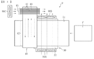
図2は、図1に示す冷却装置9の概略正面図、図3は、当該冷却装置9の概略平面図である。
冷却装置9は、記録材Pの裏面(片面印刷時における非画像面)を冷却する第1冷却部材としてのヒートシンク30と、記録材Pの表面(片面印刷時における画像面)を冷却する第2冷却部材としてのヒートパイプローラ40とを有する。
Hereinafter, the configuration of the cooling device according to the embodiment of the present invention will be described.
FIG. 2 is a schematic front view of the cooling device 9 shown in FIG. 1, and FIG. 3 is a schematic plan view of the cooling device 9.
The cooling device 9 is a heat sink 30 as a first cooling member that cools the back surface (non-image surface during single-sided printing) of the recording material P, and a second that cools the surface (image surface during single-sided printing) of the recording material P. And a heat pipe roller 40 as a cooling member.
図2に示すように、ヒートシンク30は、主搬送路26に沿って搬送される記録材Pの裏面側から熱を奪う受熱部32と、受熱部32で奪った熱を放熱する放熱部33と、剛性の高い補強部35とを有する。受熱部32、放熱部33及び補強部35は、それぞれ冷却装置9の正面側から背面側に渡って連続して設けられている。
As shown in FIG. 2, the heat sink 30 includes a heat receiving portion 32 that removes heat from the back surface side of the recording material P conveyed along the main conveyance path 26, and a heat radiating portion 33 that radiates the heat deprived by the heat receiving portion 32. And a stiffening portion 35 having high rigidity. The heat receiving portion 32, the heat radiating portion 33, and the reinforcing portion 35 are respectively provided continuously from the front side to the back side of the cooling device 9.
受熱部32は、平板状に形成され、主搬送路26側に配置される。受熱部32の主搬送路26側の平面が、記録材Pから熱を奪う受熱面(第1受熱面)32aである。放熱部33は、放熱部材としての複数の平板状のフィン31を有する。複数のフィン31は、受熱部32から受熱面32aとは反対側に延び、搬送媒体搬送方向(以下、単に「搬送方向」という。)に互いに間隔をあけて配置されている。補強部35は、放熱部33に対して搬送方向の上流側と下流側、すなわち放熱部33を介して互いに反対側に配置される。補強部35は、受熱部32からフィン31と同じ方向(受熱面32aとは反対側)に延びる側壁部36と、側壁部36から放熱部33とは反対側に突出する突出部37とを有する。側壁部36はフィン31と同様に受熱部32から延びる平板状の部分であるが、フィン31よりも搬送方向の厚さが厚く形成されているため(図2中、t1>t2)、フィン31よりも剛性が高い。
The heat receiving portion 32 is formed in a flat plate shape and is disposed on the main transport path 26 side. A flat surface on the main conveyance path 26 side of the heat receiving portion 32 is a heat receiving surface (first heat receiving surface) 32 a that takes heat from the recording material P. The heat radiation part 33 has a plurality of flat fins 31 as heat radiation members. The plurality of fins 31 extend from the heat receiving portion 32 to the side opposite to the heat receiving surface 32a, and are arranged at intervals from each other in the transport medium transport direction (hereinafter simply referred to as “transport direction”). The reinforcing portion 35 is disposed on the upstream side and the downstream side in the transport direction with respect to the heat radiating portion 33, that is, on the opposite side to each other via the heat radiating portion 33. The reinforcing portion 35 has a side wall portion 36 extending from the heat receiving portion 32 in the same direction as the fin 31 (opposite side to the heat receiving surface 32a) and a protruding portion 37 protruding from the side wall portion 36 to the opposite side of the heat radiating portion 33. . The side wall portion 36 is a flat plate-like portion extending from the heat receiving portion 32 in the same manner as the fin 31. However, since the thickness in the transport direction is larger than that of the fin 31 (t 1> t 2 in FIG. 2), the fin 31. More rigid than
また、ヒートシンク30には、フィン31の先端部側の開口部を覆う蓋部材79が設けられている。蓋部材79は、ヒートシンク30の正面側から背面側に渡って連続して設けられ、搬送方向の両端部が突出部37に固定されている。フィン31は蓋部材79と受熱部32と補強部35とによって囲まれている。このように、フィン31の周囲が囲まれることで、フィン31に沿って気流が通過する通気路34が形成されている。
The heat sink 30 is provided with a lid member 79 that covers the opening on the tip end side of the fin 31. The lid member 79 is provided continuously from the front side to the back side of the heat sink 30, and both end portions in the transport direction are fixed to the protruding portions 37. The fin 31 is surrounded by the lid member 79, the heat receiving portion 32, and the reinforcing portion 35. Thus, the air passage 34 through which the airflow passes along the fin 31 is formed by surrounding the periphery of the fin 31.
ヒートパイプローラ40は、主搬送路26に沿って搬送される記録材Pの表面側から熱を奪う受熱部42と、受熱部42で奪った熱を放熱する放熱部43とを有する。受熱部42は、円筒部材で構成され、主搬送路26に対向して配置される。主搬送路26と対向する受熱部42の外周面が、記録材Pから熱を奪う受熱面(第2受熱面)42aである。放熱部43は、放熱部材としての複数のリング状のフィン41を有する。複数のフィン41は、受熱部42を構成する円筒部材の一端部側の外周面に設けられ、互いに軸方向に間隔をあけて配置されている。
The heat pipe roller 40 includes a heat receiving part 42 that takes heat away from the surface side of the recording material P that is conveyed along the main conveying path 26, and a heat radiating part 43 that radiates heat taken by the heat receiving part 42. The heat receiving portion 42 is formed of a cylindrical member and is disposed to face the main transport path 26. The outer peripheral surface of the heat receiving portion 42 facing the main conveyance path 26 is a heat receiving surface (second heat receiving surface) 42 a that takes heat away from the recording material P. The heat radiating portion 43 has a plurality of ring-shaped fins 41 as heat radiating members. The plurality of fins 41 are provided on the outer peripheral surface on the one end portion side of the cylindrical member constituting the heat receiving portion 42, and are arranged at intervals in the axial direction.
図3に示すように、ヒートシンク30のフィン31の正面側(図の下側)と背面側(図の上側)には、それぞれ気流発生手段としての第1ファン80A及び第2ファン80Bが配置されている。正面側の第1ファン80Aは、ヒートシンク30の正面側からフィン31同士の間及びフィン31の周囲に形成された通気路34(図2参照)に向けて空気を送る。一方、背面側の第2ファン80Bは通気路34から空気を吸い込みヒートシンク30の背面側へ空気を排出する。
As shown in FIG. 3, a first fan 80 </ b> A and a second fan 80 </ b> B are disposed as airflow generating means on the front side (lower side in the figure) and the rear side (upper side in the figure) of the fins 31 of the heat sink 30. ing. The first fan 80 </ b> A on the front side sends air from the front side of the heat sink 30 toward the air passage 34 (see FIG. 2) formed between the fins 31 and around the fins 31. On the other hand, the second fan 80 </ b> B on the back side sucks air from the air passage 34 and discharges air to the back side of the heat sink 30.
また、ヒートパイプローラ40のフィン41の搬送方向の下流側にも、気流発生手段としての第3ファン80Cが配置されている。第3ファン80Cはフィン41同士の間に形成された通気路44に向けて空気を送り、空気は通気路44に沿って搬送方向の下流側から上流側に向かって流れる。なお、これとは反対に、第3ファン80Cをフィン41に対して搬送方向の上流側に配置し、上流側から下流側に向かって空気を送るようにしてもよい。第1ファン80A及び第2ファン80Bの気流発生方向と、第3ファン80Cの気流発生方向とは交差する方向である。
A third fan 80 </ b> C serving as an airflow generating unit is also disposed on the downstream side of the heat pipe roller 40 in the conveying direction of the fins 41. The third fan 80 </ b> C sends air toward the air passage 44 formed between the fins 41, and the air flows along the air passage 44 from the downstream side to the upstream side in the transport direction. On the other hand, the third fan 80C may be arranged on the upstream side in the transport direction with respect to the fins 41 so as to send air from the upstream side toward the downstream side. The airflow generation direction of the first fan 80A and the second fan 80B intersects the airflow generation direction of the third fan 80C.
また、図2に示すように、冷却装置9は、記録材Pを搬送する搬送部として、記録材Pを表面に担持して搬送する搬送ベルト51と、搬送ベルト51を回転駆動(表面移動)させるベルト駆動手段としての駆動ローラ52と、搬送ベルト51と対向する対向搬送部材としての2つのベルト対向ローラ61,62と、搬送ベルト51に対して搬送方向の上流側に配置された上流側搬送部材としての一対の上流側搬送ローラ63,64と、記録材Pを搬送方向に案内するガイド部材としての搬送ガイド65a〜65c,66とを有する。
As shown in FIG. 2, the cooling device 9 serves as a conveyance unit that conveys the recording material P, and conveys and conveys the conveyance belt 51 that carries the recording material P on the surface and rotates the conveyance belt 51 (surface movement). A driving roller 52 as a belt driving means to be driven, two belt facing rollers 61 and 62 as opposed conveying members opposed to the conveying belt 51, and upstream conveying arranged upstream of the conveying belt 51 in the conveying direction A pair of upstream conveyance rollers 63 and 64 as members, and conveyance guides 65a to 65c and 66 as guide members for guiding the recording material P in the conveyance direction are included.
搬送ベルト51は、ポリイミド等の樹脂で構成される無端状のベルト部材である。搬送ベルト51は、駆動ローラ52に加え3つの従動ローラ53〜55を含む複数のベルト張架部材によって張架される。駆動ローラ52がモータ等の駆動源によって回転駆動することで、搬送ベルト51は図2における反時計回りに回転駆動する。搬送ベルト51の外周面のうち、主搬送路26と対向する面が記録材Pと接触して記録材Pを搬送する搬送面である。
The conveyor belt 51 is an endless belt member made of a resin such as polyimide. The conveying belt 51 is stretched by a plurality of belt stretching members including three driven rollers 53 to 55 in addition to the driving roller 52. When the driving roller 52 is rotationally driven by a driving source such as a motor, the conveyance belt 51 is rotationally driven counterclockwise in FIG. Of the outer peripheral surface of the conveyance belt 51, the surface facing the main conveyance path 26 is a conveyance surface that contacts the recording material P and conveys the recording material P.
また、搬送ベルト51は、張力付与部材としてのテンションローラ56及びこれを付勢する付勢部材としてのバネ57によって所定の張力が付与される。本実施形態では、駆動ローラ52とこれと隣り合う従動ローラ55との間にテンションローラ56を配置することで、駆動ローラ52に対する搬送ベルト51の巻き付け角度が大きくなるようにしている。これにより、駆動ローラ52に対する搬送ベルト51の接触領域を大きく確保することができ、搬送ベルト51に対する駆動ローラ52のスリップを抑制できるようになる。
The conveyor belt 51 is given a predetermined tension by a tension roller 56 as a tension applying member and a spring 57 as a biasing member that biases the tension roller 56. In this embodiment, the tension roller 56 is disposed between the driving roller 52 and the driven roller 55 adjacent thereto, so that the winding angle of the conveying belt 51 with respect to the driving roller 52 is increased. Thereby, a large contact area of the conveying belt 51 with respect to the driving roller 52 can be secured, and slip of the driving roller 52 with respect to the conveying belt 51 can be suppressed.
ヒートシンク30は搬送ベルト51の内周側に配置されている。一方、ヒートパイプローラ40は、搬送ベルト51の外周面側に配置されている。すなわち、ヒートシンク30とヒートパイプローラ40は、搬送ベルト51に対して互いに反対側に配置されている。さらに言えば、本実施形態では、主搬送路26に対して、ヒートシンク30は下方、ヒートパイプローラ40は上方に配置されている。搬送ベルト51の内周面と接触するヒートシンク30における受熱部32の接触面が受熱面32aである。搬送ベルト51の外周面と接触するヒートパイプローラ40における受熱部42の接触面が受熱面42aである。また、ヒートパイプローラ40はヒートシンク30よりも搬送ベルト51に対して搬送方向の下流側で接触している。すなわち、ヒートパイプローラ40の受熱面42aはヒートシンク30の受熱面32aよりも搬送方向の下流側に配置されている。また、ヒートパイプローラ40のフィン41は、搬送ベルト51と干渉しないように、搬送ベルト51の搬送幅方向の外側(本実施形態では冷却装置9の背面側)に配置されている(図3参照)。
The heat sink 30 is disposed on the inner peripheral side of the conveyor belt 51. On the other hand, the heat pipe roller 40 is disposed on the outer peripheral surface side of the transport belt 51. That is, the heat sink 30 and the heat pipe roller 40 are arranged on the opposite sides with respect to the transport belt 51. Furthermore, in this embodiment, the heat sink 30 is disposed below and the heat pipe roller 40 is disposed above the main conveyance path 26. The contact surface of the heat receiving portion 32 in the heat sink 30 that contacts the inner peripheral surface of the conveyor belt 51 is the heat receiving surface 32a. A contact surface of the heat receiving portion 42 in the heat pipe roller 40 that contacts the outer peripheral surface of the conveyor belt 51 is a heat receiving surface 42a. The heat pipe roller 40 is in contact with the transport belt 51 on the downstream side in the transport direction with respect to the heat sink 30. That is, the heat receiving surface 42 a of the heat pipe roller 40 is disposed downstream of the heat receiving surface 32 a of the heat sink 30 in the transport direction. Further, the fins 41 of the heat pipe roller 40 are arranged outside the conveyance belt 51 in the conveyance width direction (in the present embodiment, on the back side of the cooling device 9) so as not to interfere with the conveyance belt 51 (see FIG. 3). ).
各ベルト対向ローラ61,62は、ヒートパイプローラ40よりも搬送方向の上流側で搬送方向に並び、ヒートシンク30の受熱面32aと搬送ベルト51との接触領域における搬送ベルト51の外周面に接触している。
The belt facing rollers 61 and 62 are arranged in the transport direction upstream of the heat pipe roller 40 in the transport direction, and contact the outer peripheral surface of the transport belt 51 in the contact area between the heat receiving surface 32a of the heat sink 30 and the transport belt 51. ing.
各上流側搬送ローラ63,64は、主搬送路26を挟んで互いに接触して配置される従動ローラと駆動ローラである。なお、主搬送路26に対して下方に配置される上流側搬送ローラ64が従動ローラで、上方に配置される上流側搬送ローラ63が駆動ローラとしてもよい。
The upstream-side transport rollers 63 and 64 are a driven roller and a drive roller that are arranged in contact with each other with the main transport path 26 interposed therebetween. The upstream conveyance roller 64 disposed below the main conveyance path 26 may be a driven roller, and the upstream conveyance roller 63 disposed above may be a driving roller.
各搬送ガイド65a〜65cは、搬送媒体搬送方向の上流側から下流側に向かって主搬送路26に接近するように傾斜するガイド面を有する。また、搬送ガイド65a〜65cのうち、搬送方向の最上流側に配置される搬送ガイド65aは上流側搬送ローラ63と(上流側の)ベルト対向ローラ62との間に配置され、その下流側に配置される搬送ガイド65bはベルト対向ローラ61,62同士の間に配置され、さらに下流(最下流)に配置される搬送ガイド65cは(下流側の)ベルト対向ローラ61とヒートパイプローラ40の受熱部42との間に配置されている。本実施形態では、これらの搬送ガイド65a〜65cは一体的に構成されているが、それぞれ別体で構成してもよい。
Each of the transport guides 65a to 65c has a guide surface that is inclined so as to approach the main transport path 26 from the upstream side to the downstream side in the transport medium transport direction. Of the transport guides 65a to 65c, the transport guide 65a disposed on the most upstream side in the transport direction is disposed between the upstream transport roller 63 and the (upstream) belt facing roller 62, and on the downstream side thereof. The conveyance guide 65b disposed is disposed between the belt facing rollers 61 and 62, and the conveyance guide 65c disposed further downstream (most downstream) receives heat of the belt facing roller 61 and the heat pipe roller 40 (on the downstream side). It arrange | positions between the parts 42. FIG. In the present embodiment, these conveyance guides 65a to 65c are integrally configured, but may be configured separately.
搬送ガイド66は、主搬送路26に対して下方であって、上流側搬送ローラ64と搬送ベルト51との間に配置されている。また、この搬送ガイド66は、搬送方向の上流側から下流側に向かって主搬送路26に接近するように傾斜するガイド面を有する。搬送ガイド66により、主搬送路26と対向する搬送ベルト51又はその上方に向けて記録材Pが案内される。
The conveyance guide 66 is disposed below the main conveyance path 26 and between the upstream conveyance roller 64 and the conveyance belt 51. The transport guide 66 has a guide surface that is inclined so as to approach the main transport path 26 from the upstream side to the downstream side in the transport direction. The recording material P is guided by the conveyance guide 66 toward the conveyance belt 51 facing the main conveyance path 26 or above the conveyance belt 51.
続いて、図2を参照しつつ冷却装置9の基本的動作について説明する。
定着装置8から冷却装置9へ記録材Pが搬送されると、回転する一対の上流側搬送ローラ63,64によって、記録材Pは搬送ベルト51へ搬送される。搬送ベルト51へ搬送された記録材Pは搬送ベルト51上に担持され、搬送ベルト51とこれと一緒に従動回転する各ベルト対向ローラ61,62によって搬送される。このとき、記録材Pがヒートシンク30の受熱面32aを通過することで、受熱面32aによって記録材Pの熱が裏面側から奪われ、記録材Pが冷却される。また、受熱面32aによって奪われた熱は、フィン31へと熱移動し、ファン80A,80Bによって、強制的に空気と一緒に機外(冷却装置9の外又は画像形成装置本体200の外)へと排出される。
Next, the basic operation of the cooling device 9 will be described with reference to FIG.
When the recording material P is transported from the fixing device 8 to the cooling device 9, the recording material P is transported to the transport belt 51 by a pair of rotating upstream transport rollers 63 and 64. The recording material P transported to the transport belt 51 is carried on the transport belt 51 and is transported by the transport belt 51 and the respective belt facing rollers 61 and 62 that are driven to rotate together with the transport belt 51. At this time, when the recording material P passes through the heat receiving surface 32a of the heat sink 30, the heat of the recording material P is taken away from the back surface side by the heat receiving surface 32a, and the recording material P is cooled. Further, the heat taken away by the heat receiving surface 32a is transferred to the fins 31, and is forced out of the apparatus together with air by the fans 80A and 80B (outside the cooling device 9 or outside the image forming apparatus main body 200). Is discharged.
記録材Pは、ヒートシンク30の受熱面32aを通過後、搬送ベルト51とこれと一緒に従動回転するヒートパイプローラ40とによって搬送される。このとき、記録材Pがヒートパイプローラ40の受熱面42aと接触することで、記録材Pの熱が表面側から奪われ、記録材Pが冷却される。また、受熱部42によって奪われた熱は、フィン41から空気中に放熱される。詳しくは、ヒートパイプローラ40を構成する円筒部材内に収容される液状の冷媒が、記録材Pからの熱で気化し、円筒部材内の中央の流体流路を通ってフィン41側へ移動する。フィン41が設けられた部分ではファン80Cから送られる気流によって冷やされ、この冷やされた部分の内面に冷媒が触れることで熱交換される。これにより、冷媒は凝集して液状になり、円筒部材内の流体流路を通って再び受熱部42側に移動する。このように、冷媒は、気化と液化(凝集)とを繰り返すことで、受熱部42側から放熱部43側へ熱を移動させて放熱する。
After passing through the heat receiving surface 32 a of the heat sink 30, the recording material P is transported by the transport belt 51 and the heat pipe roller 40 that rotates along with the transport belt 51. At this time, when the recording material P comes into contact with the heat receiving surface 42a of the heat pipe roller 40, the heat of the recording material P is taken from the surface side, and the recording material P is cooled. Further, the heat taken away by the heat receiving portion 42 is radiated from the fins 41 into the air. Specifically, the liquid refrigerant accommodated in the cylindrical member constituting the heat pipe roller 40 is vaporized by the heat from the recording material P, and moves to the fin 41 side through the central fluid passage in the cylindrical member. . The portion where the fins 41 are provided is cooled by the airflow sent from the fan 80C, and heat is exchanged when the refrigerant touches the inner surface of the cooled portion. As a result, the refrigerant aggregates into a liquid state and moves to the heat receiving portion 42 side again through the fluid flow path in the cylindrical member. As described above, the refrigerant repeats vaporization and liquefaction (aggregation), thereby moving the heat from the heat receiving portion 42 side to the heat radiating portion 43 side to radiate heat.
上記のように、本実施形態に係る冷却装置9では、ヒートシンク30とヒートパイプローラ40によって記録材Pを表側と裏側とから冷却するので、記録材Pを効果的に冷却することができる。これにより、記録材Pが機外に排出されてストックされた際に、軟化したトナーが別の記録材Pに貼りつくいわゆるブロッキング等の不具合を防止することができる。
As described above, in the cooling device 9 according to this embodiment, since the recording material P is cooled from the front side and the back side by the heat sink 30 and the heat pipe roller 40, the recording material P can be effectively cooled. Thereby, when the recording material P is discharged out of the apparatus and stocked, it is possible to prevent problems such as so-called blocking in which the softened toner sticks to another recording material P.
なお、画像形成装置に搭載される装置として、記録材を加熱した後に冷却して光沢を付与する光沢付与装置があるが、本発明に係る冷却装置は斯かる光沢付与装置とは構成及び作用効果の点において全く別異のものである。すなわち、本発明に係る冷却装置は、第1冷却部材と第2冷却部材との間では勿論のこと、第1冷却部材の搬送方向上流側や第2冷却部材の搬送方向下流側においても搬送媒体を加熱する加熱部材を備えていない。要するに、本発明に係る冷却装置は、搬送媒体を加熱することなく冷却する冷却装置である。
As an apparatus mounted on the image forming apparatus, there is a gloss imparting apparatus that gives a gloss by heating after the recording material is heated. The cooling apparatus according to the present invention is different from the gloss imparting apparatus in configuration and function and effect. Is completely different. That is, the cooling device according to the present invention is not only between the first cooling member and the second cooling member, but also on the upstream side in the transport direction of the first cooling member and the downstream side in the transport direction of the second cooling member. The heating member which heats is not provided. In short, the cooling device according to the present invention is a cooling device that cools the conveyance medium without heating.
上記のように、本実施形態では、第2冷却部材としてヒートパイプローラ40を用いているため、ヒートパイプローラ40の外周面に搬送ベルト51を巻き付けることで、両部材の搬送方向の接触幅すなわち受熱面42aを大きく確保することができる。また、ヒートパイプローラ40に対する搬送ベルト51の巻き付け角度を調整することで、記録材Pの搬送方向を変更することができるため、搬送方向を変更するための搬送ガイドを省略することができ、レイアウト性が向上する。また、搬送ガイドを用いなくてもヒートパイプローラ40によって搬送方向を変更できるため、搬送方向変更時における、搬送ガイドと記録材Pの画像面との擦れによる画像不良が生じることもない。
As described above, since the heat pipe roller 40 is used as the second cooling member in the present embodiment, the contact width in the transport direction of both members, that is, by winding the transport belt 51 around the outer peripheral surface of the heat pipe roller 40, that is, A large heat receiving surface 42a can be secured. Further, since the conveyance direction of the recording material P can be changed by adjusting the winding angle of the conveyance belt 51 with respect to the heat pipe roller 40, a conveyance guide for changing the conveyance direction can be omitted, and the layout can be omitted. Improves. Further, since the transport direction can be changed by the heat pipe roller 40 without using the transport guide, image defects due to rubbing between the transport guide and the image surface of the recording material P do not occur when the transport direction is changed.
一方、第1冷却部材は、平面状の受熱面32aを有するヒートシンク30であるため、記録材Pを直線状に搬送しながら冷却しつつ、ヒートパイプローラ40へと案内できる。特に、本実施形態では、ヒートシンク30の受熱面32aのほぼ延長線上にヒートパイプローラ40の受熱面42aの搬送方向の上流端部(搬送ベルト51の巻き付け開始位置)があるので、記録材Pをスムーズに搬送することができる。
On the other hand, since the first cooling member is the heat sink 30 having the planar heat receiving surface 32a, the recording material P can be guided to the heat pipe roller 40 while being cooled while being conveyed linearly. In particular, in the present embodiment, since the upstream end portion (winding start position of the conveyor belt 51) of the heat receiving surface 42a of the heat pipe roller 40 is located substantially on the extended line of the heat receiving surface 32a of the heat sink 30, the recording material P is It can be transported smoothly.
また、ヒートシンク30の受熱面32aがヒートパイプローラ40の受熱面42aよりも搬送方向の上流側に配置されているため、記録材Pにカールが生じにくい。すなわち、定着装置8から排出された直後の記録材Pは高温状態となっているが、まず、記録材Pはヒートシンク30の受熱面32aに沿って負荷の少ない平面状態で搬送されつつ冷却される。その後、記録材Pは、曲面状の受熱面42aに沿って湾曲させられながら搬送されるが、このとき記録材Pはヒートシンク30によってある程度冷却されて安定した状態となっているので、曲率負荷の影響を受けにくくカールが生じにくい。
Further, since the heat receiving surface 32a of the heat sink 30 is arranged on the upstream side in the transport direction with respect to the heat receiving surface 42a of the heat pipe roller 40, the recording material P is hardly curled. That is, the recording material P immediately after being discharged from the fixing device 8 is in a high temperature state, but first, the recording material P is cooled while being transported along a heat receiving surface 32a of the heat sink 30 in a flat state with a small load. . After that, the recording material P is conveyed while being curved along the curved heat receiving surface 42a. At this time, the recording material P is cooled to some extent by the heat sink 30 and is in a stable state. Less susceptible to curling.
また、ヒートシンク30とヒートパイプローラ40の各受熱部32,42が搬送方向にずれて互いに離れた位置に配置されているため、例えば図4(a)(b)に示す例のように受熱部32,42同士が対向して(搬送ベルト51を介して互いに接触するように)配置された場合に比べて、それぞれの受熱面32a,42aを大きく確保できる。
In addition, since the heat receiving portions 32 and 42 of the heat sink 30 and the heat pipe roller 40 are arranged at positions that are shifted from each other in the transport direction and separated from each other, for example, as shown in FIGS. 4A and 4B, Each of the heat receiving surfaces 32a and 42a can be ensured larger than the case where the members 32 and 42 are arranged to face each other (so as to contact each other via the conveyor belt 51).
本実施形態に係るヒートパイプローラ40のフィン41は、受熱部42の外周面よりも外径が大きい。このため、仮に、図5に示すように、第1冷却部材も同様のヒートパイプローラ40で構成すると、両ヒートパイプローラ40のフィン41同士の干渉を回避するために、両ヒートパイプローラ40を搬送方向に遠ざけて配置しなければならない。これに対し、本実施形態のように、第1冷却部材にヒートパイプローラ40とは異なるヒートシンク30を用いることで、ヒートシンク30とヒートパイプローラ40を搬送方向に接近させて配置することができる。具体的には、ヒートシンク30の受熱面32aの搬送方向の下流端部を、ヒートパイプローラ40のフィン41の外周面よりも径方向内側に入り込むくらいまで接近させて配置できる(図2参照)。これにより、搬送方向の小型化を図れると共に、両受熱部32,42間で記録材Pが冷却されない領域Z(図2、図5参照)が短くなるため、冷却性能が向上する。
The fin 41 of the heat pipe roller 40 according to this embodiment has an outer diameter larger than the outer peripheral surface of the heat receiving portion 42. For this reason, as shown in FIG. 5, if the first cooling member is also composed of the same heat pipe roller 40, the two heat pipe rollers 40 are arranged to avoid interference between the fins 41 of the two heat pipe rollers 40. Must be placed away from the transport direction. On the other hand, as in this embodiment, by using the heat sink 30 different from the heat pipe roller 40 as the first cooling member, the heat sink 30 and the heat pipe roller 40 can be arranged close to each other in the transport direction. Specifically, the downstream end portion in the transport direction of the heat receiving surface 32a of the heat sink 30 can be disposed so as to approach the radially inner side of the outer peripheral surface of the fin 41 of the heat pipe roller 40 (see FIG. 2). Thereby, the size in the transport direction can be reduced, and the area Z (see FIGS. 2 and 5) where the recording material P is not cooled between the heat receiving portions 32 and 42 is shortened, so that the cooling performance is improved.
また、図6に示す例のように、両冷却部にヒートパイプローラ40を用いた構成において、それぞれのフィン41の位置を前後方向にずらして配置すると、図5に比べて、両ヒートパイプローラ40のフィン41の干渉を回避しつつ、受熱部42同士を搬送方向に接近させて配置することが可能である。しかし、搬送ベルト51の幅方向の一方及び他方にそれぞれフィン41が突出する。そのため、冷却装置9又は画像形成装置本体200が前後方向に大きくなる。これに対し、本実施形態のように、第1冷却部材にヒートパイプローラ40とは異なるヒートシンク30を用いることで、冷却装置9又は画像形成装置本体200の前後方向の大きさを小さくできる。
Further, as in the example shown in FIG. 6, in the configuration in which the heat pipe rollers 40 are used in both cooling units, when the positions of the fins 41 are shifted in the front-rear direction, both heat pipe rollers are compared with FIG. 5. It is possible to arrange the heat receiving portions 42 close to each other in the transport direction while avoiding interference between the 40 fins 41. However, the fins 41 protrude from one side and the other side of the conveyance belt 51 in the width direction. Therefore, the cooling device 9 or the image forming apparatus main body 200 becomes large in the front-rear direction. On the other hand, the size of the cooling device 9 or the image forming apparatus main body 200 in the front-rear direction can be reduced by using the heat sink 30 different from the heat pipe roller 40 as the first cooling member as in the present embodiment.
図7は、本実施形態に係る画像形成装置の概略外観図である。
図7に示すように、画像形成装置本体200の正面には、開閉可能な扉201が設けられている。
FIG. 7 is a schematic external view of the image forming apparatus according to the present embodiment.
As shown in FIG. 7, an openable / closable door 201 is provided in front of the image forming apparatus main body 200.
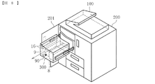
図8は、上記扉201を開放して引出ユニット300を引き出した状態を示す図である。
図8に示すように、扉201を開放することによって、画像形成装置本体200の開放された箇所から、内部に収容されている引出ユニット300を手前側(正面側)へ引き出すことができる。詳しくは、扉201を開放してから、引出ユニット300の前側面に設けられたロック操作部としてのレバー90を回転操作し、画像形成装置本体200に対する引出ユニット300のロック状態を解除することで、引出ユニット300を引き出すことができる。この引出ユニット300は、定着装置8、冷却装置9、排出ローラ16及び搬送媒体搬送路25の一部(主搬送路26、反転路及27及び再供給路28の各一部)が一体的に構成されたものである。このように、これらの装置及び搬送媒体搬送路の一部をユニットとして画像形成装置本体200の外部に引き出せるように構成することで、メンテナンス作業や紙詰まり処理が行いやすくなる。
FIG. 8 is a view showing a state where the door 201 is opened and the drawer unit 300 is pulled out.
As shown in FIG. 8, by opening the door 201, the drawer unit 300 accommodated in the image forming apparatus main body 200 can be pulled out to the near side (front side) from the opened position. Specifically, after the door 201 is opened, a lever 90 as a lock operation unit provided on the front side surface of the drawer unit 300 is rotated to release the locked state of the drawer unit 300 with respect to the image forming apparatus main body 200. The drawer unit 300 can be pulled out. In the drawing unit 300, the fixing device 8, the cooling device 9, the discharge roller 16, and a part of the transport medium transport path 25 (a part of the main transport path 26, the reverse path 27, and the resupply path 28) are integrated. It is configured. As described above, by configuring such a part of the apparatus and the conveyance medium conveyance path as a unit so that the apparatus can be pulled out of the image forming apparatus main body 200, maintenance work and paper jam processing can be easily performed.
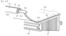
本実施形態では、図9に示すように、ヒートシンク30のフィン31の先端部(受熱面32a側とは反対側の端部)31aが水平方向に対して斜めに並ぶように配置されている。しかしながら、このような形状のヒートシンク30に限らず、図10に示す例のように、フィン31の先端部が水平方向に並ぶように配置されてもよい。この場合、各フィン31が同じ長さで同様の放熱効果を有するので、搬送方向の上流側から下流側に向かって均一な冷却効果が得られる。
In the present embodiment, as shown in FIG. 9, the tips 31 of the fins 31 of the heat sink 30 (ends opposite to the heat receiving surface 32 a) 31 a are arranged so as to be obliquely arranged in the horizontal direction. However, the heat sink 30 is not limited to such a shape, and the tips of the fins 31 may be arranged in the horizontal direction as in the example shown in FIG. In this case, since the fins 31 have the same length and have the same heat dissipation effect, a uniform cooling effect can be obtained from the upstream side to the downstream side in the transport direction.
これに対し、本実施形態のように、ヒートシンク30のフィン31の先端部31aを斜めに並べている場合は、装置の小型化が可能である。すなわち、フィン31の先端部31aを斜めに並べることで、搬送ベルト51におけるヒートシンク30の下方で張架される部分51aをフィン31の先端部31aに沿って斜めに配置することができるので、冷却装置9の下部近傍に上記レバー90の支軸91を配置するスペース(図9中の点線Fで囲まれる空間)を確保することができる。これにより、冷却装置9の小型化を図ることができる。また、他の構造物も冷却装置9の下部に接近させて配置しやすくなるため、図10に示す例に比べて、冷却装置9の下方のデッドスペース(図10の点線で囲まれる空間)を少なくすることができる。なお、本実施形態において、冷却装置9の下部近傍に確保された支軸91の配置スペースとは、小型化を図るべく支軸91を冷却装置9に接近させて配置できる空間であって、フィン31の先端部31aを斜めに並べることで得られるようになる空間である。具体的には、搬送ベルト51のヒートシンク30の下方で張架される部分51aと、当該部分51aの最下端部Yを通る水平面Xとの間の領域(図9中の点線Fで囲まれる空間)である。この領域内に支軸91の少なくとも一部を配置することで、小型化を図りつつ、他の構造物を冷却装置9の下部に接近させて配置しやすくなる。
On the other hand, when the tip portions 31a of the fins 31 of the heat sink 30 are arranged obliquely as in the present embodiment, the apparatus can be downsized. That is, by arranging the tip portions 31a of the fins 31 obliquely, the portion 51a stretched below the heat sink 30 in the conveyor belt 51 can be disposed obliquely along the tip portions 31a of the fins 31. A space for placing the support shaft 91 of the lever 90 in the vicinity of the lower portion of the device 9 (a space surrounded by a dotted line F in FIG. 9) can be secured. Thereby, size reduction of the cooling device 9 can be achieved. In addition, since other structures can be easily placed close to the lower portion of the cooling device 9, a dead space (a space surrounded by a dotted line in FIG. 10) below the cooling device 9 is smaller than the example shown in FIG. 10. Can be reduced. In the present embodiment, the arrangement space of the support shaft 91 secured in the vicinity of the lower portion of the cooling device 9 is a space in which the support shaft 91 can be placed close to the cooling device 9 in order to reduce the size. This is a space that can be obtained by arranging the tip portions 31a of 31 at an angle. Specifically, a region (a space surrounded by a dotted line F in FIG. 9) between a portion 51a stretched below the heat sink 30 of the conveyor belt 51 and a horizontal plane X passing through the lowermost end Y of the portion 51a. ). By disposing at least a part of the support shaft 91 in this region, it becomes easy to dispose other structures close to the lower portion of the cooling device 9 while reducing the size.
さらに小型化を図るため、本実施形態では、搬送方向の上流側に配置される2つの従動ローラ53,54がヒートシンク30の突出部37を挟むように配置されている。すなわち、各従動ローラ53,54の少なくとも一部を、突出部37の先端部よりもヒートシンク30側であって、各従動ローラ53,54が配置される側のヒートシンク30の端面と対向する範囲内(図9中の点線Gで囲まれる空間内)に配置することで、各従動ローラ53,54を突出部37に対して近接して配置し、小型化を図れる。
In order to further reduce the size, in this embodiment, the two driven rollers 53 and 54 disposed on the upstream side in the transport direction are disposed so as to sandwich the protruding portion 37 of the heat sink 30. That is, at least a part of each driven roller 53, 54 is within the range facing the end surface of the heat sink 30 on the side where the driven rollers 53, 54 are arranged, closer to the heat sink 30 than the tip of the protrusion 37. By arranging in the space surrounded by the dotted line G in FIG. 9, the driven rollers 53 and 54 are arranged close to the projecting portion 37, and the size can be reduced.
本実施形態では、フィン31の受熱面32aと交差する方向の長さ(受熱部32に接続されるフィン31の根元部から先端部31aまでの長さ)が、主搬送路26の搬送方向の上流側から下流側に向かって短くなるように構成されている。フィン31は長いほど放熱性が高まる。従って、本実施形態では、搬送方向の上流側でフィン31を長くすることでヒートシンク30の冷却性能を高め、記録材Pの熱量が多い上流側で記録材Pを効果的に冷却することが可能である。
In the present embodiment, the length of the fin 31 in the direction intersecting the heat receiving surface 32a (the length from the root portion of the fin 31 connected to the heat receiving portion 32 to the tip portion 31a) is the length in the conveying direction of the main conveying path 26. It is comprised so that it may become short toward the downstream from the upstream. The longer the fins 31, the higher the heat dissipation. Therefore, in this embodiment, the cooling performance of the heat sink 30 can be improved by elongating the fins 31 on the upstream side in the transport direction, and the recording material P can be effectively cooled on the upstream side where the amount of heat of the recording material P is large. It is.
また、各フィン31の先端部31aの位置を異ならせ、搬送ベルト51を斜めに配置することで、冷却装置9の下方に配置される再供給路28を冷却装置9や定着装置8との干渉を回避しつつこれらに接近させて配置することができる。本実施形態では、再供給路28がその搬送方向の上流側で上方へ膨らむように形成されているため、再供給路28を全体的に定着装置8や冷却装置9の方へ接近させると、特に再供給路28の上方へ膨らむ部分が冷却装置9と干渉する可能性がある。そこで、この再供給路28の上方へ膨らむ部分との干渉を回避するため、当該部分の形状に対応してフィン31の先端部31aの位置(受熱面32aからの距離)を搬送方向に渡って異ならせ搬送ベルト51を斜めに配置している。本実施形態に係る再供給路28は、冷却装置9の下方にて搬送方向の上流側から下流側に向かって下方へ傾斜する傾斜部280(図9参照)を有するが、この傾斜部280の傾斜方向に対応して、フィン31の先端部31a及び搬送ベルト51を再供給路28の搬送方向の上流側から下流側に向かって下方へ傾斜するように配置している。
Further, the positions of the tip portions 31 a of the fins 31 are made different, and the conveyor belt 51 is arranged obliquely, so that the resupply path 28 arranged below the cooling device 9 interferes with the cooling device 9 and the fixing device 8. It is possible to place them close to these while avoiding the above. In this embodiment, since the resupply path 28 is formed so as to bulge upward on the upstream side in the conveying direction, when the resupply path 28 is moved closer to the fixing device 8 and the cooling device 9 as a whole, In particular, a portion that swells upward in the resupply path 28 may interfere with the cooling device 9. Therefore, in order to avoid interference with the portion that swells upward in the resupply path 28, the position of the tip portion 31a of the fin 31 (distance from the heat receiving surface 32a) in the transport direction corresponds to the shape of the portion. The conveying belt 51 is arranged obliquely. The resupply path 28 according to the present embodiment includes an inclined portion 280 (see FIG. 9) that is inclined downward from the upstream side to the downstream side in the transport direction below the cooling device 9. Corresponding to the inclination direction, the tip portions 31a of the fins 31 and the conveyor belt 51 are arranged so as to incline downward from the upstream side in the conveyance direction of the resupply path 28 toward the downstream side.
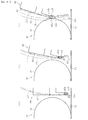
ここで、再供給路28を上方へ膨らむように形成している理由について説明する。例えば、図11(a)に示す構成において、画像形成装置の小型化を図るために、反転路27と再供給路28との上下方向の間隔W1を小さくして同図(b)に示す間隔W2にすると、反転路27から再供給路28への進入路の曲率を大きくしなければならなくなる(曲率半径がR1からR2へ小さくなる。)。この場合、記録材Pに対する搬送負荷が大きくなるため、記録材Pの搬送性が低下する可能性がある。そこで、本実施形態では、記録材Pの良好な搬送性と小型化を実現するため、図11(c)に示すように、再供給路28をその搬送方向の上流側で上方へ膨らむように形成している。これにより、反転路27と再供給路28との間隔を小さい間隔(W2)に維持しつつ、再供給路28への進入路の曲率を小さい曲率(大きい曲率半径R1)にすることが可能となる。
Here, the reason why the resupply path 28 is formed so as to expand upward will be described. For example, in the configuration shown in FIG. 11A, in order to reduce the size of the image forming apparatus, the vertical interval W1 between the reversing path 27 and the resupply path 28 is reduced and the distance shown in FIG. When W2, the curvature of the approach path from the reversing path 27 to the resupply path 28 must be increased (the radius of curvature decreases from R1 to R2). In this case, since the conveyance load with respect to the recording material P becomes large, the conveyance property of the recording material P may deteriorate. Therefore, in the present embodiment, in order to realize good transportability and downsizing of the recording material P, as shown in FIG. 11C, the resupply path 28 is swelled upward on the upstream side in the transport direction. Forming. Thereby, it is possible to make the curvature of the approach path to the resupply path 28 a small curvature (large curvature radius R1) while maintaining the distance between the reversing path 27 and the resupply path 28 at a small interval (W2). Become.
上記のように、良好な搬送性と小型化の実現のために再供給路28を上方へ膨らむように形成すると、再供給路28が冷却装置9と干渉するといった課題が新たに発生する。一方、これを回避するために再供給路28を全体的に下げて配置すると、小型化を実現し難くなる。そこで、本実施形態では、フィン31の先端部31aの位置を搬送方向に渡って異ならせ搬送ベルト51を斜めに配置することで、冷却装置9に対する再供給路28の干渉を回避しつつ互いに接近させて配置できるようにしている。
As described above, if the resupply path 28 is formed so as to bulge upward in order to realize good transportability and downsizing, a new problem arises that the resupply path 28 interferes with the cooling device 9. On the other hand, if the resupply path 28 is lowered and disposed in order to avoid this, it is difficult to achieve downsizing. Therefore, in the present embodiment, the positions of the tip portions 31a of the fins 31 are varied in the transport direction, and the transport belt 51 is disposed obliquely, thereby approaching each other while avoiding interference of the resupply path 28 with the cooling device 9. So that they can be placed.
上記のように、ヒートシンクのフィン31はその長さが主搬送路26における搬送方向の上流側から下流側に向かって次第に短くなるように構成されているため、図12に示す如くヒートシンク30の放熱部33は全体として略台形の外郭を呈する。一方、ヒートシンク30の手前側と奥側に配置されるファン80A,80Bはその外郭が略正方形に形成されている。このように、ヒートシンク30の放熱部33とファン80A,80Bのそれぞれの外郭形状は一致しない。このため、送風用のファン80Aからヒートシンク30への気流及びヒートシンク30から吸引用のファン80Bへの気流を確実に誘導できるように、ヒートシンク30と各ファン80A,80Bとの間には、流路形成部材としてのダクトを配置している。
As described above, since the length of the fin 31 of the heat sink gradually decreases from the upstream side in the transport direction in the main transport path 26 toward the downstream side, the heat dissipation of the heat sink 30 as shown in FIG. The part 33 exhibits a substantially trapezoidal outline as a whole. On the other hand, the outer sides of the fans 80A and 80B arranged on the near side and the far side of the heat sink 30 are formed in a substantially square shape. As described above, the outer shapes of the heat radiating portion 33 of the heat sink 30 and the fans 80A and 80B do not match. Therefore, a flow path is provided between the heat sink 30 and each of the fans 80A and 80B so that the air flow from the fan 80A for blowing to the heat sink 30 and the air flow from the heat sink 30 to the suction fan 80B can be reliably induced. A duct as a forming member is arranged.
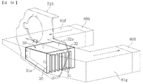
図13は、送風用のファン80Aに接続されるダクトを示す。
なお、吸引用のファン80Bに接続されるダクトも同様に構成されているので、ここでは送風用のファン80Aに接続されるダクトを例にその構成について説明する。
FIG. 13 shows a duct connected to the fan 80A for blowing air.
Since the duct connected to the suction fan 80B is configured in the same manner, the configuration will be described here taking the duct connected to the blower fan 80A as an example.
流路形成部材としてのダクトは、ファン80Aとヒートシンク30との間に配置される第1流路形成部材としての内側ダクト81と、内側ダクト81よりも機外側に配置される第2流路形成部材としての外側ダクト82とを有する。送風用のファン80Aによって生じる気流は、外側ダクト82、内側ダクト81の順に通過してヒートシンク30へ誘導される。なお、吸引用のファン80Bによって生じる気流は、反対に、内側ダクト81、外側ダクト82の順に通過して機外に排出される。
The duct as the flow path forming member includes an inner duct 81 as the first flow path forming member disposed between the fan 80A and the heat sink 30, and a second flow path formed at the outer side of the inner duct 81. And an outer duct 82 as a member. The airflow generated by the blower fan 80 </ b> A passes through the outer duct 82 and the inner duct 81 in this order and is guided to the heat sink 30. On the contrary, the air flow generated by the suction fan 80B passes through the inner duct 81 and the outer duct 82 in this order and is discharged outside the apparatus.
図14は、内側ダクト81をファン80A側から見た正面図、図15は、内側ダクト81をヒートシンク30側から見た背面図、図16は、内側ダクト81を図13における右側から見た側面図である。
内側ダクト81のファン80A側の開口部81aとヒートシンク30側の開口部81bは、互いに形状が異なる。具体的に、ファン80A側の開口部81aは、ファン80Aの外郭形状(図14中の二点鎖線参照)に対応して略正方形に形成されている。一方、ヒートシンク30側の開口部81bは、ヒートシンク30の放熱部33の外郭形状(図15中の二点鎖線参照)に対応して略台形に形成されている。具体的に、ヒートシンク30側の開口部81bは、互いに平行をなすように上下方向に延びる右辺部811及び左辺部812と、これらに対して直交する方向に延びる上辺部813と、上辺部813に対して傾斜するように延びる下辺部(傾斜辺部)814とで構成される。
14 is a front view of the inner duct 81 viewed from the fan 80A side, FIG. 15 is a rear view of the inner duct 81 viewed from the heat sink 30 side, and FIG. 16 is a side view of the inner duct 81 viewed from the right side in FIG. FIG.
The opening 81a on the fan 80A side and the opening 81b on the heat sink 30 side of the inner duct 81 have different shapes. Specifically, the opening 81a on the fan 80A side is formed in a substantially square shape corresponding to the outer shape of the fan 80A (see the two-dot chain line in FIG. 14). On the other hand, the opening 81b on the heat sink 30 side is formed in a substantially trapezoidal shape corresponding to the outer shape of the heat radiating portion 33 of the heat sink 30 (see the two-dot chain line in FIG. 15). Specifically, the opening 81b on the heat sink 30 side includes a right side portion 811 and a left side portion 812 that extend in the vertical direction so as to be parallel to each other, an upper side portion 813 that extends in a direction orthogonal to these, and an upper side portion 813. And a lower side portion (inclined side portion) 814 extending so as to be inclined.
ここで、ファン80A(及びファン80B)は、ヒートシンク30への気流の流量を確保するため放熱部33よりも大きいファンで構成されている。具体的には、ファン80A(及びファン80B)の上下方向の長さL1が、放熱部33のうちで最も長いフィン31の長さL2よりも長い(図12参照)。このため、内側ダクト81は、ファン80A側の開口部80aの方がヒートシンク30側の開口部80bよりも開口面積が大きくなるように形成されている。従って、内側ダクト81は、開口面積の大きいファン80A側の開口部81aから開口面積の小さいヒートシンク30側の開口部81bに向かって断面積が小さくなる流路縮小部81cを有する(図16参照)。言い換えれば、ヒートシンク30側の開口部81bからファン80A側の開口部81aに向かって断面積が大きくなる流路拡大部81cを有する。
Here, the fan 80 </ b> A (and the fan 80 </ b> B) is configured by a fan that is larger than the heat radiating unit 33 in order to ensure the flow rate of the airflow to the heat sink 30. Specifically, the length L1 in the vertical direction of the fan 80A (and the fan 80B) is longer than the length L2 of the longest fin 31 in the heat radiating section 33 (see FIG. 12). For this reason, the inner duct 81 is formed so that the opening area 80a on the fan 80A side has a larger opening area than the opening 80b on the heat sink 30 side. Accordingly, the inner duct 81 has a flow path reducing portion 81c whose sectional area decreases from the opening portion 81a on the fan 80A side having a large opening area toward the opening portion 81b on the heat sink 30 side having a small opening area (see FIG. 16). . In other words, the flow path expanding portion 81c has a cross-sectional area that increases from the opening 81b on the heat sink 30 side toward the opening 81a on the fan 80A side.
また、内側ダクト81は、ファン80Aが嵌め込まれる嵌め込み部81dを有する。嵌め込み部81dは、ファン80Aの外郭形状に対応して略矩形の枠体で構成されている。嵌め込み部81dの縁には、内側ダクト81を上記引出ユニット300のフレームに固定するネジ等の固定部材を挿入するための孔部81eが形成されている。
The inner duct 81 has a fitting portion 81d into which the fan 80A is fitted. The fitting portion 81d is configured by a substantially rectangular frame corresponding to the outer shape of the fan 80A. A hole 81e for inserting a fixing member such as a screw for fixing the inner duct 81 to the frame of the drawer unit 300 is formed at the edge of the fitting portion 81d.
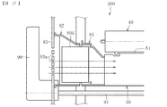
図17は、引出ユニット300をレバー90の付近で切断した概略断面図である。図17において、紙面に直交する手前側が搬送方向上流側、奥側が搬送方向下流側である。
図17に示すように、送風用のファン80Aとレバー90との間には、カバー部材83が配置されている。
FIG. 17 is a schematic cross-sectional view of the drawer unit 300 cut in the vicinity of the lever 90. In FIG. 17, the near side orthogonal to the paper surface is the upstream side in the transport direction, and the far side is the downstream side in the transport direction.
As shown in FIG. 17, a cover member 83 is disposed between the fan 80 </ b> A for blowing air and the lever 90.
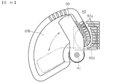
図18は、カバー部材83の正面図である。
図18に示すように、カバー部材83には、ファン80Aと対向する位置に複数の通気孔83aが形成されている。ファン80Aが駆動すると、通気孔83aを通して外部の空気を内側へ流入させることができ、ヒートシンク30に確実に気流を発生させることができる(図17中の矢印参照)。また、カバー部材83には、作業者がレバー90を把持した際にカバー部材83に手が接触するのを回避するための凹部83bが形成されている。凹部83bは、レバー90の可動範囲全体に渡って略扇状に設けられている。また、レバー90の支軸91はファン80Aの下部近傍に配置されることで、支軸91とファン80Aとの干渉を回避しつつ小型化を図っている。
FIG. 18 is a front view of the cover member 83.
As shown in FIG. 18, the cover member 83 has a plurality of air holes 83a at positions facing the fan 80A. When the fan 80A is driven, external air can flow into the inside through the vent 83a, and airflow can be reliably generated in the heat sink 30 (see arrows in FIG. 17). Further, the cover member 83 is formed with a recess 83b for avoiding a hand from contacting the cover member 83 when the operator holds the lever 90. The recess 83b is provided in a substantially fan shape over the entire movable range of the lever 90. Further, the support shaft 91 of the lever 90 is disposed in the vicinity of the lower portion of the fan 80A, thereby reducing the size while avoiding interference between the support shaft 91 and the fan 80A.
続いて、ヒートシンク30、ヒートパイプローラ40及び搬送ベルト51等の支持構造について説明する。
Next, support structures for the heat sink 30, the heat pipe roller 40, the transport belt 51, and the like will be described.
図19は、冷却装置9を斜め上方から見た斜視図、図20は、冷却装置9を斜め下方から見た斜視図、図21は、冷却装置9の分解斜視図である。各図において、手前側が正面側、奥側が背面側である。
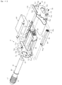
図19〜図21に示すように、冷却装置9は、各構成部材を支持する支持部材として、第1支持部材である背面フレーム71と、第2支持部材である正面内側フレーム72と、第3支持部材である正面外側フレーム73とを有する。背面フレーム71は、ヒートシンク30に対して背面側に配置されるフレームであり、正面内側フレーム72と正面外側フレーム73は、ヒートシンク30に対して正面側に配置されるフレームである。また、正面外側フレーム73は、正面内側フレーム72よりも正面側(外側)に配置される。
19 is a perspective view of the cooling device 9 as viewed from obliquely above, FIG. 20 is a perspective view of the cooling device 9 as viewed from obliquely below, and FIG. 21 is an exploded perspective view of the cooling device 9. In each figure, the near side is the front side, and the far side is the back side.
As shown in FIGS. 19 to 21, the cooling device 9 includes a back frame 71 that is a first support member, a front inner frame 72 that is a second support member, and a third member as support members that support each component. A front outer frame 73 which is a support member. The rear frame 71 is a frame disposed on the back side with respect to the heat sink 30, and the front inner frame 72 and the front outer frame 73 are frames disposed on the front side with respect to the heat sink 30. The front outer frame 73 is disposed on the front side (outer side) of the front inner frame 72.
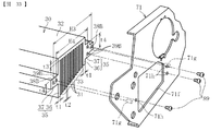
図20に示すように、正面外側フレーム73は、正面内側フレーム72と対向して配置される側面部731と、側面部731の下部から背面側(背面フレーム71側)に延びる底面部732とを有する、略L字型に形成されている。側面部731は、正面内側フレーム72よりも正面側(外側)に配置され、正面内側フレーム72に対して複数のネジ75によって固定される。一方、底面部732は、背面フレーム71に対して複数のネジ76によって固定される。
As shown in FIG. 20, the front outer frame 73 includes a side surface portion 731 disposed to face the front inner frame 72, and a bottom surface portion 732 extending from the lower portion of the side surface portion 731 to the back side (back frame 71 side). It has a substantially L-shape. The side surface portion 731 is disposed on the front side (outer side) of the front inner frame 72 and is fixed to the front inner frame 72 by a plurality of screws 75. On the other hand, the bottom surface portion 732 is fixed to the back frame 71 with a plurality of screws 76.
ヒートシンク30と、搬送ベルト51を張架する駆動ローラ52及び複数の従動ローラ53〜55は、背面フレーム71と正面内側フレーム72とによって支持される。ヒートシンク30は、背面フレーム71と正面内側フレーム72に対して固定され、駆動ローラ52と各従動ローラ53〜55の両端部は、背面フレーム71と正面内側フレーム72に対して回転支持部材としてのベアリングを介して回転可能に取り付けられる。
The heat sink 30, the driving roller 52 that stretches the conveyor belt 51, and the plurality of driven rollers 53 to 55 are supported by the rear frame 71 and the front inner frame 72. The heat sink 30 is fixed to the rear frame 71 and the front inner frame 72, and both ends of the driving roller 52 and the driven rollers 53 to 55 are bearings as rotation support members for the rear frame 71 and the front inner frame 72. It is attached to be rotatable.
図21に示すように、ヒートパイプローラ40は、ヒートシンク30等とは異なり、背面フレーム71と正面外側フレーム73によって支持される。具体的に、背面フレーム71には、ヒートパイプローラ40の円筒部分を挿入して支持するための孔部71aが形成されている。一方、正面外側フレーム73の側面部731には、ヒートパイプローラ40の正面側の端部に設けられた凸部45を挿入し支持するための孔部73aが形成されている。また、これらの孔部71a,73aに挿入されるヒートパイプローラ40の円筒部分及び凸部45は、回転支持部材としてのベアリング46,47(図19参照)を介して回転可能に支持される。
As shown in FIG. 21, the heat pipe roller 40 is supported by a rear frame 71 and a front outer frame 73, unlike the heat sink 30 and the like. Specifically, the back frame 71 is formed with a hole 71 a for inserting and supporting the cylindrical portion of the heat pipe roller 40. On the other hand, the side surface portion 731 of the front outer frame 73 is formed with a hole portion 73 a for inserting and supporting the convex portion 45 provided at the front end portion of the heat pipe roller 40. Moreover, the cylindrical part and the convex part 45 of the heat pipe roller 40 inserted in these hole parts 71a and 73a are rotatably supported through bearings 46 and 47 (refer FIG. 19) as a rotation support member.
さらに、ヒートパイプローラ40の他に、テンションローラ56、(主搬送路26に対して下方に配置される)上流側搬送ローラ64、(主搬送路26に対して下方に配置される)搬送ガイド66、搬送ユニット60も、背面フレーム71と正面外側フレーム73によって支持される(図21参照)。この搬送ユニット60は、図2に示す2つのベルト対向ローラ61,62と、主搬送路26に対して上方に配置される上流側搬送ローラ63と、主搬送路26に対して上方に配置される搬送ガイド65a〜65cを一体のユニットとして構成したものである。
Further, in addition to the heat pipe roller 40, a tension roller 56, an upstream side conveyance roller 64 (located below the main conveyance path 26), and a conveyance guide (located below the main conveyance path 26) 66, the transport unit 60 is also supported by the rear frame 71 and the front outer frame 73 (see FIG. 21). The transport unit 60 is disposed above the two belt facing rollers 61 and 62 shown in FIG. 2, the upstream transport roller 63 disposed above the main transport path 26, and the main transport path 26. The transport guides 65a to 65c are configured as an integral unit.
背面フレーム71と正面外側フレーム73の側面部731には、それぞれ、搬送ユニット60を支持するための支軸71b,73bと、上流側搬送ローラ64の両端部を挿入して支持するための孔部71c,73cと、搬送ガイド66の両端部を固定するネジ77を挿通させる挿通孔71d,73dとが設けられている。
Holes for inserting and supporting the support shafts 71b and 73b for supporting the transport unit 60 and both ends of the upstream transport roller 64 are provided in the side surface portion 731 of the back frame 71 and the front outer frame 73, respectively. 71c, 73c and insertion holes 71d, 73d for inserting screws 77 for fixing both ends of the conveyance guide 66 are provided.
テンションローラ56は、これをバネ57と一緒に保持する保持枠体59が背面フレーム71と正面外側フレーム73の側面部731とに取り付けられることで支持される。具体的には、保持枠体59の背面側と正面側の各端部に、背面フレーム71に設けられた支持突起71eと正面外側フレーム73の側面部731に固定される取付部材74に設けられた支持突起74aとが挿入される複数の挿入孔59aが形成されている。保持枠体59の背面側の挿入孔59aに背面フレーム71の支持突起71eが挿入され、保持枠体59の正面側の挿入孔59aに取付部材74の支持突起74aが挿入された状態で、取付部材74が正面外側フレーム73に固定されることで、テンションローラ56が背面フレーム71と正面外側フレーム73とによって支持される。
The tension roller 56 is supported by attaching a holding frame 59 that holds the tension roller 56 together with the spring 57 to the rear frame 71 and the side surface portion 731 of the front outer frame 73. Specifically, it is provided at each of the rear and front end portions of the holding frame body 59 on a support protrusion 71e provided on the rear frame 71 and an attachment member 74 fixed to the side surface portion 731 of the front outer frame 73. A plurality of insertion holes 59a into which the support protrusions 74a are inserted are formed. When the support projection 71e of the back frame 71 is inserted into the insertion hole 59a on the back side of the holding frame 59, and the support projection 74a of the mounting member 74 is inserted into the insertion hole 59a on the front side of the holding frame 59, the attachment By fixing the member 74 to the front outer frame 73, the tension roller 56 is supported by the rear frame 71 and the front outer frame 73.
また、背面フレーム71、正面内側フレーム72及び正面外側フレーム73には、ヒートシンク30の放熱部33に対向する位置に、放熱部33へ空気を流入又は放熱部33から空気を流出させるための通気孔71f,72f,73fが形成されている。これらの通気孔71f,72f,73fは、放熱部33の外郭形状に対応して略台形に形成されている。
The rear frame 71, the front inner frame 72, and the front outer frame 73 are vent holes for allowing air to flow into or out of the heat radiating portion 33 at positions facing the heat radiating portion 33 of the heat sink 30. 71f, 72f, and 73f are formed. These vent holes 71f, 72f, 73f are formed in a substantially trapezoidal shape corresponding to the outer shape of the heat radiating portion 33.
また、図19に示すように、正面外側フレーム73の側面部731の正面側(外側)には、駆動ローラ52の駆動力を上流側搬送ローラ64に伝達する駆動力伝達部材としてのタイミングベルト84と複数のプーリ85〜88が配置されている。複数のプーリ85〜88のうち、2つのプーリ85,87は駆動ローラ52と上流側搬送ローラ64の正面側の端部に設けられ、残りの2つのプーリ86,88は正面外側フレーム73の側面部731に回転可能に設けられている。タイミングベルト84は、各プーリ85〜88によって張架されている。また、タイミングベルト84は、正面内側フレーム72と正面外側フレーム73に形成された各通気孔72f,73fとは重ならないように配置されている。すなわち、タイミングベルト84は、第1ファン80Aからヒートシンク30へ気流を妨げないように気流経路に侵入しないように配置されている。
Further, as shown in FIG. 19, on the front side (outside) of the side surface portion 731 of the front outer frame 73, a timing belt 84 as a driving force transmission member that transmits the driving force of the driving roller 52 to the upstream conveying roller 64. And a plurality of pulleys 85 to 88 are arranged. Of the plurality of pulleys 85 to 88, the two pulleys 85 and 87 are provided at the front end portions of the driving roller 52 and the upstream conveying roller 64, and the remaining two pulleys 86 and 88 are the side surfaces of the front outer frame 73. The part 731 is rotatably provided. The timing belt 84 is stretched around the pulleys 85 to 88. Further, the timing belt 84 is disposed so as not to overlap the air holes 72 f and 73 f formed in the front inner frame 72 and the front outer frame 73. That is, the timing belt 84 is arranged so as not to enter the air flow path so as not to block the air flow from the first fan 80A to the heat sink 30.
駆動ローラ52が回転駆動すると、各プーリ85〜88及びタイミングベルト84を介して駆動力が上流側搬送ローラ64に伝達される。このように、駆動ローラ52の駆動力を上流側搬送ローラ64に伝達することで、これらのローラ52,64を駆動させる駆動源を別個に設ける必要がなくなり、装置の小型化及び低コスト化を図れる。
When the driving roller 52 is rotationally driven, the driving force is transmitted to the upstream conveying roller 64 via the pulleys 85 to 88 and the timing belt 84. In this way, by transmitting the driving force of the driving roller 52 to the upstream conveying roller 64, it is not necessary to separately provide a driving source for driving these rollers 52 and 64, thereby reducing the size and cost of the apparatus. I can plan.
ところで、駆動ローラ52が回転駆動することによる搬送ベルト51の搬送速度(表面移動速度)は上流側搬送ローラ64の搬送速度(表面移動速度)よりも速くなるように設定されることが望ましい。これは、反対に、搬送ベルト51の搬送速度が上流側搬送ローラ64の搬送速度よりも遅いと、上流側搬送ローラ64から搬送ベルト51へ記録材Pが搬送される際に記録材Pに座屈(波打つような撓み)が発生して、記録材Pと搬送ベルト51との接触面積が減少し、ヒートシンク30による冷却効果が低下する可能性があるからである。
By the way, it is desirable that the conveyance speed (surface movement speed) of the conveyance belt 51 by the drive roller 52 being rotationally driven is set to be faster than the conveyance speed (surface movement speed) of the upstream-side conveyance roller 64. On the contrary, if the conveying speed of the conveying belt 51 is slower than the conveying speed of the upstream conveying roller 64, the recording material P sits on the recording material P when the recording material P is conveyed from the upstream conveying roller 64 to the conveying belt 51. This is because bending (waved bending) occurs, the contact area between the recording material P and the conveyance belt 51 is reduced, and the cooling effect by the heat sink 30 may be reduced.
搬送ベルト51の搬送速度は、少なくとも駆動ローラ52の直径と、搬送ベルト51の厚みと、駆動ローラ52の回転数によって決定される。また、上流側搬送ローラ64の搬送速度は、少なくとも上流側搬送ローラ64の直径と、その回転数によって決定される。また、上流側搬送ローラ64の回転数は、駆動ローラ52の回転数と、駆動ローラ52と上流側搬送ローラ64に設けられた各プーリ85,87の歯数の比によって決まる。従って、これらの条件を適宜決定することで、搬送ベルト51の搬送速度を上流側搬送ローラ64の搬送速度よりも速くすることが可能である。
The conveying speed of the conveying belt 51 is determined at least by the diameter of the driving roller 52, the thickness of the conveying belt 51, and the rotational speed of the driving roller 52. Further, the transport speed of the upstream transport roller 64 is determined at least by the diameter of the upstream transport roller 64 and its rotational speed. Further, the rotation speed of the upstream transport roller 64 is determined by the rotation speed of the drive roller 52 and the ratio of the number of teeth of the pulleys 85 and 87 provided on the drive roller 52 and the upstream transport roller 64. Therefore, by appropriately determining these conditions, the conveyance speed of the conveyance belt 51 can be made faster than the conveyance speed of the upstream conveyance roller 64.
例えば、駆動ローラ52の直径と搬送ベルト51の厚みの合算値と、上流側搬送ローラ64の直径が同じである場合、駆動ローラ52と上流側搬送ローラ64に設けられたプーリ85,87の歯数の比(減速比)を1よりも大きくすればよい。また、これらのプーリ85,87の歯数の比(減速比)が1である場合は、駆動ローラ52の直径と搬送ベルト51の厚みの合算値を上流側搬送ローラ64の直径よりも大きくすればよい。また、駆動ローラ52の直径と搬送ベルト51の厚みの合算値が上流側搬送ローラ64の直径よりも小さい場合は、上流側搬送ローラ64の搬送速度が搬送ベルト51の搬送速度よりも遅くなるように、駆動ローラ52に設けられたプーリ85の歯数よりも上流側搬送ローラ64に設けられたプーリ87の歯数を多くすればよい。
For example, when the sum of the diameter of the driving roller 52 and the thickness of the conveying belt 51 and the diameter of the upstream conveying roller 64 are the same, the teeth of the pulleys 85 and 87 provided on the driving roller 52 and the upstream conveying roller 64 are the same. The ratio of the numbers (reduction ratio) may be larger than 1. When the ratio of the number of teeth of the pulleys 85 and 87 (reduction ratio) is 1, the sum of the diameter of the driving roller 52 and the thickness of the conveying belt 51 is made larger than the diameter of the upstream conveying roller 64. That's fine. When the sum of the diameter of the driving roller 52 and the thickness of the transport belt 51 is smaller than the diameter of the upstream transport roller 64, the transport speed of the upstream transport roller 64 is slower than the transport speed of the transport belt 51. In addition, the number of teeth of the pulley 87 provided on the upstream-side transport roller 64 may be made larger than the number of teeth of the pulley 85 provided on the drive roller 52.
図22は、冷却装置9が画像形成装置本体内に収容された状態における各フレーム71〜73の配置を示す図である。
図22に示すように、冷却装置9を画像形成装置本体内に収容した状態では、各フレーム71〜73の下方近傍に上記レバー90の支軸91が配置される。このため、各フレーム71〜73におけるレバー90の支軸91と対向する下部は、ヒートシンク30の各フィン31の先端部31aや搬送ベルト51に対向してこれらと同様に斜めに配置されている。これにより、各フレーム71〜73とレバー90の支軸91との干渉を回避して小型化を図れるようになる。また、各フレーム71〜73の下部を斜めに配置することで、再供給路28の上方へ膨らむ部分(傾斜部280)との干渉も回避できる。
FIG. 22 is a diagram illustrating the arrangement of the frames 71 to 73 in a state where the cooling device 9 is accommodated in the image forming apparatus main body.
As shown in FIG. 22, in the state where the cooling device 9 is housed in the image forming apparatus main body, the support shaft 91 of the lever 90 is disposed in the vicinity of the lower side of each of the frames 71 to 73. For this reason, the lower portions of the frames 71 to 73 facing the support shaft 91 of the lever 90 are disposed obliquely in the same manner as those facing the tip portions 31a of the fins 31 and the conveyor belt 51 of the heat sink 30. Accordingly, it is possible to reduce the size by avoiding interference between the frames 71 to 73 and the support shaft 91 of the lever 90. In addition, by arranging the lower portions of the frames 71 to 73 obliquely, it is possible to avoid interference with a portion (inclined portion 280) that swells upward in the resupply path 28.
続いて、冷却装置9の組付け方法について説明する。
Next, a method for assembling the cooling device 9 will be described.
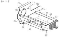
まず、図23に示すように、背面フレーム71と正面内側フレーム72に対して、ヒートシンク30と、搬送ベルト51を張架する駆動ローラ52及び各従動ローラ53〜55を組み付けた状態にする。
First, as shown in FIG. 23, the heat sink 30, the driving roller 52 that stretches the conveyor belt 51, and the driven rollers 53 to 55 are assembled to the rear frame 71 and the front inner frame 72.
次に、図24に示すように、搬送ベルト51の装着を行う。本実施形態では、正面内側フレーム72の外周長M1が搬送ベルト51の内周長M2よりも短く設定されているため、搬送ベルト51を、正面側から正面内側フレーム72の外周側を通して駆動ローラ52及び各従動ローラ53〜55の周囲に装着することができる。
Next, as shown in FIG. 24, the conveyor belt 51 is attached. In the present embodiment, since the outer peripheral length M1 of the front inner frame 72 is set shorter than the inner peripheral length M2 of the conveyor belt 51, the driving roller 52 passes through the outer peripheral side of the front inner frame 72 from the front side. And can be mounted around each driven roller 53-55.
続いて、図25に示すように、搬送ユニット60と上流側搬送ローラ64と搬送ガイド66とを背面フレーム71と正面外側フレーム73に対して組み付けると共に、正面外側フレーム73を背面フレーム71と正面内側フレーム72に対して固定する。具体的には、まず、正面外側フレーム73を背面フレーム71と正面内側フレーム72に対してネジ75,76で固定する(図20参照)。次いで、搬送ユニット60を背面フレーム71と正面外側フレーム73とに設けられた各支軸71b,73bに取り付け、上流側搬送ローラ64の両端部をベアリングを介して背面フレーム71と正面外側フレーム73とに設けられた各孔部71c,73cに挿入する。そして、背面フレーム71と正面外側フレーム73とに設けられた各挿通孔71d,73dにネジ77を挿通し、このネジ77によって搬送ガイド66を背面フレーム71と正面外側フレーム73とに固定する。これにより、背面フレーム71と正面外側フレーム73に対する搬送ユニット60、上流側搬送ローラ64及び搬送ガイド66の組付けと、背面フレーム71と正面内側フレーム72に対する正面外側フレーム73の固定とが完了する。
Subsequently, as shown in FIG. 25, the transport unit 60, the upstream transport roller 64, and the transport guide 66 are assembled to the rear frame 71 and the front outer frame 73, and the front outer frame 73 is connected to the rear frame 71 and the front inner frame. Fix to frame 72. Specifically, first, the front outer frame 73 is fixed to the rear frame 71 and the front inner frame 72 with screws 75 and 76 (see FIG. 20). Next, the transport unit 60 is attached to the respective support shafts 71b and 73b provided on the rear frame 71 and the front outer frame 73, and both ends of the upstream transport roller 64 are connected to the rear frame 71 and the front outer frame 73 via bearings. It inserts in each hole part 71c, 73c provided. Then, screws 77 are inserted through the insertion holes 71 d and 73 d provided in the rear frame 71 and the front outer frame 73, and the conveyance guide 66 is fixed to the rear frame 71 and the front outer frame 73 by the screws 77. Thereby, the assembly of the transport unit 60, the upstream transport roller 64, and the transport guide 66 to the rear frame 71 and the front outer frame 73 and the fixing of the front outer frame 73 to the rear frame 71 and the front inner frame 72 are completed.
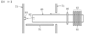
その後、図26に示すように、互いに固定された背面フレーム71と正面外側フレーム73に対してヒートパイプローラ40の組付けを行う。本実施形態では、背面フレーム71に設けられた孔部71aがヒートパイプローラ40の円筒部分の外径D2より大きい径D1(D1>D2)で形成されているため、この孔部71aを通してヒートパイプローラ40の組付けを行うことができる。具体的には、ヒートパイプローラ40の凸部45が設けられた端部を先端にして、ヒートパイプローラ40を背面フレーム71の背面側から背面フレーム71の孔部71aに挿入し、搬送ベルト51上を通過させて、正面外側フレーム73の孔部73aに凸部45を挿入する。
Thereafter, as shown in FIG. 26, the heat pipe roller 40 is assembled to the back frame 71 and the front outer frame 73 fixed to each other. In this embodiment, since the hole 71a provided in the back frame 71 is formed with a diameter D1 (D1> D2) larger than the outer diameter D2 of the cylindrical portion of the heat pipe roller 40, the heat pipe is passed through the hole 71a. The roller 40 can be assembled. Specifically, the heat pipe roller 40 is inserted into the hole 71a of the back frame 71 from the back side of the back frame 71 with the end of the heat pipe roller 40 provided with the convex portion 45 as the tip, and the conveyor belt 51 The projection 45 is inserted into the hole 73 a of the front outer frame 73 through the top.
ヒートパイプローラ40の凸部45が正面外側フレーム73の孔部73aに挿入されると、予めヒートパイプローラ40に装着された放熱部43側のベアリング46が背面フレーム71の孔部71aの縁部に設けられた位置決め部71i(図27参照)に当接する。これにより、ヒートパイプローラ40の挿入方向の位置決めがなされる。そして、正面外側フレーム73の正面側(外側)から凸部45にベアリング47を装着する。さらに、正面外側フレーム73の正面側(外側)から凸部45に抜け止め部材48(図27参照)を装着し、ヒートパイプローラ40が背面側へ離脱しないようにする。
When the convex portion 45 of the heat pipe roller 40 is inserted into the hole 73 a of the front outer frame 73, the bearing 46 on the side of the heat radiating portion 43 mounted on the heat pipe roller 40 in advance is the edge of the hole 71 a of the back frame 71. It abuts on a positioning portion 71i (see FIG. 27) provided on the surface. Thereby, positioning of the insertion direction of the heat pipe roller 40 is made. Then, the bearing 47 is mounted on the convex portion 45 from the front side (outer side) of the front outer frame 73. Further, a retaining member 48 (see FIG. 27) is attached to the convex portion 45 from the front side (outer side) of the front outer frame 73 so that the heat pipe roller 40 is not detached to the rear side.
その後、図28に示すように、テンションローラ56の組付けを行う。具体的には、まず、テンションローラ56を保持する保持枠体59の背面側の端部に形成された挿入孔59aに、背面フレーム71に設けられた支持突起71eを挿入する。次いで、テンションローラ56を搬送ベルト51に押し付けた状態にして、保持枠体59の正面側の端部に形成された挿入孔59aを正面外側フレーム73に形成された挿通孔73eに一致させる。この状態で、正面外側フレーム73の挿通孔73eと保持枠体59の正面側の挿入孔59aに対して取付部材74の支持突起74aを正面側(外側)から挿入し、取付部材74を正面外側フレーム73に対してネジ78で固定する。これにより、テンションローラ56が背面フレーム71と正面外側フレーム73との間で支持される。
Thereafter, as shown in FIG. 28, the tension roller 56 is assembled. Specifically, first, the support protrusion 71e provided on the back frame 71 is inserted into the insertion hole 59a formed at the end on the back side of the holding frame body 59 that holds the tension roller 56. Next, the tension roller 56 is pressed against the conveyor belt 51, and the insertion hole 59 a formed at the front end of the holding frame body 59 is made to coincide with the insertion hole 73 e formed in the front outer frame 73. In this state, the support protrusion 74a of the mounting member 74 is inserted from the front side (outside) into the insertion hole 73e of the front outer frame 73 and the insertion hole 59a on the front side of the holding frame body 59, and the mounting member 74 is moved to the front outer side. The frame 73 is fixed with screws 78. Thereby, the tension roller 56 is supported between the back frame 71 and the front outer frame 73.
最後に、駆動ローラ52と上流側搬送ローラ64の正面側の各端部及び正面外側フレーム73にそれぞれプーリ85〜88を取り付け、これらのプーリ85〜88にタイミングベルト84を掛け渡す(図19参照)。
Finally, pulleys 85 to 88 are attached to the front end portions of the driving roller 52 and the upstream conveying roller 64 and the front outer frame 73, respectively, and the timing belt 84 is passed over these pulleys 85 to 88 (see FIG. 19). ).
上記のように、本実施形態では、背面側に配置される1つの支持部材(背面フレーム71)と、正面側に配置される2つの支持部材(正面内側フレーム72及び正面外側フレーム73)によって、各構成部材を支持するように構成されているので、各構成部材を背面側と正面側の一対の支持部材で支持する場合に比べて、各構成部材の組付け作業が行いやすくなる。すなわち、各構成部材を一対の支持部材で支持する場合は、1つの支持部材に組み付けられる構成部材の数が必然的に多くなり、組付け作業が複雑化する傾向にあるが、構成部材に応じて支持する支持部材を分けることで、1つの支持部材に組み付けられる構成部材の数を減らすことができ、組付け作業を容易に行えるようになる。
As described above, in the present embodiment, one support member (back frame 71) disposed on the back side and two support members (front inner frame 72 and front outer frame 73) disposed on the front side, Since each component member is configured to be supported, it is easier to assemble each component member than when each component member is supported by a pair of support members on the back side and the front side. That is, when each component member is supported by a pair of support members, the number of component members assembled to one support member inevitably increases, and the assembly work tends to be complicated. By separating the supporting members to be supported in this manner, the number of constituent members assembled to one supporting member can be reduced, and the assembling work can be easily performed.
また、構成部材に応じて支持する支持部材を分けることで、一部の構成部材の組み付けを完了した後で、残りの構成部材の組み付けを行うことができる。これにより、組付け作業を確実に行うことができるようになり、組付け精度も向上する。特に、本実施形態では、比較的重量のある構成部材であるヒートシンク30とヒートパイプローラ40を別々の支持部材(正面内側フレーム72と正面外側フレーム73)に組み付けるようにしているので、ヒートシンク30の組付けを完了した後に、ヒートパイプローラ40の組付けを行うことができ、組付け作業性が向上する。
Further, by separating the supporting members to be supported according to the constituent members, the remaining constituent members can be assembled after the assembly of some of the constituent members is completed. As a result, the assembling work can be performed reliably, and the assembling accuracy is improved. In particular, in the present embodiment, the heat sink 30 and the heat pipe roller 40 which are relatively heavy components are assembled to separate support members (the front inner frame 72 and the front outer frame 73). After completing the assembly, the heat pipe roller 40 can be assembled, and the assembly workability is improved.
また、ヒートパイプローラ40を支持する正面外側フレーム73は、ヒートシンク30や駆動ローラ52及び従動ローラ53〜53を支持する正面内側フレーム72に対して固定されるので、ヒートパイプローラ40、ヒートシンク30、駆動ローラ52及び従動ローラ53〜55の相互間の位置決め精度を確保することができる。しかも、正面外側フレーム73は正面内側フレーム72に対して正面側(外側)から固定できるので、固定作業が行いやすい。
The front outer frame 73 that supports the heat pipe roller 40 is fixed to the front inner frame 72 that supports the heat sink 30, the drive roller 52, and the driven rollers 53 to 53, so that the heat pipe roller 40, the heat sink 30, The positioning accuracy between the driving roller 52 and the driven rollers 53 to 55 can be ensured. In addition, since the front outer frame 73 can be fixed to the front inner frame 72 from the front side (outer side), it is easy to perform the fixing operation.
また、本実施形態では、搬送ベルト51の装着を、背面フレーム71と正面内側フレーム72に対するヒートシンク30や駆動ローラ52及び各従動ローラ53〜55の組付けが完了した後で行うことができるので、組付け作業性が向上する。すなわち、先に搬送ベルト51を各ローラ52〜55の周囲に掛け回し、さらに搬送ベルト51の内側にヒートシンク30を配置した状態で、背面フレーム71と正面内側フレーム72に対する組付けを行わなくてもよいので、組付け作業が行いやすくなる。なお、駆動ローラ52の表面がゴムなどの摩擦係数の高い部材で被覆されている場合は、駆動ローラ52に対して搬送ベルト51が滑りにくいため、各ローラ52〜55のうち、駆動ローラ52だけ組み付けない状態で搬送ベルト51を装着して、その後で駆動ローラ52を組み付けてもよい。
Further, in the present embodiment, the conveyance belt 51 can be attached after the heat sink 30, the driving roller 52, and the driven rollers 53 to 55 are assembled to the back frame 71 and the front inner frame 72. Assembly workability is improved. That is, it is not necessary to assemble the rear frame 71 and the front inner frame 72 in a state where the conveyor belt 51 is first wound around the rollers 52 to 55 and the heat sink 30 is disposed inside the conveyor belt 51. Since it is good, the assembly work becomes easier. In addition, when the surface of the driving roller 52 is covered with a member having a high friction coefficient such as rubber, the conveying belt 51 is difficult to slip with respect to the driving roller 52, so that only the driving roller 52 among the rollers 52 to 55 is included. The conveying belt 51 may be attached in a state where it is not assembled, and then the driving roller 52 may be assembled.
なお、冷却装置9を分解する場合は、上記組付け時の手順とは逆の手順で各構成部材の取り外しを行えばよい。その場合、搬送ベルト51は、組付け時とは反対に正面側にスライド移動させることで取り外すことができる。また、本実施形態では、各従動ローラ53〜55が正面内側フレーム72の外郭よりも外側に多少突出するように配置されているため(図22中の突出量E参照)、各従動ローラ53〜55に沿って搬送ベルト51をスライド移動させることで、搬送ベルト51が正面内側フレーム72に対して引っ掛かりにくく取り外しやすい。
In addition, when disassembling the cooling device 9, each constituent member may be removed by a procedure reverse to the procedure at the time of assembly. In that case, the conveyor belt 51 can be removed by sliding it to the front side as opposed to during assembly. Further, in the present embodiment, the driven rollers 53 to 55 are arranged so as to slightly protrude outward from the outline of the front inner frame 72 (see the protruding amount E in FIG. 22). By causing the conveyor belt 51 to slide along 55, the conveyor belt 51 is not easily caught on the front inner frame 72 and can be easily removed.
また、本実施形態のように、テンションローラ56を正面内側フレーム72ではなく正面外側フレーム73に組み付ける構成とすることで、正面内側フレーム72にテンションローラ56を組み付ける部分を設ける必要がないので、正面内側フレーム72をコンパクトに構成することができる。これにより、正面内側フレーム72の外周長M1を搬送ベルト51の内周長M2よりも短くするといった設計が容易になり、ヒートシンク30と各ローラ52〜55の組付け後に搬送ベルト51の装着を行える構成を実現しやすくなる。
In addition, since the tension roller 56 is assembled not to the front inner frame 72 but to the front outer frame 73 as in this embodiment, there is no need to provide a portion for assembling the tension roller 56 to the front inner frame 72. The inner frame 72 can be configured compactly. This facilitates the design such that the outer peripheral length M1 of the front inner frame 72 is shorter than the inner peripheral length M2 of the transport belt 51, and the transport belt 51 can be mounted after the heat sink 30 and the rollers 52 to 55 are assembled. It becomes easy to realize the configuration.
また、ヒートパイプローラ40を組み付けする際、挿入方向の先端部にある凸部45がヒートパイプローラ40の円筒部分の外周面よりも外側に突出していないので、凸部45が周囲の部材と干渉するのを回避することができる。例えば、図29に示す例のように、ヒートパイプローラ40の先端部側を支持する支持部としてヒートパイプローラ40の円筒部分の外周面にベアリング49を装着している場合は、ヒートパイプローラ40を挿入する際にベアリング49が搬送ベルト51に接触してこれを傷付ける虞がある。これに対し、本実施形態では、支持部としての凸部45がヒートパイプローラ40の円筒部分の外周面よりも外側(組付け時の移動方向と交差する方向)に突出していないので、周囲の部材との干渉を回避することができる。これにより、干渉による部材の損傷を防止できると共に、組付け作業もスムーズに行えるようになる。
Further, when the heat pipe roller 40 is assembled, the convex portion 45 at the distal end in the insertion direction does not protrude outward from the outer peripheral surface of the cylindrical portion of the heat pipe roller 40, so the convex portion 45 interferes with surrounding members. Can be avoided. For example, as in the example shown in FIG. 29, when the bearing 49 is mounted on the outer peripheral surface of the cylindrical portion of the heat pipe roller 40 as a support portion that supports the tip end side of the heat pipe roller 40, the heat pipe roller 40 When inserting the bearing 49, the bearing 49 may come into contact with the conveyor belt 51 to damage it. On the other hand, in the present embodiment, the convex portion 45 as the support portion does not protrude outward (in the direction intersecting the moving direction at the time of assembly) from the outer peripheral surface of the cylindrical portion of the heat pipe roller 40. Interference with the member can be avoided. As a result, damage to the member due to interference can be prevented, and the assembling work can be performed smoothly.
なお、本実施形態では、ヒートパイプローラ40の先端部に凸部45を設け、これを受ける正面外側フレーム73の部分に孔部73aを設けているが、この構成に限らない。例えば、図30に示す例のように、ヒートパイプローラ40の先端部に孔部(凹部)92を設け、正面外側フレーム73に前記孔部(凹部)92に挿入される凸部93を設けてもよい。この場合も、周囲の部材との干渉を回避しつつヒートパイプローラ40の組付けを行うことができる。
In the present embodiment, the protrusion 45 is provided at the tip of the heat pipe roller 40, and the hole 73a is provided in the portion of the front outer frame 73 that receives the protrusion 45, but this is not restrictive. For example, as shown in the example shown in FIG. 30, a hole (recess) 92 is provided at the tip of the heat pipe roller 40, and a protrusion 93 inserted into the hole (recess) 92 is provided on the front outer frame 73. Also good. Also in this case, the heat pipe roller 40 can be assembled while avoiding interference with surrounding members.
以上のように、本実施形態に係る構成によれば、冷却装置9の組付け作業性が向上し、組付けを確実に行うことができるようになるので、各構成部材の組付け誤差や歪みの発生が少なくなる。これにより、搬送ベルト51に対するヒートシンク30やヒートパイプローラ40の密着性を良好に確保することができるようになり、安定した冷却機能を発揮することができる。
As described above, according to the configuration according to the present embodiment, the assembling workability of the cooling device 9 is improved and the assembling can be surely performed. The occurrence of is reduced. Thereby, the adhesiveness of the heat sink 30 and the heat pipe roller 40 with respect to the conveyance belt 51 can be ensured satisfactorily, and a stable cooling function can be exhibited.
続いて、各フレーム71〜73に対するヒートシンク30の組付け構造について説明する。
Subsequently, an assembly structure of the heat sink 30 to each of the frames 71 to 73 will be described.
まず、図31に基づいて、正面側の組付け構造について説明する。
ヒートシンク30の一対の突出部37の正面側の端面には、正面内側フレーム72と正面外側フレーム73の両方を位置決めする位置決め部としての位置決め突起38Aが設けられている。位置決め突起38Aは、丸棒状に形成された金属製のピンであり、突出部37に設けられた孔部に圧入されて取り付けられる。また、各突出部37の正面側の端面には、正面内側フレーム72に対して固定される固定部としてのネジ止め孔39Aが設けられている。なお、搬送方向の下流側(図31の奥側)に配置される突出部37には2つのネジ止め孔39Aが上下方向に並んで設けられ、搬送方向の上流側(図31の手前側)に配置される突出部37にはネジ止め孔39Aが1つ設けられているが、ネジ止め孔39Aの個数や配置は適宜変更可能である。
First, the assembly structure on the front side will be described with reference to FIG.
Positioning projections 38 </ b> A as positioning portions for positioning both the front inner frame 72 and the front outer frame 73 are provided on the front end surfaces of the pair of protrusions 37 of the heat sink 30. The positioning protrusion 38A is a metal pin formed in a round bar shape, and is pressed into a hole provided in the protruding portion 37 and attached. Further, a screwing hole 39 </ b> A as a fixing portion fixed to the front inner frame 72 is provided on the front end face of each protruding portion 37. In addition, two screwing holes 39A are provided side by side in the up-down direction in the protruding portion 37 arranged on the downstream side in the transport direction (the back side in FIG. 31), and upstream in the transport direction (the near side in FIG. 31). One screwing hole 39A is provided in the projecting portion 37 arranged in the above, but the number and arrangement of the screwing holes 39A can be appropriately changed.
一方、正面内側フレーム72と正面外側フレーム73には、ヒートシンク30の位置決め突起38Aと嵌合する位置決め部としての位置決め孔72g,73gが形成されている。さらに、正面内側フレーム72と正面外側フレーム73には、ヒートシンク30のネジ止め孔39Aに締結されるねじ89を挿通させる挿通孔72h,73hが形成されている。なお、正面外側フレーム73に形成される位置決め孔73gのうち、搬送方向の上流側(図31の手前側)の位置決め孔73gと、両側の挿通孔73hは、通気孔73fと一体的に形成されている。
On the other hand, in the front inner frame 72 and the front outer frame 73, positioning holes 72g and 73g are formed as positioning portions that fit into the positioning protrusions 38A of the heat sink 30. Further, the front inner frame 72 and the front outer frame 73 are formed with insertion holes 72h and 73h through which screws 89 fastened to the screw fixing holes 39A of the heat sink 30 are inserted. Of the positioning holes 73g formed in the front outer frame 73, the positioning hole 73g on the upstream side in the transport direction (front side in FIG. 31) and the insertion holes 73h on both sides are formed integrally with the vent hole 73f. ing.
ヒートシンク30を正面内側フレーム72と正面外側フレーム73に組み付けるには、まず、ヒートシンク30の各位置決め突起38Aを正面内側フレーム72の各位置決め孔72gに挿通させる。次いで、各位置決め突起38Aをさらに正面外側フレーム73の各位置決め孔73gに挿通させる。これにより、位置決め突起38Aが各フレーム72,73の各位置決め孔72g,73gと嵌合し、ヒートシンク30と各フレーム72,73の位置決めがなされる。そして、正面側(外側)からネジ89を、正面外側フレーム73の挿通孔73h、正面内側フレーム72の挿通孔72hを通して、ヒートシンク30のネジ止め孔39Aに締結する。これにより、ネジ89によってヒートシンク30と正面内側フレーム72とが固定される。なお、このネジ89の締結によって、ヒートシンク30と正面内側フレーム72とは固定されるが、ヒートシンク30と正面外側フレーム73とは固定されない(図32に示すように、ネジ89が締結された状態で、ネジ89の頭部は正面外側フレーム73の挿通孔73hに対しては挿通された状態にある。)。上記のように、正面外側フレーム73は、正面内側フレーム72に対してネジ75によって固定されることで(図20参照)、正面内側フレーム72を介してヒートシンク30と固定される。
In order to assemble the heat sink 30 to the front inner frame 72 and the front outer frame 73, first, the positioning protrusions 38A of the heat sink 30 are inserted through the positioning holes 72g of the front inner frame 72. Next, each positioning projection 38 </ b> A is further inserted into each positioning hole 73 g of the front outer frame 73. Thereby, the positioning protrusion 38A is fitted into the positioning holes 72g and 73g of the frames 72 and 73, and the heat sink 30 and the frames 72 and 73 are positioned. Then, the screw 89 is fastened from the front side (outside) to the screw fixing hole 39A of the heat sink 30 through the insertion hole 73h of the front outer frame 73 and the insertion hole 72h of the front inner frame 72. Thereby, the heat sink 30 and the front inner frame 72 are fixed by the screw 89. The heat sink 30 and the front inner frame 72 are fixed by fastening the screws 89, but the heat sink 30 and the front outer frame 73 are not fixed (as shown in FIG. 32, the screws 89 are fastened). The head of the screw 89 is inserted into the insertion hole 73h of the front outer frame 73. As described above, the front outer frame 73 is fixed to the heat sink 30 via the front inner frame 72 by being fixed to the front inner frame 72 with the screws 75 (see FIG. 20).
次に、図33に基づいて、背面側の組付け構造について説明する。
ヒートシンク30の一対の突出部37の背面側の端面には、背面フレーム71を位置決めする位置決め部としての位置決め孔38Bが設けられている。さらに、各突出部37の背面側の端面には、背面フレーム71に対して固定される固定部としてのネジ止め孔39Bが形成されている。なお、上記正面側に設けられるネジ止め孔39Aと同様、背面側に設けられるネジ止め孔39Bの個数や配置は適宜変更可能である。
Next, the assembly structure on the back side will be described with reference to FIG.
Positioning holes 38 </ b> B serving as positioning portions for positioning the back frame 71 are provided on the back end surfaces of the pair of protrusions 37 of the heat sink 30. Further, a screwing hole 39 </ b> B as a fixing portion that is fixed to the rear frame 71 is formed on the rear end face of each protruding portion 37. Note that the number and arrangement of the screwing holes 39B provided on the back side can be changed as appropriate, similarly to the screwing holes 39A provided on the front side.
一方、背面フレーム71には、ヒートシンク30の位置決め孔38Bと嵌合する位置決め部としての位置決め突起71gが形成されている。さらに、背面フレーム71には、ヒートシンク30のネジ止め孔39Bに締結されるねじ89を挿通させる挿通孔71hが形成されている。
On the other hand, the rear frame 71 is formed with positioning protrusions 71g as positioning portions that fit into the positioning holes 38B of the heat sink 30. Further, the rear frame 71 is formed with an insertion hole 71h through which a screw 89 fastened to the screwing hole 39B of the heat sink 30 is inserted.
ヒートシンク30を背面フレーム71に組み付けるには、まず、背面フレーム71の各位置決め突起71gをヒートシンク30の各位置決め孔38Bに挿通させる。これにより、位置決め突起71gが位置決め孔38Bと嵌合し、ヒートシンク30と背面フレーム71との位置決めがなされる。そして、背面側(外側)からネジ89を、背面フレーム71の挿通孔71hを通して、ヒートシンク30のネジ止め孔39Bに締結する。これにより、ネジ89によってヒートシンク30と背面フレーム71とが固定される。図34に、ヒートシンク30が背面フレーム71に対して組み付けられた状態を示す。
In order to assemble the heat sink 30 to the back frame 71, first, each positioning projection 71g of the back frame 71 is inserted into each positioning hole 38B of the heat sink 30. As a result, the positioning projection 71g is fitted into the positioning hole 38B, and the heat sink 30 and the rear frame 71 are positioned. Then, the screw 89 is fastened from the back side (outside) to the screwing hole 39B of the heat sink 30 through the insertion hole 71h of the back frame 71. Thereby, the heat sink 30 and the back frame 71 are fixed by the screw 89. FIG. 34 shows a state where the heat sink 30 is assembled to the back frame 71.
上記のように、本実施形態では、ヒートシンク30において剛性の高い部分である補強部35(突出部37)にネジ止め孔39A,39Bを形成し、このネジ止め孔39A,39Bにネジ89を締結することで正面内側フレーム72と背面フレーム71に対するヒートシンク30の固定を行うようにしている。すなわち、ヒートシンク30の剛性の高い補強部35(突出部37)を各フレーム71,72に固定するので、ヒートシンク30を各フレーム71,72に固定したときの構造体の剛性が向上し、構造体にひずみが生じたり、ヒートシンク30の姿勢が不安定になったりするのを抑制することができる。これにより、搬送ベルト51に対するヒートシンク30の密着性を良好に確保することができ、所望の冷却性能が得られるようになる。また、搬送ベルト51に対するヒートシンク30の接触不均一も抑制できるので、搬送ベルト51の幅方向の一方への寄り移動も抑制でき、搬送ベルト51の搬送性も良好に得られる。
As described above, in this embodiment, screw holes 39A and 39B are formed in the reinforcing portion 35 (projecting portion 37) which is a highly rigid portion in the heat sink 30, and screws 89 are fastened to the screw holes 39A and 39B. By doing so, the heat sink 30 is fixed to the front inner frame 72 and the rear frame 71. That is, since the high-strength reinforcing portion 35 (projecting portion 37) of the heat sink 30 is fixed to the frames 71 and 72, the rigidity of the structure when the heat sink 30 is fixed to the frames 71 and 72 is improved. It is possible to suppress the occurrence of distortion and the unstable posture of the heat sink 30. Thereby, the adhesiveness of the heat sink 30 with respect to the conveyance belt 51 can be ensured favorably, and a desired cooling performance can be obtained. Moreover, since the contact nonuniformity of the heat sink 30 with respect to the conveyance belt 51 can also be suppressed, the movement of the conveyance belt 51 toward one side in the width direction can also be suppressed, and the conveyance performance of the conveyance belt 51 can be obtained well.
特に、本実施形態では、突出部37が、側壁部36とフィン31と受熱部32のいずれよりも厚く剛性が高いので(図31、図33中、t4>t1、t2、t3)、この突出部37と各フレーム71,72とを固定することで構造体全体の剛性が高くなる。また、本実施形態では、側壁部36をフィン31よりも厚く形成することで側壁部36の剛性を高め(図31、図33中、t1>t2)、側壁部36と突出部37との接続部に応力集中が生じても、側壁部36に撓みや捩れが生じにくくなるようにしている。
In particular, in the present embodiment, the protruding portion 37 is thicker and more rigid than any of the side wall portion 36, the fin 31, and the heat receiving portion 32 (t4> t1, t2, t3 in FIGS. 31 and 33). By fixing the portion 37 and the frames 71 and 72, the rigidity of the entire structure is increased. Further, in the present embodiment, the side wall 36 is formed thicker than the fin 31 to increase the rigidity of the side wall 36 (t1> t2 in FIGS. 31 and 33), and the connection between the side wall 36 and the protrusion 37 is achieved. Even if stress concentration occurs in the portion, the side wall portion 36 is less likely to be bent or twisted.
本実施形態では、正面内側フレーム72と背面フレーム71に対してヒートシンク30の補強部35が直接接触して固定されるが、両部材間にスペーサを介在させたり隙間をあけたりして、直接接触させずに固定してもよい。例えば、スペーサとしてスポンジ等の反発力の小さい弾性部材を用いることで、正面内側フレーム72や背面フレーム71の屈曲を抑制でき、これらのフレーム71,72と突出部37との干渉を回避することができる。
In the present embodiment, the reinforcing portion 35 of the heat sink 30 is directly contacted and fixed to the front inner frame 72 and the rear frame 71, but is in direct contact by interposing a spacer between the two members or providing a gap. You may fix without letting it. For example, by using an elastic member having a small repulsive force such as a sponge as the spacer, the bending of the front inner frame 72 and the rear frame 71 can be suppressed, and interference between the frames 71 and 72 and the protruding portion 37 can be avoided. it can.
また、本実施形態では、各フレーム71,72が補強部35(突出部37)の正面側又は背面側の端面(正面又は背面を臨む端面)に接触して固定されているが、この固定箇所は、補強部35の搬送方向と交差する搬送幅方向端部側であれば、正面側又は背面側の端面以外の面であってもよい。例えば、補強部35(突出部37)の搬送方向の上流側又は下流側を臨む面あるいは上面又は下面に各フレーム71,72を接触させて固定してもよい。
Moreover, in this embodiment, each frame 71 and 72 is fixed in contact with the end surface (end surface facing the front surface or the back surface) of the front side or the back side of the reinforcing portion 35 (projection portion 37). May be a surface other than the end surface on the front side or the back side as long as it is on the end side in the transport width direction intersecting the transport direction of the reinforcing portion 35. For example, the frames 71 and 72 may be fixed in contact with a surface facing the upstream side or the downstream side in the transport direction of the reinforcing portion 35 (projecting portion 37), or an upper surface or a lower surface.
また、本実施形態では、正面内側フレーム72と正面外側フレーム73とが、いずれもヒートシンク30に設けられた位置決め突起38Aによって位置決めされるため、これらのフレーム72,73同士の相対的位置精度が向上する。すなわち、それぞれの位置決め基準が同じであるので、これらのフレーム72,73に組み付けられる各構成部材同士の相対的位置精度も向上する。これにより、ヒートシンク30とヒートパイプローラ40とを互いに接近させて精度良く位置決めすることができるため{これらの両受熱部32,42間の距離(図2中の符号Zで示す距離)を短くすることができるため}、小型化と冷却性能の向上を実現できる。
Further, in this embodiment, since the front inner frame 72 and the front outer frame 73 are both positioned by the positioning protrusions 38A provided on the heat sink 30, the relative positional accuracy between these frames 72 and 73 is improved. To do. That is, since each positioning reference is the same, the relative positional accuracy of the constituent members assembled to these frames 72 and 73 is also improved. Thereby, since the heat sink 30 and the heat pipe roller 40 can be positioned close to each other with high precision, the distance between the heat receiving portions 32 and 42 (the distance indicated by the symbol Z in FIG. 2) is shortened. Therefore, it is possible to reduce the size and improve the cooling performance.
また、本実施形態では、ヒートシンク30に設けられる位置決め部(位置決め突起38A、位置決め孔38B)は、ヒートシンク30に設けられる固定部(ネジ止め孔39A、ネジ止め孔39B)よりも搬送方向に互いに離れた位置に配置されている。すなわち、図31に示す正面側では、位置決め突起38A同士の搬送方向の距離H1がネジ止め孔39A同士の搬送方向の距離H2よりも長く、図32に示す背面側では、位置決め孔38B同士の搬送方向の距離H3もネジ止め孔49B同士の搬送方向の距離H4よりも長い。このように、位置決め部同士が互いに離れた位置に配置されているため、互いに近い位置に配置されている場合よりも位置決め精度が向上する。
In the present embodiment, the positioning portions (positioning protrusions 38A and positioning holes 38B) provided in the heat sink 30 are separated from each other in the transport direction than the fixing portions (screw fixing holes 39A and screw fixing holes 39B) provided in the heat sink 30. It is arranged at the position. That is, on the front side shown in FIG. 31, the distance H1 in the conveyance direction between the positioning protrusions 38A is longer than the distance H2 in the conveyance direction between the screwing holes 39A, and on the back side shown in FIG. The distance H3 in the direction is also longer than the distance H4 in the transport direction between the screw holes 49B. Thus, since the positioning parts are arranged at positions separated from each other, the positioning accuracy is improved as compared with the case where the positioning parts are arranged at positions close to each other.
また、ヒートシンク30に設けられる位置決め部(位置決め突起38A、位置決め孔38B)と固定部(ネジ止め孔39A、ネジ止め孔39B)は、上下方向に並べて配置することもできるが、本実施形態では水平方向(搬送方向)に並べて配置している。これにより、突出部37の特に上下方向のサイズアップを抑制することができる。
Further, the positioning portions (positioning protrusions 38A and positioning holes 38B) and the fixing portions (screw fixing holes 39A and screw fixing holes 39B) provided on the heat sink 30 can be arranged side by side in the vertical direction. They are arranged side by side in the direction (conveyance direction). Thereby, the size increase of the protrusion part 37 especially in an up-down direction can be suppressed.
図35は、ヒートシンク30を固定する部分の構成を示す図である。
図35(a)に示す例は、ヒートシンク30の補強部35である側壁部36を受熱部32よりも厚く構成し(t1>t3)、その側壁部36にネジ止め孔39Aを設けたものである。この場合、厚く構成された側壁部36にネジ止め孔39Aが設けられているので、正面内側フレーム72や背面フレーム71に対してヒートシンク30を固定したときの構造体の剛性が向上する。一方、受熱部32は薄く構成されているので、フィン31への熱伝導性が良く、冷却性能が高くなる。
FIG. 35 is a diagram illustrating a configuration of a portion for fixing the heat sink 30.
In the example shown in FIG. 35 (a), the side wall portion 36 that is the reinforcing portion 35 of the heat sink 30 is configured to be thicker than the heat receiving portion 32 (t1> t3), and the side wall portion 36 is provided with a screw hole 39A. is there. In this case, since the screwing hole 39A is provided in the thick side wall portion 36, the rigidity of the structure when the heat sink 30 is fixed to the front inner frame 72 and the rear frame 71 is improved. On the other hand, since the heat receiving part 32 is configured to be thin, the heat conductivity to the fins 31 is good and the cooling performance is high.
図35(b)に示す例は、同図(a)に示す例とは反対に、受熱部32を側壁部36よりも厚く構成し(t3>t1)、その受熱部32にネジ止め孔39Aを設けたものである。この場合、厚く構成された受熱部32が正面内側フレーム72や背面フレーム71に固定されるため、構造体の剛性が向上する。また、この場合、側壁部36にはネジ止め孔39Aを設けなくてもよいため、側壁部36をフィン31と同じ厚さにすることで(t1=t2)、放熱部として機能させることができる。
In the example shown in FIG. 35 (b), contrary to the example shown in FIG. 35 (a), the heat receiving portion 32 is configured to be thicker than the side wall portion 36 (t3> t1), and the screw receiving hole 39A is formed in the heat receiving portion 32. Is provided. In this case, since the heat receiving portion 32 having a large thickness is fixed to the front inner frame 72 and the rear frame 71, the rigidity of the structure is improved. Further, in this case, the side wall portion 36 does not need to be provided with the screwing hole 39A. Therefore, by making the side wall portion 36 the same thickness as the fin 31 (t1 = t2), it can function as a heat radiating portion. .
図35(c)に示す例は、側壁部36と受熱部32の両方を厚く構成し、それぞれにネジ止め孔39Aを設けたものである。この場合、図35(a)(b)に示す例に比べて、構造体としての剛性が高くなる。
In the example shown in FIG. 35 (c), both the side wall portion 36 and the heat receiving portion 32 are configured to be thick and provided with a screwing hole 39A. In this case, the rigidity as the structure is higher than in the example shown in FIGS.
上記のように、図35(a)に示す例は、同図(b)(c)に示す例に比べて受熱部32を薄くできるため冷却性能が向上する長所がある。しかしながら、図35(a)に示す例のように側壁部36を一様に厚く形成するとコストが高くなったり装置が大型化したりする短所がある。これに対し、上記本実施形態では、側壁部36を一様に厚くするのではなく、部分的に厚くして突出部37を構成し、この突出部37にネジ止め孔39Aを設けている。図31,33に示すように、t4>t1、t3>t2としている。また、図31,33に示す受熱部32の厚さt3は、図35(a)の受熱部32のように薄くしている。さらに、図31,33に示すt3とt1はほぼ同じ厚さであり、t1はt2の約2倍としている。このように構成することで、側壁部36を一様に厚くする例に比べて、低コスト化及び小型化を図ることができるようになる。ただし、本発明に係る冷却装置は、この実施形態に限定されるものではなく、要求される冷却性能や剛性等に応じて図35に示す各例の構成を採用してもよい。
As described above, the example shown in FIG. 35A has an advantage that the cooling performance is improved because the heat receiving portion 32 can be made thinner than the examples shown in FIGS. However, when the side wall portion 36 is formed uniformly thick as in the example shown in FIG. 35A, there are disadvantages that the cost is increased and the apparatus is enlarged. On the other hand, in the present embodiment, the side wall portion 36 is not uniformly thickened, but is partially thickened to form the projecting portion 37, and the screwing hole 39A is provided in the projecting portion 37. As shown in FIGS. 31 and 33, t4> t1 and t3> t2. Moreover, the thickness t3 of the heat receiving part 32 shown in FIGS. 31 and 33 is made thin like the heat receiving part 32 in FIG. Further, t3 and t1 shown in FIGS. 31 and 33 have substantially the same thickness, and t1 is approximately twice t2. With this configuration, it is possible to reduce the cost and size as compared with the example in which the side wall portion 36 is uniformly thickened. However, the cooling device according to the present invention is not limited to this embodiment, and the configuration of each example shown in FIG. 35 may be adopted according to required cooling performance, rigidity, and the like.
図36は、搬送ベルト51の幅方向への寄り止め構造を示す図である。
図36に示すように、搬送ベルト51の幅方向端部の内周面には、搬送ベルト51の幅方向の移動を規制する幅方向移動規制部としての規制凸部51bが周方向全体に渡って設けられている。図36では、搬送ベルト51の一端部側の構成のみ示しているが、反対側の端部にも同様に規制凸部51bが設けられている。このように、搬送ベルト51の幅方向両端部に規制凸部51bが設けられていることで、仮に、搬送ベルト51が幅方向の一方に移動したとしても、一方の規制凸部51bが駆動ローラ52のローラ部52aの一端部側に接触することで、搬送ベルト51の幅方向への移動が規制される。
FIG. 36 is a view showing a structure for preventing the conveyance belt 51 from shifting in the width direction.
As shown in FIG. 36, on the inner peripheral surface of the end portion in the width direction of the conveyor belt 51, a restricting convex portion 51b as a width direction movement restricting portion that restricts the movement of the convey belt 51 in the width direction extends over the entire circumferential direction. Is provided. In FIG. 36, only the configuration on the one end portion side of the conveyor belt 51 is shown, but the restricting convex portion 51b is similarly provided on the opposite end portion. As described above, since the regulation convex portions 51b are provided at both ends in the width direction of the transport belt 51, even if the transport belt 51 moves to one side in the width direction, the one regulation convex portion 51b becomes the driving roller. The movement of the conveyance belt 51 in the width direction is restricted by contacting one end of the roller portion 52a.
規制凸部51bは、搬送ベルト51の本体部と同様に可撓性を有する樹脂又はゴムで構成されている。一方、駆動ローラ52は金属製である。このため、樹脂、又はゴム製の規制凸部51bが直接金属製のローラ部52に接触すると、規制凸部51bの摩耗が激しくなる虞がある。そこで、本実施形態では、規制凸部51bの摩耗を抑制するため、駆動ローラ52のローラ部52の両端部に、樹脂製の保護部材94を設けている。保護部材94は、リング状に形成され、駆動ローラ52の軸部52bに対して回転可能に取り付けられている。また、駆動ローラ52の軸部52bには、軸部52bからの保護部材94の脱落を防止する抜け止め部材95が装着されている。
The restricting convex portion 51 b is made of a flexible resin or rubber like the main body portion of the transport belt 51. On the other hand, the drive roller 52 is made of metal. For this reason, if the resin or rubber regulating convex portion 51b directly contacts the metal roller portion 52, the regulating convex portion 51b may be worn heavily. Therefore, in the present embodiment, a resin protective member 94 is provided at both ends of the roller portion 52 of the drive roller 52 in order to suppress wear of the restricting convex portion 51b. The protection member 94 is formed in a ring shape, and is attached to the shaft portion 52b of the drive roller 52 so as to be rotatable. Further, a retaining member 95 that prevents the protection member 94 from falling off the shaft portion 52b is attached to the shaft portion 52b of the driving roller 52.
また、図36に示すように、ヒートシンク30の受熱部32の受熱面32a側には、搬送ベルト51の規制凸部51bとの干渉を回避するための溝32bが、搬送ベルト51の表面移動方向(搬送方向)に連続して形成されている。なお、溝32bは、ヒートシンク30の正面側と背面側の両方の端部側に形成されている。
Further, as shown in FIG. 36, a groove 32 b for avoiding interference with the regulating convex portion 51 b of the transport belt 51 is formed on the heat receiving surface 32 a side of the heat receiving portion 32 of the heat sink 30. It is formed continuously in the (conveying direction). The grooves 32b are formed on both the front side and the back side of the heat sink 30.
図37に示すように、記録材Pの搬送性に影響を与えないように、規制凸部51bは最大幅サイズの記録材Pを通紙する最大通紙領域(最大搬送媒体通過領域)Qの幅方向端部よりも外側に配置されている。また、搬送ベルト51と挟持して記録材Pを搬送するヒートパイプローラ40及び各ベルト対向ローラ61,62のそれぞれのローラ部の端部は、最大通紙領域(最大搬送媒体通過領域)Qの幅方向端部よりも外側に配置される。これにより、記録材Pを冷却しつつ安定して搬送することができる。
As shown in FIG. 37, the restricting convex portion 51b has a maximum sheet passing area (maximum conveying medium passing area) Q through which the recording material P having the maximum width size passes so as not to affect the conveyance performance of the recording material P. It arrange | positions outside the width direction edge part. In addition, the end portions of the heat pipe roller 40 and the roller facing rollers 61 and 62 that convey the recording material P while being sandwiched between the conveyance belt 51 are in the maximum sheet passing area (maximum conveyance medium passing area) Q. It arrange | positions outside a width direction edge part. Thereby, the recording material P can be stably conveyed while being cooled.
続いて、搬送ユニット60の構成について説明する。
Next, the configuration of the transport unit 60 will be described.
図38に示すように、搬送ユニット60は、2つのベルト対向ローラ61,62と上側の上流側搬送ローラ63とを保持する筐体67を有する。筐体67には、各搬送ガイド65a〜65cが一体的に構成されている。筐体67は、背面フレーム71と正面外側フレーム73とに設けられた各支軸71b,73bによって回転可能に支持されている。これにより、搬送ユニット60は、各支軸71b,73bを中心に上下方向(図の矢印方向)に回転し、搬送ベルト51に対して接近離間する。
As shown in FIG. 38, the transport unit 60 includes a housing 67 that holds two belt facing rollers 61 and 62 and an upper upstream transport roller 63. Each casing guide 65a to 65c is integrally formed in the housing 67. The housing 67 is rotatably supported by the respective support shafts 71b and 73b provided on the rear frame 71 and the front outer frame 73. As a result, the transport unit 60 rotates in the vertical direction (in the direction of the arrow in the figure) around the respective support shafts 71 b and 73 b, and approaches and separates from the transport belt 51.
搬送ユニット60が搬送ベルト51に対して接近した状態(図38中の実線で示す状態)では、各ベルト対向ローラ61,62が搬送ベルト51に接触し、上側の上流側搬送ローラ63が下側の上流側搬送ローラ64に対して接触した状態で配置される。また、この状態で、各ベルト対向ローラ61,62及び上流側搬送ローラ63は、筐体67に設けられた付勢部材としてのバネ96〜98によって接触する相手部材(搬送ベルト51、上流側搬送ローラ64)へ付勢されている。
When the transport unit 60 is close to the transport belt 51 (shown by a solid line in FIG. 38), the belt facing rollers 61 and 62 are in contact with the transport belt 51, and the upper upstream transport roller 63 is on the lower side. Are arranged in contact with the upstream conveying roller 64. Further, in this state, the belt facing rollers 61 and 62 and the upstream conveying roller 63 are contacted by springs 96 to 98 as urging members provided on the casing 67 (the conveying belt 51, the upstream conveying roller). The roller 64) is biased.
一方、搬送ユニット60が搬送ベルト51から離間した状態(図38中の二点鎖線で示す状態)では、各ベルト対向ローラ61,62が搬送ベルト51に対して離間し、上側の上流側搬送ローラ63が下側の上流側搬送ローラ64に対して離間した状態で配置される。これにより、主搬送路26の上方が開放された状態となり、メンテナンス作業や紙詰まり処理が行いやすくなる。
On the other hand, in a state where the conveyance unit 60 is separated from the conveyance belt 51 (a state indicated by a two-dot chain line in FIG. 38), the belt facing rollers 61 and 62 are separated from the conveyance belt 51, and the upper upstream conveyance roller 63 is arranged in a state of being separated from the lower upstream conveying roller 64. As a result, the upper portion of the main transport path 26 is opened, and it becomes easy to perform maintenance work and paper jam processing.
また、搬送ユニット60には、搬送ユニット60が搬送ベルト51に対して離間しないようにロックするロック部材としての係合爪110と、係合爪110によるロック状態を解除するロック解除操作部としての解除レバー111とが設けられている。
Further, the conveyance unit 60 includes an engagement claw 110 as a lock member that locks the conveyance unit 60 so as not to be separated from the conveyance belt 51, and a lock release operation unit that releases the locked state by the engagement claw 110. A release lever 111 is provided.
図39に示すように、係合爪110は、搬送ユニット60の正面側と背面側の両端部側に設けられ、これに対応して、背面フレーム71と正面外側フレーム73には、係合爪110と係合する係合部としての係合突起71j,73jが設けられている。係合爪110は、解除レバー111が固定された支軸112の両端部に回転可能に取り付けられる。また、係合爪110には、一端部が筐体67に取り付けられた付勢部材であるバネ99の他端部が取り付けられている。このバネ99によって、係合爪110は常時、係合突起71j,73jと係合する方向へ付勢されている。
As shown in FIG. 39, the engaging claws 110 are provided on both the front and rear end sides of the transport unit 60. Correspondingly, the rear frames 71 and the front outer frame 73 are provided with engaging claws. Engaging protrusions 71j and 73j are provided as engaging portions that engage with 110. The engaging claws 110 are rotatably attached to both ends of the support shaft 112 to which the release lever 111 is fixed. Further, the engaging claw 110 is attached with the other end of a spring 99 which is an urging member having one end attached to the housing 67. By this spring 99, the engaging claw 110 is always urged in a direction to engage with the engaging protrusions 71j and 73j.
図40に示すように、解除レバー111が設けられた支軸112の端部には、係合爪110を押し動かす押動部113が設けられている。押動部113は、支軸112の端部に設けられた板状の部材から上方へ突出し、さらに90°に屈曲して形成された部分である。そして、この屈曲した押動部113の先端部は、係合爪110の上部に形成された孔部110aに挿入されている。
As shown in FIG. 40, a pushing portion 113 that pushes and moves the engaging claw 110 is provided at the end of the support shaft 112 provided with the release lever 111. The pushing portion 113 is a portion that protrudes upward from a plate-like member provided at the end of the support shaft 112 and is bent by 90 °. And the front-end | tip part of this bent pushing part 113 is inserted in the hole 110a formed in the upper part of the engaging nail | claw 110. FIG.
解除レバー111と押動部113は、支軸112に対して回転しないように固定されている。このため、図41に示すように、支軸112を中心に解除レバー111を上方へ回転させると、これに伴って押動部113も回転する。一方、係合爪110は支軸112に対して回転可能となっているが、押動部113が回転することで、押動部113によって係合爪110が押し動かされる。これにより、係合爪110がバネ99の付勢力に抗して支軸112を中心に回転し、係合突起71j,73jとの係合が解除される。なお、このとき押動部113が係合爪110を押す箇所は、係合爪110の回転中心(支軸112の中心)から径方向に離れた位置であるので、小さい力で係合爪110を押し動かして係合を解除できる。そして、係合が解除された状態で、搬送ユニット60を上方へ回転させることで(図38参照)、搬送ベルト51に対して搬送ユニット60を離間させることができる。
The release lever 111 and the pushing portion 113 are fixed so as not to rotate with respect to the support shaft 112. Therefore, as shown in FIG. 41, when the release lever 111 is rotated upward about the support shaft 112, the pushing portion 113 is also rotated accordingly. On the other hand, the engaging claw 110 is rotatable with respect to the support shaft 112, but the engaging claw 110 is pushed and moved by the pushing portion 113 when the pushing portion 113 is rotated. As a result, the engaging claw 110 rotates about the support shaft 112 against the biasing force of the spring 99, and the engagement with the engaging protrusions 71j and 73j is released. At this time, the place where the pushing portion 113 pushes the engagement claw 110 is a position away from the rotation center of the engagement claw 110 (the center of the support shaft 112) in the radial direction. The engagement can be released by pushing. Then, the transport unit 60 can be separated from the transport belt 51 by rotating the transport unit 60 upward in the disengaged state (see FIG. 38).
また、この状態から、反対に搬送ユニット60を下方へ回転させると、搬送ベルト51に対して搬送ユニット60が接近した状態(搬送ベルト51にベルト対向ローラ61,62が接触した状態)となる。このとき、係合爪110は係合突起71j,73jと再び係合し、搬送ユニット60が回転しないように保持される。
Further, when the transport unit 60 is rotated downward from this state, the transport unit 60 approaches the transport belt 51 (the belt facing rollers 61 and 62 are in contact with the transport belt 51). At this time, the engaging claws 110 are reengaged with the engaging protrusions 71j and 73j, and the transport unit 60 is held so as not to rotate.
上記のように、本実施形態では、メンテナンス作業や紙詰まり処理を行いやすくするために搬送ユニット60を搬送ベルト51に対して離間可能に構成しているが、ヒートパイプローラ40は搬送ベルト51に対して離間させないようにしている。このように、搬送ベルト51に対してヒートパイプローラ40を接近離間させずに搬送ユニット60を接近離間させることで、搬送ユニット60とヒートパイプローラ40とを一緒に接近離間させる場合に比べて、接近離間動作に必要なスペースを少なくすることができる。これにより、装置の小型化を図れるようになる。
As described above, in the present embodiment, the transport unit 60 is configured to be separated from the transport belt 51 in order to facilitate maintenance work and paper jam processing, but the heat pipe roller 40 is connected to the transport belt 51. It is made not to leave apart. Thus, by moving the transport unit 60 closer to and away from the transport belt 51 without moving the heat pipe roller 40 closer to and away from, the transport unit 60 and the heat pipe roller 40 are closer together and separated, Space required for the approaching / separating operation can be reduced. As a result, the apparatus can be miniaturized.
また、本実施形態では、搬送ユニット60の回転中心となる支軸71b,73bがヒートパイプローラ40側に設けられているため、搬送ベルト51に対して搬送ユニット60を接近離間させる際、搬送ユニット60のヒートパイプローラ40側とは反対側の端部が大きく回転する。反対に、搬送ユニット60のヒートパイプローラ40側の端部は大きく回転しないので、搬送ユニット60の接近離間時に搬送ユニット60がヒートパイプローラ40と干渉しにくくなる。
Further, in the present embodiment, since the support shafts 71b and 73b serving as the rotation center of the transport unit 60 are provided on the heat pipe roller 40 side, when the transport unit 60 is moved closer to and away from the transport belt 51, the transport unit The end of 60 opposite to the heat pipe roller 40 side rotates greatly. On the contrary, since the end of the transport unit 60 on the heat pipe roller 40 side does not rotate greatly, the transport unit 60 is less likely to interfere with the heat pipe roller 40 when the transport unit 60 approaches and separates.
図42に示すように、特に本実施形態では、小型化のためや記録材Pをヒートパイプローラ40へ確実に案内するために、搬送ユニット60が有する搬送方向最下流の搬送ガイド65cのヒートパイプローラ40側の端部(搬送方向の下流端部)651が、ヒートパイプローラ40に対して近接した位置に配置されている。具体的には、ヒートパイプローラ40の軸方向から見て、搬送ガイド65cの下流端部651は、ヒートパイプローラ40と搬送ベルト51とが接触するニップ部の入口近傍であって、放熱部43を構成するフィン41の外周面よりも内側に配置されている。さらに言えば、搬送ガイド65cの下流端部651は、ヒートパイプローラ40の受熱部42の外周面における搬送方向の最上流端部(図42の一点鎖線αで示す位置)よりも下流側であって、ヒートパイプローラ40と搬送ベルト51とが接触するニップ部の入口近傍に配置されている。このように、本実施形態では、搬送ガイド65cがヒートパイプローラ40に近接して配置されているが、上記のように、搬送ユニット60の回転中心をヒートパイプローラ40側に設けることで、搬送ユニット60の接近離間時に搬送ガイド65cがヒートパイプローラ40と干渉しにくくなる。
As shown in FIG. 42, particularly in the present embodiment, in order to reduce the size or to reliably guide the recording material P to the heat pipe roller 40, the heat pipe of the conveyance guide 65c on the most downstream side in the conveyance direction of the conveyance unit 60 is provided. An end portion (downstream end portion in the transport direction) 651 on the roller 40 side is disposed at a position close to the heat pipe roller 40. Specifically, when viewed from the axial direction of the heat pipe roller 40, the downstream end 651 of the conveyance guide 65 c is in the vicinity of the entrance of the nip where the heat pipe roller 40 and the conveyance belt 51 come into contact with each other, and the heat radiating unit 43. Is disposed inside the outer peripheral surface of the fin 41 constituting the. Furthermore, the downstream end 651 of the conveyance guide 65c is downstream of the most upstream end in the conveyance direction on the outer peripheral surface of the heat receiving portion 42 of the heat pipe roller 40 (the position indicated by the dashed line α in FIG. 42). The heat pipe roller 40 and the conveyor belt 51 are arranged in the vicinity of the entrance of the nip portion. Thus, in this embodiment, the conveyance guide 65c is disposed in the vicinity of the heat pipe roller 40. However, as described above, the rotation center of the conveyance unit 60 is provided on the heat pipe roller 40 side, whereby the conveyance guide 65c is conveyed. The conveyance guide 65c is less likely to interfere with the heat pipe roller 40 when the unit 60 approaches and separates.
図42において、一点鎖線C1で示す円弧は、最下流の搬送ガイド65cが支軸71b,73bを中心に回転した際の下流端部651が通過する回転軌道である。図42に示すように、この回転軌道C1が搬送ベルト51と接触しないようにする(以下で説明する接点Sを通過する仮想円C2よりもC1が内側に配置される)ことで、搬送ユニット60を接近離間させた際の搬送ベルト51に対する搬送ガイド65cの接触を回避することができ、搬送ベルト51の損傷を防止できる。
In FIG. 42, an arc indicated by a one-dot chain line C1 is a rotation trajectory through which the downstream end 651 passes when the most downstream conveyance guide 65c rotates about the support shafts 71b and 73b. As shown in FIG. 42, by preventing the rotation trajectory C1 from coming into contact with the conveyor belt 51 (C1 is disposed on the inner side of a virtual circle C2 passing through a contact S described below), the conveyor unit 60 is provided. It is possible to avoid contact of the conveyance guide 65c with the conveyance belt 51 when the two are moved closer to and away from each other, and damage to the conveyance belt 51 can be prevented.
また、図42において、点Sは、支軸71b,73bを中心とする仮想円C2と搬送ベルト51との接点である。この接点Sを境界に各ベルト対向ローラ61,62をヒートパイプローラ40とは反対側{又は、接点Sよりも搬送ユニット60の離間動作方向下流側(図の右側)}に配置することで、搬送ユニット60が離間する際に各ベルト対向ローラ61,62が搬送ベルト51に対して近づくことなく離間する。これにより、各ベルト対向ローラ61,62が搬送ベルト51に対して強く擦られるのを防止することができ、搬送ベルト51に擦れ跡が付くことによる画像不良の発生を回避することができるようになる。
Further, in FIG. 42, a point S is a contact point between the imaginary circle C2 centering on the support shafts 71b and 73b and the conveyor belt 51. By disposing the belt facing rollers 61 and 62 on the side opposite to the heat pipe roller 40 (or on the downstream side in the separating operation direction of the transport unit 60 (right side in the figure)) with the contact S as a boundary, When the conveyance unit 60 is separated, the belt facing rollers 61 and 62 are separated without approaching the conveyance belt 51. Thereby, it is possible to prevent the belt facing rollers 61 and 62 from being rubbed strongly against the conveyance belt 51, and to avoid the occurrence of image defects due to rubbing traces on the conveyance belt 51. Become.
図43は、本発明の他の実施形態に係る冷却装置の概略正面図である。
図43に示す実施形態では、上述の実施形態とは異なり、搬送ユニット60の回転中心となる支軸71b,73bが、搬送ユニット60のヒートパイプローラ40側とは反対側に設けられている。この場合、上述の実施形態と同様に、解除レバー111を操作して係合爪110と係合突起71j,73jとの係合を解除し、図43の二点鎖線で示すように、搬送ユニット60を上方へ回転させることで、搬送ベルト51に対して搬送ユニット60を離間させることができる。このように、支軸71b,73bの位置を上述の実施形態とは反対側に配置した場合も、搬送ユニット60を支軸71b,73bを中心に回転させて搬送ベルト51に対して離間させることで、メンテナンス作業や紙詰まり処理を行いやすくなる。また、この場合も、搬送ベルト51に対してヒートパイプローラ40を接近離間させずに搬送ユニット60を接近離間させることで、接近離間動作に必要なスペースを少なくして、装置の小型化を図っている。
FIG. 43 is a schematic front view of a cooling device according to another embodiment of the present invention.
In the embodiment shown in FIG. 43, unlike the above-described embodiment, support shafts 71 b and 73 b that are the rotation center of the transport unit 60 are provided on the side opposite to the heat pipe roller 40 side of the transport unit 60. In this case, similarly to the above-described embodiment, the release lever 111 is operated to release the engagement between the engagement claw 110 and the engagement projections 71j and 73j, and as shown by the two-dot chain line in FIG. The conveyance unit 60 can be separated from the conveyance belt 51 by rotating the 60 upward. As described above, even when the positions of the support shafts 71b and 73b are arranged on the side opposite to the above-described embodiment, the transport unit 60 is rotated about the support shafts 71b and 73b to be separated from the transport belt 51. This facilitates maintenance work and paper jam handling. Also in this case, the transport unit 60 is moved closer to and away from the transport belt 51 without moving the heat pipe roller 40 closer to and away from the transport belt 51, thereby reducing the space required for the approach and separation operation and reducing the size of the apparatus. ing.
図43において、符号C3で示す一点鎖線は、搬送ベルト51に対する搬送ユニット60の接近離間時にヒートパイプローラ40に対して最も接近する部分である筐体67の最接近端部67aの回転軌道である。この最接近端部67aの回転軌道C3は、最接近端部67aがヒートパイプローラ40に対して干渉しないように、ヒートパイプローラ40の受熱部42に接触しない位置に設定されている。
In FIG. 43, the alternate long and short dash line indicated by reference symbol C <b> 3 is the rotation trajectory of the closest approach end 67 a of the housing 67 that is the portion closest to the heat pipe roller 40 when the transport unit 60 approaches and separates from the transport belt 51. . The rotation path C3 of the closest end portion 67a is set at a position where it does not contact the heat receiving portion 42 of the heat pipe roller 40 so that the closest end portion 67a does not interfere with the heat pipe roller 40.
ここで、図43に示す実施形態においても、搬送ユニット60をヒートパイプローラ40に対してできるだけ接近させて配置することで、冷却装置9の小型化や記録材Pの搬送性向上を図ることができる。しかしながら、本実施形態のように、支軸71b,73bがヒートパイプローラ40側とは反対側にある構成では、上述の実施形態とは反対に、搬送ユニット60のヒートパイプローラ40側が支軸71b,73bを中心に大きく回転するため、搬送ユニット60が備える搬送ガイド等をヒートパイプローラ40と搬送ベルト51とのニップ部に接近させて配置し難いといった事情がある。
Here, also in the embodiment shown in FIG. 43, the transport unit 60 is arranged as close as possible to the heat pipe roller 40, thereby reducing the size of the cooling device 9 and improving the transportability of the recording material P. it can. However, in the configuration in which the support shafts 71b and 73b are on the opposite side to the heat pipe roller 40 side as in this embodiment, the heat pipe roller 40 side of the transport unit 60 is on the support shaft 71b, contrary to the above-described embodiment. , 73b and the like, the conveyance guides and the like provided in the conveyance unit 60 are difficult to dispose close to the nip portion between the heat pipe roller 40 and the conveyance belt 51.
そこで、図43に示す実施形態では、ヒートパイプローラ40側に配置される最下流の搬送ガイド65cを移動しないように構成している。本実施形態では、最下流の搬送ガイド65cを、搬送ユニット60の筐体67とは別体で構成し、上記背面フレーム71及び上記正面外側フレーム73に取り付けて固定している。これにより、搬送ユニット60が搬送ベルト51に対して接近離間しても、最下流の搬送ガイド65cは、搬送ユニット60に追随することはなく、搬送ベルト51に対して接近離間しない。このように、最下流の搬送ガイド65cは、搬送ベルト51に対して接近離間しないのでヒートパイプローラ40や他の周辺部材と干渉することがない。このため、最下流の搬送ガイド65をヒートパイプローラ40と搬送ベルト51とのニップ部に対して近接させて配置できるようになる。
Therefore, in the embodiment shown in FIG. 43, the most downstream conveyance guide 65c disposed on the heat pipe roller 40 side is configured not to move. In the present embodiment, the most downstream conveyance guide 65 c is configured separately from the casing 67 of the conveyance unit 60, and is attached and fixed to the rear frame 71 and the front outer frame 73. As a result, even when the transport unit 60 approaches and separates from the transport belt 51, the most downstream transport guide 65 c does not follow the transport unit 60 and does not approach and separate from the transport belt 51. In this way, the most downstream conveyance guide 65c does not approach or separate from the conveyance belt 51, so that it does not interfere with the heat pipe roller 40 or other peripheral members. For this reason, the most downstream conveyance guide 65 can be disposed close to the nip portion between the heat pipe roller 40 and the conveyance belt 51.
具体的には、図43に示すように、ヒートパイプローラ40の軸方向から見て、最下流の搬送ガイド65cを、その下流端部651がヒートパイプローラ40と搬送ベルト51とが接触するニップ部の入口近傍であって、フィン41の外周面よりも内側に位置するように配置できる。さらに言えば、最下流の搬送ガイド65cの下流端部651を、ヒートパイプローラ40の受熱部42の外周面における搬送方向の最上流端部(図43の一点鎖線αで示す位置)よりも下流側であって、ヒートパイプローラ40と搬送ベルト51とが接触するニップ部の入口近傍に配置できる。これにより、記録材Pをヒートパイプローラ40へ確実に案内することができるようになると共に、搬送方向の小型化も図れるようになる。
Specifically, as shown in FIG. 43, when viewed from the axial direction of the heat pipe roller 40, the most downstream conveyance guide 65c is connected to the nip where the downstream end 651 contacts the heat pipe roller 40 and the conveyance belt 51. In the vicinity of the inlet of the part, the fins 41 can be arranged so as to be located inside the outer peripheral surface of the fins 41. Furthermore, the downstream end 651 of the most downstream conveyance guide 65c is downstream of the most upstream end in the conveyance direction (the position indicated by the one-dot chain line α in FIG. 43) on the outer peripheral surface of the heat receiving section 42 of the heat pipe roller 40. The heat pipe roller 40 and the conveyance belt 51 can be disposed near the entrance of the nip portion. As a result, the recording material P can be reliably guided to the heat pipe roller 40 and the size in the transport direction can be reduced.
なお、図43に示す実施形態では、ベルト対向部材(2つのベルト対向ローラ61,62と3つの搬送ガイド65a〜65c)のうち、最下流の搬送ガイド65cを搬送ベルト51に対して接近離間しない非接離部材(固定部材)とし、これ以外を搬送ベルト51に対して接近離間する接離部材としているが、この構成に限るものではない。ベルト対向部材のうち、どの部材を接離部材又は非接離部材とするかは適宜変更可能である。例えば、図43に示す最下流の搬送ガイド65cに加えて下流側のベルト対向ローラ61を非接離部材としてもよい。小型化や搬送性向上を図るには、相対的にヒートパイプローラ40側(搬送方向の下流側)に配置されるベルト対向部材を非接離部材とすることが望ましい。
In the embodiment shown in FIG. 43, of the belt facing members (the two belt facing rollers 61 and 62 and the three transport guides 65a to 65c), the most downstream transport guide 65c is not approached or separated from the transport belt 51. A non-contact / separation member (fixed member) is used, and the other members are contact / separation members that approach and separate from the transport belt 51, but the configuration is not limited to this. Of the belt facing members, which member is the contact / separation member or the non-contact / separation member can be appropriately changed. For example, in addition to the most downstream conveyance guide 65c shown in FIG. 43, the downstream belt facing roller 61 may be a non-contact / separation member. In order to reduce the size and improve the transportability, it is desirable that the belt facing member disposed relatively on the heat pipe roller 40 side (downstream in the transport direction) is a non-contact / separation member.
以上、本発明の他の実施形態に係る冷却装置について、上述の実施形態とは異なる部分を中心に説明したが、上記説明した部分以外は上述の実施形態と同様に構成されているので説明を省略する。
As described above, the cooling device according to another embodiment of the present invention has been described with a focus on the parts that are different from the above-described embodiment. Omitted.
図44は、本発明の別の実施形態に係る冷却装置の概略正面図である。
図44に示す実施形態では、上記図43に示す実施形態と同様に、搬送ユニット60の支軸71b,73bがヒートパイプローラ40側とは反対側にあり、搬送ベルト51に対する搬送ユニット60の接近離間方向(回転方向)は同じである。しかしながら、図44に示す実施形態では、図43に示す実施形態とは異なり、最下流の搬送ガイド65cが搬送ユニット60の筐体67に取り付けられている。従って、搬送ユニット60が搬送ベルト51に対して接近離間すると、これに伴って最下流の搬送ガイド65cも一緒に接近離間する。斯かる構成においては、ヒートパイプローラ40に対する最下流の搬送ガイド65cの干渉を回避するための別の対策が必要になる。この点に関し、図44に示す実施形態では、最下流の搬送ガイド65cを筐体67に対して回転可能に構成することで、搬送ガイド65cがヒートパイプローラ40に対して干渉しない構成を実現している。
FIG. 44 is a schematic front view of a cooling device according to another embodiment of the present invention.
In the embodiment shown in FIG. 44, as in the embodiment shown in FIG. 43, the support shafts 71 b and 73 b of the transport unit 60 are on the side opposite to the heat pipe roller 40 side, and the transport unit 60 approaches the transport belt 51. The separation direction (rotation direction) is the same. However, in the embodiment shown in FIG. 44, unlike the embodiment shown in FIG. 43, the most downstream conveyance guide 65 c is attached to the housing 67 of the conveyance unit 60. Accordingly, when the transport unit 60 approaches and separates from the transport belt 51, the most downstream transport guide 65c also approaches and separates together. In such a configuration, another measure for avoiding the interference of the most downstream conveyance guide 65c with the heat pipe roller 40 is required. In this regard, in the embodiment shown in FIG. 44, the most downstream conveyance guide 65c is configured to be rotatable with respect to the casing 67, thereby realizing a configuration in which the conveyance guide 65c does not interfere with the heat pipe roller 40. ing.
詳しくは、図45に示すように、最下流の搬送ガイド65cの図の上部が、筐体67の搬送方向の下流側に設けられた軸部67bに対して回転可能に取り付けられている。最下流の搬送ガイド65cは、軸部67bを中心に回転することで、図の下部(搬送方向の下流端部651)がヒートパイプローラ40に対して接近離間する。
Specifically, as shown in FIG. 45, the uppermost portion of the most downstream conveyance guide 65c in the drawing is rotatably attached to a shaft portion 67b provided on the downstream side of the casing 67 in the conveyance direction. The most downstream conveyance guide 65c rotates around the shaft portion 67b, so that the lower portion (downstream end portion 651 in the conveyance direction) of the drawing approaches and separates from the heat pipe roller 40.
また、図45に示すように、本実施形態に係る冷却装置9には、搬送ベルト51に対する搬送ユニット60の接近離間時に最下流の搬送ガイド65cを案内する溝状のガイド凹部114が設けられている。一方、最下流の搬送ガイド65cには、ガイド凹部114に沿って案内されるピン状のガイド突起115が設けられている。ここでは、ガイド突起115が搬送ガイド65cの正面側の端部に設けられ、ガイド凹部114は上記正面外側フレーム73に設けられている。ただし、これに限らず、ガイド突起115とガイド凹部114をそれぞれ背面側に設けてもよいし、正面側と背面側の両方に設けてもよい。また、本実施形態とは凹凸関係を逆にし、レール状のガイド突起を正面外側フレーム73又は背面フレーム71に設け、前記レール状のガイド突起に沿って案内されるガイド凹部を最下流の搬送ガイド65cに設けてもよい。
As shown in FIG. 45, the cooling device 9 according to the present embodiment is provided with a groove-shaped guide recess 114 that guides the most downstream conveyance guide 65c when the conveyance unit 60 approaches and separates from the conveyance belt 51. Yes. On the other hand, the most downstream conveyance guide 65 c is provided with a pin-shaped guide protrusion 115 guided along the guide recess 114. Here, the guide protrusion 115 is provided at the front end portion of the conveyance guide 65 c, and the guide recess 114 is provided in the front outer frame 73. However, the present invention is not limited to this, and the guide protrusion 115 and the guide recess 114 may be provided on the back side, or may be provided on both the front side and the back side. Further, the concavo-convex relationship is reversed from that of the present embodiment, a rail-shaped guide protrusion is provided on the front outer frame 73 or the rear frame 71, and the guide recess guided along the rail-shaped guide protrusion is the most downstream conveyance guide. You may provide in 65c.
図46に基づき、最下流の搬送ガイド65cの動作について説明する。
図46(a)は、搬送ユニット60が搬送ベルト51に対して離間を開始する前の状態を示している。この状態から、図46(b)に示すように、搬送ベルト51に対する搬送ユニット60の離間を開始すると、最下流の搬送ガイド65cは、搬送ユニット60の離間に伴って図の上方へ移動を開始する。このとき、ガイド突起115がガイド凹部114に沿って案内されることで、最下流の搬送ガイド65cは軸部67bを中心に図の反時計回りに回転する。すなわち、ガイド凹部114のガイド経路が、軸部67bの回転軌道C4とは異なっており、搬送ユニット60の支軸71b,73bを中心とする円弧軌道ではないため、ガイド突起115がガイド凹部114に沿って案内されることで、軸部67bとガイド突起115との相対的位置が変化する。その結果、最下流の搬送ガイド65cが軸部67bを中心に回転し、ヒートパイプローラ40に対する最下流の搬送ガイド65cの姿勢が変化する。そして、図46(c)に示すように、最下流の搬送ガイド65cがさらに図の上方へ移動すると、ガイド突起115がガイド凹部114に沿って案内されることで、最下流の搬送ガイド65cがさらに図の反時計回りに回転する。
Based on FIG. 46, the operation of the most downstream transport guide 65c will be described.
FIG. 46A shows a state before the transport unit 60 starts to be separated from the transport belt 51. When the separation of the conveyance unit 60 from the conveyance belt 51 is started from this state as shown in FIG. 46B, the most downstream conveyance guide 65c starts to move upward in the drawing as the conveyance unit 60 is separated. To do. At this time, the guide protrusion 115 is guided along the guide recess 114, so that the most downstream conveyance guide 65c rotates counterclockwise in the drawing around the shaft portion 67b. That is, the guide path of the guide recess 114 is different from the rotation path C4 of the shaft portion 67b and is not an arc track centered on the support shafts 71b and 73b of the transport unit 60. By being guided along, the relative position between the shaft portion 67b and the guide projection 115 changes. As a result, the most downstream conveyance guide 65c rotates around the shaft portion 67b, and the attitude of the most downstream conveyance guide 65c with respect to the heat pipe roller 40 changes. As shown in FIG. 46C, when the most downstream conveyance guide 65c moves further upward in the drawing, the guide protrusion 115 is guided along the guide recess 114, so that the most downstream conveyance guide 65c is Furthermore, it rotates counterclockwise in the figure.
ここで、図46(c)に示す一点鎖線C5は、最下流の搬送ガイド65cが筐体67に対して回転しないように固定されていると仮定した場合に、最下流の搬送ガイド65cの下流端部651が通過すると想定される回転軌道である。このように、仮に、最下流の搬送ガイド65cが筐体67に対して回転しないように固定された状態で搬送ユニット60を接近離間させると、最下流の搬送ガイド65cの下流端部651はヒートパイプローラ40と干渉する。
Here, an alternate long and short dash line C5 shown in FIG. 46 (c) indicates that the downstream most downstream conveyance guide 65c is downstream of the most downstream conveyance guide 65c, assuming that the most downstream conveyance guide 65c is fixed so as not to rotate with respect to the housing 67. This is a rotational trajectory that the end portion 651 is supposed to pass through. As described above, if the transport unit 60 is moved close to and away from the housing 67 while the most downstream transport guide 65c is fixed so as not to rotate with respect to the housing 67, the downstream end 651 of the most downstream transport guide 65c is heated. Interferes with the pipe roller 40.
これに対し、本実施形態では、最下流の搬送ガイド65cが軸部67bを中心に回転可能に構成されているため、図46(a)〜(c)に示すように、下流端部651がヒートパイプローラ40の受熱部42に対して離れるように最下流の搬送ガイド65cの姿勢を変化させることができる。これにより、最下流の搬送ガイド65cの下流端部651が、ヒートパイプローラ40の受熱部42に対して干渉するのを回避することができる。
On the other hand, in the present embodiment, since the most downstream conveyance guide 65c is configured to be rotatable about the shaft portion 67b, the downstream end portion 651 has a structure as shown in FIGS. The posture of the most downstream conveyance guide 65c can be changed so as to be separated from the heat receiving portion 42 of the heat pipe roller 40. Thereby, it can avoid that the downstream end part 651 of the most downstream conveyance guide 65c interferes with the heat receiving part 42 of the heat pipe roller 40.
なお、図46(c)において、一点鎖線C6は、筐体67のうち、ヒートパイプローラ40に対して最も接近する部分である最接近端部67aの支軸71b,73bを中心とする回転軌道である。この回転軌道C6で示すように、筐体67の最接近端部67aも勿論ヒートパイプローラ40の受熱部42に対して干渉することはない。
In FIG. 46 (c), an alternate long and short dash line C6 indicates a rotation trajectory centered on the support shafts 71b and 73b of the closest approach end portion 67a, which is the portion of the housing 67 that is closest to the heat pipe roller 40. It is. Of course, the closest end portion 67a of the casing 67 does not interfere with the heat receiving portion 42 of the heat pipe roller 40, as indicated by the rotation path C6.
最下流の搬送ガイド65cがヒートパイプローラ40に対して最も接近する位置を通過した後は、軸部67bを中心に最下流の搬送ガイド65cを回転させてもよいし、回転させなくてもよい。また、図46では、ガイド凹部114が途中までしか図示されていないが、ガイド凹部114はさらに図の上方へ延びるように設けられている。すなわち、ガイド凹部114は、搬送ユニット60が完全に離間した状態(図44の二点鎖線で示す状態)になるまでガイド突起115を案内できるように設けられている。
After the most downstream conveyance guide 65c passes through the position closest to the heat pipe roller 40, the most downstream conveyance guide 65c may or may not be rotated about the shaft portion 67b. . In FIG. 46, the guide recess 114 is shown only halfway, but the guide recess 114 is provided so as to extend further upward in the drawing. That is, the guide recess 114 is provided so that the guide protrusion 115 can be guided until the transport unit 60 is completely separated (a state indicated by a two-dot chain line in FIG. 44).
以上のように、本実施形態では、搬送ベルト51に対する搬送ユニット60の接近離間時に最下流の搬送ガイド65cがヒートパイプローラ40に対して離れるように回転することで、ヒートパイプローラ40に対する最下流の搬送ガイド65cの干渉を回避することができる。このため、本実施形態においても、最下流の搬送ガイド65cをヒートパイプローラ40と搬送ベルト51とのニップ部に対して近接させて配置することが可能である。
As described above, in the present embodiment, the most downstream conveyance guide 65 c rotates away from the heat pipe roller 40 when the conveyance unit 60 approaches and separates from the conveyance belt 51, so that the most downstream with respect to the heat pipe roller 40. The interference of the transport guide 65c can be avoided. For this reason, also in this embodiment, it is possible to arrange the most downstream conveyance guide 65c close to the nip portion between the heat pipe roller 40 and the conveyance belt 51.
具体的には、図44に示すように、ヒートパイプローラ40の軸方向から見て、最下流の搬送ガイド65cを、その下流端部651がヒートパイプローラ40と搬送ベルト51とが接触するニップ部の入口近傍であって、フィン41の外周面よりも内側に位置するように配置できる。さらに言えば、最下流の搬送ガイド65cの下流端部651を、ヒートパイプローラ40の受熱部42の外周面における搬送方向の最上流端部(図44の一点鎖線αで示す位置)よりも下流側であって、ヒートパイプローラ40と搬送ベルト51とが接触するニップ部の入口近傍に配置できる。これにより、記録材Pをヒートパイプローラ40へ確実に案内することができるようになると共に、搬送方向の小型化も図れるようになる。
Specifically, as shown in FIG. 44, when viewed from the axial direction of the heat pipe roller 40, the most downstream conveyance guide 65 c is connected to the nip where the downstream end 651 contacts the heat pipe roller 40 and the conveyance belt 51. In the vicinity of the inlet of the part, the fins 41 can be arranged so as to be located inside the outer peripheral surface of the fins 41. Furthermore, the downstream end 651 of the most downstream conveyance guide 65c is downstream of the most upstream end in the conveyance direction (the position indicated by the one-dot chain line α in FIG. 44) on the outer peripheral surface of the heat receiving section 42 of the heat pipe roller 40. The heat pipe roller 40 and the conveyance belt 51 can be disposed near the entrance of the nip portion. As a result, the recording material P can be reliably guided to the heat pipe roller 40 and the size in the transport direction can be reduced.
以上、本発明の別の実施形態に係る冷却装置について説明したが、上記説明した部分以外は図43に示す上述の実施形態と同様に構成されているので説明を省略する。
The cooling device according to another embodiment of the present invention has been described above, but the configuration other than the above-described portion is the same as that of the above-described embodiment shown in FIG.
図47は、最下流の搬送ガイド65cと筐体67の一部を拡大して示す斜視図である。
図47に示す例では、最下流の搬送ガイド65cと筐体67との互いに近接する対向面が、それぞれ幅方向(正面側から背面側)に渡って凹部652,67cと凸部653,67dとが交互に並ぶ凹凸形状(櫛歯状)に形成されている。そして、互いの凸部653、67dが相手側の凹部652,67cに対向するように配置されている。このように構成することで、対向面間に記録材Pが侵入するのを防止することができる。なお、図47に示す例は、図43に示す実施形態における最下流の搬送ガイド65cと筐体67との対向面を凹凸形状に形成したものであるが、このような対向面を凹凸形状にする構成は、図44〜図46に示す実施形態においても同様に適用可能である。
FIG. 47 is an enlarged perspective view showing a part of the most downstream conveyance guide 65c and the casing 67. As shown in FIG.
In the example shown in FIG. 47, the opposed surfaces of the most downstream conveyance guide 65c and the casing 67 that are close to each other are recessed portions 652, 67c and protruding portions 653, 67d in the width direction (from the front side to the back side), respectively. Are formed in a concavo-convex shape (comb shape) alternately arranged. And the mutual convex parts 653 and 67d are arrange | positioned so that the other party concave parts 652 and 67c may be opposed. With this configuration, it is possible to prevent the recording material P from entering between the opposing surfaces. In the example shown in FIG. 47, the opposing surface of the most downstream conveyance guide 65c and the casing 67 in the embodiment shown in FIG. 43 is formed in an uneven shape, but such an opposing surface is formed in an uneven shape. The configuration to be applied is also applicable to the embodiments shown in FIGS. 44 to 46.
本発明は上記実施形態に限定されるものではなく、本発明の要旨を逸脱しない範囲で種々の変更を加え得ることは勿論である。
The present invention is not limited to the above-described embodiment, and various modifications can be made without departing from the scope of the present invention.
上記実施形態では、ヒートシンク30の受熱面32aが水平方向に配置され、これに対しフィン31の先端部31aが斜めに並べて配置されているが(図2参照)、本発明はこのような実施形態に限らない。例えば、図48に示す例のように、受熱面32aが水平方向に対して傾斜する冷却装置にも本発明を適用可能である。すなわち、受熱面32aから各フィン31の先端部31aまでの距離を搬送方向に渡って異ならせることで、ヒートシンク30の外郭形状を正方形や長方形以外の形状に形成することができ、レイアウト性が向上する。この例では、フィン31を搬送方向の上流側に向かって短くし、各フィン31の先端部31aを水平方向に並べることで、ヒートシンク30の下方で張架される搬送ベルト51Aの部分を水平方向に配置している。
In the above embodiment, the heat receiving surface 32a of the heat sink 30 is arranged in the horizontal direction, and the tip portions 31a of the fins 31 are arranged obliquely (see FIG. 2), but the present invention is such an embodiment. Not limited to. For example, as in the example shown in FIG. 48, the present invention can also be applied to a cooling device in which the heat receiving surface 32a is inclined with respect to the horizontal direction. That is, by changing the distance from the heat receiving surface 32a to the tip 31a of each fin 31 in the conveying direction, the outer shape of the heat sink 30 can be formed in a shape other than a square or a rectangle, and the layout is improved. To do. In this example, the fins 31 are shortened toward the upstream side in the conveying direction, and the tip portions 31a of the fins 31 are arranged in the horizontal direction, so that the portion of the conveying belt 51A stretched below the heat sink 30 is horizontally aligned. Is arranged.
また、図49に示す例のように、ヒートシンク30の各フィン31の先端部31aを直線状ではなく曲線状に並べて配置してもよい。
Further, as in the example shown in FIG. 49, the tip portions 31a of the fins 31 of the heat sink 30 may be arranged in a curved line instead of a straight line.
また、図50に示す例のように、ヒートシンク30のフィン31は、搬送方向(図の矢印U方向)と交差する幅方向に並ぶように配置されてもよい。この場合、各フィン31の先端部31aは搬送方向Uに渡って延在しているが、各フィン31の先端部31aにおける受熱面32aからの距離を搬送方向Uに渡って変化させることで、上記実施形態と同様にレイアウト性が向上する。また、第1ファン80A及び第2ファン80Bを搬送ベルト51の幅方向の一端側に配置し、上流側ダクト81f及び下流側ダクト81gを搬送ベルト51のループ内に収容する。そして、各フィン31の間を流れる気流を、搬送方向Uと逆方向に発生させる。これにより、記録材Pの熱量が低い下流側から熱量が多い上流側に向けて気流を発生されるのでより効率よく記録材Pを冷却できる。一方、熱量が多いフィン31の上流側の部分は下流側の部分よりも熱いため、フィン31の上流側の部分を積極的に冷やしたい場合は搬送方向Uと同じ方向に気流を発生させてもよい。また、この例では、ヒートシンク30は、支持部材としてのフレーム710に対して、ヒートシンク30の補強部35の搬送幅方向端部側(図の左側面)で固定されている。
Further, as in the example shown in FIG. 50, the fins 31 of the heat sink 30 may be arranged so as to be aligned in the width direction intersecting the transport direction (the direction of the arrow U in the figure). In this case, the tip portions 31a of the fins 31 extend in the transport direction U, but by changing the distance from the heat receiving surface 32a in the tip portions 31a of the fins 31 in the transport direction U, As in the above embodiment, the layout is improved. Further, the first fan 80A and the second fan 80B are arranged on one end side in the width direction of the conveyor belt 51, and the upstream duct 81f and the downstream duct 81g are accommodated in the loop of the conveyor belt 51. Then, an airflow flowing between the fins 31 is generated in the direction opposite to the conveyance direction U. Thereby, since the air current is generated from the downstream side where the heat amount of the recording material P is low toward the upstream side where the heat amount is large, the recording material P can be cooled more efficiently. On the other hand, since the upstream portion of the fin 31 having a large amount of heat is hotter than the downstream portion, if it is desired to actively cool the upstream portion of the fin 31, an air flow may be generated in the same direction as the transport direction U. Good. In this example, the heat sink 30 is fixed to the frame 710 as a support member on the end side (left side in the drawing) of the reinforcing portion 35 of the heat sink 30 in the transport width direction.
また、上記実施形態では、背面側に1つの支持部材(背面フレーム71)を配置し、正面側に2つの支持部材(正面内側フレーム72及び正面外側フレーム73)を配置しているが、正面側の構成と背面側の構成を逆にしてもよい。また、冷却装置9を搬送する記録材Pの搬送方向が画像形成装置の前後方向である場合、これらの支持部材を画像形成装置本体の正面又は背面と交差する右側面側と左側面側とに配置してもよい。また、3つの支持部材(背面フレーム71、正面内側フレーム72、正面外側フレーム73)でなく、2つの支持部材(例えば背面フレーム71と正面外側フレーム73)によって各構成部材を支持するようにしてもよい。
In the above embodiment, one support member (back frame 71) is arranged on the back side, and two support members (front inner frame 72 and front outer frame 73) are arranged on the front side. The configuration on the back side may be reversed. When the conveyance direction of the recording material P that conveys the cooling device 9 is the front-rear direction of the image forming apparatus, these support members are arranged on the right side and the left side that intersect the front or back of the image forming apparatus main body. You may arrange. Further, each component member may be supported not by three support members (back frame 71, front inner frame 72, front outer frame 73) but by two support members (for example, rear frame 71 and front outer frame 73). Good.
また、上記実施形態とは異なり、図51に示す例のように、ヒートシンク30の各フィン31の受熱面32aから先端部31aまでの距離を搬送方向に渡って同じに形成し、水平面に対して各先端部31aの位置が下方から上方に傾斜するように位置させてもよい。また、水平面に対する各先端部31aの高さ方向の位置を同じにしてもよい。また、この例のように、ヒートシンク30と搬送ユニット60をヒートパイプローラ40に対して搬送方向の下流側に配置してもよい。さらに、この例のように、搬送方向の上流側に配置される各従動ローラ53,54に加え、搬送方向の下流側に配置される駆動ローラ52と従動ローラ55もヒートシンク30の突出部37を挟むように接近させて配置することで、より一層の小型化を図れるようになる。
Further, unlike the above embodiment, as in the example shown in FIG. 51, the distance from the heat receiving surface 32a of each fin 31 of the heat sink 30 to the tip portion 31a is formed in the same direction in the transport direction, and the horizontal plane You may position so that the position of each front-end | tip part 31a may incline upwards from the downward direction. Moreover, you may make the position of the height direction of each front-end | tip part 31a with respect to a horizontal surface the same. Further, as in this example, the heat sink 30 and the transport unit 60 may be arranged on the downstream side of the heat pipe roller 40 in the transport direction. Further, as in this example, in addition to the driven rollers 53 and 54 arranged on the upstream side in the conveying direction, the driving roller 52 and the driven roller 55 arranged on the downstream side in the conveying direction also have the protrusion 37 of the heat sink 30. Further downsizing can be achieved by placing them close to each other.
また、図52に示す例のように、冷却装置9は冷却部材を1つのみ(この例ではヒートパイプローラ40)備えるものであってもよい。また、冷却装置9は、3つ以上の冷却部材を備えるものであってもよい。
As in the example shown in FIG. 52, the cooling device 9 may include only one cooling member (in this example, the heat pipe roller 40). Further, the cooling device 9 may include three or more cooling members.
また、搬送ベルト51に対する搬送ユニット60の接近離間動作は、回転動作に限らない。例えば、図53に示す例のように、上下方向に延びる一対のガイドレール68を設け、このガイドレール68に沿って搬送ユニット60を上下方向に直線移動させることで、搬送ユニット60が搬送ベルト51に対して接近離間するようにしてもよい。
The approaching / separating operation of the conveyance unit 60 with respect to the conveyance belt 51 is not limited to the rotation operation. For example, as in the example shown in FIG. 53, a pair of guide rails 68 extending in the vertical direction are provided, and the transport unit 60 is linearly moved along the guide rails 68 in the vertical direction so that the transport unit 60 is transported by the transport belt 51. You may make it approach and space apart.
また、上記実施形態では、搬送ベルト51に対して接近離間するベルト対向部材として、ベルト対向ローラ61,62と搬送ガイド65a〜65cとが設けられているが、これらのいずれか一方を備えるものであってもよい。例えば、搬送ガイドのみが設けられている構成の一例として、図54に示すように、ガイド板69と搬送ベルト51とで挟持搬送されるものである。ガイド板69は搬送ユニット60に設けられ、弾性部材70を介して搬送ベルト51に付勢するものである。ここで、記録材Pの画像面は搬送ベルト51と対向するので、図54の場合、搬送ベルト51を静電的に吸着する構成にすれば記録材Pの画像擦れが低減でき、より好ましい。なお、主搬送路26に対するガイド板69と搬送ベルト51との位置関係を上下逆にしてもよい。
Moreover, in the said embodiment, although belt opposing rollers 61 and 62 and the conveyance guides 65a-65c are provided as a belt opposing member which approaches / separates with respect to the conveyance belt 51, it has either one of these. There may be. For example, as an example of a configuration in which only the conveyance guide is provided, as illustrated in FIG. 54, the conveyance is sandwiched and conveyed between the guide plate 69 and the conveyance belt 51. The guide plate 69 is provided in the transport unit 60 and biases the transport belt 51 via the elastic member 70. Here, since the image surface of the recording material P faces the conveyance belt 51, in the case of FIG. 54, it is more preferable that the conveyance belt 51 is electrostatically attracted so that the image rubbing of the recording material P can be reduced. The positional relationship between the guide plate 69 and the conveyor belt 51 with respect to the main conveyance path 26 may be turned upside down.
また、搬送ベルト51に対して接近離間するベルト対向部材として、複数のローラによって張架される対向搬送ベルトを備えるものであってもよい。例えば、図55に示すように、対向搬送ベルト120と搬送ベルト51とで記録材Pを挟持搬送されるものである。対向搬送ベルト120は搬送ユニット60に設けられている。なお、主搬送路26に対する対向搬送ベルト120と搬送ベルト51との位置関係を上下逆にしてもよい。
Further, as the belt facing member that approaches and separates from the transport belt 51, an opposing transport belt stretched by a plurality of rollers may be provided. For example, as shown in FIG. 55, the recording material P is nipped and conveyed between the opposing conveyance belt 120 and the conveyance belt 51. The opposite conveyance belt 120 is provided in the conveyance unit 60. Note that the positional relationship between the opposing conveyance belt 120 and the conveyance belt 51 with respect to the main conveyance path 26 may be turned upside down.
また、上記第1冷却部材と上記第2冷却部材のそれぞれの冷却方式は、上記実施形態以外の冷却方式であってもよい。例えば、第1冷却部材をヒートシンク30に替えて、図56に示すようにポンプ130によって冷却液を板状の受熱部131と搬送ベルト51の外側にある放熱部132との間で循環させる液冷方式を採用することも可能である。図56の133は流体流路を示し、134は冷却液を溜めるタンクである。また、第2冷却部材をヒートパイプローラ40に替えて、ポンプによって冷却液をローラ状の受熱部と搬送ベルト51の外側にある放熱部との間で循環させる液冷方式を採用することも可能である。さらに、第1冷却部材をヒートシンク30に替えて上記液冷方式とし、上記第2冷却部材をローラ状の上記液冷方式としてもよい。
Moreover, each cooling system of the said 1st cooling member and the said 2nd cooling member may be a cooling system other than the said embodiment. For example, the first cooling member is replaced with the heat sink 30, and the liquid cooling is performed by circulating the cooling liquid between the plate-shaped heat receiving part 131 and the heat radiating part 132 outside the conveying belt 51 by the pump 130 as shown in FIG. It is also possible to adopt a method. In FIG. 56, reference numeral 133 denotes a fluid flow path, and reference numeral 134 denotes a tank for storing a coolant. It is also possible to adopt a liquid cooling system in which the second cooling member is replaced with the heat pipe roller 40 and the coolant is circulated between the roller-shaped heat receiving portion and the heat radiating portion outside the conveying belt 51 by a pump. It is. Furthermore, the first cooling member may be replaced with the heat sink 30 and the liquid cooling method may be used, and the second cooling member may be the roller-shaped liquid cooling method.
また、上記実施形態では、ヒートシンク30が取り付けられた正面内側フレーム72を正面外側フレーム73に固定するものであったが、正面外側フレーム73にヒートシンク30を直接取り付けてもよい。
In the above embodiment, the front inner frame 72 to which the heat sink 30 is attached is fixed to the front outer frame 73. However, the heat sink 30 may be directly attached to the front outer frame 73.
また、本発明に係る冷却装置を搭載する画像形成装置は、図1に示すようなカラー画像形成装置に限らず、モノクロ画像形成装置であってもよい。なお、画像形成装置としては、プリンタ、複写機、ファクシミリ、あるいはこれらの複合機等が含まれる。
Further, the image forming apparatus equipped with the cooling device according to the present invention is not limited to the color image forming apparatus as shown in FIG. 1, and may be a monochrome image forming apparatus. Note that the image forming apparatus includes a printer, a copier, a facsimile, or a complex machine of these.
さらに、本発明に係る冷却装置が冷却する搬送媒体は、上記のような電子写真方式の画像形成装置に用いられる記録材に限らない。例えば、図57に示すようなインクジェット記録方式の画像形成装置に用いられるシート状又はロール状の記録材Pでもよい。図57に示すインクジェット記録方式の画像形成装置では、記録材Pが搬送部材210によって搬送され、インクジェットヘッド211によって液が記録材P上に吐出されて画像が形成される。記録材Pが案内されるプラテン212の下方には、プラテン212を介して記録材Pを加熱する電熱ヒータ等の加熱部材213が設けられている。加熱部材213は、記録材Pの表面に着弾した溶剤インク滴を強制的に加熱して、そのインク滴に含まれる浸透性の高い有機溶剤を外気中に素早く蒸発させる。その後、上記実施形態のいずれかの冷却装置9によって冷却される。なお、加熱部材はインクジェットヘッド211に対して搬送方向の下流側に設けられていてもよい。
Furthermore, the transport medium cooled by the cooling device according to the present invention is not limited to the recording material used in the electrophotographic image forming apparatus as described above. For example, a sheet-shaped or roll-shaped recording material P used in an ink jet recording type image forming apparatus as shown in FIG. 57 may be used. In the ink jet recording type image forming apparatus shown in FIG. 57, the recording material P is transported by the transport member 210, and liquid is ejected onto the recording material P by the ink jet head 211 to form an image. A heating member 213 such as an electric heater that heats the recording material P via the platen 212 is provided below the platen 212 through which the recording material P is guided. The heating member 213 forcibly heats the solvent ink droplets landed on the surface of the recording material P, and quickly evaporates the highly permeable organic solvent contained in the ink droplets in the outside air. Then, it cools with the cooling device 9 in any one of the said embodiment. The heating member may be provided on the downstream side in the transport direction with respect to the inkjet head 211.
さらに、本発明に係る冷却装置は、画像形成装置内を搬送される搬送媒体を冷却するものに限らない。例えば、電子基板等を搬送しながら冷却する冷却装置にも本発明を適用可能である。
Furthermore, the cooling device according to the present invention is not limited to the one that cools the conveyance medium conveyed in the image forming apparatus. For example, the present invention can also be applied to a cooling device that cools an electronic substrate or the like while transporting it.
上記図48、図49、図51、図52、図54、図55、図57の各図に示す例では、搬送ユニット60の回転中心である支軸71b,73bをヒートパイプローラ40側に配置しているが、これらの構成において、支軸71b,73bをヒートパイプローラ40側とは反対側に配置してもよい。また、その場合、図43に示す実施形態、あるいは図44〜図46に示す実施形態と同様の構成を適用してもよいし、さらに図47に示す構成も適用可能である。
In the examples shown in FIGS. 48, 49, 51, 52, 54, 55, and 57, the support shafts 71b and 73b that are the rotation centers of the transport unit 60 are arranged on the heat pipe roller 40 side. However, in these configurations, the support shafts 71b and 73b may be arranged on the side opposite to the heat pipe roller 40 side. In that case, the same configuration as the embodiment shown in FIG. 43 or the embodiment shown in FIGS. 44 to 46 may be applied, and the configuration shown in FIG. 47 is also applicable.