JP2017152148A - Fuel cell system - Google Patents
Fuel cell system Download PDFInfo
- Publication number
- JP2017152148A JP2017152148A JP2016032371A JP2016032371A JP2017152148A JP 2017152148 A JP2017152148 A JP 2017152148A JP 2016032371 A JP2016032371 A JP 2016032371A JP 2016032371 A JP2016032371 A JP 2016032371A JP 2017152148 A JP2017152148 A JP 2017152148A
- Authority
- JP
- Japan
- Prior art keywords
- fuel cell
- casing
- reforming
- water
- fuel
- Prior art date
- Legal status (The legal status is an assumption and is not a legal conclusion. Google has not performed a legal analysis and makes no representation as to the accuracy of the status listed.)
- Granted
Links
Images

Classifications
-
- Y—GENERAL TAGGING OF NEW TECHNOLOGICAL DEVELOPMENTS; GENERAL TAGGING OF CROSS-SECTIONAL TECHNOLOGIES SPANNING OVER SEVERAL SECTIONS OF THE IPC; TECHNICAL SUBJECTS COVERED BY FORMER USPC CROSS-REFERENCE ART COLLECTIONS [XRACs] AND DIGESTS
- Y02—TECHNOLOGIES OR APPLICATIONS FOR MITIGATION OR ADAPTATION AGAINST CLIMATE CHANGE
- Y02E—REDUCTION OF GREENHOUSE GAS [GHG] EMISSIONS, RELATED TO ENERGY GENERATION, TRANSMISSION OR DISTRIBUTION
- Y02E60/00—Enabling technologies; Technologies with a potential or indirect contribution to GHG emissions mitigation
- Y02E60/30—Hydrogen technology
- Y02E60/50—Fuel cells
Landscapes
- Fuel Cell (AREA)
- Hydrogen, Water And Hydrids (AREA)
Abstract
【課題】燃料電池の発電が停止したときに、燃料電池が酸化剤ガスによって劣化しないようにする。【解決手段】燃料電池システムの制御装置15は、燃料電池システム1の停止運転をする際に、温度センサ36によって検出した温度に基づいて、改質水ポンプ11b1によって蒸発部32に改質水を供給するように制御する改質水供給制御部(ステップS108,S110)を備えている。【選択図】 図2A fuel cell is prevented from being deteriorated by an oxidant gas when power generation of the fuel cell is stopped. A control device 15 of a fuel cell system supplies reformed water to an evaporator 32 by a reforming water pump 11b1 based on a temperature detected by a temperature sensor 36 when the fuel cell system 1 is stopped. A reforming water supply control unit (steps S108 and S110) that controls the supply is provided. [Selection] Figure 2
Description
本発明は、燃料電池システムに関する。 The present invention relates to a fuel cell system.
燃料電池システムの一形式として、特許文献1〜特許文献3に示されているものが知られている。特許文献1の燃料電池システムでは、発電停止後の燃料供給の停止後に、水流量調整ユニット28を作動させ、蒸発した水蒸気の圧力により燃料電池セルユニット16の燃料極側の圧力低下を抑制することにより、空気極から燃料極側への空気の逆流を防止するとともに、発電用空気流量調整ユニット45を作動させ、空気極側に空気を流入させることにより、燃料極側から空気極側に流出した残留燃料を燃料電池モジュールの外部に排出させている。 As one type of fuel cell system, those shown in Patent Documents 1 to 3 are known. In the fuel cell system of Patent Document 1, the water flow rate adjustment unit 28 is operated after stopping the fuel supply after the power generation is stopped, and the pressure drop on the fuel electrode side of the fuel cell unit 16 is suppressed by the pressure of the evaporated water vapor. As a result, the backflow of air from the air electrode to the fuel electrode side is prevented, and the power generation air flow rate adjustment unit 45 is operated to flow in air to the air electrode side, thereby flowing out from the fuel electrode side to the air electrode side. Residual fuel is discharged outside the fuel cell module.
特許文献2の燃料電池システムでは、スタック1の発電運転を緊急的に停止させたときに、燃料原料ポンプ55および改質水ポンプ42を作動させることで、燃料原料および改質水を改質器4の蒸発部20に供給させる吸熱操作を実行し、燃料電池モジュール3の発電室32内の改質器2およびスタック1を吸熱させて冷却した後で、燃料原料ポンプ55の作動を停止させ、蒸発部20にて生成した水蒸気を燃料電池モジュール3の発電室32及びスタック1の内部に溜めて水蒸気溜め操作を実行している。
In the fuel cell system of Patent Document 2, when the power generation operation of the stack 1 is urgently stopped, the fuel raw material pump 55 and the reforming water pump 42 are operated, whereby the fuel raw material and the reforming water are reformed. 4 is performed, and the reformer 2 and the stack 1 in the
特許文献3の燃料電池システムでは、緊急停止時用水タンク7と緊急停止時用気化器8とを備え、緊急停止時になると電磁弁13を開放することで、緊急停止時用タンク7の水を緊急停止時用気化器8に供給し、緊急停止用気化器8で発生させたスチームを改質器とアノード室に供給することで、改質器とアノード室の内部の残留改質ガス及び未反応燃料をパージしている。
The fuel cell system of Patent Document 3 includes an emergency stop water tank 7 and an emergency stop carburetor 8, and when the emergency stop occurs, the
上述した特許文献1〜特許文献3の燃料電池システムは、燃料電池の発電停止後または緊急停止後に燃料電池モジュールに水蒸気を供給するようにして、燃料電池モジュールがカソードエアによって酸化されないようにして耐久性の低下を防ぐようにしている。特許文献1の燃料電池システムでは、燃料極側を蒸気の圧力によって空気極側からの酸化剤ガスの流入を防止するとともに、空気極側に空気を流入させることで燃料極側から空気極側へ流出した残留燃料を燃料電池モジュール2の外部に排出させているが、燃料極側と空気極側の圧力のバランスがよくないと、空気極側の空気が燃料極側に流入し、燃料電池セルユニットの燃料極側の酸化を防止できないことがあった。 The fuel cell system of Patent Documents 1 to 3 described above is durable by supplying water vapor to the fuel cell module after power generation stop or emergency stop of the fuel cell so that the fuel cell module is not oxidized by the cathode air. I try to prevent the decline of sex. In the fuel cell system of Patent Document 1, the fuel electrode side is prevented from flowing in the oxidant gas from the air electrode side by the vapor pressure, and the air is introduced into the air electrode side so that the fuel electrode side moves from the fuel electrode side to the air electrode side. The discharged residual fuel is discharged to the outside of the fuel cell module 2, but if the pressure balance between the fuel electrode side and the air electrode side is not good, the air on the air electrode side flows into the fuel electrode side, and the fuel cell. Oxidation on the fuel electrode side of the unit could not be prevented.
また、特許文献2及び特許文献3の燃料電池システムでは、緊急停止時にだけ燃料電池セルスタックに蒸気を供給しているため、セルスタック内の圧力が温度の低下によって再び低下したときに、燃料極側にカソードエアが流入してセルスタックが酸化されて耐久性が低下するおそれがあった。 Further, in the fuel cell systems of Patent Document 2 and Patent Document 3, since the steam is supplied to the fuel cell stack only at the time of an emergency stop, when the pressure in the cell stack decreases again due to a decrease in temperature, the fuel electrode There was a risk that the cathode air would flow into the side and the cell stack would be oxidized, leading to a decrease in durability.
さらに、上記の燃料電池システムで改質用原料に含まれる硫黄成分を除去して改質部に供給する脱硫器を備えたものでは、燃料電池による発電が停止したときに、脱硫器の温度低下によって改質用原料が脱硫剤に吸着され、脱硫器に燃料電池モジュールの筐体を介して外部の空気(カソードエア)が流入し、脱硫器の脱硫剤が酸化するおそれがあった。 Further, in the fuel cell system having a desulfurizer that removes the sulfur component contained in the reforming raw material and supplies it to the reforming section, when the power generation by the fuel cell stops, the temperature of the desulfurizer decreases. As a result, the reforming raw material is adsorbed by the desulfurizing agent, and external air (cathode air) flows into the desulfurizer via the casing of the fuel cell module, which may oxidize the desulfurizing agent of the desulfurizer.
本発明は、上述した問題を解消するためになされたものであり、燃料電池システムにおいて、燃料電池及び吸着装置が酸化されて耐久性が低下しないようにすることを目的とする。 The present invention has been made in order to solve the above-described problems, and an object of the present invention is to prevent the durability of the fuel cell and the adsorption device from being deteriorated in the fuel cell system.
上記の課題を解決するため、請求項1に係る燃料電池システムの発明は、供給源から直接供給され硫黄成分を含んでいる直接燃料、または、供給源から供給され硫黄成分を含んでいる改質用原料が改質され生成された改質燃料と、酸化剤ガスとにより発電する燃料電池と、供給源と燃料電池との間に設けられ、吸着剤を有し吸着質を脱離可能に吸着するとともに吸着剤は温度が高いほど吸着量が小さい特性を有する吸着装置と、改質水を蒸発させて水蒸気を生成して燃料電池側に供給する蒸発部と、蒸発部に改質水を供給する改質水供給部と、燃料電池の直接燃料オフガスまたは改質燃料オフガスと、酸化剤オフガスとを燃焼させる燃焼部と、燃料電池、燃焼部および蒸発部を収容するケーシングと、ケーシング外から酸化剤ガスを供給する酸化剤ガス供給部と、燃焼部で発生する燃焼排ガスをケーシング外に排気する排気部と、改質水供給部を制御する制御装置と、ケーシング内に設けられ燃料電池の温度に相関する温度を検出する温度センサと、を備えた燃料電池システムであって、制御装置は、燃料電池システムの停止運転をする際に、温度センサによって検出した温度に基づいて、改質水供給部から蒸発部への改質水の供給を制御する改質水供給制御部を備えている。 In order to solve the above problems, the invention of the fuel cell system according to claim 1 is directed to direct fuel containing a sulfur component supplied directly from a supply source, or reforming containing a sulfur component supplied from a supply source. A fuel cell that generates electricity using reformed fuel produced by reforming raw materials and an oxidant gas, and is provided between the supply source and the fuel cell. At the same time, the adsorbent has a characteristic that the adsorbent has a smaller amount of adsorption as the temperature rises, the evaporating part that evaporates the reforming water to generate water vapor and supplies it to the fuel cell side, and the reforming water is supplied to the evaporation part A reforming water supply unit that performs combustion, a combustion unit that burns direct fuel off-gas or reformed fuel off-gas of the fuel cell, and an oxidant off-gas, a casing that houses the fuel cell, the combustion unit, and the evaporation unit, and oxidation from outside the casing Supply agent gas And a control device for controlling the reforming water supply unit, a temperature provided in the casing and correlated with the temperature of the fuel cell. A temperature sensor for detecting the fuel cell system, wherein the control device is configured to perform the stop operation of the fuel cell system from the reforming water supply unit to the evaporation unit based on the temperature detected by the temperature sensor. A reforming water supply control unit for controlling the supply of the reforming water.
これによれば、燃料電池システムの停止運転をする際に、改質水供給部から蒸発部に供給される改質水から水蒸気が生成され、ひいてはケーシング内は水蒸気により満たされる。その結果、ケーシング内には外部から酸化剤ガス供給部または/および排気部を介して空気(酸化剤ガス)が流入(逆流)するのが抑制され、ケーシング内に配置されている燃料電池が空気によって酸化されて劣化するのを抑制することができる。また、ケーシング内の水蒸気は、ケーシングに連通されている吸着装置にも流入可能であるため、温度変化に起因して吸着装置内にガスが流入する場合に、ケーシング内の水蒸気は吸着装置内に流入する。その結果、ケーシング内に外部から流入(逆流)した空気(酸化剤ガス)が吸着装置に流入(逆流)するのが抑制され、吸着装置が空気によって酸化されて劣化するのを抑制することができる。さらに、ケーシング内の温度に応じて改質水供給部から蒸発部に改質水を供給するようにしているので、ケーシング内の水蒸気が温度の低下によって凝縮して減少しても、その減少分だけさらに水蒸気を発生させ供給することができる。その結果、蒸発部で水蒸気を発生させる得る限り、ケーシング内を水蒸気で満たした状態とすることができ、ひいては、ケーシング内に外部からの空気が逆流するのを抑制し、燃料電池および吸着装置の劣化を抑制することができる。 According to this, when the fuel cell system is stopped, steam is generated from the reformed water supplied from the reformed water supply unit to the evaporation unit, and the casing is filled with the steam. As a result, the flow of air (oxidant gas) from the outside through the oxidant gas supply part and / or the exhaust part (reverse flow) is suppressed from flowing into the casing, and the fuel cell disposed in the casing becomes air. It is possible to suppress deterioration due to oxidation. In addition, since the water vapor in the casing can also flow into the adsorption device connected to the casing, when the gas flows into the adsorption device due to a temperature change, the water vapor in the casing enters the adsorption device. Inflow. As a result, it is possible to suppress the air (oxidant gas) flowing (backflow) from the outside into the casing from flowing into the adsorption device (backflow), and to suppress the adsorption device from being oxidized and deteriorated by the air. . Further, since the reforming water is supplied from the reforming water supply unit to the evaporation unit according to the temperature in the casing, even if the water vapor in the casing condenses and decreases due to the temperature decrease, the reduced amount is reduced. Only water vapor can be generated and supplied. As a result, as long as water vapor can be generated in the evaporation section, the inside of the casing can be filled with water vapor. As a result, the backflow of air from outside into the casing is suppressed, and the fuel cell and the adsorption device Deterioration can be suppressed.
以下、本発明による燃料電池システム1の一実施形態について説明する。燃料電池システム1は、図1に示すように、発電ユニット10および貯湯槽21を備えている。発電ユニット10は、筐体10a、燃料電池モジュール11(30)、熱交換器12、インバータ装置13、水タンク14、および制御装置15を備えている。燃料電池モジュール11(30)、熱交換器12、インバータ装置13、水タンク14、および制御装置15は、筐体10a内に収容されている。
Hereinafter, an embodiment of the fuel cell system 1 according to the present invention will be described. The fuel cell system 1 includes a
燃料電池モジュール11は、後述するように燃料電池34を少なくとも含んで構成されるものである。燃料電池モジュール11は、改質用原料、改質水およびカソードエアが供給されている。
As will be described later, the
熱交換器12は、燃料電池モジュール11から排気される燃焼排ガスが供給されるとともに貯湯槽21からの貯湯水が供給され、燃焼排ガス(燃料電池34および改質部33の各排熱を含んでいる)と貯湯水との間で熱交換が行われる熱交換器である。また、熱交換器12は、燃焼排ガスと貯湯水との間で熱交換が行われ、燃焼排ガスに含まれている水蒸気を凝縮して凝縮水を生成する。
The
熱交換器12はケーシング12bを備えており、ケーシング12bの上部には燃料電池モジュール11からの排気管11dが接続されている。ケーシング12bの下部には、外部(大気)に接続されている排気管11dが接続されている。ケーシング12bの底部には、水タンク14に接続されている凝縮水供給管12aが接続されている。ケーシング12b内には、燃焼排ガスが通過する燃焼排ガス流路が形成されている。この燃焼排ガス流路に、貯湯水循環ライン22に接続されている熱交換部(凝縮部)12cが配設されている。熱交換部12c内には、貯湯水が流れ、熱交換部12cの外側には、燃焼排ガスが流れている。排気管11dおよび/または熱交換器12は、燃焼部35で発生する燃焼排ガスをケーシング31外に排気する排気部である。
The
インバータ装置13は、燃料電池34から出力される直流電圧を入力し所定の交流電圧に変換して、交流の系統電源16aおよび外部電力負荷16c(例えば電化製品)に接続されている電源ライン16bに出力する。また、インバータ装置13は、系統電源16aからの交流電圧を電源ライン16bを介して入力し所定の直流電圧に変換して補機(各ポンプ、ブロワなど)や制御装置15に出力する。
The
水タンク14は、熱交換器12から供給される凝縮水を貯水し、改質部33に改質水として供給するものである。水タンク14内には、水タンク14内の水位(水量)を検出する水位センサ14aが配設されている。水位センサ14aの検出結果は、制御装置15に出力されるようになっている。水位センサ14aは、例えば、フロート式のセンサであり、フロートの上下量を可変抵抗(ポテンショメータ)により抵抗値に変換し、抵抗値の上下動によって水位(残水量)を表示する方式のセンサである。なお、水タンク14は、凝縮水をイオン交換樹脂によって純水化するようになっている。
The
燃料電池モジュール11(30)は、ケーシング31、蒸発部32、改質部33および燃料電池34を備えている。ケーシング31は、断熱性材料で箱状に形成されている。ケーシング31内には、蒸発部32、改質部33、燃料電池34、燃焼部(燃焼空間)35および温度センサ36が配設されている。蒸発部32、改質部33はケーシング31内にて燃料電池34の上側に位置するように配置され、燃焼部35はケーシング31内にて改質部33と燃料電池34との間に配置されている。
The fuel cell module 11 (30) includes a
温度センサ36は、ケーシング31内に設けられケーシング31内の温度を検出するものであり、温度センサ36の検出結果は制御装置15に出力されるようになっている。また、ケーシング31内の温度は燃料電池34および後述する脱硫器11a3(吸着装置)と相関性を有しているので、温度センサ36はケーシング31内の温度を検出することで燃料電池34および脱硫器11a3の温度を間接的に検出している。
The
蒸発部32は、後述する燃焼ガスにより加熱されて、供給された改質水を蒸発させて水蒸気を生成して燃料電池34側に供給するとともに、供給された改質用原料を予熱するものである。蒸発部32は、生成された水蒸気と予熱された改質用原料を混合して改質部33に供給するものである。改質用原料としては天然ガス(メタンガスを主成分とする)、LPガスなどの改質用気体燃料、灯油、ガソリン、メタノールなどが用いられる。
The evaporating
蒸発部32には、一端が供給源Gsに接続されて改質用原料が供給される改質用原料供給管11aの他端が接続されている。改質用原料供給管11aには遮断弁11a1と原料ポンプ11a2が設けられている。遮断弁11a1は2連弁であり、改質用原料供給管11aを開閉することによって改質用原料を流通または遮断する。原料ポンプ11a2は改質部33に改質用原料を供給するものである。
One end of the evaporating
また、改質用原料供給管11aには遮断弁11a1より下流側に脱硫器11a3が設けられている。脱硫器11a3は、改質用原料中の硫黄分(例えば、硫黄化合物)を除去するものである。脱硫器11a3は、ケーシング31に接触または近接するように配設されており、燃料電池モジュール30から熱を受けるようになっている。脱硫器11a3内には脱硫剤が収容されており、脱硫剤は硫黄分だけでなく改質用原料を吸着する性質となっている。脱硫器11a3は、供給源Gsと燃料電池34との間に設けられ、吸着剤(本実施形態では脱硫剤)を有し吸着質を脱離可能に吸着する吸着装置である。吸着剤は、温度が高いほど吸着量が小さい特性(圧力は一定である)を有する。なお、吸着量は、吸着と脱離(脱着)とが平衡である平衡状態での吸着量であり、吸着剤が吸着可能な吸着量である。また、吸着剤は、圧力が高いほど吸着量が大きい特性(温度は一定である)を有する。また本実施形態では、吸着質は、脱硫器11a3を流通する改質用原料(または後述する直接燃料)、蒸発部32で生成された水蒸気などの気体である。さらに、脱硫器11a3の脱硫剤は、150℃〜350℃の高温状態ですぐれた吸着能を有しているものの、高温となりすぎると吸着能が低下して改質用原料を脱離する性質となっている。
Further, the reforming raw
蒸発部32には、一端が水タンク14に接続されて改質水が供給される水供給管11bの他端が接続されている。水供給管11bは、改質水を蒸発部32に供給する改質水ポンプ11b1が設けられている。改質水ポンプ11b1は、蒸発部32に改質水を供給する改質水供給部である。
The
改質部33は、後述する燃焼ガスにより加熱されて水蒸気改質反応に必要な熱が供給されることで、蒸発部32から供給された混合ガス(改質用原料、水蒸気)から改質ガスを生成し、生成した改質ガスを燃料電池34に導出するものである。改質部33内には、触媒(例えば、RuまたはNi系の触媒)が充填されており、混合ガスが触媒によって反応し改質されて水素ガスと一酸化炭素などを含んだガスが生成されている(いわゆる水蒸気改質反応)。改質ガスは、水素、一酸化炭素、二酸化炭素、水蒸気、未改質の天然ガス(メタンガス)、改質に使用されなかった改質水(水蒸気)を含んでいる。供給源Gsから供給され硫黄成分を含んでいる改質用原料が改質され生成されて燃料極に供給される燃料を改質燃料という。このように、改質部33は改質用原料(原燃料)と改質水とから生成した改質ガス(改質燃料)を燃料電池34に供給する。なお、水蒸気改質反応は吸熱反応である。
The reforming
燃料電池34は、燃料極、空気極(酸化剤極)、および両極の間に介装された電解質からなる複数のセル34aが積層されて構成されている。本実施形態の燃料電池は、固体酸化物形燃料電池であり、電解質として固体酸化物の一種である酸化ジルコニウムを使用している。燃料電池34の燃料極には、改質燃料として水素、一酸化炭素、メタンガスなどが供給される。動作温度は400〜1000℃程度である。
The
セル34aの燃料極側には、改質燃料である改質ガスが流通する燃料流路34bが形成されている。セル34aの空気極側には、酸化剤ガスである空気(カソードエア)が流通する空気流路34cが形成されている。
On the fuel electrode side of the
燃料電池34は、マニホールド37上に設けられている。マニホールド37には、改質部33からの改質ガス(アノードガス)が改質ガス供給管38を介して供給される。燃料流路34bは、その下端(一端)がマニホールド37の燃料導出口に接続されており、その燃料導出口から導出される改質ガスが下端から導入され上端から導出されるようになっている。空気流路34cは、一端がカソードエアブロワ11c1に接続されて酸化剤ガス(カソードエア)が供給されるカソードエア供給管11cから酸化剤ガスが流入するようになっている。カソードエアブロワ11c1によって送出された酸化剤ガスはカソードエア供給管11cを介して空気流路34cの下端に供給され、カソードエアは空気流路34cの下端から導入されて上端から導出されるようになっている。なお、カソードエア供給管11cおよび/またはカソードエアブロワ11c1は、ケーシング31外から酸化剤ガスをケーシング31内に供給する酸化剤ガス供給部である。
The
燃料電池34においては、燃料極に供給されたアノードガス(改質燃料または後述する直接燃料)と空気極に供給された酸化剤ガス(カソードガス)によって発電が行われる。すなわち、燃料極では、下記化1および化2に示す反応が生じ、空気極では、下記化3に示す反応が生じている。すなわち、空気極で生成した酸化物イオン(O2−)が電解質を透過し、燃料極で水素と反応することにより電気エネルギーを発生させている。したがって、燃料流路34bおよび空気流路34cからは、発電に使用されなかった改質ガスおよび酸化剤ガス(空気)が導出する。
(化1)
H2+O2−→H2O+2e−
(化2)
CO+O2−→CO2+2e−
(化3)
1/2O2+2e−→O2−
In the
(Chemical formula 1)
H 2 + O 2− → H 2 O + 2e −
(Chemical formula 2)
CO + O 2− → CO 2 + 2e −
(Chemical formula 3)
1 / 2O 2 + 2e − → O 2−
そして、発電に使用されなかった改質ガス(アノードオフガス)は、燃料流路34bから燃焼空間35(燃料電池34と蒸発部32(改質部33)の間に形成された)に導出される。発電に使用されなかった酸化剤ガス(空気:カソードオフガス)は、空気流路34cから燃焼空間35に導出される。燃焼空間35にてアノードオフガスはカソードオフガスによって燃焼され、その燃焼ガスによって蒸発部32および改質部33が加熱される。さらには、燃料電池モジュール30内を動作温度に加熱している。その後、燃焼ガスは、ケーシング12bの下部に設けられた排気管11dから燃料電池モジュール30の外に燃焼排ガスとして排気される。このように、燃焼空間35が、燃料電池34からの未使用の燃料(改質ガス)を含む可燃性ガス(アノードオフガス)を導入し酸化剤ガスで燃焼して燃焼排ガス(水蒸気を含む)を導出する燃焼部である。
The reformed gas (anode off gas) that has not been used for power generation is led out from the
燃焼部35では、アノードオフガス(改質燃料オフガスである。または後述する直接燃料のオフガス(直接燃料オフガス))が燃焼されて火炎39(燃焼ガス)が発生している。燃焼部35には、アノードオフガスを着火させるための一対の着火ヒータ35a1,35a2が設けられている。
In the
燃料電池モジュール30のケーシング31と脱硫器11a3の導入口との間には、改質用原料供給管11aのうち脱硫器11a3と蒸発部32とを接続する部分を迂回する接続管11a4が設けられている。接続管11a4は、主として燃料電池システム1の停止運転をする際に、ケーシング31内に発生させた水蒸気を脱硫器11a3に送出するためのものである。接続管11a4の一端はケーシング31に接続され、接続管11a4の他端は脱硫器11a3の導入口(改質用原料供給管11aの脱硫器11a3の一次側でもよい)に接続されている。接続管11a4には遮断弁11a5が設けられている。遮断弁11a5はノーマルオープンタイプの電磁開閉弁であり、通電時には閉状態となり(閉止させて)接続管11a4を閉じ、非通電時には開状態となり(開放されて)接続管11a4を開放させる。接続管11a4には遮断弁11a5よりケーシング31側にバッファタンク11a6が設けられている。バッファタンク11a6は、脱硫器11a3から脱離されケーシング31内に流入する吸着質である改質用原料(または直接燃料)を一時的に滞留させるものである。
Between the
制御装置15は、改質水ポンプ11b1を少なくとも制御するものである。制御装置15は、燃料電池システム1の停止運転をする際に(特に緊急停止時)、蒸発部32に改質水を供給する緊急停止時改質水供給制御プログラム(改質水供給制御部)を備えている。制御装置15は、マイクロコンピュータ(図示省略)を有している。マイクロコンピュータは、バスを介してそれぞれ接続された入出力インターフェース、CPU、RAMおよびROM(いずれも図示省略)を備えている。CPUは、燃料電池システム1の統括運転を実施している。RAMは制御プログラムの実行に必要な変数を一時的に記憶するものであり、ROMは制御プログラムを記憶するものである。
The
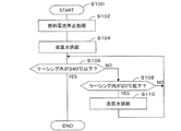
次に、燃料電池システム1の停止運転、特に燃料電池システム1の緊急停止時の作動について図2に示すフローチャートに沿って説明する。燃料電池システム1の緊急停止時には、制御装置15はステップS100にて緊急停止時改質水供給制御プログラムを起動し、燃料電池34の発電を停止させる(ステップS102)。具体的には、制御装置15は、ステップS102では、遮断弁11a1を閉止させるとともに原料ポンプ11a2の作動を停止させることで、改質用原料供給管11aから蒸発部32への改質用原料の供給を停止させる。さらに、カソードエアブロワ11c1の作動を停止させることで、カソードエア供給管11cから燃料電池34の空気流路34cへのカソードエアの供給を停止させる。また、接続管11a4の遮断弁11a5は通電が停止されて開放され、脱硫器11a3は改質用原料供給管11aだけでなく接続管11a4によってもケーシング31と連通した状態になる。
Next, the stop operation of the fuel cell system 1, particularly the operation at the time of emergency stop of the fuel cell system 1 will be described with reference to the flowchart shown in FIG. When the fuel cell system 1 is in an emergency stop, the
次に、制御装置15は、改質水ポンプ11b1を一定時間作動させて蒸発部32に改質水を供給する(ステップS104)。蒸発部32に供給された改質水は水蒸気となり、改質部33および燃料電池34の燃料流路34bを通ってケーシング31に供給され、ケーシング31内は水蒸気雰囲気となる。ケーシング31内は水蒸気雰囲気となることで、カソードエア供給管11cおよび排気管11dから外気(酸化剤ガス:カソードエア)が流入しないようになり、燃料電池34のセル34aが酸化されて劣化されないようになる。
Next, the
燃料電池34のセル34aは高温条件下(340℃以上)で酸化されやすく、ケーシング31内の水蒸気は温度の低下とともに凝縮して減少するので、制御装置15は、燃料電池34のセル34aが酸化剤ガスによって酸化されにくい温度として340℃以下となるまでケーシング31内を水蒸気雰囲気となるように制御する。制御装置15は、ステップS106において、温度センサ36によってケーシング31内の温度が340℃以下となったか否かを判定する。ケーシング31内の温度が340℃以下でなければ(340℃より高い場合)、制御装置15はステップS108,110によりケーシング31内を継続的に水蒸気雰囲気となるように制御する。
The
具体的には、制御装置15は、温度センサ36によってケーシング31内の温度が20℃低下したか否かを判定する(ステップS108)。制御装置15は、ステップS108において、ケーシング31内の温度が20℃低下していなければ「NO」と判断してステップS106に戻し、ケーシング31内の温度が20℃低下するまでステップS106,S108の処理を繰り返し実行する。
Specifically, the
ケーシング31内の温度が20℃低下する毎に、制御装置15は、ステップS108にて「YES」と判定し、ステップS110において、改質水ポンプ11b1を作動させて蒸発部32に改質水を供給する。制御装置15がステップS110にて改質水ポンプ11b1を作動させるときには、ケーシング31の温度が20℃低下したときにケーシング31内の水蒸気の凝縮量を補う水蒸気量を算出し、算出した水蒸気量となるように改質水ポンプ11b1の作動時間を制御する。このように、ケーシング31内の水蒸気が凝縮することで減少しても、凝縮した水蒸気量に応じた水蒸気が蒸発部32で生成されるので、ケーシング31内の水蒸気雰囲気を維持することができ、ケーシング31内に外気が流入するのを抑制することができる。
Every time the temperature in the
ケーシング31内の温度が340℃以下となるまでステップS106〜S110の処理を繰り返し実行することにより、ケーシング31内の水蒸気雰囲気が維持された状態で、ケーシング31内の温度が340℃以下となると、制御装置15はステップS106にて「YES」と判断してプログラムを終了する。このように、ケーシング31内には340℃より高い高温条件下で酸化剤ガスの流入が阻止され、燃料電池34のセル34aは酸化剤ガスによって酸化されず、セル34aの劣化を抑制することができる。
By repeatedly executing the processes of steps S106 to S110 until the temperature in the
また、緊急停止時改質水供給制御プログラムを実行しているときに、脱硫器11a3は燃料電池モジュール30のケーシング31の輻射熱を受けるととともに、改質用原料が通過しなくなることによって温度が約200℃から約250℃まで上昇する(停止運転開始時点から50℃昇温する。)。脱硫器11a3の脱硫剤は吸着していた改質用原料を脱離し、脱離された改質用原料は脱硫器11a3から接続管11a4に流れ出すが、脱離された改質用原料はバッファタンク11a6に一時的に滞留し、ケーシング31に流入されないようになる。このように、燃料電池システム1の停止運転を開始した後で、脱硫器11a3の脱硫剤が温度の上昇によって改質用原料を脱離しても、改質用原料はバッファタンク11a6によってケーシング31に流入せずに、改質用原料が燃料電池34のセル34aに析出(炭素析出)されないようになる(硫黄分による被毒も抑制することができる)。
Further, when the reforming water supply control program at the time of emergency stop is executed, the desulfurizer 11a3 receives the radiant heat of the
脱硫器11a3は上述したように一時的に温度が上昇するが、ケーシング31内の温度の低下とともに再び温度が下降する。脱硫器11a3は温度の低下とともにバッファタンク11a6に滞留していた改質用原料または/および水蒸気を吸着するようになる。脱硫器11a3が改質用原料を吸着して負圧化すると、ケーシング31内の気体が接続管11a4および改質用原料供給管11aを介して流入(逆流)する。ケーシング31内は上述したように常に水蒸気雰囲気とされているので、脱硫器11a3にもケーシング31から水蒸気が流入するため酸化剤ガスに曝されないようなる。これにより、脱硫器11a3の脱硫剤が酸化剤ガスによって酸化されて劣化するのを抑制することができる。なお、制御装置15は、脱硫器11a3による改質用原料の吸着量に応じた水蒸気量を算出し、算出した水蒸気量が生成されるようにステップS110における改質水ポンプ11b1の作動時間を制御してもよい。
As described above, the temperature of the desulfurizer 11a3 temporarily increases, but the temperature decreases again as the temperature in the
上述した説明から明らかなように、本実施形態に係る燃料電池システム1は、供給源Gsから直接供給され硫黄成分を含んでいる直接燃料、または、供給源Gsから供給され硫黄成分を含んでいる改質用原料が改質され生成された改質燃料と、酸化剤ガスとにより発電する燃料電池34と、供給源Gsと燃料電池34との間に設けられ、吸着剤を有し吸着質を脱離可能に吸着するとともに吸着剤は温度が高いほど吸着量が小さい特性を有する脱硫器11a3(吸着装置)と、改質水を蒸発させて水蒸気を生成して燃料電池34側に供給する蒸発部32と、蒸発部32に改質水を供給する改質水ポンプ11b1(改質水供給部)と、燃料電池34の直接燃料オフガスまたは改質燃料オフガスと、酸化剤オフガスとを燃焼させる燃焼部35と、燃料電池34、燃焼部35および蒸発部32を収容するケーシング31と、ケーシング31外から酸化剤ガスを供給するカソードエア供給管11cおよび/またはカソードエアブロワ11c1(酸化剤ガス供給部)と、燃焼部35で発生する燃焼排ガスをケーシング31外に排気する排気管11dおよび/または熱交換器12(排気部)と、改質水ポンプ11b1を制御する制御装置15と、ケーシング31内に設けられ燃料電池34の温度に相関する温度を検出する温度センサ36と、を備えた燃料電池システムである。制御装置15は、燃料電池システム1の停止運転をする際に、温度センサ36によって検出した温度に基づいて、改質水ポンプ11b1から蒸発部32への改質水の供給を制御する改質水供給制御部(ステップS104,110)を備えている。
As is clear from the above description, the fuel cell system 1 according to the present embodiment includes a direct fuel that is directly supplied from the supply source Gs and contains a sulfur component, or a sulfur fuel that is supplied from the supply source Gs. Provided between the reformed fuel produced by reforming the reforming raw material and the oxidant gas, the
これによれば、燃料電池システム1の停止運転をする際に、改質水ポンプ11b1から蒸発部32に供給される改質水から水蒸気が生成され、ひいてはケーシング31内は水蒸気により満たされる。その結果、ケーシング31内には外部から酸化剤ガス供給部または/および排気部を介して空気(酸化剤ガス)が流入(逆流)するのが抑制され、ケーシング31内に配置されている燃料電池34が空気によって酸化されて劣化するのを抑制することができる。また、ケーシング31内の水蒸気は、ケーシング31に連通されている脱硫器11a3にも流入可能であるため、温度変化に起因して脱硫器11a3内にガスが流入する場合に、ケーシング31内の水蒸気は脱硫器11a3内に流入する。その結果、ケーシング31内に外部から流入(逆流)した空気(酸化剤ガス)が脱硫器11a3に流入(逆流)するのが抑制され、脱硫器11a3が空気によって酸化されて劣化するのを抑制することができる。さらに、ケーシング31内の温度に応じて改質水ポンプ11b1から蒸発部32に改質水を供給するようにしているので、ケーシング31内の水蒸気が温度の低下によって凝縮して減少しても、その減少分だけさらに水蒸気を発生させ供給することができる。その結果、蒸発部32で水蒸気を発生させる得る限り、ケーシング31内を水蒸気で満たした状態とすることができ、ひいては、ケーシング31内に外部からの空気が逆流するのを抑制し、燃料電池34および脱硫器11a3の劣化を抑制することができる。
According to this, when the fuel cell system 1 is stopped, steam is generated from the reformed water supplied from the reformed water pump 11b1 to the
また、燃料電池システム1の停止運転が開始された後に、ケーシング31内の温度が徐々に低下すると、ケーシング31内の水蒸気が凝縮して減少するとともに、脱硫器11a3がガスを吸着するようになり、ケーシング31内および脱硫器11a3内にガスが逆流する。
Further, when the temperature in the
これに対して、改質水供給制御部は、温度センサ36によって検出した温度からケーシング31内の水蒸気の凝縮量を補う第一水蒸気量および脱硫器11a3における吸着質(改質料原料または直接燃料)の吸着量に応じた第二水蒸気量を算出し、算出した第一および第二水蒸気量の和である総水蒸気量に相当する水量の改質水を蒸発部32に供給するように改質水ポンプ11b1を制御する。
On the other hand, the reforming water supply control unit compensates the condensate amount of water vapor in the
これによれば、温度センサ36によって検出した温度からケーシング31内の水蒸気の凝縮量を補う第一水蒸気量および脱硫器11a3における吸着質の吸着量に応じた第二水蒸気量の和である総水蒸気量に相当する水量の改質水が、蒸発部32に供給される。その結果、燃料電池システム1の停止運転が停止された後に、ケーシング31内の温度が徐々に低下する際に発生する、ケーシング31および脱硫器11a3へのガスの逆流分を、水蒸気で補填することができる。よって、ケーシング31内および脱硫器11a3内を水蒸気で満たした状態とすることができる。したがって、ケーシング31内には外部から空気(酸化剤ガス)が流入(逆流)するのがより確実に抑制され、ケーシング31内に配置されている燃料電池34、および脱硫器11a3が空気によって酸化されて劣化するのをより確実に抑制することができる。
According to this, the total water vapor that is the sum of the first water vapor amount that compensates for the condensation amount of water vapor in the
また、燃料電池システム1の停止運転をする際に、供給源Gsからの改質用原料または直接燃料の供給が遮断されるため、脱硫器11a3内の温度はケーシング31からの輻射熱および改質用原料または直接燃料(吸着質)の不通過によって一時的に上昇し、脱硫器11a3に吸着されていた改質用原料または直接燃料が脱離される。この脱離された改質用原料または直接燃料が、改質部33または/および燃料電池34に到達すると、炭素析出などにより改質部33および燃料電池34が劣化する。
Further, when the fuel cell system 1 is stopped, the supply of the reforming raw material or the direct fuel from the supply source Gs is interrupted, so that the temperature in the desulfurizer 11a3 is the radiant heat from the
これに対して、燃料電池システム1は、ケーシング31と脱硫器11a3の導入口とを接続する接続管11a4と、接続管11a4に設けられ、通電時に閉状態となり非通電時に開状態となる遮断弁11a5(電磁開閉弁)と、接続管11a4に設けられ、脱硫器11a3からケーシング31内に流入する改質用原料または直接燃料を一時的に滞留させるバッファタンク11a6と、をさらに備えている。
In contrast, the fuel cell system 1 includes a connection pipe 11a4 that connects the
これによれば、燃料電池システム1の停止運転をする際に、接続管11a4に設けられた遮断弁11a5を開状態とすれば、脱硫器11a3に吸着されていた改質用原料または直接燃料が脱離されても、脱離された改質用原料または直接燃料は、接続管11a4を通ってバッファタンク11a6に流入し一時的に滞留させることができる。その結果、改質用原料または直接燃料がケーシング31内に流入するのを抑制することができ、改質部33および燃料電池34およびが改質用原料または直接燃料によって劣化するのを抑制することができる。
According to this, when the shut-off operation of the fuel cell system 1 is performed, if the shutoff valve 11a5 provided in the connection pipe 11a4 is opened, the reforming raw material or the direct fuel adsorbed by the desulfurizer 11a3 can be obtained. Even after desorption, the desorbed raw material for reforming or direct fuel can flow into the buffer tank 11a6 through the connection pipe 11a4 and be temporarily retained. As a result, the reforming raw material or direct fuel can be prevented from flowing into the
また、脱硫器11a3の温度が時間の経過とともに下降すると、脱硫器11a3が改質用原料または直接燃料を再び吸着することによって接続管11a4を通ってケーシング31側の気体(水蒸気、可燃性ガス、空気など)を吸引することになるが、脱硫器11a3には接続管11a4を通ってバッファタンク11a6に残留するガス(ひいてはケーシング31内の水蒸気)が流入するので、脱硫器11a3が酸化剤ガスによって酸化するのを抑制することができる。
Further, when the temperature of the desulfurizer 11a3 decreases with the passage of time, the desulfurizer 11a3 again adsorbs the raw material for reforming or direct fuel, thereby passing the gas on the
また、上述した実施形態では、燃料電池モジュール30の緊急停止時に緊急停止時改質水供給制御プログラムを実行させたときについて説明したが、燃料電池モジュール30の通常の停止運転時に緊急停止時改質水供給制御プログラムを実行したときにも上述したのと同様の作用効果を得ることができる。
In the above-described embodiment, the case where the emergency stop reforming water supply control program is executed at the time of emergency stop of the
なお、上述した実施形態においては、燃料電池モジュール11は、改質部33を省略する構成とすることもできる。このとき、燃料電池34の燃料流路34bには、改質ガス(改質燃料)に代えて、天然ガスや石炭ガスを水蒸気とともに供給すればよい。このように燃料電池34の燃料極に供給源Gsから直接供給され硫黄成分を含んでいる燃料を直接燃料とする。
In the above-described embodiment, the
また、上述した実施形態においては、温度センサ36に代えて、燃料電池34の温度を検出する温度センサを使用するようにしてもよく、改質部33の温度を検出する温度センサを使用するようにしてもよい。
In the embodiment described above, a temperature sensor that detects the temperature of the
1…燃料電池システム、10…発電ユニット、11…燃料電池モジュール、11a…改質用原料供給管、11a1…遮断弁、11a2…原料ポンプ、11a3…脱硫器、11a4…接続管、11a5…遮断弁(電磁開閉弁)、11a6…バッファタンク、11b…改質供給管、11b1…改質水ポンプ(改質水供給部)、11c…カソードエア供給管(酸化剤ガス供給部)、11c1…カソードエアブロワ(酸化剤ガス供給部)、15…制御装置、31…ケーシング、32蒸発部、33…改質部、34…燃料電池、35…燃焼部。 DESCRIPTION OF SYMBOLS 1 ... Fuel cell system, 10 ... Power generation unit, 11 ... Fuel cell module, 11a ... Raw material supply pipe for reforming, 11a1 ... Shut-off valve, 11a2 ... Raw material pump, 11a3 ... Desulfurizer, 11a4 ... Connection pipe, 11a5 ... Shut-off valve (Electromagnetic on-off valve), 11a6 ... buffer tank, 11b ... reformed supply pipe, 11b1 ... reformed water pump (reformed water supply section), 11c ... cathode air supply pipe (oxidant gas supply section), 11c1 ... cathode air Blower (oxidant gas supply unit), 15 ... control device, 31 ... casing, 32 evaporation unit, 33 ... reforming unit, 34 ... fuel cell, 35 ... combustion unit.
Claims (3)
前記供給源と前記燃料電池との間に設けられ、吸着剤を有し吸着質を脱離可能に吸着するとともに前記吸着剤は温度が高いほど吸着量が小さい特性を有する吸着装置と、
改質水を蒸発させて水蒸気を生成して前記燃料電池側に供給する蒸発部と、
前記蒸発部に前記改質水を供給する改質水供給部と、
前記燃料電池の直接燃料オフガスまたは改質燃料オフガスと、酸化剤オフガスとを燃焼させる燃焼部と、
前記燃料電池、前記燃焼部および前記蒸発部を収容するケーシングと、
前記ケーシング外から前記酸化剤ガスを供給する酸化剤ガス供給部と、
前記燃焼部で発生する燃焼排ガスを前記ケーシング外に排気する排気部と、
前記改質水供給部を制御する制御装置と、
前記ケーシング内に設けられ前記燃料電池の温度に相関する温度を検出する温度センサと、
を備えた燃料電池システムであって、
前記制御装置は、前記燃料電池システムの停止運転をする際に、前記温度センサによって検出した前記温度に基づいて、前記改質水供給部から前記蒸発部への前記改質水の供給を制御する改質水供給制御部を備えた燃料電池システム。 Power generation from direct fuel containing sulfur component supplied directly from a source or reformed fuel generated from reforming raw material containing sulfur component supplied from a source and oxidant gas A fuel cell,
An adsorbing device that is provided between the supply source and the fuel cell and has an adsorbent and adsorbably adsorbates so that the adsorbent has a smaller amount of adsorption as the temperature increases;
An evaporation section for evaporating the reformed water to generate water vapor and supplying the water vapor to the fuel cell side;
A reforming water supply unit for supplying the reforming water to the evaporation unit;
A combustion section for burning direct fuel offgas or reformed fuel offgas of the fuel cell and oxidant offgas;
A casing that houses the fuel cell, the combustion section, and the evaporation section;
An oxidant gas supply unit for supplying the oxidant gas from outside the casing;
An exhaust part for exhausting combustion exhaust gas generated in the combustion part to the outside of the casing;
A control device for controlling the reforming water supply unit;
A temperature sensor provided in the casing for detecting a temperature correlated with the temperature of the fuel cell;
A fuel cell system comprising:
The control device controls supply of the reformed water from the reformed water supply unit to the evaporation unit based on the temperature detected by the temperature sensor when the fuel cell system is stopped. A fuel cell system including a reformed water supply control unit.
前記ケーシングと前記吸着装置の導入口とを接続する接続管と、
前記接続管に設けられ、通電時に閉状態となり非通電時に開状態となる電磁開閉弁と、
前記接続管に設けられ、前記吸着装置から前記ケーシング内に流入する前記改質用原料または前記直接燃料を一時的に滞留させるバッファタンクと、
をさらに備えた請求項1または請求項2記載の燃料電池システム。 The fuel cell system includes:
A connecting pipe connecting the casing and the inlet of the adsorption device;
An electromagnetic on-off valve provided in the connecting pipe, which is closed when energized and opened when de-energized;
A buffer tank provided in the connection pipe and temporarily retaining the reforming raw material or the direct fuel flowing into the casing from the adsorption device;
The fuel cell system according to claim 1, further comprising:
Priority Applications (1)
| Application Number | Priority Date | Filing Date | Title |
|---|---|---|---|
| JP2016032371A JP6707894B2 (en) | 2016-02-23 | 2016-02-23 | Fuel cell system |
Applications Claiming Priority (1)
| Application Number | Priority Date | Filing Date | Title |
|---|---|---|---|
| JP2016032371A JP6707894B2 (en) | 2016-02-23 | 2016-02-23 | Fuel cell system |
Publications (2)
| Publication Number | Publication Date |
|---|---|
| JP2017152148A true JP2017152148A (en) | 2017-08-31 |
| JP6707894B2 JP6707894B2 (en) | 2020-06-10 |
Family
ID=59739803
Family Applications (1)
| Application Number | Title | Priority Date | Filing Date |
|---|---|---|---|
| JP2016032371A Expired - Fee Related JP6707894B2 (en) | 2016-02-23 | 2016-02-23 | Fuel cell system |
Country Status (1)
| Country | Link |
|---|---|
| JP (1) | JP6707894B2 (en) |
Citations (6)
| Publication number | Priority date | Publication date | Assignee | Title |
|---|---|---|---|---|
| JP2005340075A (en) * | 2004-05-28 | 2005-12-08 | Kyocera Corp | How to shut down the fuel cell |
| JP2010238417A (en) * | 2009-03-30 | 2010-10-21 | Aisin Seiki Co Ltd | Solid oxide fuel cell system |
| JP2011076846A (en) * | 2009-09-30 | 2011-04-14 | Noritz Corp | Stopping method for solid oxide fuel cell |
| JP2012113991A (en) * | 2010-11-25 | 2012-06-14 | Jx Nippon Oil & Energy Corp | Fuel cell system |
| JP2013089402A (en) * | 2011-10-17 | 2013-05-13 | Aisin Seiki Co Ltd | Fuel cell system |
| JP2016122507A (en) * | 2014-12-24 | 2016-07-07 | 株式会社ノーリツ | Solid oxide type fuel battery |
-
2016
- 2016-02-23 JP JP2016032371A patent/JP6707894B2/en not_active Expired - Fee Related
Patent Citations (6)
| Publication number | Priority date | Publication date | Assignee | Title |
|---|---|---|---|---|
| JP2005340075A (en) * | 2004-05-28 | 2005-12-08 | Kyocera Corp | How to shut down the fuel cell |
| JP2010238417A (en) * | 2009-03-30 | 2010-10-21 | Aisin Seiki Co Ltd | Solid oxide fuel cell system |
| JP2011076846A (en) * | 2009-09-30 | 2011-04-14 | Noritz Corp | Stopping method for solid oxide fuel cell |
| JP2012113991A (en) * | 2010-11-25 | 2012-06-14 | Jx Nippon Oil & Energy Corp | Fuel cell system |
| JP2013089402A (en) * | 2011-10-17 | 2013-05-13 | Aisin Seiki Co Ltd | Fuel cell system |
| JP2016122507A (en) * | 2014-12-24 | 2016-07-07 | 株式会社ノーリツ | Solid oxide type fuel battery |
Also Published As
| Publication number | Publication date |
|---|---|
| JP6707894B2 (en) | 2020-06-10 |
Similar Documents
| Publication | Publication Date | Title |
|---|---|---|
| JP6946833B2 (en) | Fuel cell system | |
| EP2924788B1 (en) | Fuel cell system | |
| JP7127427B2 (en) | fuel cell system | |
| WO2010087167A1 (en) | Fuel processing device, fuel cell system provided therewith, and method for operating a fuel processing device | |
| JP7010022B2 (en) | Fuel cell system | |
| JP6638464B2 (en) | Fuel cell system | |
| JP7711559B2 (en) | Fuel Cell Systems | |
| JP4855688B2 (en) | Fuel cell power generation system | |
| JP6707894B2 (en) | Fuel cell system | |
| JP2009076392A (en) | Liquid fuel cell power generation system | |
| JP2017152149A (en) | Fuel battery system | |
| JP6424494B2 (en) | Fuel cell system | |
| JP2021166129A (en) | Fuel cell system | |
| JP6938918B2 (en) | Fuel cell system | |
| JP6904114B2 (en) | Fuel cell system | |
| JP2010108770A (en) | Fuel cell power generation system, and control method of fuel cell power generation system | |
| JP7439622B2 (en) | fuel cell system | |
| JP6483359B2 (en) | Fuel cell system | |
| JP2022186361A (en) | fuel cell system | |
| JP2009009886A (en) | Fuel cell | |
| JP2016012521A (en) | Fuel cell system | |
| JP2024071845A (en) | Fuel Cell Systems | |
| JP2025130506A (en) | fuel cell system | |
| JP7574677B2 (en) | Fuel Cell Systems | |
| JP7484351B2 (en) | Fuel Cell Systems |
Legal Events
| Date | Code | Title | Description |
|---|---|---|---|
| A621 | Written request for application examination |
Free format text: JAPANESE INTERMEDIATE CODE: A621 Effective date: 20190110 |
|
| A977 | Report on retrieval |
Free format text: JAPANESE INTERMEDIATE CODE: A971007 Effective date: 20191030 |
|
| A131 | Notification of reasons for refusal |
Free format text: JAPANESE INTERMEDIATE CODE: A131 Effective date: 20191105 |
|
| A521 | Request for written amendment filed |
Free format text: JAPANESE INTERMEDIATE CODE: A523 Effective date: 20191223 |
|
| TRDD | Decision of grant or rejection written | ||
| A01 | Written decision to grant a patent or to grant a registration (utility model) |
Free format text: JAPANESE INTERMEDIATE CODE: A01 Effective date: 20200421 |
|
| A61 | First payment of annual fees (during grant procedure) |
Free format text: JAPANESE INTERMEDIATE CODE: A61 Effective date: 20200504 |
|
| R151 | Written notification of patent or utility model registration |
Ref document number: 6707894 Country of ref document: JP Free format text: JAPANESE INTERMEDIATE CODE: R151 |
|
| LAPS | Cancellation because of no payment of annual fees |