JP2017155481A - stabilizer - Google Patents
stabilizer Download PDFInfo
- Publication number
- JP2017155481A JP2017155481A JP2016039596A JP2016039596A JP2017155481A JP 2017155481 A JP2017155481 A JP 2017155481A JP 2016039596 A JP2016039596 A JP 2016039596A JP 2016039596 A JP2016039596 A JP 2016039596A JP 2017155481 A JP2017155481 A JP 2017155481A
- Authority
- JP
- Japan
- Prior art keywords
- stirring
- mixing
- unit
- agitation
- stabilizer
- Prior art date
- Legal status (The legal status is an assumption and is not a legal conclusion. Google has not performed a legal analysis and makes no representation as to the accuracy of the status listed.)
- Pending
Links
- 239000003381 stabilizer Substances 0.000 title claims abstract description 21
- 239000002689 soil Substances 0.000 claims abstract description 11
- 238000013019 agitation Methods 0.000 claims abstract description 10
- 238000003756 stirring Methods 0.000 claims description 68
- 238000009412 basement excavation Methods 0.000 description 4
- 238000000034 method Methods 0.000 description 4
- 239000004575 stone Substances 0.000 description 3
- 239000000463 material Substances 0.000 description 2
- 230000005540 biological transmission Effects 0.000 description 1
- 239000004568 cement Substances 0.000 description 1
- 238000007796 conventional method Methods 0.000 description 1
- 230000000694 effects Effects 0.000 description 1
- 238000003825 pressing Methods 0.000 description 1
- 239000004576 sand Substances 0.000 description 1
- 239000002344 surface layer Substances 0.000 description 1
Images


Landscapes
- Consolidation Of Soil By Introduction Of Solidifying Substances Into Soil (AREA)
Abstract
Description
本発明は、スタビライザーに関するものである。 The present invention relates to a stabilizer.
ここでいうスタビライザーは、土壌の表面を撹拌混合し、また固化材との混合も可能にするものである。構造的には、ブルドーザの前方ブレードに替えて、撹拌混合部を取り付けたものや、キャタピラーでなく、タイヤ型であってその前方のタイヤと後方のタイヤとの間に回転撹拌部を取り付けたもの等がある。 The stabilizer referred to here is to stir and mix the surface of the soil and also to mix with the solidified material. Structurally, instead of the front blade of a bulldozer, a stirrer / mixer is attached, or it is not a caterpillar but a tire type with a rotating stirrer attached between the front tire and the rear tire Etc.
このスタビライザーは、表面土壌の強度が不足する場合、その土壌に固化材(セメント等)や、他の土壌を加えて撹拌混合するためのものである。撹拌するための回転切削刃(刃状でないものも刃と呼ぶ)を多数有するものである。 This stabilizer is for adding a solidifying material (cement or the like) or other soil to the soil and stirring and mixing it when the strength of the surface soil is insufficient. It has a large number of rotary cutting blades for stirring (those that are not blade-like are also called blades).
また、最近では、特許文献1のようなパワーショベルのショベル部分に回転刃(撹拌刃)を設けたものも考案されている。
In addition, recently, there has been devised one in which a shovel portion of a power shovel as in
しかしながら、従来のブルドーザ型のスタビライザーでは、狭い土地を施工する場合、撹拌混合部が回転(パワーショベルのように走行部以外の上部工作部分が走行部に対して回転すること)できないため施工できない部分が生じる。バック走行だけでは、必ず残る部分があるのである。 However, in the conventional bulldozer type stabilizer, when constructing a narrow land, the stirring and mixing part cannot rotate (the upper work part other than the traveling part cannot rotate with respect to the traveling part like a power shovel). Occurs. There is always a part left by just running back.
結局このような残った部分は、別途小型の特許文献1のようなパワーショベルを用いて行うしかなかった。しかし、パワーショベルのアームに撹拌機が固定されたものでは、アームが邪魔であるばかりか、撹拌時の下方への押圧力も小さく、深さを一定にしての走行も難しい。
そこで、できるだけ、撹拌混合されていない部分が残らないような使いやすいスタビライザーを提供する。
Eventually, such a remaining portion could only be carried out using a separate power shovel as in
Therefore, an easy-to-use stabilizer is provided so that as much as possible a part that is not stirred and mixed remains.
以上のような状況に鑑み、本発明者は鋭意研究の結果本発明スタビライザーを完成したものであり、その特徴とするところは、キャタピラーによって走行する走行部と、該走行部に支持され且つ回転可能な回転部からなり、該回転部には操作者が操作する操作室があり、かつ該回転部には、土壌を撹拌混合する撹拌混合部が、垂直方向に平行四辺形を形成する平行な2本の連結部によって連結されている点にある。 In view of the above situation, the present inventor has completed the stabilizer of the present invention as a result of diligent research. The feature of the present inventor is that the traveling unit travels by a caterpillar, and is supported and rotatable by the traveling unit. The rotating unit has an operation chamber operated by an operator, and the rotating unit includes a stirring and mixing unit configured to stir and mix the soil. It is in the point connected by the connection part of a book.
ここでいう走行部は、キャタピラーによって走行する部分であり、これに種々の装置を載置、逆にいうと走行部が種々の装置を支持して走行するのである。これは、一般的なパワーショベル等の走行部でよい。
本発明では、タイヤではなくキャタピラーに限定している。これは、軟弱地盤(土壌)に使用するためである。
Here, the traveling unit is a portion that travels by the caterpillar, and various devices are placed on the traveling unit. In other words, the traveling unit travels while supporting the various devices. This may be a traveling unit such as a general power shovel.
In the present invention, it is limited to a caterpillar, not a tire. This is for use on soft ground (soil).
回転部は、走行部に支持されており、また走行部に対して水平回転可能である。この回転については、パワーショベルと同様の機構でよい。また、この回転部には操作室があり、操作する者が乗って操作する。 The rotating part is supported by the traveling part and can be rotated horizontally with respect to the traveling part. About this rotation, the mechanism similar to a power shovel may be sufficient. In addition, this rotating unit has an operation room on which an operator operates.
この回転部には、土壌を撹拌混合する撹拌混合部が連結されている。撹拌混合部とは、回転軸とその軸に固定された撹拌刃からなるものである。実際には、回転軸を支持する支持部、回転駆動するためのモーター(電動や油圧等)、モーターと回転軸を連結するチェーン等の伝達具等を有している。
この撹拌混合部が、上記した回転部に連結されているのであるが、その連結の方法が本発明の第1のポイントである。本発明では、垂直方向に平行四辺形を形成する平行な2本の連結部によって連結されている。ここでいう平行四辺形は、この上下の2本の連結部の可回転の連結箇所4箇所が構成する形状である。攪拌混合部や連結部自体の形状をいうのではない。
このように平行四辺形を形成するように固定しているのは、撹拌混合部を上下させても、地面との水平を保つためである。
この平行四辺形を形成する連結部は、左右両方に設けるのが良い。
An agitation and mixing unit for agitating and mixing the soil is connected to the rotating unit. The stirring and mixing unit is composed of a rotating shaft and a stirring blade fixed to the shaft. Actually, it has a support portion for supporting the rotating shaft, a motor for rotating and driving (electrical or hydraulic), a transmission tool such as a chain for connecting the motor and the rotating shaft, and the like.
The stirring and mixing unit is connected to the rotating unit described above, and the connection method is the first point of the present invention. In the present invention, they are connected by two parallel connecting portions that form a parallelogram in the vertical direction. The parallelogram referred to here is a shape formed by four rotatable connecting portions of the upper and lower connecting portions. It does not mean the shape of the stirring and mixing part or the connecting part itself.
The reason why the parallelogram is fixed in this way is to maintain the level with the ground even if the stirring and mixing unit is moved up and down.
The connecting portions forming this parallelogram are preferably provided on both the left and right sides.
この撹拌混合部を上下させる方法は、エアーや油圧のシリンダーによって駆動すればよい。シリンダーの取付場所は自由であり、平行四辺形を変形させることができる位置であればどこでもよい。例えば、平行四辺形の撹拌混合部の下方点と、回転部の前方上部をシリンダー駆動部で連結する、平行四辺形の回転部側の下方点と攪拌混合部側と連結する等であるが、限定するものではない。このシリンダーも中心に1本でも、左右に1本づつ設けてもよい。 The method of moving the stirring and mixing unit up and down may be driven by an air or hydraulic cylinder. The mounting position of the cylinder is arbitrary, and any position can be used as long as the parallelogram can be deformed. For example, the lower point of the parallelogram stirring and mixing unit and the front upper part of the rotating unit are connected by a cylinder driving unit, the lower point of the parallelogram rotating unit and the stirring and mixing unit side, etc. It is not limited. One cylinder may be provided at the center or one cylinder at the left and right.
撹拌混合部には、掘削(撹拌)深さ調整用のスキー部が設けられている。このスキー部は、少なくとも地表に沿う水平に長い部材を有している。通常は、このスキー部と撹拌混合部は、上下に関しては一定距離フリーにしておく。即ち、撹拌混合部(即ち撹拌刃)を地中に入れるときに、他の部材は撹拌刃とともに下降するが、スキー部はその下面が、地表に接した時点から、それ以降は下降しないようにするためである。その方法は、長孔を介して支持し、その長孔の中では上下フリーであり、前後左右にはフリーでない。勿論、長孔の上下の端部に至るとそこからは同伴することは言うまでもない。
そして、このスキー部が接した状態で走行すれば、掘削深さが容易に一定にできる。パワーショベルのようなバケットに撹拌混合部が固定されるものでは、水平に保って移動することは非常に難しい。
The agitation / mixing part is provided with a ski part for adjusting excavation (agitation) depth. This ski part has at least a horizontally long member along the ground surface. Usually, the ski part and the agitation / mixing part are free for a certain distance in the vertical direction. That is, when the stirring and mixing unit (that is, the stirring blade) is put into the ground, the other members are lowered together with the stirring blade, but the ski portion is not lowered after the bottom surface is in contact with the ground surface. It is to do. The method is supported through a long hole, and is vertically free in the long hole and is not free in the front, back, left, and right. Of course, it goes without saying that the upper and lower ends of the long hole are accompanied by the end.
And if it drive | works with this ski part in contact, excavation depth can be made constant easily. If the stirring and mixing unit is fixed to a bucket such as a power shovel, it is very difficult to keep it moving horizontally.
スキー部は、攪拌混合部とはフリーでなく、調整可能に固定されてもよい。例えば、攪拌混合部と油圧シリンダーによって連結され、攪拌混合部とレベルを調整でき、その位置で固定もできる方法である。ここで700mmと固定すれば、それは再調整するまでは変わらないため、掘削深さがより一定に保つことができる。 The ski unit is not free from the stirring and mixing unit, and may be fixed so as to be adjustable. For example, the stirring and mixing unit is connected to the hydraulic cylinder, the level can be adjusted with the stirring and mixing unit, and the position can be fixed. If 700 mm is fixed here, it does not change until readjustment, so that the excavation depth can be kept more constant.
上記したスキー部と、攪拌混合部とのレベル(高さ)の差を、操作室から認識できるように、攪拌混合部に操作室から見えるメジャーを設け、スキー部に固定された指示具を設けておくのがよい。その指示具の位置を見ればレベルの差が読み取れるようする。
これは、スキー部がフリーの場合でも固定の場合でも使用できる。
In order to be able to recognize the difference in level (height) between the ski part and the stirring and mixing part from the operation room, a measure that can be seen from the operation room is provided in the stirring and mixing part, and an indicator fixed to the ski part is provided. It is good to keep. The level difference can be read by looking at the position of the indicator.
This can be used whether the ski is free or fixed.
このスキー部か、又は撹拌混合部にはカバーを設けても良い。カバーは撹拌刃によって土壌や石、砂等が周囲に飛散するのをある程度防止する。 You may provide a cover in this ski part or the stirring and mixing part. The cover prevents the scattering of soil, stones, sand, etc. to some extent by the stirring blade.
回転軸(撹拌刃)の駆動は、撹拌混合部の中に設けられたモーターで行うのが一般的である。モーターと回転軸はチェーンで伝達するのがよい。この回転軸にチェーンを掛ける部分は、当然撹拌部分(撹拌刃)の外側にある。中にあれば、その部分には撹拌刃が取り付けられず、撹拌できない部分ができてしまうためである。
そして、このチェーンが掛かっている部分(通常はカバーされている)は、当然ながら地表から下には行かない。ということは、回転軸は地表面より下には行かないということである。
The rotation shaft (stirring blade) is generally driven by a motor provided in the stirring and mixing unit. The motor and rotating shaft should be transmitted by a chain. The part where the chain is hung on the rotating shaft is naturally outside the stirring part (stirring blade). If it is inside, a stirring blade is not attached to that part, and a part that cannot be stirred is created.
And the part of the chain (usually covered) does not go down from the surface. This means that the axis of rotation does not go below the ground surface.
このため、掘削(撹拌)深さは、撹拌刃の径で決まることになる。より、深く掘削しようとすると、撹拌刃の径を大きくするしかないのである。しかし、これは非常にコストのかかることである。 For this reason, the excavation (stirring) depth is determined by the diameter of the stirring blade. In order to dig deeper, the diameter of the stirring blade must be increased. However, this is very expensive.
そこで、チェーンによって駆動される回転軸(地表までしか下降できない)の内側にギアを設けて、そのギアの下方でかみ合うギアを持った回転軸を設けて、それに撹拌刃を設けてもよい。このようにすると、撹拌刃の回転軸が、チェーンによって駆動される回転軸より下方にあるため、より深く掘削ができる。 Therefore, a gear may be provided inside a rotating shaft (which can only be lowered to the ground surface) driven by a chain, a rotating shaft having a gear meshing below the gear may be provided, and a stirring blade may be provided thereon. If it does in this way, since the rotating shaft of a stirring blade exists below the rotating shaft driven by a chain, it can dig deeper.
更に、回転部には、リッパーを設けてもよい。リッパーとは、犂と同様のもので土を掘り起こし、大きな石や根等を除去するためのものである。取り付け場所としては、撹拌混合部と反対側に付けるのが良い。複数個(3〜6本)設けるのが良い。 Furthermore, you may provide a ripper in a rotation part. The ripper is the same as the ridge and is used to dig up soil and remove large stones and roots. As an attachment place, it is good to attach to the side opposite to the stirring and mixing unit. It is preferable to provide a plurality (3 to 6).
また、走行部がキャタピラーであるため、横方向に移動することはできず、少しでも横の部分を撹拌混合するのは非常に手間がかかる。これを解消するため、この撹拌混合部は、左右に平行移動できるようにしてもよい。例えば、水平なシリンダーを前記連結部に設け、撹拌混合部をそのシリンダー内のピストンに設けて、そのピストンが油圧で左右に移動できるようにすればよい。 Moreover, since the traveling part is a caterpillar, it cannot move in the lateral direction, and it is very troublesome to mix and stir the horizontal part even a little. In order to solve this problem, the stirring and mixing unit may be allowed to move in parallel from side to side. For example, a horizontal cylinder may be provided in the connecting portion, and a stirring and mixing portion may be provided in a piston in the cylinder so that the piston can be moved to the left and right by hydraulic pressure.
本発明スタビライザーには次のような効果がある。
(1) スタビライザーであるにもかかわらず、操作部が回転可能であり、細かい移動ができる。
(2) 連結部が平行四辺形であり、撹拌混合部が地表と平行を保ったまま上下できる。
(3) スキー部を設けたものでは、一定深さでの走行が非常に容易である。
(4) 撹拌混合部を横移動可能にしたものでは、微調整ができ狭い部分でも効率よく表層改良できる。
(5) リッパーを設けたものでは、大きな石や根等も容易に除去できる。
The stabilizer of the present invention has the following effects.
(1) Despite being a stabilizer, the operation unit is rotatable and can be moved finely.
(2) The connecting part is a parallelogram, and the stirring and mixing part can be moved up and down while keeping parallel to the ground surface.
(3) With a ski section, traveling at a certain depth is very easy.
(4) In the case where the stirring and mixing unit is laterally movable, fine adjustment can be performed and the surface layer can be improved efficiently even in a narrow portion.
(5) With a ripper, large stones and roots can be easily removed.
以下実施例に基づいて、本発明をより詳細に説明する。
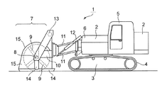
図1は、本発明スタビライザー1の1例を示す側面図である。回転部2は走行部3に回転可能に支持されている。回転可能に支持する方法は、従来のパワーショベル等と同様の機構でよい。本発明では、走行部3はキャタピラー4によって移動する。これは軟弱地盤等ではタイヤ走行は無理であるためである。
Hereinafter, based on an Example, this invention is demonstrated in detail.
FIG. 1 is a side view showing an example of the
この回転部2の操作部5の前部6に撹拌混合部7が固定されている。この撹拌混合部7は、回転軸8と撹拌刃9を有している。この回転軸8は支持部10に支持され、この支持部10が連結部11によって前記前部6に連結されている。
A stirring and mixing
また、撹拌混合部7を上下させるために、油圧シリンダー12が、平行四辺形を形成する連結部11の撹拌混合部側の下の点(左右には少しずれている)と前部6に接続されている。この油圧シリンダー12は平行四辺形を変形でき、撹拌混合部を上下できればどこに設けてもよい。この例では、油圧シリンダー12は左右に1対設けている。
Further, in order to move the stirring and mixing
支持部10の上部にはモーター13が設けられ、チェーン19によって回転軸8を駆動している。
A
また、支持部10にはスキー部14が設けられている。地表に沿うようにスキーのような形状である。勿論、形状は限定しない。この例では、この支持部10にはカバー15も取り付けている。
In addition, the
図2は、本発明スタビライザー1の撹拌混合部7が上下しているところを示す側面図である。連結部11の変形に従って撹拌混合部7が上下し、当然回転軸8が上下している。しかし、スキー部14は、その下面が地面に接したままで、上下はしていない。これは、撹拌混合部7が、スキー部14に対して、上下に関して一定距離フリーになっているためである。
FIG. 2 is a side view showing the stirring and mixing
図3は、本発明の撹拌混合部7の平面図である。連結部11が左右(この図では上下)一対設けられているのがわかる。油圧シリンダー12も一対設けられている。回転軸8に撹拌刃9が固定されているが、一部のみ記載している。刃はどのような形状でもよい。
この例では、撹拌混合部7の手前側(この図では右側)にピストン17とシリンダー16が設けられている。このシリンダー16側に連結部11が固定され、ピストン17側に撹拌混合部7が連結されている。
ピストン17とシリンダー16を相対的に移動すれば、撹拌混合部7が左右に平行移動することになる。
FIG. 3 is a plan view of the stirring and mixing
In this example, a
If the
図4は、撹拌刃の駆動部を示す。(a)は、従来の方法であり、(b)はギアを介して駆動する例である。(a)では、チェーンカバー18内に、チェーン19が掛けられたスプロケット20がある。このスプロケット20の軸と撹拌刃のついた回転軸8とは同軸である。よって、撹拌刃の回転軸は、これ以上深くは下降できない。
(b)は、スプロケット20と同軸でギア21を設け、そのギア21とかみ合うギア22を回転軸8に設けている。このようにすると、撹拌刃が同じ径であっても、スプロケット20と回転軸8の高さの差だけ、深く掘削できる。この例では、チェーンカバー18が上記2つのギアもカバーしている。また、ギアに近い部分の撹拌刃9は、このギアをカバーする部分も掘削できるように刃が長くなっている。ここを掘削しなければ、ギアの部分が地表より下方に進まないためである。
FIG. 4 shows the drive unit of the stirring blade. (A) is a conventional method, and (b) is an example of driving through a gear. In (a), the
In (b), a
1 本発明スタビライザー
2 回転部
3 走行部
4 キャタピラー
5 操作部
6 前部
7 撹拌混合部
8 回転軸
9 撹拌刃
10 支持部
11 連結部
12 油圧シリンダー
13 モーター
14 スキー部
15 カバー
16 シリンダー
17 ピストン
18 チェーンカバー
19 チェーン
20 スプロケット
21 ギア
22 ギア
DESCRIPTION OF
Claims (5)
The stabilizer according to any one of claims 1 to 4, wherein the rotating shaft has a gear engaged with a gear provided on a shaft driven by a motor through a chain.
Priority Applications (1)
| Application Number | Priority Date | Filing Date | Title |
|---|---|---|---|
| JP2016039596A JP2017155481A (en) | 2016-03-02 | 2016-03-02 | stabilizer |
Applications Claiming Priority (1)
| Application Number | Priority Date | Filing Date | Title |
|---|---|---|---|
| JP2016039596A JP2017155481A (en) | 2016-03-02 | 2016-03-02 | stabilizer |
Publications (1)
| Publication Number | Publication Date |
|---|---|
| JP2017155481A true JP2017155481A (en) | 2017-09-07 |
Family
ID=59809383
Family Applications (1)
| Application Number | Title | Priority Date | Filing Date |
|---|---|---|---|
| JP2016039596A Pending JP2017155481A (en) | 2016-03-02 | 2016-03-02 | stabilizer |
Country Status (1)
| Country | Link |
|---|---|
| JP (1) | JP2017155481A (en) |
Cited By (1)
| Publication number | Priority date | Publication date | Assignee | Title |
|---|---|---|---|---|
| JP2022046975A (en) * | 2020-09-11 | 2022-03-24 | 株式会社オクノコトー | stabilizer |
Citations (7)
| Publication number | Priority date | Publication date | Assignee | Title |
|---|---|---|---|---|
| JPS52136402U (en) * | 1976-04-13 | 1977-10-17 | ||
| JPS5576206U (en) * | 1978-11-15 | 1980-05-26 | ||
| JPS6277207U (en) * | 1985-10-29 | 1987-05-18 | ||
| JPH07268860A (en) * | 1994-03-31 | 1995-10-17 | Komatsu Esuto:Kk | Soil improvement machine |
| JPH0841865A (en) * | 1994-07-27 | 1996-02-13 | Komatsu Esuto:Kk | Civil engineering construction machinery |
| JPH08193323A (en) * | 1995-01-17 | 1996-07-30 | Fumio Kinoshita | Bucket with stirrer |
| JPH108453A (en) * | 1996-06-19 | 1998-01-13 | Komatsu Est Corp | Drilling mixing stirrer |
-
2016
- 2016-03-02 JP JP2016039596A patent/JP2017155481A/en active Pending
Patent Citations (7)
| Publication number | Priority date | Publication date | Assignee | Title |
|---|---|---|---|---|
| JPS52136402U (en) * | 1976-04-13 | 1977-10-17 | ||
| JPS5576206U (en) * | 1978-11-15 | 1980-05-26 | ||
| JPS6277207U (en) * | 1985-10-29 | 1987-05-18 | ||
| JPH07268860A (en) * | 1994-03-31 | 1995-10-17 | Komatsu Esuto:Kk | Soil improvement machine |
| JPH0841865A (en) * | 1994-07-27 | 1996-02-13 | Komatsu Esuto:Kk | Civil engineering construction machinery |
| JPH08193323A (en) * | 1995-01-17 | 1996-07-30 | Fumio Kinoshita | Bucket with stirrer |
| JPH108453A (en) * | 1996-06-19 | 1998-01-13 | Komatsu Est Corp | Drilling mixing stirrer |
Cited By (2)
| Publication number | Priority date | Publication date | Assignee | Title |
|---|---|---|---|---|
| JP2022046975A (en) * | 2020-09-11 | 2022-03-24 | 株式会社オクノコトー | stabilizer |
| JP7457363B2 (en) | 2020-09-11 | 2024-03-28 | 株式会社オクノコトー | stabilizer |
Similar Documents
| Publication | Publication Date | Title |
|---|---|---|
| KR20080110773A (en) | boring machine | |
| JPH10309108A (en) | Self-propelled excavator | |
| JP5603632B2 (en) | Mud agitator | |
| JP4391106B2 (en) | Ground stirring device and ground improvement method | |
| CN210507407U (en) | Shallow middle layer soil body continuous solidification agitated vessel | |
| JP6307459B2 (en) | Ground improvement device | |
| JP2009142152A (en) | Levee plastering machine | |
| JP5139406B2 (en) | Ground improvement machine | |
| JP2009121135A (en) | Bucket with rolling plate, for improving intermediate ground layer | |
| US606987A (en) | clark | |
| JP2002371586A (en) | Underground wall construction machine | |
| JP4285691B2 (en) | Ground agitator | |
| JP4516977B2 (en) | Underground pile forming apparatus and forming method | |
| JP2011200150A (en) | Ridge-forming machine | |
| JP2003328348A (en) | Soil agitator | |
| CN207118242U (en) | A kind of laser scraper | |
| JP3648439B2 (en) | Ground improvement stirrer and ground improvement method | |
| JPH0520094Y2 (en) | ||
| JP7719670B2 (en) | Mixing device and mechanical mixing method using the same | |
| JP7561394B1 (en) | Ground improvement machine | |
| JP6526538B2 (en) | Ground improvement device | |
| JP5189223B1 (en) | Ground improvement device | |
| JP5839464B2 (en) | Ground improvement machine and ground improvement method | |
| JP7457363B2 (en) | stabilizer | |
| JPH0748762Y2 (en) | Ditcher |
Legal Events
| Date | Code | Title | Description |
|---|---|---|---|
| A621 | Written request for application examination |
Free format text: JAPANESE INTERMEDIATE CODE: A621 Effective date: 20190108 |
|
| A977 | Report on retrieval |
Free format text: JAPANESE INTERMEDIATE CODE: A971007 Effective date: 20191018 |
|
| A131 | Notification of reasons for refusal |
Free format text: JAPANESE INTERMEDIATE CODE: A131 Effective date: 20191118 |
|
| A02 | Decision of refusal |
Free format text: JAPANESE INTERMEDIATE CODE: A02 Effective date: 20200519 |