JP2017155698A - Multiple-purpose vehicle - Google Patents
Multiple-purpose vehicle Download PDFInfo
- Publication number
- JP2017155698A JP2017155698A JP2016041387A JP2016041387A JP2017155698A JP 2017155698 A JP2017155698 A JP 2017155698A JP 2016041387 A JP2016041387 A JP 2016041387A JP 2016041387 A JP2016041387 A JP 2016041387A JP 2017155698 A JP2017155698 A JP 2017155698A
- Authority
- JP
- Japan
- Prior art keywords
- engine
- gear transmission
- fuel supply
- fuel
- gear
- Prior art date
- Legal status (The legal status is an assumption and is not a legal conclusion. Google has not performed a legal analysis and makes no representation as to the accuracy of the status listed.)
- Granted
Links
Images


Classifications
-
- F—MECHANICAL ENGINEERING; LIGHTING; HEATING; WEAPONS; BLASTING
- F02—COMBUSTION ENGINES; HOT-GAS OR COMBUSTION-PRODUCT ENGINE PLANTS
- F02D—CONTROLLING COMBUSTION ENGINES
- F02D41/00—Electrical control of supply of combustible mixture or its constituents
- F02D41/02—Circuit arrangements for generating control signals
- F02D41/021—Introducing corrections for particular conditions exterior to the engine
- F02D41/0215—Introducing corrections for particular conditions exterior to the engine in relation with elements of the transmission
- F02D41/022—Introducing corrections for particular conditions exterior to the engine in relation with elements of the transmission in relation with the clutch status
-
- B—PERFORMING OPERATIONS; TRANSPORTING
- B60—VEHICLES IN GENERAL
- B60K—ARRANGEMENT OR MOUNTING OF PROPULSION UNITS OR OF TRANSMISSIONS IN VEHICLES; ARRANGEMENT OR MOUNTING OF PLURAL DIVERSE PRIME-MOVERS IN VEHICLES; AUXILIARY DRIVES FOR VEHICLES; INSTRUMENTATION OR DASHBOARDS FOR VEHICLES; ARRANGEMENTS IN CONNECTION WITH COOLING, AIR INTAKE, GAS EXHAUST OR FUEL SUPPLY OF PROPULSION UNITS IN VEHICLES
- B60K17/00—Arrangement or mounting of transmissions in vehicles
- B60K17/02—Arrangement or mounting of transmissions in vehicles characterised by arrangement, location, or kind of clutch
-
- B—PERFORMING OPERATIONS; TRANSPORTING
- B60—VEHICLES IN GENERAL
- B60K—ARRANGEMENT OR MOUNTING OF PROPULSION UNITS OR OF TRANSMISSIONS IN VEHICLES; ARRANGEMENT OR MOUNTING OF PLURAL DIVERSE PRIME-MOVERS IN VEHICLES; AUXILIARY DRIVES FOR VEHICLES; INSTRUMENTATION OR DASHBOARDS FOR VEHICLES; ARRANGEMENTS IN CONNECTION WITH COOLING, AIR INTAKE, GAS EXHAUST OR FUEL SUPPLY OF PROPULSION UNITS IN VEHICLES
- B60K17/00—Arrangement or mounting of transmissions in vehicles
- B60K17/04—Arrangement or mounting of transmissions in vehicles characterised by arrangement, location or kind of gearing
- B60K17/06—Arrangement or mounting of transmissions in vehicles characterised by arrangement, location or kind of gearing of change-speed gearing
-
- B—PERFORMING OPERATIONS; TRANSPORTING
- B60—VEHICLES IN GENERAL
- B60K—ARRANGEMENT OR MOUNTING OF PROPULSION UNITS OR OF TRANSMISSIONS IN VEHICLES; ARRANGEMENT OR MOUNTING OF PLURAL DIVERSE PRIME-MOVERS IN VEHICLES; AUXILIARY DRIVES FOR VEHICLES; INSTRUMENTATION OR DASHBOARDS FOR VEHICLES; ARRANGEMENTS IN CONNECTION WITH COOLING, AIR INTAKE, GAS EXHAUST OR FUEL SUPPLY OF PROPULSION UNITS IN VEHICLES
- B60K17/00—Arrangement or mounting of transmissions in vehicles
- B60K17/04—Arrangement or mounting of transmissions in vehicles characterised by arrangement, location or kind of gearing
- B60K17/16—Arrangement or mounting of transmissions in vehicles characterised by arrangement, location or kind of gearing of differential gearing
- B60K17/165—Arrangement or mounting of transmissions in vehicles characterised by arrangement, location or kind of gearing of differential gearing provided between independent half axles
-
- B—PERFORMING OPERATIONS; TRANSPORTING
- B60—VEHICLES IN GENERAL
- B60K—ARRANGEMENT OR MOUNTING OF PROPULSION UNITS OR OF TRANSMISSIONS IN VEHICLES; ARRANGEMENT OR MOUNTING OF PLURAL DIVERSE PRIME-MOVERS IN VEHICLES; AUXILIARY DRIVES FOR VEHICLES; INSTRUMENTATION OR DASHBOARDS FOR VEHICLES; ARRANGEMENTS IN CONNECTION WITH COOLING, AIR INTAKE, GAS EXHAUST OR FUEL SUPPLY OF PROPULSION UNITS IN VEHICLES
- B60K17/00—Arrangement or mounting of transmissions in vehicles
- B60K17/34—Arrangement or mounting of transmissions in vehicles for driving both front and rear wheels, e.g. four wheel drive vehicles
-
- B—PERFORMING OPERATIONS; TRANSPORTING
- B60—VEHICLES IN GENERAL
- B60K—ARRANGEMENT OR MOUNTING OF PROPULSION UNITS OR OF TRANSMISSIONS IN VEHICLES; ARRANGEMENT OR MOUNTING OF PLURAL DIVERSE PRIME-MOVERS IN VEHICLES; AUXILIARY DRIVES FOR VEHICLES; INSTRUMENTATION OR DASHBOARDS FOR VEHICLES; ARRANGEMENTS IN CONNECTION WITH COOLING, AIR INTAKE, GAS EXHAUST OR FUEL SUPPLY OF PROPULSION UNITS IN VEHICLES
- B60K20/00—Arrangement or mounting of change-speed gearing control devices in vehicles
- B60K20/02—Arrangement or mounting of change-speed gearing control devices in vehicles of initiating means
-
- B—PERFORMING OPERATIONS; TRANSPORTING
- B60—VEHICLES IN GENERAL
- B60W—CONJOINT CONTROL OF VEHICLE SUB-UNITS OF DIFFERENT TYPE OR DIFFERENT FUNCTION; CONTROL SYSTEMS SPECIALLY ADAPTED FOR HYBRID VEHICLES; ROAD VEHICLE DRIVE CONTROL SYSTEMS FOR PURPOSES NOT RELATED TO THE CONTROL OF A PARTICULAR SUB-UNIT
- B60W10/00—Conjoint control of vehicle sub-units of different type or different function
- B60W10/02—Conjoint control of vehicle sub-units of different type or different function including control of driveline clutches
-
- B—PERFORMING OPERATIONS; TRANSPORTING
- B60—VEHICLES IN GENERAL
- B60W—CONJOINT CONTROL OF VEHICLE SUB-UNITS OF DIFFERENT TYPE OR DIFFERENT FUNCTION; CONTROL SYSTEMS SPECIALLY ADAPTED FOR HYBRID VEHICLES; ROAD VEHICLE DRIVE CONTROL SYSTEMS FOR PURPOSES NOT RELATED TO THE CONTROL OF A PARTICULAR SUB-UNIT
- B60W10/00—Conjoint control of vehicle sub-units of different type or different function
- B60W10/04—Conjoint control of vehicle sub-units of different type or different function including control of propulsion units
- B60W10/06—Conjoint control of vehicle sub-units of different type or different function including control of propulsion units including control of combustion engines
-
- B—PERFORMING OPERATIONS; TRANSPORTING
- B60—VEHICLES IN GENERAL
- B60W—CONJOINT CONTROL OF VEHICLE SUB-UNITS OF DIFFERENT TYPE OR DIFFERENT FUNCTION; CONTROL SYSTEMS SPECIALLY ADAPTED FOR HYBRID VEHICLES; ROAD VEHICLE DRIVE CONTROL SYSTEMS FOR PURPOSES NOT RELATED TO THE CONTROL OF A PARTICULAR SUB-UNIT
- B60W10/00—Conjoint control of vehicle sub-units of different type or different function
- B60W10/10—Conjoint control of vehicle sub-units of different type or different function including control of change-speed gearings
- B60W10/11—Stepped gearings
-
- B—PERFORMING OPERATIONS; TRANSPORTING
- B60—VEHICLES IN GENERAL
- B60W—CONJOINT CONTROL OF VEHICLE SUB-UNITS OF DIFFERENT TYPE OR DIFFERENT FUNCTION; CONTROL SYSTEMS SPECIALLY ADAPTED FOR HYBRID VEHICLES; ROAD VEHICLE DRIVE CONTROL SYSTEMS FOR PURPOSES NOT RELATED TO THE CONTROL OF A PARTICULAR SUB-UNIT
- B60W30/00—Purposes of road vehicle drive control systems not related to the control of a particular sub-unit, e.g. of systems using conjoint control of vehicle sub-units
- B60W30/18—Propelling the vehicle
- B60W30/19—Improvement of gear change, e.g. by synchronisation or smoothing gear shift
-
- F—MECHANICAL ENGINEERING; LIGHTING; HEATING; WEAPONS; BLASTING
- F02—COMBUSTION ENGINES; HOT-GAS OR COMBUSTION-PRODUCT ENGINE PLANTS
- F02D—CONTROLLING COMBUSTION ENGINES
- F02D41/00—Electrical control of supply of combustible mixture or its constituents
- F02D41/02—Circuit arrangements for generating control signals
- F02D41/021—Introducing corrections for particular conditions exterior to the engine
- F02D41/0215—Introducing corrections for particular conditions exterior to the engine in relation with elements of the transmission
- F02D41/023—Introducing corrections for particular conditions exterior to the engine in relation with elements of the transmission in relation with the gear ratio shifting
-
- F—MECHANICAL ENGINEERING; LIGHTING; HEATING; WEAPONS; BLASTING
- F02—COMBUSTION ENGINES; HOT-GAS OR COMBUSTION-PRODUCT ENGINE PLANTS
- F02D—CONTROLLING COMBUSTION ENGINES
- F02D41/00—Electrical control of supply of combustible mixture or its constituents
- F02D41/30—Controlling fuel injection
- F02D41/3005—Details not otherwise provided for
-
- F—MECHANICAL ENGINEERING; LIGHTING; HEATING; WEAPONS; BLASTING
- F16—ENGINEERING ELEMENTS AND UNITS; GENERAL MEASURES FOR PRODUCING AND MAINTAINING EFFECTIVE FUNCTIONING OF MACHINES OR INSTALLATIONS; THERMAL INSULATION IN GENERAL
- F16H—GEARING
- F16H61/00—Control functions within control units of change-speed- or reversing-gearings for conveying rotary motion ; Control of exclusively fluid gearing, friction gearing, gearings with endless flexible members or other particular types of gearing
- F16H61/12—Detecting malfunction or potential malfunction, e.g. fail safe ; Circumventing or fixing failures
-
- F—MECHANICAL ENGINEERING; LIGHTING; HEATING; WEAPONS; BLASTING
- F16—ENGINEERING ELEMENTS AND UNITS; GENERAL MEASURES FOR PRODUCING AND MAINTAINING EFFECTIVE FUNCTIONING OF MACHINES OR INSTALLATIONS; THERMAL INSULATION IN GENERAL
- F16H—GEARING
- F16H63/00—Control outputs from the control unit to change-speed- or reversing-gearings for conveying rotary motion or to other devices than the final output mechanism
- F16H63/40—Control outputs from the control unit to change-speed- or reversing-gearings for conveying rotary motion or to other devices than the final output mechanism comprising signals other than signals for actuating the final output mechanisms
- F16H63/50—Signals to an engine or motor
-
- B—PERFORMING OPERATIONS; TRANSPORTING
- B60—VEHICLES IN GENERAL
- B60K—ARRANGEMENT OR MOUNTING OF PROPULSION UNITS OR OF TRANSMISSIONS IN VEHICLES; ARRANGEMENT OR MOUNTING OF PLURAL DIVERSE PRIME-MOVERS IN VEHICLES; AUXILIARY DRIVES FOR VEHICLES; INSTRUMENTATION OR DASHBOARDS FOR VEHICLES; ARRANGEMENTS IN CONNECTION WITH COOLING, AIR INTAKE, GAS EXHAUST OR FUEL SUPPLY OF PROPULSION UNITS IN VEHICLES
- B60K17/00—Arrangement or mounting of transmissions in vehicles
- B60K17/34—Arrangement or mounting of transmissions in vehicles for driving both front and rear wheels, e.g. four wheel drive vehicles
- B60K17/344—Arrangement or mounting of transmissions in vehicles for driving both front and rear wheels, e.g. four wheel drive vehicles having a transfer gear
- B60K17/346—Arrangement or mounting of transmissions in vehicles for driving both front and rear wheels, e.g. four wheel drive vehicles having a transfer gear the transfer gear being a differential gear
- B60K17/3462—Arrangement or mounting of transmissions in vehicles for driving both front and rear wheels, e.g. four wheel drive vehicles having a transfer gear the transfer gear being a differential gear with means for changing distribution of torque between front and rear wheels
-
- B—PERFORMING OPERATIONS; TRANSPORTING
- B60—VEHICLES IN GENERAL
- B60K—ARRANGEMENT OR MOUNTING OF PROPULSION UNITS OR OF TRANSMISSIONS IN VEHICLES; ARRANGEMENT OR MOUNTING OF PLURAL DIVERSE PRIME-MOVERS IN VEHICLES; AUXILIARY DRIVES FOR VEHICLES; INSTRUMENTATION OR DASHBOARDS FOR VEHICLES; ARRANGEMENTS IN CONNECTION WITH COOLING, AIR INTAKE, GAS EXHAUST OR FUEL SUPPLY OF PROPULSION UNITS IN VEHICLES
- B60K17/00—Arrangement or mounting of transmissions in vehicles
- B60K17/34—Arrangement or mounting of transmissions in vehicles for driving both front and rear wheels, e.g. four wheel drive vehicles
- B60K17/344—Arrangement or mounting of transmissions in vehicles for driving both front and rear wheels, e.g. four wheel drive vehicles having a transfer gear
- B60K17/346—Arrangement or mounting of transmissions in vehicles for driving both front and rear wheels, e.g. four wheel drive vehicles having a transfer gear the transfer gear being a differential gear
- B60K17/3467—Arrangement or mounting of transmissions in vehicles for driving both front and rear wheels, e.g. four wheel drive vehicles having a transfer gear the transfer gear being a differential gear combined with a change speed gearing, e.g. range gear
-
- B—PERFORMING OPERATIONS; TRANSPORTING
- B60—VEHICLES IN GENERAL
- B60W—CONJOINT CONTROL OF VEHICLE SUB-UNITS OF DIFFERENT TYPE OR DIFFERENT FUNCTION; CONTROL SYSTEMS SPECIALLY ADAPTED FOR HYBRID VEHICLES; ROAD VEHICLE DRIVE CONTROL SYSTEMS FOR PURPOSES NOT RELATED TO THE CONTROL OF A PARTICULAR SUB-UNIT
- B60W2510/00—Input parameters relating to a particular sub-units
- B60W2510/02—Clutches
- B60W2510/0208—Clutch engagement state, e.g. engaged or disengaged
-
- B—PERFORMING OPERATIONS; TRANSPORTING
- B60—VEHICLES IN GENERAL
- B60W—CONJOINT CONTROL OF VEHICLE SUB-UNITS OF DIFFERENT TYPE OR DIFFERENT FUNCTION; CONTROL SYSTEMS SPECIALLY ADAPTED FOR HYBRID VEHICLES; ROAD VEHICLE DRIVE CONTROL SYSTEMS FOR PURPOSES NOT RELATED TO THE CONTROL OF A PARTICULAR SUB-UNIT
- B60W2510/00—Input parameters relating to a particular sub-units
- B60W2510/10—Change speed gearings
- B60W2510/1005—Transmission ratio engaged
-
- B—PERFORMING OPERATIONS; TRANSPORTING
- B60—VEHICLES IN GENERAL
- B60W—CONJOINT CONTROL OF VEHICLE SUB-UNITS OF DIFFERENT TYPE OR DIFFERENT FUNCTION; CONTROL SYSTEMS SPECIALLY ADAPTED FOR HYBRID VEHICLES; ROAD VEHICLE DRIVE CONTROL SYSTEMS FOR PURPOSES NOT RELATED TO THE CONTROL OF A PARTICULAR SUB-UNIT
- B60W2710/00—Output or target parameters relating to a particular sub-units
- B60W2710/06—Combustion engines, Gas turbines
- B60W2710/0616—Position of fuel or air injector
- B60W2710/0627—Fuel flow rate
-
- F—MECHANICAL ENGINEERING; LIGHTING; HEATING; WEAPONS; BLASTING
- F16—ENGINEERING ELEMENTS AND UNITS; GENERAL MEASURES FOR PRODUCING AND MAINTAINING EFFECTIVE FUNCTIONING OF MACHINES OR INSTALLATIONS; THERMAL INSULATION IN GENERAL
- F16H—GEARING
- F16H61/00—Control functions within control units of change-speed- or reversing-gearings for conveying rotary motion ; Control of exclusively fluid gearing, friction gearing, gearings with endless flexible members or other particular types of gearing
- F16H61/12—Detecting malfunction or potential malfunction, e.g. fail safe ; Circumventing or fixing failures
- F16H2061/1256—Detecting malfunction or potential malfunction, e.g. fail safe ; Circumventing or fixing failures characterised by the parts or units where malfunctioning was assumed or detected
- F16H2061/1276—Detecting malfunction or potential malfunction, e.g. fail safe ; Circumventing or fixing failures characterised by the parts or units where malfunctioning was assumed or detected the failing part is a friction device, e.g. clutches or brakes
-
- F—MECHANICAL ENGINEERING; LIGHTING; HEATING; WEAPONS; BLASTING
- F16—ENGINEERING ELEMENTS AND UNITS; GENERAL MEASURES FOR PRODUCING AND MAINTAINING EFFECTIVE FUNCTIONING OF MACHINES OR INSTALLATIONS; THERMAL INSULATION IN GENERAL
- F16H—GEARING
- F16H61/00—Control functions within control units of change-speed- or reversing-gearings for conveying rotary motion ; Control of exclusively fluid gearing, friction gearing, gearings with endless flexible members or other particular types of gearing
- F16H61/12—Detecting malfunction or potential malfunction, e.g. fail safe ; Circumventing or fixing failures
- F16H2061/1256—Detecting malfunction or potential malfunction, e.g. fail safe ; Circumventing or fixing failures characterised by the parts or units where malfunctioning was assumed or detected
- F16H2061/1276—Detecting malfunction or potential malfunction, e.g. fail safe ; Circumventing or fixing failures characterised by the parts or units where malfunctioning was assumed or detected the failing part is a friction device, e.g. clutches or brakes
- F16H2061/128—Detecting malfunction or potential malfunction, e.g. fail safe ; Circumventing or fixing failures characterised by the parts or units where malfunctioning was assumed or detected the failing part is a friction device, e.g. clutches or brakes the main clutch
-
- F—MECHANICAL ENGINEERING; LIGHTING; HEATING; WEAPONS; BLASTING
- F16—ENGINEERING ELEMENTS AND UNITS; GENERAL MEASURES FOR PRODUCING AND MAINTAINING EFFECTIVE FUNCTIONING OF MACHINES OR INSTALLATIONS; THERMAL INSULATION IN GENERAL
- F16H—GEARING
- F16H63/00—Control outputs from the control unit to change-speed- or reversing-gearings for conveying rotary motion or to other devices than the final output mechanism
- F16H63/40—Control outputs from the control unit to change-speed- or reversing-gearings for conveying rotary motion or to other devices than the final output mechanism comprising signals other than signals for actuating the final output mechanisms
- F16H63/50—Signals to an engine or motor
- F16H2063/508—Signals to an engine or motor for limiting transmission input torque, e.g. to prevent damage of transmission parts
Landscapes
- Engineering & Computer Science (AREA)
- Mechanical Engineering (AREA)
- Chemical & Material Sciences (AREA)
- Combustion & Propulsion (AREA)
- General Engineering & Computer Science (AREA)
- Transportation (AREA)
- Automation & Control Theory (AREA)
- Control Of Transmission Device (AREA)
- Arrangement Of Transmissions (AREA)
- Arrangement Or Mounting Of Control Devices For Change-Speed Gearing (AREA)
- Control Of Vehicle Engines Or Engines For Specific Uses (AREA)
- Electrical Control Of Air Or Fuel Supplied To Internal-Combustion Engine (AREA)
- Gear-Shifting Mechanisms (AREA)
Abstract
【課題】ギヤ変速装置の変速段の連結が不完全な状態でのエンジン回転数の上昇によるギヤ鳴りを回避する。【解決手段】多目的車両は、エンジン6へ燃料を供給する燃料供給部と60、エンジン6からの動力をシフト動作によって変速するギヤ変速装置4と、ギヤ変速装置4の連結状態を検出する連結状態検出センサ80と、連結状態検出センサ80からの検出信号に基づいて不完全連結状態を判定する判定部51と、判定部51によって不完全連結状態が判定された場合に、燃料の供給量を基準値より低減させる燃料カットを実行する燃料供給制御部50とを備えている。【選択図】図1A gear squealing caused by an increase in engine speed when a gear stage of a gear transmission is incompletely connected is avoided. A multipurpose vehicle includes a fuel supply unit that supplies fuel to an engine, a gear transmission that shifts power from the engine by a shift operation, and a connection state that detects a connection state of the gear transmission. The detection sensor 80, the determination unit 51 that determines the incompletely connected state based on the detection signal from the connection state detection sensor 80, and the fuel supply amount when the incompletely connected state is determined by the determination unit 51 And a fuel supply control unit 50 that executes a fuel cut that is reduced below the value. [Selection] Figure 1
Description
本発明は、エンジンからの動力をシフト動作によって変速するギヤ変速装置を備えた多目的車両に関する。 The present invention relates to a multipurpose vehicle including a gear transmission that shifts power from an engine by a shift operation.
特許文献1による多目的車両は、エンジン動力を駆動車輪に伝達する動力伝達経路に、エンジンと、ベルト無段変速装置と、ギヤ変速機構と、差動機構を備えている。運転部には、ステアリングホイールやアクセルペダルや変速レバーが配置されている。低速で走行を行う場合には、変速レバーを用いてギヤ変速機構を低速段に切り替える。また、一般道路などを中高速で走行する場合には、ギヤ変速機構を低速段に切り替える。車速の調節はアクセルペダルで行われる。 The multipurpose vehicle according to Patent Document 1 includes an engine, a belt continuously variable transmission, a gear transmission mechanism, and a differential mechanism in a power transmission path for transmitting engine power to driving wheels. A steering wheel, an accelerator pedal, and a shift lever are arranged in the driving unit. When traveling at low speed, the gear shift mechanism is switched to a low speed stage using a shift lever. Further, when traveling on a general road at a medium to high speed, the gear transmission mechanism is switched to a low speed stage. The vehicle speed is adjusted with the accelerator pedal.
変速レバーを用いて、ギヤ変速機構の変速段を切り替える際、通常はエンジンが駆動しているので、変速に伴う連結が不完全な状態で、アクセルペダルを踏み込んでエンジン回転数を上げると、ギヤ鳴りが生じる。 When switching the gear position of the gear transmission mechanism using the shift lever, the engine is normally driven, so if the engine pedal is depressed and the engine speed is increased with the incomplete connection with the shift, A ringing occurs.
上述の実情に鑑み、ギヤ変速装置の変速段の連結が不完全な状態でのエンジン回転数の上昇によるギヤ鳴りを回避することが要望されている。 In view of the above circumstances, there is a demand for avoiding gear ringing due to an increase in engine speed when the gear stages of the gear transmission are incompletely connected.
本発明による多目的車両は、エンジンと、前記エンジンへ燃料を供給する燃料供給部と、前記エンジンからの動力をシフト動作によって変速するギヤ変速装置と、前記ギヤ変速装置の連結状態を検出する連結状態検出センサと、前記連結状態検出センサからの検出信号に基づいて不完全連結状態を判定する判定部と、前記判定部によって前記不完全連結状態が判定された場合に、前記燃料の供給量を基準値より低減させる燃料カットを実行する燃料供給制御部とを備えている。不完全連結状態とは、ギヤ変速装置におけるシフト動作により変速段の咬み合いが不十分な未咬合状態であること、いわゆる変速ギヤ完全に入っていない状態を意味する。 A multipurpose vehicle according to the present invention includes an engine, a fuel supply unit that supplies fuel to the engine, a gear transmission that shifts power from the engine by a shift operation, and a connection state that detects a connection state of the gear transmission A detection sensor; a determination unit that determines an incompletely connected state based on a detection signal from the connection state detection sensor; and a reference of the fuel supply amount when the incompletely connected state is determined by the determination unit And a fuel supply control unit that executes a fuel cut to be reduced from the value. The incompletely connected state means an unengaged state where the engagement of the shift stage is insufficient due to the shift operation in the gear transmission, that is, a state where the shift gear is not completely engaged.
この構成によれば、ギヤ変速装置における動力伝達の連結状態が不完全な場合、例えば、ギヤが確実に入っておらず、その咬合が不完全な場合、エンジンへの燃料供給を低減する燃料カットが実行される。ギヤ変速装置の不完全連結状態は連結状態検出センサの検出信号に基づいて判定され、その判定結果により実行される燃料カットによって強制的にエンジン回転数が低減され、アクセル操作具を高速側に操作してもエンジン回転数は上昇しない。その結果、ギヤ鳴りは抑制されるか、ないしは、実質的に発生しない。 According to this configuration, when the connection state of the power transmission in the gear transmission is incomplete, for example, when the gear is not securely engaged and the engagement is incomplete, the fuel cut that reduces fuel supply to the engine Is executed. The incompletely connected state of the gear transmission is determined based on the detection signal of the connected state detection sensor, and the engine speed is forcibly reduced by the fuel cut executed based on the determination result, and the accelerator operating tool is operated to the high speed side. Even so, the engine speed does not increase. As a result, gear ringing is suppressed or does not substantially occur.
燃料カットにおける、基準量からの燃料低減量は、エンジン回転数がゼロからほぼアイドリング回転数までに対応する範囲で選択することができる。エンジンを停止させないで、確実にギヤ鳴りを解消するには、エンジンからギヤ変速装置までの動力伝達経路をクラッチなどで遮断するとよい。このため、本発明の好適な実施形態の1つでは、前記エンジンと前記ギヤ変速装置との間の動力伝達経路に遠心クラッチが設けられており、前記遠心クラッチがクラッチインするクラッチイン回転数より前記エンジンの回転数が低くなるように、前記燃料カットにおける燃料低減量が設定されている。この構成では、ギヤ変速装置が不完全連結状態であれば、燃料カットされるので、エンジン回転数は遠心クラッチのクラッチイン回転数より低くなる。これにより、遠心クラッチは、遮断状態となり、エンジンからギヤ変速装置への動力が遮断され、ギヤ鳴りは発生しない。 The fuel reduction amount from the reference amount in the fuel cut can be selected in a range corresponding to the engine speed from zero to almost the idling speed. In order to reliably eliminate gear noise without stopping the engine, the power transmission path from the engine to the gear transmission may be interrupted with a clutch or the like. For this reason, in one of the preferred embodiments of the present invention, a centrifugal clutch is provided in a power transmission path between the engine and the gear transmission, and a clutch-in rotational speed at which the centrifugal clutch is engaged is determined. The fuel reduction amount in the fuel cut is set so that the engine speed is low. In this configuration, if the gear transmission is in an incompletely connected state, the fuel is cut, so the engine speed is lower than the clutch-in speed of the centrifugal clutch. As a result, the centrifugal clutch is cut off, the power from the engine to the gear transmission is cut off, and no gear ringing occurs.
ギヤ変速装置のシフト動作(変速操作)が変速レバーのような人為操作具によって行われる場合、運転者の操作によって、変速時は、ギヤ変速装置は完全連結状態から不完全連結状態を経て完全連結状態に移行する。このことから、ギヤ変速装置が不完全連結状態であるか、あるいは完全連結状態であるかを運転者が知ることは重要である。このため、本発明の好適な実施形態の1つでは、前記ギヤ変速装置のシフト動作は、人為操作具による操作によって行われ、前記不完全連結状態(未咬合状態)を報知する報知デバイスが備えられている。 When the shift operation (shift operation) of the gear transmission is performed by an artificial operating tool such as a gear shift lever, the gear transmission is completely connected from the fully connected state to the incompletely connected state at the time of shifting by the driver's operation. Transition to the state. From this, it is important for the driver to know whether the gear transmission is in an incompletely connected state or in a fully connected state. For this reason, in one preferred embodiment of the present invention, the shift operation of the gear transmission is performed by an operation by an artificial operation tool, and a notification device that notifies the incompletely connected state (unoccluded state) is provided. It has been.
多目的車両は、砂場や岩場などの悪路、あるいは一般道路や高速道路などの舗装道路を走行する。したがって、ギヤ変速装置は、主に悪路などの走行に適した低速段と、主に舗装道路などの走行に適した高速段との間で、必要に応じて切り替えるギヤ変速装置が適している。しかしながら、ギヤ変速装置の変速段を設定すれば、その変速段における車速調節は、簡単かつスムーズな変速が望ましい。このため、本発明の好適な実施形態の1つでは、前記遠心クラッチと前記ギヤ変速装置との間の動力伝達経路に無段変速装置が設けられている。 Multi-purpose vehicles travel on rough roads such as sandboxes and rocks, or paved roads such as ordinary roads and highways. Accordingly, the gear transmission is suitable as a gear transmission that switches as necessary between a low speed gear suitable for traveling mainly on rough roads and a high gear gear suitable for traveling mainly on paved roads. . However, if the gear stage of the gear transmission is set, it is desirable that the vehicle speed adjustment at the gear stage be simple and smooth. For this reason, in one preferred embodiment of the present invention, a continuously variable transmission is provided in a power transmission path between the centrifugal clutch and the gear transmission.
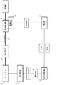
本発明による多目的車両の具体的な実施形態を説明する前に、図1を用いて、本発明による燃料カット制御の基本原理を説明する。ここでは、エンジン6からの動力は、ギヤ変速装置4によって変速され、駆動輪に伝達される。ギヤ変速装置4は複数の変速段を有し、1つの変速段から他の変速段にシフト動作によって切り替えられることによって変速が実現する。このシフト動作による変速段の連結状態、つまり変速咬合部材の噛み合いの状態は連結状態検出センサ80によって検出される。連結状態検出センサ80は、例えば、変速咬合部材や変速シフタ―の位置を検出する位置検出センサで構成することができる。連結状態検出センサ80の検出信号に基づいて、ギヤ変速装置4の連結状態を判定する判定部51が備えられている。判定部51は、ギヤ変速装置4が完全に連結している状態(例えば、変速咬合部材や変速シフタ―が連結位置に入っている状態)では完全連結状態を出力し、ギヤ変速装置4が完全に連結しておらず、動力を伝達していない状態(例えば、変速咬合部材や変速シフタ―が連結位置から外れている状態)では完全連結状態を、判定結果として出力する。
Before describing a specific embodiment of a multipurpose vehicle according to the present invention, the basic principle of fuel cut control according to the present invention will be described with reference to FIG. Here, the power from the engine 6 is shifted by the
エンジン6は燃料供給部60によって供給される燃料供給量によって回転数が調整される。燃料供給部60によって供給される燃料供給量は、燃料供給制御部50によって生成され、出力されるエンジン制御指令に基づいて、決定される。燃料供給制御部50は、エンジン回転数データやアクセル操作具などの操作量データなどに基づいて、エンジン制御指令を生成する。通常は、アクセル操作具等の操作量から、演算式やルックアップテーブルを用いて燃料供給量の基準値を導出し、その基準値からエンジン制御指令を生成して、燃料供給部60に与える。さらに、判定部51が、判定結果として不完全連結状態を出力している場合には、燃料供給量を基準量より低減させる燃料カットを行わせる燃料カット指令を燃料供給部60に与える。その低減量は、エンジン回転数がゼロになるかまたはほぼゼロになるよう、設定するのが好ましい。
The rotational speed of the engine 6 is adjusted by the amount of fuel supplied by the
なお、図1において、点線で示されているように、エンジン6とギヤ変速装置4の間の動力伝達経路20に遠心クラッチ2が設けられている場合には、燃料カット指令に基づく供給燃料の低減量は、遠心クラッチに伝達されるエンジン動力の回転数が遠心クラッチ2のクラッチイン回転数より低くなるように、設定することが好適である。これにより、ギヤ変速装置4の連結状態が不完全な場合、ギヤ変速装置4への入力回転数がゼロになるので、変速時のギヤ鳴りが回避される。
In FIG. 1, when the
ギヤ変速装置4の連結状態が完全となれば、判定部51が完全連結状態を出力するので、燃料供給制御部50は、基準通りの燃料供給を行うエンジン制御指令を燃料供給部60に与える。
When the connected state of the
次に、図面を用いて、本発明による多目的車両の具体的な実施形態の1つを説明する。
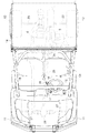
図2と図3に示される多目的車両は、荷の運搬やレクリエーション等の多様な目的に使用可能な車両として構成されている。多目的車両には、水冷式のガソリンエンジンで構成されているエンジン6と、エンジン6の駆動力に基づいて駆動される駆動輪を有する走行機体とが備えられている。この実施形態の多目的車両は、四輪駆動車であり、駆動可能且つ操向操作可能な左右一対の前車輪11と、駆動可能な左右一対の後車輪12とが駆動輪として機能する。走行機体の中央部には、操縦者が搭乗して運転操作を行う運転部13が備えられている。走行機体の後部には、荷を積載可能で、且つ、ダンプ操作可能な荷台14が備えられている。
Next, one specific embodiment of the multipurpose vehicle according to the present invention will be described with reference to the drawings.
The multipurpose vehicle shown in FIGS. 2 and 3 is configured as a vehicle that can be used for various purposes such as transporting goods and recreation. The multipurpose vehicle is provided with an engine 6 constituted by a water-cooled gasoline engine and a traveling machine body having driving wheels driven based on the driving force of the engine 6. The multi-purpose vehicle of this embodiment is a four-wheel drive vehicle, and a pair of left and right
運転部13には、前車輪11の操向操作用のステアリングハンドル15、走行速度を変更するための人為操作可能なアクセル操作具としてのアクセルペダル16、変速操作用の変速操作具としての変速レバー17、搭乗者が着座可能な座席18等が備えられている。変速レバー17は、揺動操作により、前進一速位置、前進二速位置、中立位置、後進位置に切り換え可能に構成されている。
The
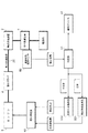
図3に示されるように、エンジン6からの動力を伝達する動力伝達経路20には、ベルト式無段変速装置3、高速変速段と低速変速段と後進変速段とを有するギヤ変速装置4、後輪差動機構22、左右一対の後車軸23、動力取出軸24、推進軸25、前輪差動機構26、左右一対の前車軸27等が備えられている。後輪差動機構22は、走行機体の旋回に連動して、左右の後車軸23の回転速度を調節する。前輪差動機構26は、走行機体の旋回に連動して、左右の前車軸27の回転速度を調節する。
As shown in FIG. 3, the
図3に示されるように、動力伝達経路20におけるエンジン6とベルト式無段変速装置3との間には、遠心クラッチ2が備えられている。この実施形態では、遠心クラッチ2はベルト式無段変速装置3の入力軸でもあるエンジン6の出力軸34に設けられている。これにより、エンジン6の出力軸34の回転数(ここでの回転数は時間当たりの回転数、つまりエンジン6の回転速度を意味している)がクラッチイン回転数の場合は、遠心クラッチ2が切状態となり、ベルト式無段変速装置3及びギヤ変速装置4へ動力が伝達されない状態となる。一方、エンジン6の出力軸34の回転数がクラッチイン回転数以上になれば、遠心クラッチ2が入状態となり、ベルト式無段変速装置3及びギヤ変速装置4へ動力が伝達される状態となる。
As shown in FIG. 3, the
図3に示されるように、ベルト式無段変速装置3の出力は、ギヤ変速装置4に伝達される。ギヤ変速装置4は、ギヤ変速装置4は、ベルト式無段変速装置3からの動力を変速して、駆動輪(前車輪11及び後車輪12)に供給する。
As shown in FIG. 3, the output of the belt type continuously
図3に示されるギヤ変速装置4の変速状態は、前進一速状態、前進二速状態、中立状態、後進状態に切り換え可能となっている。前進一速状態、前進二速状態、後進状態とは、それぞれ、互いに変速比が異なる。
The shift state of the
変速レバー17を前進一速位置にすると、ギヤ変速装置4が前進一速変速段となる。変速レバー17を前進二速位置にすると、ギヤ変速装置4が前進二速変速段となる。変速レバー17を中立位置にすると、ギヤ変速装置4が中立状態になる。変速レバーを後進位置にすると、ギヤ変速装置4が後進変速段となる。この実施形態では、変速レバー17の操作変位に基づいてシフト動作して上述した変速段を作り出す第1シフタ41と第2シフタ42とが備えられている。さらに、この実施形態では、第1シフタ41の位置を検出する第1シフタ位置検出センサ81と、第2シフタ42の位置を検出する第2シフタ位置検出センサ82が、第1シフタ41と第2シフタ42との連結状態を検出する連結状態検出センサ80として備えられている。
When the
図3に示されるように、ギヤ変速装置4からの出力は、後輪差動機構22を介して、左右の後車軸23に伝達され、左右の後車輪12が回転駆動される。そして、ギヤ変速装置4から出力された駆動力は、動力取出軸24、推進軸25、前輪差動機構26を介して、左右の前車軸27に伝達され、左右の前車輪11が回転駆動される。動力取出軸24と推進軸25との間、及び、推進軸25と前輪差動機構26との間は、それぞれ、ユニバーサルジョイントにより連動連結されている。動力取出軸24には、クラッチ装置28が備えられている。クラッチ装置28を入状態にすると、動力取出軸24の伝動上手側部分と伝動下手側部分とが連動連結され、前車輪11側へ動力が伝達される状態(四輪駆動状態)となる。一方、クラッチ装置28を切状態にすると、動力取出軸24の伝動上手側部分と伝動下手側部分との連動連結が解除されて、動力取出軸24から前車輪11側へ動力が伝達されない状態(二輪駆動状態)となる。
As shown in FIG. 3, the output from the
図4に、この多目的車両の制御装置5における燃料供給制御系の機能ブロック図が示されている。制御装置5は、燃料供給制御部50、判定部51、入力信号処理部52、出力信号処理部53を備えている。入力信号処理部52は、ギヤ変速装置4の連結状態を検出する連結状態検出センサ80(図5参照)からの検出信号や、アクセルペダル16やブレーキペダルなどの操作変位を検出するセンサなどからなる車両状態検出センサ群8からの検出信号を入力し、必要な前処理を施して、制御装置5の機能部に転送する。出力信号処理部53は、エンジン6へ燃料を供給する燃料供給部60や報知デバイス91と接続している。出力信号処理部53は、燃料供給部60には、燃料供給制御部によって生成された燃料供給に関する制御指令を送り、運転者に報知すべき情報を視覚的あるいは聴覚的な方法で運転者に報知する報知デバイス91には、適切な報知信号を送る。
FIG. 4 is a functional block diagram of a fuel supply control system in the multipurpose vehicle control device 5. The control device 5 includes a fuel
燃料供給制御部50は、燃料供給量算定部501と燃料カット指令部502とを備えている。判定部51及び燃料カット指令部502は、実質的には、図1を用いて説明した基本原理に基づいて動作する。判定部51は、連結状態検出センサ80からの検出信号に基づいて、ギヤ変速装置4が不完全連結状態(シフトギヤの未咬合状態)であるか、または不完全連結状態であるかを判定し、その判定結果を燃料供給制御部50に与える。同時に、その判定結果を運転者に報知するため、出力信号処理部53を介して、報知デバイス91に報知信号を与え、ギヤ変速装置4が不完全連結状態であるか、または不完全連結状態であるかが判別できる形態で動作させる。
The fuel
燃料供給制御部50は、燃料供給量算定部501と燃料カット指令部502とを備えている。燃料供給量算定部501は、アクセルペダル16などのアクセル操作具の操作量に基づいて、エンジン6に供給する燃料供給量を算定する。判定部51によって完全連結状態(ギヤ変速装置4を介して動力が伝達されている状態)が判定された場合には、燃料供給制御部50は、燃料供給量算定部501によって算定された燃料供給量での燃料供給指令を燃料供給部60に与え、判定部51によって不完全連結状態が判定された場合には、燃料の供給量を燃料供給量算定部501によって算定される基準値より低減させる燃料カットを実行する燃料カット指令を燃料供給部60に与える。燃料カットによる燃料低減量は調整可能であり、燃料供給量をゼロにすることも可能である。この実施形態では、燃料カット指令によって実行される燃料供給量は、遠心クラッチ2へ入力される動力の回転数が遠心クラッチのクラッチイン回転数より小さくなるように設定されている。したがって、ギヤ変速装置4の不完全連結状態では、アクセルペダル16を踏み込んでも、エンジン回転数は上昇せず、遠心クラッチからギヤ変速装置4への動力伝達は遮断される。
The fuel
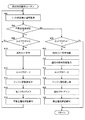
次に図5と図6とを用いて、燃料カット制御の流れ一例を説明する。図6の燃料カット制御ルーチンでは、エンジン6が燃料カット状態である場合、カットフラグに「1」が入り、エンジン6が基準の燃料供給量を受けている状態である場合、カットフラグに「0」が入る。制御初期処理においてカットフラグは「0」に設定される。 Next, an example of the flow of fuel cut control will be described with reference to FIGS. In the fuel cut control routine of FIG. 6, when the engine 6 is in the fuel cut state, “1” is set in the cut flag, and when the engine 6 is receiving the reference fuel supply amount, “0” is set in the cut flag. Is entered. In the control initial process, the cut flag is set to “0”.
図6に示された燃料カット制御ルーチンに入ると、まず、判定部51が連結状態検出センサ80から検出信号を取得する(#02)。検出信号に基づいて判定部51は、検出信号から、ギヤ変速装置4の連結状態(咬合状態)が完全(ギヤが完全に入っている)であるか、または不完全(ギヤが外れている)であるかを判定する。ギヤ変速装置4が不完全状態と判定された場合(#04)、さらに、カットフラグの値が「0」であるかどうかチェックされる(#06)。カットフラグの値が「0」であれば、ギヤ変速装置4が完全状態から不完全状態に移行した直後である見なされる。したがって(#06でYes分岐)、燃料カット処理が開始される。まず、燃料カット指令部502が燃料カット指令を燃料供給部60に送る(#10)。これにより、エンジン6が燃料カット状態となるので、燃料カット処理中であることを示すために、カットフラグに「1」が入る(#12)。燃料カットの結果、エンジン回転数が低下し(#14)、遠心クラーチ33の入力回転数が遠心クラッチ2のクラッチイン回転数より低くなることで、遠心クラッチ2による動力伝達は遮断される(#16)。さらに、ギヤ変速装置4の連結状態が不完全であること、つまりギヤが正確に入っていないことを運転者に報知するための制御信号を報知デバイス91に送る(#16)。
When the fuel cut control routine shown in FIG. 6 is entered, first, the
ステップ#06のチェックで、カットフラグの値が「1」であれば(#06でNo分岐)、つまり、不完全状態の判定が続行しており、燃料カット処理中であるので、そのまま、ステップ#02に戻って、再び検出信号を取得する。 If the value of the cut flag is “1” in the check of step # 06 (No branch at # 06), that is, the determination of the incomplete state is continuing and the fuel cut process is in progress. Returning to # 02, the detection signal is acquired again.
判定部51でギヤ変速装置4が完全状態と判定された場合、ステップ#04のチェックでNo分岐し(#04でYes分岐)、次いで、カットフラグの値がチェックされる(#08)。ここで、カットフラグの値が「1」になっておれば(#08でYes分岐)、ギヤ変速装置4の連結状態が、不完全連結状態から完全連結状態に移行したことになるので、燃料カット指令が解除され(#20)、燃料供給量算定部501によって算定された基準の燃料供給量を含む通常のエンジン制御指令が燃料供給部60に送られる(#21)。これにより、エンジン6が基準の燃料供給量を受けている通常燃料供給状態となるので、カットフラグに「0」が入る(#22)。通常燃料供給の結果、エンジン回転数が上昇し(#24)、遠心クラーチ33の入力回転数が遠心クラッチ2のクラッチイン回転数より高くなることで、遠心クラッチ2がクラッチインし、遠心クラッチ2による動力伝達が行われる(#26)。さらに、ギヤ変速装置4の連結状態が完全であること、つまりギヤが正確に入っていることを運転者に報知するための制御信号を報知デバイス91に送る(#28)。
When the
ステップ#08のチェックで、カットフラグの値が「0」であれば(#08でNo分岐)、ギヤ変速装置4の完全な連結状態であることを意味するので、一旦、このルーチンを抜け、所定のタイミングで、再度このルーチンに入る。もちろん、キースイッチがオフになるまで、このルーチンを抜け出すことなく、繰り返してもよい。
If it is determined in
〔別実施の形態〕
(1)上述した実施形態では、エンジン6とギヤ変速装置4との間の動力伝達経路20に遠心クラッチ2とベルト式無段変速装置3が介装されていたが、これらは必須ではない。遠心クラッチ2が存在しない場合、燃料カットによって燃料供給をゼロに低減し、エンジン6の回転数をゼロにするとよい。
(2)上述した実施形態では、進一速変速段と前進二速変速段と後進変速段とを有するギヤ変速装置4が例示されているが、これに限られない。例えば、前進一速変速段と前進二速変速段と後進変速段以外の異なる変速段、例えば、3つ以上の変速比の異なる前進変速段を有するギヤ変速装置4でもよいし、1つの前進変速段しかないギヤ変速装置4であってもよい。
(3)上述した実施形態では、連結状態検出センサ80は、変速咬合部材や変速シフタ―の位置を検出する位置検出センサで構成されていた。これに代えて、変速レバー17とギヤ変速装置4とを連結する操作変位連結リンクシステムを構成する、ギヤ変速装置4の完全連結状態と不完全連結状態との移行に対応する変位を行う変位部材の変位量を検出するセンサを用いてもよい。
(4)上記実施形態では、無段変速装置として、入力回転速度に応じて出力回転速度の無段変速を行うベルト式無段変速装置3が例示されているが、これに限られない。例えば、静油圧式変速装置を用いてもよい。
[Another embodiment]
(1) In the embodiment described above, the
(2) In the above-described embodiment, the
(3) In the above-described embodiment, the connection
(4) In the above-described embodiment, the belt-type continuously
本発明は、エンジンを駆動源として、ギヤ変速装置4が備えられている多目的車両に適用できる。
The present invention can be applied to a multi-purpose vehicle equipped with a
2 :遠心クラッチ
3 :ベルト式無段変速装置
4 :ギヤ変速装置
5 :制御装置
6 :エンジン
8 :車両状態検出センサ群
11 :前車輪
12 :後車輪
13 :運転部
14 :荷台
15 :ステアリングハンドル
16 :アクセルペダル
17 :変速レバー
18 :座席
20 :動力伝達経路
22 :後輪差動機構
23 :後車軸
24 :動力取出軸
25 :推進軸
26 :前輪差動機構
27 :前車軸
28 :クラッチ装置
33 :遠心クラーチ
34 :出力軸
41 :第1シフタ
42 :第2シフタ
50 :燃料供給制御部
51 :判定部
52 :入力信号処理部
53 :出力信号処理部
60 :燃料供給部
80 :連結状態検出センサ
81 :第1シフタ位置検出センサ
82 :第2シフタ位置検出センサ
91 :報知デバイス
501 :燃料供給量算定部
502 :燃料カット指令部
N :中立位置
2: Centrifugal clutch 3: Belt type continuously variable transmission 4: Gear transmission 5: Control device 6: Engine 8: Vehicle state detection sensor group 11: Front wheel 12: Rear wheel 13: Driving unit 14: Loading platform 15: Steering handle 16: Accelerator pedal 17: Shift lever 18: Seat 20: Power transmission path 22: Rear wheel differential mechanism 23: Rear axle 24: Power take-off shaft 25: Propulsion shaft 26: Front wheel differential mechanism 27: Front axle 28: Clutch device 33: Centrifugal clarch 34: Output shaft 41: First shifter 42: Second shifter 50: Fuel supply control unit 51: Determination unit 52: Input signal processing unit 53: Output signal processing unit 60: Fuel supply unit 80: Connection state detection Sensor 81: First shifter position detection sensor 82: Second shifter position detection sensor 91: Notification device 501: Fuel supply amount calculation unit 502: Fuel cut finger Headquarters N: Neutral position
Claims (4)
前記エンジンへ燃料を供給する燃料供給部と、
前記エンジンからの動力をシフト動作によって変速するギヤ変速装置と、
前記ギヤ変速装置の連結状態を検出する連結状態検出センサと、
前記連結状態検出センサからの検出信号に基づいて不完全連結状態を判定する判定部と、
前記判定部によって前記不完全連結状態が判定された場合に、前記燃料の供給量を基準値より低減させる燃料カットを実行する燃料供給制御部と、
を備えた多目的車両。 Engine,
A fuel supply section for supplying fuel to the engine;
A gear transmission that shifts power from the engine by a shift operation;
A connection state detection sensor for detecting a connection state of the gear transmission;
A determination unit that determines an incompletely connected state based on a detection signal from the connected state detection sensor;
A fuel supply control unit that executes a fuel cut that reduces the fuel supply amount from a reference value when the incompletely connected state is determined by the determination unit;
Multipurpose vehicle equipped with.
Priority Applications (2)
| Application Number | Priority Date | Filing Date | Title |
|---|---|---|---|
| JP2016041387A JP6624974B2 (en) | 2016-03-03 | 2016-03-03 | Multipurpose vehicle |
| US15/354,094 US10030595B2 (en) | 2016-03-03 | 2016-11-17 | Multipurpose vehicle |
Applications Claiming Priority (1)
| Application Number | Priority Date | Filing Date | Title |
|---|---|---|---|
| JP2016041387A JP6624974B2 (en) | 2016-03-03 | 2016-03-03 | Multipurpose vehicle |
Publications (2)
| Publication Number | Publication Date |
|---|---|
| JP2017155698A true JP2017155698A (en) | 2017-09-07 |
| JP6624974B2 JP6624974B2 (en) | 2019-12-25 |
Family
ID=59722121
Family Applications (1)
| Application Number | Title | Priority Date | Filing Date |
|---|---|---|---|
| JP2016041387A Expired - Fee Related JP6624974B2 (en) | 2016-03-03 | 2016-03-03 | Multipurpose vehicle |
Country Status (2)
| Country | Link |
|---|---|
| US (1) | US10030595B2 (en) |
| JP (1) | JP6624974B2 (en) |
Cited By (3)
| Publication number | Priority date | Publication date | Assignee | Title |
|---|---|---|---|---|
| JP2022105236A (en) * | 2020-12-31 | 2022-07-13 | 株式会社クボタ | Vehicle with engine |
| US11724586B2 (en) | 2020-10-05 | 2023-08-15 | Kubota Corporation | Work vehicle |
| JP2023154952A (en) * | 2022-04-08 | 2023-10-20 | 株式会社クボタ | Traveling vehicle |
Citations (6)
| Publication number | Priority date | Publication date | Assignee | Title |
|---|---|---|---|---|
| JPH01115735A (en) * | 1987-10-30 | 1989-05-09 | Diesel Kiki Co Ltd | Vehicle driving control device |
| JPH0267438A (en) * | 1988-08-31 | 1990-03-07 | Toyota Motor Corp | Fuel injection amount control device for internal combustion engines |
| JPH02201049A (en) * | 1989-01-31 | 1990-08-09 | Suzuki Motor Co Ltd | Acceleration control device of internal combustion engine |
| JPH10281279A (en) * | 1997-04-02 | 1998-10-23 | Denso Corp | Control device for internal combustion engine |
| JP2008196416A (en) * | 2007-02-14 | 2008-08-28 | Kawasaki Heavy Ind Ltd | Rough terrain vehicle |
| JP2012051507A (en) * | 2010-09-02 | 2012-03-15 | Kubota Corp | Working vehicle |
Family Cites Families (6)
| Publication number | Priority date | Publication date | Assignee | Title |
|---|---|---|---|---|
| IT1285045B1 (en) * | 1996-03-29 | 1998-06-03 | Magneti Marelli Spa | DEVICE AND METHOD OF TRANSMISSION CONTROL |
| JP4297286B2 (en) * | 2006-01-26 | 2009-07-15 | ジヤトコ株式会社 | Control device for automatic transmission |
| JP4483871B2 (en) * | 2007-02-05 | 2010-06-16 | トヨタ自動車株式会社 | Power transmission device control device and control method thereof |
| US9032824B2 (en) * | 2010-12-15 | 2015-05-19 | Yamaha Hatsudoki Kabushiki Kaisha | Control device for dual clutch transmission and control method for dual clutch transmission |
| JP5618105B2 (en) * | 2013-01-09 | 2014-11-05 | 三菱自動車工業株式会社 | Control device for hybrid vehicle |
| JP6263332B2 (en) * | 2013-03-05 | 2018-01-17 | 本田技研工業株式会社 | Shift control device |
-
2016
- 2016-03-03 JP JP2016041387A patent/JP6624974B2/en not_active Expired - Fee Related
- 2016-11-17 US US15/354,094 patent/US10030595B2/en active Active
Patent Citations (6)
| Publication number | Priority date | Publication date | Assignee | Title |
|---|---|---|---|---|
| JPH01115735A (en) * | 1987-10-30 | 1989-05-09 | Diesel Kiki Co Ltd | Vehicle driving control device |
| JPH0267438A (en) * | 1988-08-31 | 1990-03-07 | Toyota Motor Corp | Fuel injection amount control device for internal combustion engines |
| JPH02201049A (en) * | 1989-01-31 | 1990-08-09 | Suzuki Motor Co Ltd | Acceleration control device of internal combustion engine |
| JPH10281279A (en) * | 1997-04-02 | 1998-10-23 | Denso Corp | Control device for internal combustion engine |
| JP2008196416A (en) * | 2007-02-14 | 2008-08-28 | Kawasaki Heavy Ind Ltd | Rough terrain vehicle |
| JP2012051507A (en) * | 2010-09-02 | 2012-03-15 | Kubota Corp | Working vehicle |
Cited By (6)
| Publication number | Priority date | Publication date | Assignee | Title |
|---|---|---|---|---|
| US11724586B2 (en) | 2020-10-05 | 2023-08-15 | Kubota Corporation | Work vehicle |
| JP2022105236A (en) * | 2020-12-31 | 2022-07-13 | 株式会社クボタ | Vehicle with engine |
| JP7385553B2 (en) | 2020-12-31 | 2023-11-22 | 株式会社クボタ | Vehicle with engine |
| US11873769B2 (en) | 2020-12-31 | 2024-01-16 | Kubota Corporation | Engine-equipped vehicle |
| JP2023154952A (en) * | 2022-04-08 | 2023-10-20 | 株式会社クボタ | Traveling vehicle |
| JP7728225B2 (en) | 2022-04-08 | 2025-08-22 | 株式会社クボタ | Vehicles in motion |
Also Published As
| Publication number | Publication date |
|---|---|
| US10030595B2 (en) | 2018-07-24 |
| US20170254280A1 (en) | 2017-09-07 |
| JP6624974B2 (en) | 2019-12-25 |
Similar Documents
| Publication | Publication Date | Title |
|---|---|---|
| KR101959424B1 (en) | Control device for four-wheel-drive vehicle and control method for four-wheel drive vehicle | |
| US20210253162A1 (en) | Vehicle dig lock system | |
| CN106573661A (en) | Saddled vehicle | |
| US10323694B2 (en) | Work vehicle | |
| JP5146496B2 (en) | Four-wheel drive vehicle control system | |
| JP6624974B2 (en) | Multipurpose vehicle | |
| JP2014168999A (en) | Four-wheel drive vehicle | |
| JP2007218269A (en) | Control method of transmission for motorcycle | |
| JP7447843B2 (en) | Vehicles and vehicle control devices | |
| JP2004218687A (en) | Brake control mechanism | |
| JP2006298064A (en) | Vehicle creep control device | |
| JP2007269072A (en) | Work vehicle | |
| US11767017B2 (en) | Travel mode switching device for vehicle and display unit of the same | |
| JP2017155699A (en) | Multipurpose vehicle | |
| JP2009063083A (en) | Work vehicle | |
| JP7527861B2 (en) | Work vehicles | |
| JP7549302B2 (en) | Drive control device for four-wheel drive vehicle | |
| JP2005042814A (en) | Automatic driving-force connecting and disconnecting device | |
| JP7728225B2 (en) | Vehicles in motion | |
| JP2015101163A (en) | Work vehicle | |
| JP5280220B2 (en) | Control device for work vehicle | |
| JP2004076873A (en) | Automatic transmission control device for powered vehicles | |
| JP2008100546A (en) | Control device for four-wheel drive vehicle | |
| JP2622107B2 (en) | Front wheel drive control device for four-wheel drive agricultural tractor | |
| JP7159122B2 (en) | work vehicle |
Legal Events
| Date | Code | Title | Description |
|---|---|---|---|
| A621 | Written request for application examination |
Free format text: JAPANESE INTERMEDIATE CODE: A621 Effective date: 20180626 |
|
| A711 | Notification of change in applicant |
Free format text: JAPANESE INTERMEDIATE CODE: A711 Effective date: 20180706 |
|
| A131 | Notification of reasons for refusal |
Free format text: JAPANESE INTERMEDIATE CODE: A131 Effective date: 20190326 |
|
| A977 | Report on retrieval |
Free format text: JAPANESE INTERMEDIATE CODE: A971007 Effective date: 20190328 |
|
| A521 | Request for written amendment filed |
Free format text: JAPANESE INTERMEDIATE CODE: A523 Effective date: 20190523 |
|
| A02 | Decision of refusal |
Free format text: JAPANESE INTERMEDIATE CODE: A02 Effective date: 20190611 |
|
| A521 | Request for written amendment filed |
Free format text: JAPANESE INTERMEDIATE CODE: A523 Effective date: 20190911 |
|
| A521 | Request for written amendment filed |
Free format text: JAPANESE INTERMEDIATE CODE: A821 Effective date: 20190912 |
|
| A911 | Transfer to examiner for re-examination before appeal (zenchi) |
Free format text: JAPANESE INTERMEDIATE CODE: A911 Effective date: 20191007 |
|
| TRDD | Decision of grant or rejection written | ||
| A01 | Written decision to grant a patent or to grant a registration (utility model) |
Free format text: JAPANESE INTERMEDIATE CODE: A01 Effective date: 20191029 |
|
| A61 | First payment of annual fees (during grant procedure) |
Free format text: JAPANESE INTERMEDIATE CODE: A61 Effective date: 20191126 |
|
| R150 | Certificate of patent or registration of utility model |
Ref document number: 6624974 Country of ref document: JP Free format text: JAPANESE INTERMEDIATE CODE: R150 |
|
| LAPS | Cancellation because of no payment of annual fees |