JP2017156251A - Topographic change point extraction system and topographic change point extraction method - Google Patents
Topographic change point extraction system and topographic change point extraction method Download PDFInfo
- Publication number
- JP2017156251A JP2017156251A JP2016040510A JP2016040510A JP2017156251A JP 2017156251 A JP2017156251 A JP 2017156251A JP 2016040510 A JP2016040510 A JP 2016040510A JP 2016040510 A JP2016040510 A JP 2016040510A JP 2017156251 A JP2017156251 A JP 2017156251A
- Authority
- JP
- Japan
- Prior art keywords
- terrain
- change point
- inclination
- point
- terrain change
- Prior art date
- Legal status (The legal status is an assumption and is not a legal conclusion. Google has not performed a legal analysis and makes no representation as to the accuracy of the status listed.)
- Granted
Links
Images


Landscapes
- Instructional Devices (AREA)
Abstract
【課題】本願発明の課題は、従来が抱える問題を解決することであり、すなわち技術者によるばらつきを回避し、つまり客観的な判断によって地形変化点(地形変化線)を抽出することができる地形変化点抽出システム、及び地形変化点抽出方法を提供することである。
【解決手段】本願発明の地形変化点抽出システムは、地形モデルを用いて地形の変化点を抽出するシステムであり、地形量算出手段と、サンプル領域抽出手段、散布図作成手段、地形変化条件設定手段、地形変化点選別手段を備えたものである。散布図作成手段は、サンプル領域内にある単位区画の平均傾斜量と傾斜標準偏差を、平均傾斜量軸及び傾斜標準偏差軸からなる2軸平面に配置して散布図を作成する。地形変化点選別手段は、平均傾斜量と傾斜標準偏差の組み合わせが上限閾値線と下限閾値線の間となる単位区画を、地形変化点として選別する。
【選択図】図3An object of the present invention is to solve a problem of the prior art, that is, a terrain that can avoid variability by an engineer, that is, can extract a terrain change point (terrain change line) by objective judgment. A change point extraction system and a landform change point extraction method are provided.
A terrain change point extraction system according to the present invention is a system that extracts a terrain change point using a terrain model, and includes a terrain amount calculation means, a sample area extraction means, a scatter diagram creation means, and a terrain change condition setting. Means and terrain change point selection means. The scatter diagram creation means creates a scatter diagram by arranging the average inclination amount and inclination standard deviation of the unit sections in the sample area on a biaxial plane composed of an average inclination amount axis and an inclination standard deviation axis. The terrain change point selection means selects, as the terrain change point, a unit block in which the combination of the average inclination amount and the inclination standard deviation is between the upper threshold line and the lower threshold line.
[Selection] Figure 3
Description
本願発明は、地形モデルを用いて地形の変化点を抽出する技術に関するものであり、より具体的には、地形モデルを構成する単位区画ごとに平均傾斜量と傾斜量の標準偏差(以下、「傾斜標準偏差」という。)を求め、その平均傾斜量と傾斜標準偏差をもとに地形変化点を選別するシステムと方法に関するものである。 The present invention relates to a technique for extracting a change point of a terrain using a terrain model, and more specifically, an average inclination amount and a standard deviation of an inclination amount (hereinafter, “ It is related to a system and method for determining a terrain change point based on the average inclination amount and the inclination standard deviation.
我が国は、国土に占める山地の割合が多く、しかも雨が多いことから、地すべりや斜面崩壊といった斜面災害による被害を受けやすい。特に、ひとたび地すべりや深層崩壊が生ずると、甚大な被害を伴うこともある。このような斜面災害による被害を受けないように(あるいは軽減するように)、これまで原因となる斜面で対策工が施され、災害時における避難計画が策定されてきた。 Japan is prone to damage from slope disasters such as landslides and slope failures because of the large percentage of mountainous land in the country and heavy rain. In particular, once a landslide or deep landslide occurs, it can be extremely damaging. In order to prevent (or reduce) damage caused by such slope disasters, countermeasures have been implemented on the slopes that have caused the disaster, and evacuation plans have been formulated in the event of a disaster.
ところで、斜面対策工を行うにしても、住民の避難計画を策定するにしても、災害原因となる斜面を特定する必要がある。従来、地すべりが生じそうな地形(以下、「地すべり地形」という。)や、斜面崩壊が生じそうな地形(以下、「崩壊地形」という。)は、専門技術を有する技術者によって抽出されてきた。その際、膨大な範囲の地形から直ちに地すべり地形や崩壊地形を特定することは難しく、まずは地形的な特徴を糸口として候補となる地形を挙げ、その候補地形を詳細に検討することで地すべり地形や崩壊地形を抽出するのが一般的であった。 By the way, it is necessary to identify a slope that causes a disaster, whether it is a slope countermeasure work or a refuge plan for residents. Conventionally, terrain where landslides are likely to occur (hereinafter referred to as “landslide terrain”) and terrain where slope failures are likely to occur (hereinafter referred to as “collapsed terrain”) have been extracted by engineers having specialized skills. . At that time, it is difficult to immediately identify landslide or collapse terrain from a huge range of terrain. First, list the candidate terrain using the topographic features as clues, and examine the candidate terrain in detail to understand the landslide terrain and It was common to extract the collapsed terrain.
地すべり地形や崩壊地形の候補を挙げるためには、斜面勾配が急激に変化する地形に着目するのが有効であり、このような地形としては、斜面上方から見て緩斜面から急斜面に変化する「遷急線」と、急斜面から緩斜面に変化する「遷緩線」が知られている。またある断面に着目し、その断面のうち遷急線を構成する点を「遷急点」、遷緩線を構成する点を「遷緩点」と呼ぶこともある。なおここでは、遷急線と遷緩線の総称を「地形変化線」ということとし、遷急点と遷緩点の総称を「地形変化点」ということとする。 In order to list candidates for landslide topography and collapse topography, it is effective to focus on topography where the slope slope changes suddenly, and such topography changes from a gentle slope to a steep slope when viewed from above the slope. The “Transit Line” and the “Relax Line” that changes from a steep slope to a gentle slope are known. Moreover, paying attention to a certain cross section, a point constituting the transition line in the cross section may be referred to as a “transition point”, and a point constituting the transition line may be referred to as a “transition point”. In addition, here, the generic name of the rapid line and the gentle line is referred to as “terrain change line”, and the generic term of the rapid point and the gentle point is referred to as “terrain change point”.
地すべり地形や崩壊地形と同様、地形変化線や地形変化点もまた専門技術者によってこれまで抽出されてきた。専門技術者が有する知識とともに過去の経験にしたがって地形変化線等を抽出するわけであるが、そのため技術者によってその結果はそれぞれ異なることもあり、つまり技術者によって地形変化線等の適否判断が分かれていた。既述のとおり地形変化線等の抽出は、地すべり地形等の候補地形を挙げるために行うものであり、地形変化線等の抽出漏れはすなわち地すべり地形等の抽出漏れを意味する。 Like landslides and collapsed terrain, topographic change lines and topographic change points have also been extracted by experts. The topographic change lines are extracted according to the past experience together with the knowledge possessed by the specialists, but the results may differ from engineer to engineer. It was. As described above, the extraction of the terrain change line or the like is performed in order to list candidate terrain such as the landslide terrain, and the extraction failure of the terrain change line or the like means the extraction failure of the landslide topography or the like.
このような人為的なばらつきを回避するため、言い換えれば客観的な結果を得る目的で、機械的に地形の特徴を抽出する取り組みはこれまでも行われてきた。特許文献1では、地形図に地すべりブロック(平面形状)を与えることで、その地すべり方向を自動的に求める技術について提案している。 In order to avoid such an artificial variation, in other words, for the purpose of obtaining an objective result, efforts have been made to extract features of the terrain mechanically. Patent Document 1 proposes a technique for automatically obtaining a landslide direction by giving a landslide block (planar shape) to a topographic map.
ところが特許文献1を含めこれまで、遷急線や遷緩線といった地形変化線(あるいは地形変化点)を機械的(自動的)に抽出する技術が提示されることはなく、関係者の間ではこのような技術が強く要望されるところであった。 However, up to now, including Patent Document 1, no technology has been proposed to extract the terrain change line (or terrain change point) such as a rapid line or a gradual line mechanically (automatically). There was a strong demand for such a technology.
本願発明の課題は、従来が抱える問題を解決することであり、すなわち技術者によるばらつきを回避し、つまり客観的な判断によって地形変化点(地形変化線)を抽出することができる地形変化点抽出システム、及び地形変化点抽出方法を提供することである。 The object of the present invention is to solve the problems of the prior art, that is, to avoid variability by engineers, that is, to extract terrain change points (terrain change lines) by objective judgment A system and a terrain change point extraction method are provided.
本願発明は、地形モデルを構成する単位区画ごとに求められる平均傾斜量と傾斜標準偏差に基づいて地形変化点を選別する、という点に着目したものであり、従来にはなかった発想に基づいてなされた発明である。 The present invention focuses on the point that the terrain change point is selected based on the average inclination amount and the inclination standard deviation obtained for each unit section constituting the terrain model. It is an invention made.
本願発明の地形変化点抽出システムは、地形モデルを用いて地形の変化点を抽出するシステムであり、地形量算出手段と、サンプル領域抽出手段、散布図作成手段、地形変化条件設定手段、地形変化点選別手段を備えたものである。ここで地形モデルとは、所定領域を平面分割して得られる多数の単位区画と、これら単位区画がそれぞれ具備する標高値を含んで構成されるものである。地形量算出手段は、単位区画に対して平均傾斜量と傾斜標準偏差を求めるもので、サンプル領域抽出手段は、オペレータの操作により所定領域のうち地形の特徴に着目してサンプル領域を抽出するものである。また散布図作成手段は、サンプル領域内にある単位区画の平均傾斜量と傾斜標準偏差を、平均傾斜量軸及び傾斜標準偏差軸からなる2軸平面に配置して散布図を作成するもので、地形変化条件設定手段は、散布図に基づいて閾値線を設定するとともにこの閾値線を基準として上限閾値線と下限閾値線を設定するものである。そして地形変化点選別手段は、平均傾斜量と傾斜標準偏差の組み合わせが上限閾値線と下限閾値線の間となる単位区画を、地形変化点として選別するものである。なお、平均傾斜量は、単位区画の周辺にある複数の単位区画の組み合わせによって算出される複数の周辺傾斜量に基づいて求められるもので、傾斜標準偏差は、複数の周辺傾斜量に基づいて求められるものである。 The terrain change point extraction system of the present invention is a system that extracts terrain change points using a terrain model, and includes a terrain amount calculation means, a sample area extraction means, a scatter diagram creation means, a terrain change condition setting means, a terrain change. A point selection means is provided. Here, the terrain model includes a large number of unit sections obtained by dividing a predetermined area into planes, and elevation values included in the unit sections. The terrain amount calculation means calculates the average inclination amount and the inclination standard deviation for the unit section, and the sample area extraction means extracts the sample area by paying attention to the terrain feature in the predetermined area by the operation of the operator. It is. The scatter diagram creation means creates a scatter diagram by arranging the average inclination amount and inclination standard deviation of the unit sections in the sample area on a two-axis plane composed of an average inclination amount axis and an inclination standard deviation axis. The terrain change condition setting means sets a threshold line based on a scatter diagram and sets an upper threshold line and a lower threshold line based on the threshold line. The terrain change point selection means selects, as the terrain change point, a unit block in which the combination of the average inclination amount and the inclination standard deviation is between the upper threshold line and the lower threshold line. The average inclination amount is obtained based on a plurality of peripheral inclination amounts calculated by a combination of a plurality of unit sections around the unit section, and the inclination standard deviation is obtained based on a plurality of peripheral inclination amounts. It is what
本願発明の地形変化点抽出システムは、回帰線を利用して閾値線を設定するものとすることもできる。この場合、地形変化条件設定手段は、散布図に配置された平均傾斜量と傾斜標準偏差の関係を代表する回帰線を求め、この回帰線を閾値線として設定する。 The topographic change point extraction system of the present invention can set a threshold line using a regression line. In this case, the terrain change condition setting means obtains a regression line representing the relationship between the average slope amount and the slope standard deviation arranged in the scatter diagram, and sets the regression line as a threshold line.
本願発明の地形変化点抽出システムは、複数の地形変化点を繋ぐことで地形変化線を生成する地形変化線生成手段を、さらに備えたものとすることもできる。 The terrain change point extraction system of the present invention may further include terrain change line generation means for generating a terrain change line by connecting a plurality of terrain change points.
本願発明の地形変化点抽出システムは、地形変化点選別手段によって選別された地形変化点に対してその適正を判定する適正判定手段を、さらに備えたものとすることもできる。適正判定手段は、適正判定する地形変化点を注目地形変化点として認識するとともに、この注目地形変化点の周辺にある複数の単位区画のうち、地形変化点として選別された単位区画の数に基づいて注目地形変化点としての適正を判定するものである。 The terrain change point extraction system of the present invention may further include appropriate determination means for determining the appropriateness of the terrain change points selected by the terrain change point selection means. The appropriateness determination means recognizes the landform change point to be determined as appropriate as the target landform change point, and based on the number of unit sections selected as the landform change point among the plurality of unit sections around the target landform change point. Thus, the appropriateness as the noticeable terrain change point is determined.
本願発明の地形変化点抽出システムは、地形変化点の傾斜方向を設定する傾斜方向設定手段と、地形変化点に対して遷緩点又は遷急点のいずれかに選別する緩急選別手段を、さらに備えたものとすることもできる。傾斜方向設定手段は、傾斜方向を設定しようとする地形変化点を注目地形変化点として認識するとともに、この注目地形変化点の周辺にある複数の単位区画のうち、最も標高値が小さい単位区画を傾斜方向点として抽出し、この傾斜方向点に向かう方向を注目地形変化点の傾斜方向として設定するものである。緩急選別手段は、注目地形変化点の平均傾斜量が、傾斜方向点の平均傾斜量より大きいときにその注目地形変化点を遷緩点として選別し、注目地形変化点の平均傾斜量が、傾斜方向点の平均傾斜量より小さいときにその注目地形変化点を遷急点として選別するものである。 The terrain change point extraction system of the present invention further includes an inclination direction setting means for setting an inclination direction of the terrain change point, and a slow / fast selection means for selecting either a transition point or a transition point with respect to the terrain change point, It can also be provided. The inclination direction setting means recognizes the terrain change point for which the inclination direction is to be set as the target terrain change point, and selects the unit block having the smallest altitude value from among the plurality of unit sections around the target terrain change point. It is extracted as an inclination direction point, and the direction toward the inclination direction point is set as the inclination direction of the target landform change point. When the average slope of the target terrain change point is larger than the average slope amount of the direction point, the gradual selection means selects the target terrain change point as a transition point, and the average slope amount of the target terrain change point is the slope. When the average inclination amount of the direction point is smaller than that, the attentional landform change point is selected as a transition point.
本願発明の地形変化点抽出方法は、地形モデルを用いて地形の変化点を抽出する方法であり、地形量算出工程と、サンプル領域抽出工程、散布図作成工程、地形変化条件設定工程、地形変化点選別工程を備えたものである。地形量算出工程では、単位区画に対して平均傾斜量と傾斜標準偏差を求め、サンプル領域抽出工程では、所定領域のうち地形の特徴に着目したサンプル領域をオペレータが抽出する。また散布図作成工程では、サンプル領域内にある単位区画の平均傾斜量と傾斜標準偏差を平均傾斜量軸及び傾斜標準偏差軸からなる2軸平面に配置することで散布図を作成し、地形変化条件設定工程では、散布図に基づいて閾値線を設定するとともにこの閾値線を基準として上限閾値線と下限閾値線を設定する。そして地形変化点選別工程では、平均傾斜量と傾斜標準偏差の組み合わせが上限閾値線と下限閾値線の間となる単位区画を、地形変化点として選別する。なお、平均傾斜量は、単位区画の周辺にある複数の単位区画の組み合わせによって算出される複数の周辺傾斜量に基づいて求められるもので、傾斜標準偏差は、複数の周辺傾斜量に基づいて求められるものである。 The landform change point extraction method of the present invention is a method for extracting landform change points using a landform model, a landform amount calculation step, a sample area extraction step, a scatter diagram creation step, a landform change condition setting step, a landform change A point selection process is provided. In the terrain amount calculation step, the average inclination amount and the inclination standard deviation are obtained for the unit section, and in the sample region extraction step, the operator extracts a sample region focusing on the features of the terrain among the predetermined regions. In the scatter plot creation process, the average slope amount and slope standard deviation of the unit sections in the sample area are arranged on a two-axis plane consisting of the mean slope axis and slope standard deviation axis, creating a scatter chart and changing the topography In the condition setting step, a threshold line is set based on the scatter diagram, and an upper limit threshold line and a lower limit threshold line are set based on the threshold line. Then, in the topographic change point selection step, a unit block in which the combination of the average inclination amount and the standard inclination is between the upper threshold line and the lower threshold line is selected as the topographic change point. The average inclination amount is obtained based on a plurality of peripheral inclination amounts calculated by a combination of a plurality of unit sections around the unit section, and the inclination standard deviation is obtained based on a plurality of peripheral inclination amounts. It is what
本願発明の地形変化点抽出システム、及び地形変化点抽出方法には、次のような効果がある。
(1)技術者によるばらつきを回避し、客観的な判断によって地形変化点(地形変化線)を抽出することができる。その結果、地すべり地形や崩壊地形の抽出漏れを防ぐことができる。
(2)人による作業を大幅に省略できることから、作業コストを低減することができるとともに、地すべり地形等をこれまでより迅速に抽出することができる。
The landform change point extraction system and landform change point extraction method of the present invention have the following effects.
(1) Variations by engineers can be avoided, and terrain change points (terrain change lines) can be extracted by objective judgment. As a result, it is possible to prevent landslide topography and collapse topography from being extracted.
(2) Since work by humans can be largely omitted, the work cost can be reduced, and landslide topography and the like can be extracted more quickly than before.
本願発明の地形変化点抽出システム、及び地形変化点抽出方法の一例を、図を参照しながら説明する。 An example of the landform change point extraction system and landform change point extraction method of the present invention will be described with reference to the drawings.
1.全体概要
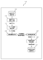
図1は、本願発明の地形変化点抽出システム100を示すブロック図である。この図に示すように地形変化点抽出システム100は、条件設定手段110と地形変化抽出手段120を含んで構成され、プリンタやディスプレイといった出力手段130を含むこともできる。条件設定手段110は、地形変化点を抽出するための条件(以下、「地形変化条件」という。)を設定するもので、この地形変化条件に基づいて地形変化抽出手段120が地形変化点を抽出する。なお本願発明の地形変化点抽出システム100は、プログラムを実行するコンピュータを利用して構成するとよい。以下、条件設定手段110と地形変化抽出手段120について詳しく説明する。
1. Overall Overview FIG. 1 is a block diagram showing a topographic change
2.条件設定手段
図2は、地形変化条件を設定するための主な処理(工程)を示すフロー図であり、図3は、条件設定手段110を示すブロック図である。なお、図2の中央の列には実施する処理(工程)を示しており、左列にはその処理(工程)に必要な入力情報を、右列にはその処理(工程)から生まれる出力情報を示している。以下、これらの図を参照しながら条件設定手段110について説明する。
2. Condition Setting Unit FIG. 2 is a flowchart showing main processes (steps) for setting the terrain change condition, and FIG. 3 is a block diagram showing the
(地形モデル)
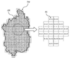
図4は、地形モデルと単位区画を説明するモデル図である。この図に示すように地形モデルTMは、所定領域ARを平面分割した網目状のモデルであり、単位区画BLは平面分割された結果得られる小領域のことである。言い換えれば、地形モデルTMは多数の単位区画BLによって構成される。例えば、図4左側の破線領域は、24個の単位区画BLで構成されていることが分かる。なお、この図にも示すように、それぞれの単位区画BLには識別番号(図ではBL323〜BL824)が付与されることが多い。また地形モデルTMは、平面座標(あるいは緯度経度)が付与されており、通常は単位区画BLの格子点に平面座標等が付与されている。
(Terrain model)
FIG. 4 is a model diagram for explaining the terrain model and the unit section. As shown in this figure, the terrain model TM is a mesh-like model obtained by dividing a predetermined area AR into planes, and the unit block BL is a small area obtained as a result of dividing into planes. In other words, the terrain model TM is composed of a large number of unit sections BL. For example, it can be seen that the broken line area on the left side of FIG. 4 is composed of 24 unit sections BL. In addition, as shown also in this figure, an identification number (BL323 to BL824 in the figure) is often given to each unit section BL. The topographic model TM is given plane coordinates (or latitude and longitude), and usually plane coordinates and the like are given to lattice points of the unit block BL.
このような地形モデルTMとして代表的なのが、DEM(Digital Elevation Model)やDSM(Digital Surface Model)である。地表モデルとも言われるDEMは、地形モデルTMを構成する個々の単位区画BLに標高値が付与され、一方表層モデルとも言われるDSMは、地形モデルTMを構成する個々の単位区画BLに、被覆物等の標高値が付与される。これら標高値は、単位区画BLのうち中心点や格子点に付与されるのが一般的である。なお図4では所定領域ARが略正方格子状に区切られ、単位区画BLの形状も略正方形となっているが、これに限らず、単位区画BLの形状を長方形やひし形、あるいは長円形など任意の形状とすることが可能で、さらにそれぞれの単位区画BLの形状や大きさを変えることもできる。 Typical examples of such a terrain model TM are DEM (Digital Elevation Model) and DSM (Digital Surface Model). The DEM, which is also referred to as the ground surface model, is given altitude values to the individual unit sections BL constituting the topographic model TM, while the DSM, also referred to as the surface layer model, is covered with the individual unit sections BL constituting the topographic model TM. Elevation values such as are given. These elevation values are generally assigned to the center point or grid point of the unit block BL. In FIG. 4, the predetermined area AR is divided into a substantially square lattice and the shape of the unit section BL is also substantially square. However, the shape of the unit section BL is not limited to this, but may be any shape such as a rectangle, a rhombus, or an oval. Further, the shape and size of each unit section BL can be changed.
地形モデルTMは、図3に示す地形モデル記憶手段111に記憶され、地形モデル読出し手段112によって読み出される(Step101:図2)。
The terrain model TM is stored in the terrain
(サンプル領域)
ここでサンプル領域とは、地形(特に勾配の変化)に特徴がある領域であり、操作者(オペレータ)によって選定される。サンプル領域としては、例えば、急斜面から比較的緩やかな堆積斜面に変化する地形に着目したり、山頂緩斜面からさらに緩斜面に変化する地形に着目したり、緩斜面から急斜面に変化する崖状の地形に着目して選定することができる。さらに、これらの特徴に加え、規模(面積)に応じて細分化してもよい。なおサンプル領域は、地形の変化点を抽出しようとする所定領域ARに対して1種類のみ抽出してもよいし、2種類以上を抽出してもよい。2種類以上のサンプル領域を抽出する場合、地形変化条件はサンプル領域の数だけ設定される。
(Sample area)
Here, the sample area is an area characterized by terrain (especially gradient change), and is selected by an operator (operator). Sample areas include, for example, terrain that changes from a steep slope to a relatively gentle slope, focussed on topography that changes from a gentle slope to a gentle slope, or a cliff-like shape that changes from a gentle slope to a steep slope. It can be selected by paying attention to the topography. Further, in addition to these features, the image may be subdivided according to the scale (area). It should be noted that only one type of sample area may be extracted for the predetermined area AR for which the change point of the terrain is to be extracted, or two or more types may be extracted. When extracting two or more types of sample areas, the terrain change condition is set by the number of sample areas.
サンプル領域は、図3に示すサンプル領域抽出手段113をオペレータが操作することで抽出される(Step102:図2)。具体的には、表示手段130に表示した地形モデルTMを確認しながら、オペレータがマウスなどポインティングデバイスを利用して所定の領域を指定するとよい。
The sample area is extracted by the operator operating the sample area extracting means 113 shown in FIG. 3 (Step 102: FIG. 2). Specifically, the operator may specify a predetermined area using a pointing device such as a mouse while checking the terrain model TM displayed on the
(平均傾斜量)
サンプル領域が抽出されると、そのサンプル領域内にある単位区画BLに対して平均傾斜量Iを求める。通常、サンプル領域内には複数の単位区画BLがあり、これらの単位区画BLに対してそれぞれ平均傾斜量Iを求める。平均傾斜量Iは、算出対象の単位区画BLの周辺にある複数の単位区画BLを用いて算出される。ここでは混乱を避けるため、平均傾斜量Iを求める対象となる単位区画BLを「対象単位区画BLa」と、対象単位区画BLaの周辺にある単位区画BLのうち平均傾斜量Iの算出に用いられる単位区画BLを「周辺単位区画BLs」ということとする。
(Average slope)
When the sample area is extracted, an average inclination amount I is obtained for the unit block BL in the sample area. Usually, there are a plurality of unit sections BL in the sample area, and an average inclination amount I is obtained for each of these unit sections BL. The average inclination amount I is calculated using a plurality of unit sections BL around the unit section BL to be calculated. Here, in order to avoid confusion, the unit partition BL for which the average inclination amount I is obtained is used as the “target unit partition BLa” and the average inclination amount I is calculated among the unit partitions BL around the target unit partition BLa. The unit section BL is referred to as “peripheral unit section BLs”.
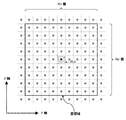
図5は、平均傾斜量Iの算出手法を説明するモデル図である。この図では、X軸とY軸からなる平面上に配置された地形モデルTMの一部を示しており、中央の網掛けされたものを対象単位区画BLaとし、その周辺にあるものを周辺単位区画BLsとしている。 FIG. 5 is a model diagram for explaining a method of calculating the average inclination amount I. In this figure, a part of the terrain model TM arranged on the plane composed of the X axis and the Y axis is shown, and the shaded portion at the center is the target unit section BLa, and the surrounding portions are the peripheral units. It is set as a section BLs.
対象単位区画BLaの平均傾斜量Iを算出するに当たって、まず周辺単位区画BLsの範囲(以下、「窓領域」という。)を設定する(Step103:図2)。例えば図5では、対象単位区画BLaを中心に9(Nx)×9(Ny)を窓領域とし、計80個の周辺単位区画BLsが設定されている。なお窓領域は、あらかじめ定められた範囲(Nx×Ny)に基づいて自動生成することもできるし、その都度範囲(Nx×Ny)を入力し、その範囲に基づいて設定することもできる。 In calculating the average inclination amount I of the target unit section BLa, first, the range of the peripheral unit section BLs (hereinafter referred to as “window region”) is set (Step 103: FIG. 2). For example, in FIG. 5, 9 (Nx) × 9 (Ny) is set as the window area centering on the target unit section BLa, and a total of 80 peripheral unit sections BLs are set. Note that the window region can be automatically generated based on a predetermined range (Nx × Ny), or can be set based on the range (Nx × Ny) input each time.
窓領域が設定できると、周辺単位区画BLsを用いて「周辺傾斜量」が算出される。具体的には、隣接する2つの周辺単位区画BLsを用い、その標高値の差を距離で除したものが周辺傾斜量として算出される。このとき、X軸方向に隣接する周辺単位区画BLsの組み合わせ、Y軸方向に隣接する周辺単位区画BLsの組み合わせ、その両方で算出され、図5の場合であれば8×9×2通りの組み合わせで周辺傾斜量が算出される。 When the window area can be set, the “peripheral inclination amount” is calculated using the peripheral unit section BLs. Specifically, two neighboring unit sections BLs that are adjacent to each other and the difference between the elevation values divided by the distance are calculated as the peripheral inclination amount. At this time, it is calculated by the combination of the peripheral unit sections BLs adjacent in the X-axis direction and the combination of the peripheral unit sections BLs adjacent in the Y-axis direction. In the case of FIG. 5, 8 × 9 × 2 combinations are calculated. The peripheral inclination amount is calculated by.
周辺傾斜量が算出できると、対象単位区画BLaの平均傾斜量Iを算出する(Step104:図2)。平均傾斜量Iは、周辺傾斜量に基づいて求められる値であり、種々の手法で算出することができる。例えば、次に示す数式(1)によって平均傾斜量Iを算出する手法が挙げられる。この数式では、X軸方向に隣接する周辺単位区画BLsの組み合わせによる周辺傾斜量の総和と、Y軸方向に隣接する周辺単位区画BLsの組み合わせによる周辺傾斜量の総和を求め、両者(X軸の総和とY軸の総和)の二乗和の平方根を平均傾斜量I(=tanθ)としている。

(傾斜標準偏差)
周辺傾斜量が得られると、平均傾斜量Iのほかに傾斜標準偏差σも算出する(Step105:図2)。この傾斜標準偏差σは、対象単位区画BLaに対して求められた複数(図5では144個)の周辺傾斜量の標準偏差として計算された値である。
(Inclination standard deviation)
When the peripheral inclination amount is obtained, the inclination standard deviation σ is calculated in addition to the average inclination amount I (Step 105: FIG. 2). This inclination standard deviation σ is a value calculated as the standard deviation of a plurality of (144 pieces in FIG. 5) peripheral inclination amounts obtained for the target unit section BLa.
(地形量)
平均傾斜量Iと傾斜標準偏差σ(以下、これらを総称して「地形量」という。)は、図3に示す地形量算出手段114によって算出される。なお地形量は、サンプル領域内にあるできるだけ多くの(全てでもよい)単位区画BLに対して繰り返し算出される(図2)。
(Amount of landform)
The average inclination amount I and the inclination standard deviation σ (hereinafter collectively referred to as “terrain amount”) are calculated by the terrain amount calculation means 114 shown in FIG. The topographic amount is repeatedly calculated for as many (or all) unit sections BL as possible in the sample area (FIG. 2).
(散布図)
サンプル領域内にある単位区画BLの地形量が得られると、平均傾斜量Iを縦軸、傾斜標準偏差σを横軸(あるいは、傾斜標準偏差σを縦軸、平均傾斜量Iを横軸)とする座標軸平面の上に、個々の単位区画BLの地形量を配置した散布図を作成する(Step106:図2)。いわば、平均傾斜量Iと傾斜標準偏差σの組み合わせを座標として、2軸座標平面上にプロットしたものが散布図である。図6は、種々のサンプル領域に対して作成した散布図であり、(a)は急斜面から比較的緩やかな堆積斜面に変化する地形に着目して抽出したサンプル領域の場合、(b)は山頂緩斜面からさらに緩斜面に変化する地形に着目して抽出したサンプル領域の場合、(c)は緩斜面から急斜面に変化する崖状の中規模地形に着目して抽出したサンプル領域の場合、(d)は緩斜面から急斜面に変化する崖状の小規模地形に着目して抽出したサンプル領域の場合である。散布図は、図3に示す散布図作成手段115によって作成される。
(Scatter plot)
When the topographical amount of the unit block BL in the sample area is obtained, the average inclination amount I is the vertical axis and the inclination standard deviation σ is the horizontal axis (or the inclination standard deviation σ is the vertical axis and the average inclination amount I is the horizontal axis). A scatter diagram is created in which the topographic amount of each unit section BL is arranged on the coordinate axis plane (Step 106: FIG. 2). In other words, a scatter diagram is obtained by plotting a combination of the average inclination amount I and the inclination standard deviation σ on the biaxial coordinate plane as coordinates. FIG. 6 is a scatter diagram created for various sample areas. (A) is a sample area extracted by focusing on the topography that changes from a steep slope to a relatively gentle slope, and (b) is a mountain top. In the case of a sample region extracted by focusing on the topography that changes from a gentle slope to a gentle slope, (c) is a sample region extracted by focusing on a cliff-like medium-scale topography that changes from a gentle slope to a steep slope. d) shows a sample region extracted by focusing on a small cliff-like topography that changes from a gentle slope to a steep slope. The scatter diagram is created by the scatter diagram creating means 115 shown in FIG.
(閾値線)
散布図が得られると、閾値線が設定される(Step107:図2)。この閾値線は、平均傾斜量Iと傾斜標準偏差σを変数とする関数であり、散布図上に散布された点群(つまり、地形量)に基づいて設定される。したがって、平均傾斜量Iと傾斜標準偏差σからなる座標軸平面の上に、閾値線を描くと連続した直線又は曲線として表される。このとき、散布図上の点群の平均傾斜量Iと傾斜標準偏差σの関係を代表する回帰線を求め、この回帰線をそのまま閾値線として設定することができる。あるいは技術者等によって、散布図上の点群を概ね上下に2分するような境界線を定め、この境界線を閾値線として設定することもできる。
(Threshold line)
When a scatter diagram is obtained, a threshold line is set (Step 107: FIG. 2). This threshold line is a function having the average inclination amount I and the inclination standard deviation σ as variables, and is set based on the point group (that is, the topographic amount) scattered on the scatter diagram. Therefore, when a threshold line is drawn on the coordinate axis plane composed of the average inclination amount I and the inclination standard deviation σ, it is represented as a continuous straight line or curve. At this time, a regression line representing the relationship between the average inclination amount I of the point group on the scatter diagram and the inclination standard deviation σ is obtained, and this regression line can be set as a threshold line as it is. Alternatively, an engineer or the like can determine a boundary line that bisects the point group on the scatter diagram in the vertical direction, and can set the boundary line as a threshold line.
閾値線は、平均傾斜量Iのばらつきを考慮したうえで、急傾斜の点と緩傾斜の点を分けた境界線といえることから、閾値線上の地形量を示す単位区画が地形変化点と推定される。しかしながら、閾値線上の地形量のみを地形変化点とするのは種々の精度上の問題から適当とはいえない。そこで、閾値線の周辺にある地形量の単位区画を地形変化点とすることとした。この「閾値線の周辺」を定義するのが、図6に破線で示す上限閾値線と下限閾値線である。この上限閾値線と下限閾値線は閾値線に基づいて設定され、具体的には、閾値線を縦軸上方にシフトしたものが上限閾値線であり、閾値線を縦軸下方にシフトしたものが下限閾値線である。そして、上限閾値線を上限とし、下限閾値線を下限とする所定の範囲が、地形変化条件である(Step108:図2)。地形変化条件は、図3に示す地形変化条件設定手段116によって設定され、地形変化条件記憶手段117に記憶される。 The threshold line can be said to be a boundary line that separates the steep and gentle slope points after taking into account the variation in the average slope amount I. Therefore, the unit block indicating the topographic amount on the threshold line is estimated as the topographic change point. Is done. However, it is not appropriate to use only the terrain quantity on the threshold line as the terrain change point because of various accuracy problems. Therefore, the unit section of the terrain quantity around the threshold line is determined as the terrain change point. This “periphery of the threshold line” is defined by the upper threshold line and the lower threshold line shown by broken lines in FIG. The upper limit threshold line and the lower limit threshold line are set based on the threshold line. Specifically, the upper limit threshold line is obtained by shifting the threshold line upward in the vertical axis, and the threshold line is shifted in the lower vertical axis. It is a lower threshold line. And the predetermined range which makes an upper limit threshold line an upper limit and makes a lower limit threshold line a lower limit is topography change conditions (Step108: FIG. 2). The terrain change condition is set by the terrain change condition setting means 116 shown in FIG. 3 and stored in the terrain change condition storage means 117.
3.地形変化抽出手段
図7は、所定領域AR(地形モデルTM)に対して地形変化点を抽出するための主な処理(工程)を示すフロー図であり、図8は、地形変化抽出手段120を示すブロック図である。なお、図7の中央の列には実施する処理(工程)を示しており、左列にはその処理(工程)に必要な入力情報を、右列にはその処理(工程)から生まれる出力情報を示している。以下、これらの図を参照しながら地形変化抽出手段120について説明する。
3. FIG. 7 is a flowchart showing main processing (steps) for extracting a terrain change point for a predetermined area AR (terrain model TM). FIG. FIG. The middle column of FIG. 7 shows a process (process) to be performed, the left column shows input information necessary for the process (process), and the right column shows output information generated from the process (process). Is shown. Hereinafter, the terrain change extraction means 120 will be described with reference to these drawings.
(地形モデルの読出し)
まず、地形モデル記憶手段111に記憶された地形モデルTMを、地形モデル読出し手段112によって読み出し(Step201:図7)、地形量(平均傾斜量Iと傾斜標準偏差σ)を算出するための窓領域を設定する(Step202:図7)。なお、ここで設定する窓領域は、地形変化条件を設定する際の窓領域(図5の9×9)と同じとすることもできるし、異なる大きさの領域を設定することもできる。
(Retrieve terrain model)
First, a terrain model TM stored in the terrain
(地形量の算出)
次に、対象領域ARを構成するそれぞれの単位区画BLに対して、順に所定の処理(工程)を繰り返し行う。はじめに、単位区画BLの平均傾斜量Iが算出される(Step203:図7)。この場合も条件設定手段110と同様、算出対象となる単位区画BLを「対象単位区画BLa」と、対象単位区画BLaの窓領域内にある単位区画BLを「周辺単位区画BLs」ということとする。既述のとおり平均傾斜量Iは、周辺単位区画BLsに基づいて求められた周辺傾斜量から得られる。具体的には、数式(1)を用いて平均傾斜量Iを求めることができる。
(Calculation of terrain quantity)
Next, a predetermined process (step) is repeated in order for each unit section BL constituting the target area AR. First, the average inclination amount I of the unit section BL is calculated (Step 203: FIG. 7). Also in this case, like the condition setting means 110, the unit partition BL to be calculated is referred to as “target unit partition BLa”, and the unit partition BL within the window area of the target unit partition BLa is referred to as “peripheral unit partition BLs”. . As described above, the average inclination amount I is obtained from the peripheral inclination amount obtained based on the peripheral unit section BLs. Specifically, the average inclination amount I can be obtained using Equation (1).
平均傾斜量Iのほか、条件設定手段110と同様の手法で、すなわち周辺傾斜量に基づいて対象単位区画BLaの傾斜標準偏差σを求める(Step204:図7)。平均傾斜量Iと傾斜標準偏差σは、図8に示す地形量算出手段121によって算出される。 In addition to the average inclination amount I, the inclination standard deviation σ of the target unit section BLa is obtained by the same method as the condition setting means 110, that is, based on the peripheral inclination amount (Step 204: FIG. 7). The average inclination amount I and the inclination standard deviation σ are calculated by the terrain amount calculation means 121 shown in FIG.
(地形変化点の選別)
対象単位区画BLaの地形量が得られると、地形変化条件記憶手段117に記憶された地形変化条件が、図8に示す地形変化条件読出し手段122によって読み出される(Step205:図7)。そして、対象単位区画BLaの地形量と、読み出した地形変化条件を照らし合わせて、その対象単位区画BLaが地形変化点に該当するか否か選別する(Step206:図7)。具体的には、対象単位区画BLaの平均傾斜量Iと傾斜標準偏差σの組み合わせが、上限閾値線以下であって下限閾値線以上であれば(つまり、上限閾値線と下限閾値線の間にあれば)、この対象単位区画BLaを地形変化点と判定する。この地形変化点の選別は、図8に示す地形変化点選別手段123によって行われる。なお、地形変化が認められるのは直接的には単位区画BLであるが、地形変化線を形成する意味では「点」とする方が好適であることから、ここでは「地形変化単位区画」とはせず「地形変化点」とした。
(Selection of topographic change points)
When the terrain amount of the target unit section BLa is obtained, the terrain change condition stored in the terrain change
(地形変化点の適正判定)
地形変化点選別手段123で選別された点(単位区画BL)をそのまま地形変化点としてもよいが、地形変化点としての適正を判定した上で確定する方が好適である。地形変化点が地形変化線を構成することを考えれば、地形変化点が単独の点として存在することは考えにくく、また地形変化点が面的に集合して存在することも考えにくい。そこで、周辺の地形変化点の配置状況に応じて、地形変化点としての適正を判定するわけである(Step207:図7)。地形変化点としての適正判定は、図8に示す適正判定手段124によって行われる。
(Appropriate judgment of topographic change points)
The point selected by the terrain change point selection means 123 (unit section BL) may be used as the terrain change point as it is, but it is preferable to determine after determining the appropriateness as the terrain change point. Considering that the terrain change points constitute a terrain change line, it is difficult to think that the terrain change points exist as a single point, and it is also unlikely that the terrain change points gather in a plane. Therefore, the appropriateness as the terrain change point is determined according to the arrangement situation of the surrounding terrain change points (Step 207: FIG. 7). Appropriate determination as a landform change point is performed by the appropriate determination means 124 shown in FIG.
図9は、地形変化点と選別されない点(以下、「一般点Pg」という。)と地形変化点Pcの配置を示すモデル図であり、(a)は注目した地形変化点(以下、「注目地形変化点Pca」という。)の周辺に3つの地形変化点Pcが配置されたモデル図、(b)は注目地形変化点Pcaの周辺に6つの地形変化点Pcが配置されたモデル図である。図9(a)で、中央の点(単位区画BL)を注目地形変化点Pcaとすると、その周辺には5つの一般点Pgと3つの地形変化点Pcが配置されている。このような配置であれば、4つの地形変化点Pcを繋ぐことで容易に地形変化線を形成することができる。一方、図9(b)では、中央の注目地形変化点Pcaの周辺に2つの一般点Pgと6つの地形変化点Pcが配置されている。このような配置では、地形変化点Pcを繋ぐことで容易ではない。また、図示していないが、注目地形変化点Pcaの周辺に地形変化点Pcが1つだけ配置されていた場合、2つの地形変化点Pcを繋いだだけでは途切れた地形変化線となってしまう。 FIG. 9 is a model diagram showing an arrangement of points that are not classified as terrain change points (hereinafter referred to as “general points Pg”) and terrain change points Pc. A model diagram in which three terrain change points Pc are arranged in the vicinity of the terrain change point Pca.) (B) is a model diagram in which six terrain change points Pc are arranged in the vicinity of the target terrain change point Pca. . In FIG. 9A, assuming that the center point (unit block BL) is the target landform change point Pca, five general points Pg and three landform change points Pc are arranged in the vicinity thereof. With such an arrangement, it is possible to easily form a terrain change line by connecting the four terrain change points Pc. On the other hand, in FIG. 9B, two general points Pg and six landform change points Pc are arranged around the center target landform change point Pca. Such an arrangement is not easy by connecting the topographic change points Pc. Although not shown in the figure, when only one terrain change point Pc is arranged around the target terrain change point Pca, the terrain change line is broken only by connecting the two terrain change points Pc. .
図9からも分かるように、注目地形変化点Pcaの周辺に配置された地形変化点Pcの数によって、その注目地形変化点Pcaの適正を判定することは有効である。例えば、周辺に3個以上であって6個以下の地形変化点Pcが配置された注目地形変化点Pcaは、地形変化点としての適正があると判断し、周辺に2個以下又は7個以以上の地形変化点Pcが配置された注目地形変化点Pcaは、地形変化点としての適正がないと判断することができる。もちろん、周辺にある地形変化点Pcの数の条件は、地形や状況に応じて適宜設計することができる。 As can be seen from FIG. 9, it is effective to determine the appropriateness of the noted terrain change point Pca based on the number of terrain change points Pc arranged around the noted terrain change point Pca. For example, a target terrain change point Pca in which three or more and six or less terrain change points Pc are arranged in the vicinity is determined to be appropriate as a terrain change point, and there are two or less or seven or more in the periphery. It can be determined that the noted terrain change point Pca where the above terrain change point Pc is arranged is not appropriate as the terrain change point. Of course, the condition of the number of terrain change points Pc in the vicinity can be designed as appropriate according to the terrain and the situation.
(緩急点の選別)
地形変化点Pcとして選別されると、図8に示す傾斜方向設定手段125によってその傾斜方向が算出され(Step208:図7)、緩急選別手段126によって遷急点あるいは遷緩点の選別が行われる(Step209:図7)。遷急線を生成するためには遷急点どうしを、遷緩線を生成するためには遷緩点どうしを繋ぐ必要があり、その地形変化点Pcが遷急点か遷緩点を選別するわけである。そして、その選別を行うためには、その地形変化点Pcが傾斜している方向が必要となる。
(Selection of slow / fast points)
When selected as the topographic change point Pc, the inclination direction setting means 125 shown in FIG. 8 calculates the inclination direction (Step 208: FIG. 7), and the slow / quick selection means 126 selects the transition point or transition point. (Step 209: FIG. 7). It is necessary to connect the transition points to generate the rapid line, and to connect the transition points to generate the transition line, and the topographic change point Pc selects the transition point or the transition point. That is why. In order to perform the selection, a direction in which the topographic change point Pc is inclined is necessary.
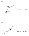
図10は、注目した地形変化点(注目地形変化点Pca)と傾斜方向点Psdを説明するモデル図である。この図に示す矢印が、中央に示す注目地形変化点Pcaの傾斜方向であり、その傾斜方向の終点となるのが傾斜方向点Psdである。この傾斜方向点Psdは、注目地形変化点Pcaの周囲にある周辺地形点Ps(つまり周辺単位区画BLs)から選ばれ、そのうち最も標高値が低いものを選択するとよい。図10の例では、注目地形変化点Pcaの周囲にある8個の周辺地形点Psのうち左下にある周辺地形点Ps6の標高値が最も低く、これが傾斜方向点Psdとして選択されている。 FIG. 10 is a model diagram for explaining the noted terrain change point (notable terrain change point Pca) and the inclination direction point Psd. The arrow shown in this figure is the inclination direction of the noted landform change point Pca shown in the center, and the end point of the inclination direction is the inclination direction point Psd. The inclination direction point Psd is selected from the peripheral terrain points Ps (that is, the peripheral unit sections BLs) around the target terrain change point Pca, and the one having the lowest altitude value may be selected. In the example of FIG. 10, the elevation value of the peripheral terrain point Ps6 at the lower left of the eight peripheral terrain points Ps around the attention terrain change point Pca is the lowest, and this is selected as the inclination direction point Psd.
注目地形変化点Pcaに対して傾斜方向点Psdが選択されると、その注目地形変化点Pcaが遷急点であるか遷緩点であるか判定する。この場合、注目地形変化点Pcaの平均傾斜量Icと傾斜方向点Psdの平均傾斜量Isを比較した結果に応じて判定することができる。図11は、注目地形変化点Pcaの平均傾斜量Icと傾斜方向点Psdの平均傾斜量Isを比較したモデル図であり、(a)は注目地形変化点Pcaが遷急点の場合、(b)は注目地形変化点Pcaが遷緩点の場合である。図11(a)に示すように、注目地形変化点Pcaの平均傾斜量Icが、傾斜方向点Psdの平均傾斜量Isよりも小さいときは、その注目地形変化点Pcaが遷急点であることが分かる。また、図11(b)に示すように、注目地形変化点Pcaの平均傾斜量Icが、傾斜方向点Psdの平均傾斜量Isよりも大きいときは、その注目地形変化点Pcaが遷緩点であることが分かる。 When the inclination direction point Psd is selected for the target landform change point Pca, it is determined whether the target landform change point Pca is a transition point or a transition point. In this case, the determination can be made according to a result of comparing the average inclination amount Ic of the target landform change point Pca and the average inclination amount Is of the inclination direction point Psd. FIG. 11 is a model diagram comparing the average inclination amount Ic of the noted landform change point Pca and the average inclination amount Is of the inclination direction point Psd. FIG. 11A shows a case where the noted landform change point Pca is a transition point. ) Is a case where the noted landform change point Pca is a transition point. As shown in FIG. 11A, when the average inclination amount Ic of the noted terrain change point Pca is smaller than the average inclination amount Is of the inclination direction point Psd, the noticed terrain change point Pca is a transition point. I understand. Further, as shown in FIG. 11B, when the average slope amount Ic of the target landform change point Pca is larger than the average slope amount Is of the tilt direction point Psd, the target landform change point Pca is a transition point. I understand that there is.
(地形変化線の生成)
遷急点又は遷緩点が選別されると、図8に示す地形変化線生成手段127によって緩急線又は遷緩線が生成される(Step210:図7)。緩急線は、隣接する遷急点どうしが順に繋がれていくことで生成され、一方の遷緩線は、隣接する遷緩点どうしが順に繋がれていくことで生成される。
(Generation of topographic change lines)
When the transition point or transition point is selected, the gradual change line or transition line is generated by the topographic change line generation means 127 shown in FIG. 8 (Step 210: FIG. 7). A gentle line is generated by connecting adjacent transition points in order, and one of the transition lines is generated by connecting adjacent transition points in order.
本願発明の地形変化点抽出システム、及び地形変化点抽出方法は、種々の斜面において地すべり地形や深層崩壊地形、表層・浅層崩壊地形を抽出する際に、極めて有効な手がかりを提供することができる。本願発明を利用すれば、地すべり地形等の抽出に役立つとともに、地すべり等のメカニズムの把握につながることを考えれば、自然災害を未然に防ぎ、被害を軽減させることが可能となり、産業上利用できるうえに社会的にも貢献が期待できる発明といえる。 The landform change point extraction system and landform change point extraction method of the present invention can provide extremely effective clues when extracting landslide topography, deep collapse topography, and surface / shallow collapse topography on various slopes. . If the invention of the present application is used, it will be useful for extraction of landslide topography, etc., and it will lead to grasp of the mechanism of landslide etc., so it will be possible to prevent natural disasters and reduce damage, and it can be used industrially. It can be said that the invention can be expected to contribute to society.
100 本願発明の地形変化点抽出システム
110 (地形変化点抽出システムの)条件設定手段
111 (条件設定手段の)地形モデル記憶手段
112 (条件設定手段の)地形モデル読出し手段
113 (条件設定手段の)サンプル領域抽出手段
114 (条件設定手段の)地形量算出手段
115 (条件設定手段の)散布図作成手段
116 (条件設定手段の)地形変化条件設定手段
117 (条件設定手段の)地形変化条件記憶手段
120 (地形変化点抽出システムの)地形変化抽出手段
121 (地形変化抽出手段の)地形量算出手段
122 (地形変化抽出手段の)地形変化条件読出し手段
123 (地形変化抽出手段の)地形変化点選別手段
124 (地形変化抽出手段の)適正判定手段
125 (地形変化抽出手段の)傾斜方向設定手段
126 (地形変化抽出手段の)緩急選別手段
127 (地形変化抽出手段の)地形変化線生成手段
130 (地形変化点抽出システムの)出力手段
AR 所定領域
BL 単位区画
TM 地形データ
DESCRIPTION OF
Claims (6)
前記地形モデルは、所定領域を平面分割して得られる多数の単位区画と、該単位区画が具備する標高値と、を含んで構成され、
単位区画に対して、平均傾斜量と傾斜標準偏差を求める地形量算出手段と、
オペレータの操作により、前記所定領域のうち地形の特徴に着目してサンプル領域を抽出するサンプル領域抽出手段と、
前記サンプル領域内にある単位区画の前記平均傾斜量及び前記傾斜標準偏差を、平均傾斜量軸及び傾斜標準偏差軸からなる2軸平面に配置して散布図を作成する散布図作成手段と、
前記散布図に基づいて、閾値線を設定するとともに、該閾値線を基準として上限閾値線及び下限閾値線を設定する地形変化条件設定手段と、
前記平均傾斜量及び前記傾斜標準偏差の組み合わせが前記上限閾値線と前記下限閾値線の間となる単位区画を、地形変化点として選別する地形変化点選別手段と、
を備え、
前記平均傾斜量は、単位区画の周辺にある複数の単位区画の組み合わせによって算出される複数の周辺傾斜量に基づいて求められ、
前記傾斜標準偏差は、複数の前記周辺傾斜量に基づいて求められる、
ことを特徴とする地形変化点抽出システム。 A system for extracting terrain change points using a terrain model,
The terrain model is configured to include a large number of unit sections obtained by dividing a predetermined region into planes, and elevation values provided in the unit sections.
Topographical amount calculation means for obtaining an average inclination amount and an inclination standard deviation for a unit block;
Sample region extraction means for extracting a sample region by paying attention to features of the terrain among the predetermined regions by the operation of the operator;
A scatter diagram creating means for creating a scatter diagram by arranging the average inclination amount and the inclination standard deviation of the unit sections in the sample region on a biaxial plane including an average inclination amount axis and an inclination standard deviation axis;
Based on the scatter diagram, while setting a threshold line, terrain change condition setting means for setting an upper limit threshold line and a lower limit threshold line based on the threshold line,
Topographic change point selection means for selecting, as a topographic change point, a unit block in which the combination of the average inclination amount and the inclination standard deviation is between the upper threshold line and the lower threshold line;
With
The average inclination amount is obtained based on a plurality of peripheral inclination amounts calculated by a combination of a plurality of unit sections around the unit section,
The inclination standard deviation is obtained based on a plurality of the peripheral inclination amounts.
Topographic change point extraction system characterized by that.
ことを特徴とする請求項1記載の地形変化点抽出システム。 The terrain change condition setting means obtains a regression line representing the relationship between the average inclination amount and the inclination standard deviation arranged in the scatter diagram, and sets the regression line as the threshold line.
The landform change point extraction system according to claim 1, wherein:
さらに備えたことを特徴とする請求項1又は請求項2記載の地形変化点抽出システム。 A terrain change line generating means for generating a terrain change line by connecting a plurality of the terrain change points,
The topographic change point extraction system according to claim 1 or 2, further comprising:
前記適正判定手段は、適正判定する地形変化点を注目地形変化点として認識するとともに、該注目地形変化点の周辺にある複数の単位区画のうち、地形変化点として選別された単位区画の数に基づいて、該注目地形変化点の適正を判定する、
ことを特徴とする請求項1乃至請求項3のいずれかに記載の地形変化点抽出システム。 For the terrain change point selected by the terrain change point selection means, it further comprises appropriate determination means for determining appropriateness as a terrain change point,
The appropriateness determination means recognizes the terrain change point to be determined as appropriate as the target terrain change point, and determines the number of unit sections selected as the terrain change point among the plurality of unit sections around the target terrain change point. On the basis of the appropriate terrain change point of interest,
The landform change point extraction system according to any one of claims 1 to 3, wherein
前記地形変化点に対して、遷緩点又は遷急点のいずれかに選別する緩急選別手段と、
をさらに備え、
前記傾斜方向設定手段は、傾斜方向を設定する地形変化点を注目地形変化点として認識するとともに、該注目地形変化点の周辺にある複数の単位区画のうち、最も標高値が小さい単位区画を傾斜方向点として抽出し、該傾斜方向点に向かう方向を該注目地形変化点の傾斜方向として設定し、
前記緩急選別手段は、前記注目地形変化点の前記平均傾斜量が前記傾斜方向点の前記平均傾斜量より大きいときに該注目地形変化点を遷緩点として選別し、前記注目地形変化点の前記平均傾斜量が前記傾斜方向点の前記平均傾斜量より小さいときに該注目地形変化点を遷急点として選別する、
ことを特徴とする請求項1乃至請求項4のいずれかに記載の地形変化点抽出システム。 An inclination direction setting means for setting an inclination direction of the topographic change point;
With respect to the terrain change point, a slow and rapid sorting means for sorting into either a transition point or a transition point;
Further comprising
The inclination direction setting means recognizes the terrain change point that sets the inclination direction as the noticed terrain change point, and inclines the unit area having the smallest altitude value from among the plurality of unit areas around the noticed terrain change point. Extract as a direction point, set the direction toward the slope direction point as the slope direction of the target terrain change point,
The gradual selection means selects the attention terrain change point as a transition point when the average inclination amount of the attention terrain change point is larger than the average inclination amount of the inclination direction point, and When the average inclination amount is smaller than the average inclination amount of the inclination direction point, the attention landform change point is selected as a transition point.
The topographic change point extraction system according to any one of claims 1 to 4, wherein
前記地形モデルは、所定領域を平面分割して得られる多数の単位区画と、該単位区画が具備する標高値と、を含んで構成され、
単位区画に対して、平均傾斜量と傾斜標準偏差を求める地形量算出工程と、
前記所定領域のうち地形の特徴に着目したサンプル領域を、オペレータが抽出するサンプル領域抽出工程と、
前記サンプル領域内にある単位区画の前記平均傾斜量及び前記傾斜標準偏差を、平均傾斜量軸及び傾斜標準偏差軸からなる2軸平面に配置して散布図を作成する散布図作成工程と、
前記散布図に基づいて、閾値線を設定するとともに、該閾値線を基準として上限閾値線及び下限閾値線を設定する地形変化条件設定工程と、
前記平均傾斜量及び前記傾斜標準偏差の組み合わせが前記上限閾値線と前記下限閾値線の間となる単位区画を、地形変化点として選別する地形変化点選別工程と、
を備え、
前記平均傾斜量は、単位区画の周辺にある複数の単位区画の組み合わせによって算出される複数の周辺傾斜量に基づいて求められ、
前記傾斜標準偏差は、複数の前記周辺傾斜量に基づいて求められる、
ことを特徴とする地形変化点抽出方法。 A method for extracting terrain change points using a terrain model,
The terrain model is configured to include a large number of unit sections obtained by dividing a predetermined region into planes, and elevation values provided in the unit sections.
Topographical amount calculation step for obtaining an average inclination amount and an inclination standard deviation for a unit block;
A sample region extraction step in which an operator extracts a sample region focusing on features of the terrain among the predetermined regions;
A scatter diagram creating step of creating a scatter diagram by arranging the average inclination amount and the inclination standard deviation of the unit section in the sample region on a biaxial plane composed of an average inclination amount axis and an inclination standard deviation axis;
Based on the scatter diagram, setting the threshold line, and setting the upper limit threshold line and the lower limit threshold line with reference to the threshold line, terrain change condition setting step,
A terrain change point selection step of selecting, as a terrain change point, a unit block in which the combination of the average inclination amount and the inclination standard deviation is between the upper limit threshold line and the lower limit threshold line;
With
The average inclination amount is obtained based on a plurality of peripheral inclination amounts calculated by a combination of a plurality of unit sections around the unit section,
The inclination standard deviation is obtained based on a plurality of the peripheral inclination amounts.
Topographic change point extraction method characterized by this.
Priority Applications (1)
| Application Number | Priority Date | Filing Date | Title |
|---|---|---|---|
| JP2016040510A JP6686262B2 (en) | 2016-03-02 | 2016-03-02 | Topographic change point extraction system and topographic change point extraction method |
Applications Claiming Priority (1)
| Application Number | Priority Date | Filing Date | Title |
|---|---|---|---|
| JP2016040510A JP6686262B2 (en) | 2016-03-02 | 2016-03-02 | Topographic change point extraction system and topographic change point extraction method |
Publications (2)
| Publication Number | Publication Date |
|---|---|
| JP2017156251A true JP2017156251A (en) | 2017-09-07 |
| JP6686262B2 JP6686262B2 (en) | 2020-04-22 |
Family
ID=59808714
Family Applications (1)
| Application Number | Title | Priority Date | Filing Date |
|---|---|---|---|
| JP2016040510A Active JP6686262B2 (en) | 2016-03-02 | 2016-03-02 | Topographic change point extraction system and topographic change point extraction method |
Country Status (1)
| Country | Link |
|---|---|
| JP (1) | JP6686262B2 (en) |
Cited By (5)
| Publication number | Priority date | Publication date | Assignee | Title |
|---|---|---|---|---|
| JP2019158530A (en) * | 2018-03-12 | 2019-09-19 | 朝日航洋株式会社 | Terrain state detector, method for detecting state of terrain, and terrain state detection program |
| KR102058626B1 (en) * | 2017-11-29 | 2019-12-23 | (주)엔젤스윙 | Method and Device for visualizing the change in topography |
| GB2590996A (en) * | 2019-08-15 | 2021-07-14 | China Inst Water Resources & Hydropower Res | Method and system for precisely positioning collapsed area of high slope |
| US11657437B2 (en) | 2017-11-29 | 2023-05-23 | Angelswing Inc | Method and apparatus for providing drone data by matching user with provider |
| JP7575537B1 (en) | 2023-07-24 | 2024-10-29 | 国際航業株式会社 | Displacement boundary extraction system |
Citations (2)
| Publication number | Priority date | Publication date | Assignee | Title |
|---|---|---|---|---|
| JP2005164421A (en) * | 2003-12-03 | 2005-06-23 | Sabo Frontier Foundation | Topographic deformation moving direction determination method and its determination system |
| JP2010266419A (en) * | 2009-05-18 | 2010-11-25 | Kokusai Kogyo Co Ltd | Analysis method of topographic change using topographic image and program thereof |
-
2016
- 2016-03-02 JP JP2016040510A patent/JP6686262B2/en active Active
Patent Citations (2)
| Publication number | Priority date | Publication date | Assignee | Title |
|---|---|---|---|---|
| JP2005164421A (en) * | 2003-12-03 | 2005-06-23 | Sabo Frontier Foundation | Topographic deformation moving direction determination method and its determination system |
| JP2010266419A (en) * | 2009-05-18 | 2010-11-25 | Kokusai Kogyo Co Ltd | Analysis method of topographic change using topographic image and program thereof |
Cited By (7)
| Publication number | Priority date | Publication date | Assignee | Title |
|---|---|---|---|---|
| KR102058626B1 (en) * | 2017-11-29 | 2019-12-23 | (주)엔젤스윙 | Method and Device for visualizing the change in topography |
| US11657437B2 (en) | 2017-11-29 | 2023-05-23 | Angelswing Inc | Method and apparatus for providing drone data by matching user with provider |
| JP2019158530A (en) * | 2018-03-12 | 2019-09-19 | 朝日航洋株式会社 | Terrain state detector, method for detecting state of terrain, and terrain state detection program |
| JP7333163B2 (en) | 2018-03-12 | 2023-08-24 | 朝日航洋株式会社 | Terrain state detection device, terrain state detection method, and terrain state detection program |
| GB2590996A (en) * | 2019-08-15 | 2021-07-14 | China Inst Water Resources & Hydropower Res | Method and system for precisely positioning collapsed area of high slope |
| JP7575537B1 (en) | 2023-07-24 | 2024-10-29 | 国際航業株式会社 | Displacement boundary extraction system |
| JP2025016851A (en) * | 2023-07-24 | 2025-02-05 | 国際航業株式会社 | Displacement boundary extraction system |
Also Published As
| Publication number | Publication date |
|---|---|
| JP6686262B2 (en) | 2020-04-22 |
Similar Documents
| Publication | Publication Date | Title |
|---|---|---|
| US8116530B2 (en) | Map change detection device, map change detection method, and program | |
| JP4545219B1 (en) | Analysis method of topographic change using topographic image and program thereof | |
| JP6686262B2 (en) | Topographic change point extraction system and topographic change point extraction method | |
| JP6179913B2 (en) | Columnar object extraction method, columnar object extraction program, and columnar object extraction device | |
| KR20200091324A (en) | Learning method and learning device for object detector with hardware optimization based on cnn for detection at distance or military purpose using image concatenation, and testing method and testing device using the same | |
| CN115761279B (en) | Spatial layout similarity detection method, device, storage medium and apparatus | |
| JP2015125092A (en) | Measurement result consistency determination method and measurement result consistency determination apparatus | |
| JP6146731B2 (en) | Coordinate correction apparatus, coordinate correction program, and coordinate correction method | |
| JP6514901B2 (en) | Survey data processing device | |
| CN112184900A (en) | Method and device for determining elevation data and storage medium | |
| JP6746851B2 (en) | Terrain classification system and terrain classification method | |
| JP6018959B2 (en) | Data analysis apparatus, data analysis method, and program | |
| CN116383451B (en) | A map segmentation method, device, electronic equipment and storage medium | |
| JP4438418B2 (en) | Three-dimensional data processing method and apparatus | |
| JP2006039629A (en) | Disaster prevention business plan support method and system | |
| JP4203599B2 (en) | Topographic data processing program | |
| CN113052474A (en) | Cross crossing key part early warning method and system based on power grid | |
| JP4314371B2 (en) | Topographic data processing program | |
| JP4203601B2 (en) | Topographic data processing program | |
| JP7575537B1 (en) | Displacement boundary extraction system | |
| CN114494136B (en) | Satellite image coverage detection method, device, equipment and storage medium | |
| JP2002150270A (en) | Three-dimensional model generation method and apparatus, and recording medium recording execution program of this method | |
| JP7580091B1 (en) | Information processing device, information processing method, and computer program | |
| JP7512532B1 (en) | Computer system, dimension measurement method, and semiconductor device manufacturing system | |
| JP2004118820A (en) | Topographic data processing program |
Legal Events
| Date | Code | Title | Description |
|---|---|---|---|
| A521 | Request for written amendment filed |
Free format text: JAPANESE INTERMEDIATE CODE: A523 Effective date: 20160323 |
|
| A621 | Written request for application examination |
Free format text: JAPANESE INTERMEDIATE CODE: A621 Effective date: 20190204 |
|
| A977 | Report on retrieval |
Free format text: JAPANESE INTERMEDIATE CODE: A971007 Effective date: 20191127 |
|
| A131 | Notification of reasons for refusal |
Free format text: JAPANESE INTERMEDIATE CODE: A131 Effective date: 20191203 |
|
| A521 | Request for written amendment filed |
Free format text: JAPANESE INTERMEDIATE CODE: A523 Effective date: 20191205 |
|
| TRDD | Decision of grant or rejection written | ||
| A01 | Written decision to grant a patent or to grant a registration (utility model) |
Free format text: JAPANESE INTERMEDIATE CODE: A01 Effective date: 20200303 |
|
| A61 | First payment of annual fees (during grant procedure) |
Free format text: JAPANESE INTERMEDIATE CODE: A61 Effective date: 20200310 |
|
| R150 | Certificate of patent or registration of utility model |
Ref document number: 6686262 Country of ref document: JP Free format text: JAPANESE INTERMEDIATE CODE: R150 |
|
| R250 | Receipt of annual fees |
Free format text: JAPANESE INTERMEDIATE CODE: R250 |
|
| R250 | Receipt of annual fees |
Free format text: JAPANESE INTERMEDIATE CODE: R250 |
|
| R250 | Receipt of annual fees |
Free format text: JAPANESE INTERMEDIATE CODE: R250 |
|
| R250 | Receipt of annual fees |
Free format text: JAPANESE INTERMEDIATE CODE: R250 |