JP2017156465A - Drive device, lithography device, cooling method, and method for manufacturing article - Google Patents
Drive device, lithography device, cooling method, and method for manufacturing article Download PDFInfo
- Publication number
- JP2017156465A JP2017156465A JP2016038128A JP2016038128A JP2017156465A JP 2017156465 A JP2017156465 A JP 2017156465A JP 2016038128 A JP2016038128 A JP 2016038128A JP 2016038128 A JP2016038128 A JP 2016038128A JP 2017156465 A JP2017156465 A JP 2017156465A
- Authority
- JP
- Japan
- Prior art keywords
- refrigerant
- coil
- state
- housing
- condensing
- Prior art date
- Legal status (The legal status is an assumption and is not a legal conclusion. Google has not performed a legal analysis and makes no representation as to the accuracy of the status listed.)
- Pending
Links
Images



Classifications
-
- G—PHYSICS
- G03—PHOTOGRAPHY; CINEMATOGRAPHY; ANALOGOUS TECHNIQUES USING WAVES OTHER THAN OPTICAL WAVES; ELECTROGRAPHY; HOLOGRAPHY
- G03F—PHOTOMECHANICAL PRODUCTION OF TEXTURED OR PATTERNED SURFACES, e.g. FOR PRINTING, FOR PROCESSING OF SEMICONDUCTOR DEVICES; MATERIALS THEREFOR; ORIGINALS THEREFOR; APPARATUS SPECIALLY ADAPTED THEREFOR
- G03F7/00—Photomechanical, e.g. photolithographic, production of textured or patterned surfaces, e.g. printing surfaces; Materials therefor, e.g. comprising photoresists; Apparatus specially adapted therefor
- G03F7/70—Microphotolithographic exposure; Apparatus therefor
- G03F7/70691—Handling of masks or workpieces
- G03F7/70758—Drive means, e.g. actuators, motors for long- or short-stroke modules or fine or coarse driving
-
- G—PHYSICS
- G03—PHOTOGRAPHY; CINEMATOGRAPHY; ANALOGOUS TECHNIQUES USING WAVES OTHER THAN OPTICAL WAVES; ELECTROGRAPHY; HOLOGRAPHY
- G03F—PHOTOMECHANICAL PRODUCTION OF TEXTURED OR PATTERNED SURFACES, e.g. FOR PRINTING, FOR PROCESSING OF SEMICONDUCTOR DEVICES; MATERIALS THEREFOR; ORIGINALS THEREFOR; APPARATUS SPECIALLY ADAPTED THEREFOR
- G03F7/00—Photomechanical, e.g. photolithographic, production of textured or patterned surfaces, e.g. printing surfaces; Materials therefor, e.g. comprising photoresists; Apparatus specially adapted therefor
- G03F7/20—Exposure; Apparatus therefor
-
- G—PHYSICS
- G03—PHOTOGRAPHY; CINEMATOGRAPHY; ANALOGOUS TECHNIQUES USING WAVES OTHER THAN OPTICAL WAVES; ELECTROGRAPHY; HOLOGRAPHY
- G03F—PHOTOMECHANICAL PRODUCTION OF TEXTURED OR PATTERNED SURFACES, e.g. FOR PRINTING, FOR PROCESSING OF SEMICONDUCTOR DEVICES; MATERIALS THEREFOR; ORIGINALS THEREFOR; APPARATUS SPECIALLY ADAPTED THEREFOR
- G03F7/00—Photomechanical, e.g. photolithographic, production of textured or patterned surfaces, e.g. printing surfaces; Materials therefor, e.g. comprising photoresists; Apparatus specially adapted therefor
- G03F7/70—Microphotolithographic exposure; Apparatus therefor
- G03F7/70691—Handling of masks or workpieces
- G03F7/70775—Position control, e.g. interferometers or encoders for determining the stage position
-
- G—PHYSICS
- G03—PHOTOGRAPHY; CINEMATOGRAPHY; ANALOGOUS TECHNIQUES USING WAVES OTHER THAN OPTICAL WAVES; ELECTROGRAPHY; HOLOGRAPHY
- G03F—PHOTOMECHANICAL PRODUCTION OF TEXTURED OR PATTERNED SURFACES, e.g. FOR PRINTING, FOR PROCESSING OF SEMICONDUCTOR DEVICES; MATERIALS THEREFOR; ORIGINALS THEREFOR; APPARATUS SPECIALLY ADAPTED THEREFOR
- G03F7/00—Photomechanical, e.g. photolithographic, production of textured or patterned surfaces, e.g. printing surfaces; Materials therefor, e.g. comprising photoresists; Apparatus specially adapted therefor
- G03F7/70—Microphotolithographic exposure; Apparatus therefor
- G03F7/708—Construction of apparatus, e.g. environment aspects, hygiene aspects or materials
- G03F7/70858—Environment aspects, e.g. pressure of beam-path gas, temperature
-
- G—PHYSICS
- G03—PHOTOGRAPHY; CINEMATOGRAPHY; ANALOGOUS TECHNIQUES USING WAVES OTHER THAN OPTICAL WAVES; ELECTROGRAPHY; HOLOGRAPHY
- G03F—PHOTOMECHANICAL PRODUCTION OF TEXTURED OR PATTERNED SURFACES, e.g. FOR PRINTING, FOR PROCESSING OF SEMICONDUCTOR DEVICES; MATERIALS THEREFOR; ORIGINALS THEREFOR; APPARATUS SPECIALLY ADAPTED THEREFOR
- G03F7/00—Photomechanical, e.g. photolithographic, production of textured or patterned surfaces, e.g. printing surfaces; Materials therefor, e.g. comprising photoresists; Apparatus specially adapted therefor
- G03F7/70—Microphotolithographic exposure; Apparatus therefor
- G03F7/708—Construction of apparatus, e.g. environment aspects, hygiene aspects or materials
- G03F7/70858—Environment aspects, e.g. pressure of beam-path gas, temperature
- G03F7/70866—Environment aspects, e.g. pressure of beam-path gas, temperature of mask or workpiece
- G03F7/70875—Temperature, e.g. temperature control of masks or workpieces via control of stage temperature
-
- H—ELECTRICITY
- H02—GENERATION; CONVERSION OR DISTRIBUTION OF ELECTRIC POWER
- H02K—DYNAMO-ELECTRIC MACHINES
- H02K41/00—Propulsion systems in which a rigid body is moved along a path due to dynamo-electric interaction between the body and a magnetic field travelling along the path
- H02K41/02—Linear motors; Sectional motors
- H02K41/03—Synchronous motors; Motors moving step by step; Reluctance motors
- H02K41/031—Synchronous motors; Motors moving step by step; Reluctance motors of the permanent magnet type
-
- H—ELECTRICITY
- H02—GENERATION; CONVERSION OR DISTRIBUTION OF ELECTRIC POWER
- H02K—DYNAMO-ELECTRIC MACHINES
- H02K9/00—Arrangements for cooling or ventilating
- H02K9/19—Arrangements for cooling or ventilating for machines with closed casing and closed-circuit cooling using a liquid cooling medium, e.g. oil
- H02K9/20—Arrangements for cooling or ventilating for machines with closed casing and closed-circuit cooling using a liquid cooling medium, e.g. oil wherein the cooling medium vaporises within the machine casing
-
- H—ELECTRICITY
- H10—SEMICONDUCTOR DEVICES; ELECTRIC SOLID-STATE DEVICES NOT OTHERWISE PROVIDED FOR
- H10P—GENERIC PROCESSES OR APPARATUS FOR THE MANUFACTURE OR TREATMENT OF DEVICES COVERED BY CLASS H10
- H10P72/00—Handling or holding of wafers, substrates or devices during manufacture or treatment thereof
- H10P72/50—Handling or holding of wafers, substrates or devices during manufacture or treatment thereof for positioning, orientation or alignment
Landscapes
- Physics & Mathematics (AREA)
- General Physics & Mathematics (AREA)
- Health & Medical Sciences (AREA)
- Engineering & Computer Science (AREA)
- Epidemiology (AREA)
- Life Sciences & Earth Sciences (AREA)
- Atmospheric Sciences (AREA)
- Toxicology (AREA)
- Environmental & Geological Engineering (AREA)
- Public Health (AREA)
- Power Engineering (AREA)
- Electromagnetism (AREA)
- Combustion & Propulsion (AREA)
- Chemical & Material Sciences (AREA)
- Exposure And Positioning Against Photoresist Photosensitive Materials (AREA)
- Motor Or Generator Cooling System (AREA)
- Container, Conveyance, Adherence, Positioning, Of Wafer (AREA)
Abstract
【課題】 コイルの温度変動を低減できる駆動装置、リソグラフィ装置、冷却方法を提供すること【解決手段】 本発明に係る駆動装置200は、磁石8とコイル10を有し、コイル10に電流が流れることで物体6を駆動する電磁アクチュエータと、液体状態から気化することでコイル10を冷却する第1冷媒24と、液体状態の前記第1冷媒に浸された前記コイルと、を収容する収容手段と、気体状態の第1冷媒24を凝縮する凝縮手段71、80と、第1冷媒24の状態の変化を検出する検出手段38と、を有し、凝縮手段71、80は、検出手段38の検出結果に基づいて第1冷媒24の凝縮量を調整する調整手段32、86、88を有する。【選択図】 図2PROBLEM TO BE SOLVED: To provide a driving device, a lithographic apparatus, and a cooling method capable of reducing a temperature variation of a coil. A storage means for storing the electromagnetic actuator that drives the object 6, the first refrigerant 24 that cools the coil 10 by vaporizing from the liquid state, and the coil that is immersed in the first refrigerant in the liquid state; , Condensing means 71 and 80 for condensing the first refrigerant 24 in the gas state, and detecting means 38 for detecting a change in the state of the first refrigerant 24, and the condensing means 71 and 80 are detected by the detecting means 38. Adjustment means 32, 86, 88 for adjusting the amount of condensation of the first refrigerant 24 based on the result is provided. [Selection] Figure 2
Description
本発明は、駆動装置、リソグラフィ装置、冷却方法、および物品の製造方法に関する。 The present invention relates to a driving device, a lithographic apparatus, a cooling method, and an article manufacturing method.
コイルと磁石により駆動する電磁アクチュエータを有する駆動装置において、コイルに電流が流れるとコイルが発熱する。したがって、例えば、マスクに形成されたパターンを基板に転写するリソグラフィ装置等のステージ装置に当該駆動装置を搭載すると、ステージ装置まわりの空間の温度が変動してしまう。レーザ干渉計等の計測器をステージ装置の位置計測に使用すると、この温度変動が位置計測の誤差要因となってしまう。 In a drive device having an electromagnetic actuator driven by a coil and a magnet, the coil generates heat when a current flows through the coil. Therefore, for example, when the driving device is mounted on a stage apparatus such as a lithography apparatus that transfers the pattern formed on the mask to the substrate, the temperature of the space around the stage apparatus fluctuates. When a measuring instrument such as a laser interferometer is used for position measurement of the stage device, this temperature variation becomes an error factor of position measurement.
特許文献1には、コイルの冷却に関する技術が開示されている。特許文献1に記載の駆動装置の固定子は、コイルおよび第1冷媒が収容された密閉容器の第1筐体と、第1筐体の上面に設けられた第2筐体とを有する。第1冷媒は気体と液体が平衡状態の物質であり、第2筐体の内部を循環する第2冷媒は所定の温度に温調された冷媒である。第1冷媒は液体状態の第1冷媒と接触しているコイルの熱を奪いながら気化する。気化した第1冷媒を第2冷媒で冷却することによって、第1冷媒を再び液体状態に戻している。 Patent Document 1 discloses a technique related to coil cooling. The stator of the drive device described in Patent Literature 1 includes a first casing of a sealed container in which a coil and a first refrigerant are accommodated, and a second casing provided on the upper surface of the first casing. The first refrigerant is a substance in which a gas and a liquid are in an equilibrium state, and the second refrigerant circulating in the second housing is a refrigerant whose temperature is adjusted to a predetermined temperature. The first refrigerant is vaporized while taking heat of the coil in contact with the first refrigerant in the liquid state. The first refrigerant is returned to the liquid state again by cooling the vaporized first refrigerant with the second refrigerant.
特許文献1では、第1冷媒がコイルから奪った第1冷媒の熱が徐々に第1筐体の上面まで伝熱し、第1筐体と第2筐体との間で温度差が生じてはじめて第1冷媒が凝縮し始める。このとき、第1冷媒の凝縮が開始されるまでの間にも第1冷媒は気化を続ける。熱の移動よりも圧力の変動のほうが応答性が速いため、凝縮が開始されるまでの間に第1筐体の内部の圧力が上昇してしまう。 In Patent Document 1, the heat of the first refrigerant taken away from the coil by the first refrigerant is gradually transferred to the upper surface of the first casing, and a temperature difference is generated between the first casing and the second casing. The first refrigerant begins to condense. At this time, the first refrigerant continues to vaporize until the condensation of the first refrigerant is started. Since the pressure fluctuation is faster than the heat transfer, the pressure inside the first casing rises before the condensation starts.
蒸気圧と沸点の関係を示すClausius−Clapeyronの式によれば、蒸気圧の上昇に伴い液体の沸点が上昇することが知られている。すなわち、特許文献1に記載の駆動装置では第1筐体の内部の圧力が上昇することによって第1冷媒の沸点が上昇してしまうことを意味する。これにより、第1冷媒の凝縮によって第1筐体の内部の圧力が元に戻るまでの間にコイルの温度が上昇しやすくなるためコイルの温度変動が生じやすくなる恐れがある。 According to the Clausius-Clapeyron equation showing the relationship between the vapor pressure and the boiling point, it is known that the boiling point of the liquid increases as the vapor pressure increases. That is, in the drive device described in Patent Document 1, it means that the boiling point of the first refrigerant increases due to an increase in the pressure inside the first housing. As a result, the temperature of the coil is likely to rise before the pressure inside the first housing returns to its original state due to the condensation of the first refrigerant, and thus there is a risk that the temperature fluctuation of the coil will easily occur.
本発明は上記課題に鑑みなされたものであり、コイルの温度変動を低減できる駆動装置、リソグラフィ装置、冷却方法を提供することを目的とする。 SUMMARY An advantage of some aspects of the invention is that it provides a driving apparatus, a lithography apparatus, and a cooling method that can reduce temperature fluctuations of a coil.
本発明は、磁石とコイルを有し、前記コイルに電流が流れることで物体を駆動する電磁アクチュエータと、液体状態から気化することで前記コイルを冷却する第1冷媒と、液体状態の前記第1冷媒に浸された前記コイルと、を収容する収容手段と、気体状態の前記第1冷媒を凝縮する凝縮手段と、前記第1冷媒の状態の変化を検出する検出手段と、を有し、前記凝縮手段は、前記検出手段の検出結果に基づいて前記第1冷媒の凝縮量を調整する調整手段を有することを特徴とする。 The present invention includes a magnet and a coil, an electromagnetic actuator that drives an object when a current flows through the coil, a first refrigerant that cools the coil by evaporating from a liquid state, and the first in a liquid state. A storage means for storing the coil immersed in the refrigerant; a condensing means for condensing the first refrigerant in a gaseous state; and a detection means for detecting a change in the state of the first refrigerant, The condensing means has an adjusting means for adjusting the amount of condensation of the first refrigerant based on the detection result of the detecting means.
本発明の駆動装置、リソグラフィ装置、冷却方法によれば、コイル温度変動を低減できる。 According to the driving device, lithographic apparatus, and cooling method of the present invention, coil temperature fluctuations can be reduced.
[第1実施形態]
図1(a)は、第1実施形態に係るステージ装置(位置決め装置)100およびステージ装置100の位置を計測する干渉計60の構成を示す正面図である。図1(b)はステージ装置100を+Z方向から見た図である。鉛直方向の軸をZ軸、当該Z軸に垂直な平面内で互いに直交する2軸をX軸及びY軸としている。
[First Embodiment]
FIG. 1A is a front view illustrating a configuration of a stage device (positioning device) 100 and an
ステージ装置100は物体2の位置決めをする装置である。ステージ装置100は、物体2とY軸方向に延伸しており干渉計60からの計測光を反射するミラー4とが載置されたステージ(物体)6と、ステージ6を駆動させる駆動装置200とを有する。
The
駆動装置200は、磁石8とコイル10とを有し、コイル10に電流が流れることによって駆動される電磁アクチュエータを有する。本実施形態に係る電磁アクチュエータは、駆動装置200の固定子12として複数のコイル10を有し、駆動装置200の可動子18(図1(b)では不図示)として磁石8が搭載された磁石可動式(ムービングマグネット式)とする。複数のコイル10の配列方向であるX軸方向に沿って可動子18が移動する。
The
図1(b)に示すように、ステージ装置100は、1つのステージ6に対して、平行に設けられた2つの固定子12および2つの可動子18を有する。これにより、Z軸まわりの回転方向へのチルトを規制しつつ物体2を移動させる。
As shown in FIG. 1B, the
1つの可動子18は、固定子12と対向するように、すなわち固定子12に対して−Y方向側と+Y方向側に位置する2つの磁石8と、2つの磁石8と接続された1つのヨーク20を有する。図1(a)において+Y方向側の磁石は不図示である。所定位置のコイル10に順次電流が流れると、ガイド22に案内されながら可動子18がX軸方向に移動する。可動子18の移動によって、可動子18と接続されているステージ6もX軸方向に移動する。
One
駆動装置200は電流源11も有し、電流源11は、配線13を介して、ステージ6の目標位置に応じて所定の位置のコイル10に電流を供給する。
The
固定子12は、複数のコイル10を収容する第1筐体(第1収容手段)14と、第1筐体14の上部に設けられた第2筐体16とを有する。
The
第1筐体14の構成は後で詳述する。第2筐体(第2収容手段)16は第1筐体に沿って構成された筐体であって、その内部に冷媒28を収容する。第2筐体16は一端に設けられた冷媒28を供給する供給口16aと他端に設けられた冷媒28を排出する排出口16bとを有する。冷媒28は、第2筐体16の内部および循環系80(図2に図示)の流路を循環している。すなわち、冷媒28は、第1筐体に供給される冷媒24(後で詳述)とは独立した系を流れる。
The configuration of the
干渉計60は、光源62、ビームスプリッタ64、参照用のミラー66、および検出器68を有する。光源62から出射されたレーザ光70を、ビームスプリッタ64が参照用のミラー66および計測用のミラー4に向かう光に分岐する。ビームスプリッタ64は、参照用のミラー66で反射された光とミラー4で反射された光とを検出器68に入射させる。検出器68ではそれぞれの光を重ね合わせて生じる干渉縞の強度を計測することで、ステージ6のX位置を計測する。
The
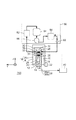
図2は、第1実施形態に係る駆動装置200の構成を示す図である。図1(a)のA−A矢視図と、図1(a)では図示が省略されていた循環系80とを示している。
FIG. 2 is a diagram illustrating a configuration of the
駆動装置200は、気化により気体状態となった冷媒24を凝縮する凝縮手段を有する。凝縮手段は、気体状態の冷媒24の状態の変化を検出する検出手段38の検出結果に基づいて冷媒24の凝縮量を調整する調整手段を有する。検出手段38については後述する。
The
調整手段は、第1筐体14の内部および第1筐体14の内部と連通する空間(連通空間)の少なくとも一方における気体状態の冷媒24の熱(冷媒24の有する熱)を調整する手段である。
The adjusting means is means for adjusting the heat of the refrigerant 24 in the gas state (heat of the refrigerant 24) in at least one of the inside of the
本実施形態に係る凝縮手段は、冷媒24とは独立した系を流れる冷媒28を用いて冷媒24を凝縮させる。凝縮手段として、循環系80と調整手段としてのペルチェ素子32とを有する。ペルチェ素子32は、第1筐体14の内部の熱を冷媒28の流路に放熱する。なお、冷媒24と独立した系を流れるとは、冷媒24が流れる空間と隔てられた空間を流れることを意味する。凝縮手段は、他に、凝縮フィン34、放熱フィン36を有していてもよい。
The condensing means according to the present embodiment condenses the refrigerant 24 using the refrigerant 28 that flows in a system independent of the refrigerant 24. As a condensing means, a
第1筐体14は、液体状態から気化することでコイル10を冷却する冷媒(第1冷媒)24と、液体状態の冷媒24に浸されたコイル10とを収容している。
The
第1筐体14の内部は、第1筐体14の内部と外部との間を気体の行き来がほとんどできないように封止された閉空間である。Oリング等のシール部材を用いていれば、後述の検出手段38と接続された配線(不図示)又は配線13が第1筐体14の内部と接続されていたり、所定量の冷媒24を入れるための開け閉め可能な開口(不図示)等が第1筐体14に設けられていても良い。
The inside of the
冷媒24は、ステージ装置100を使用する環境の管理温度に近い沸点を有し、液体状態と気体状態との平衡状態で存在している。コイル10が発熱した場合、冷媒24が気化することですぐにコイル10を冷却することができる。気体状態の冷媒24は第1筐体14内の上側の空間26に存在している。なお、本明細書では、液体状態の冷媒24に対してのみ符号24で示している。
The refrigerant 24 has a boiling point close to the management temperature of the environment in which the
冷媒24はコイル10に直接接触するので導電性の低い冷媒が好ましい。導電性の低い冷媒とすることによって、コイル10のショートを防ぐことができる。
Since the refrigerant 24 is in direct contact with the
冷媒24の例として、管理温度が室温程度であれば、水、アルコール、エーテル、ハイフドロフルオロエーテル(以下、HFEという)、フロリナート等を用いることができる。 As an example of the refrigerant 24, water, alcohol, ether, hydrofluoroether (hereinafter referred to as HFE), fluorinate, or the like can be used if the management temperature is about room temperature.
大気圧の環境で冷媒24が気化しない場合は、空間26を予め減圧してもよい。これにより冷媒24の沸点を下げることができる。例えば、23℃の環境下でHFEを使用する場合は、空間26を約60kPa(abs)まで減圧することで、第1筐体14内に気体状態と液体状態との平衡状態のHFEを封入することができる。
When the refrigerant 24 does not vaporize in an atmospheric pressure environment, the
第1筐体14は、さらに、コイル10を支持するための支持材25と後述する凝縮フィン34を収容している。
The
第2筐体16の外部の可動子18側には断熱材料で構成された部材30が設けられている。固定子12の熱が変動した場合であったとしても、可動子18や物体2に熱が伝わることを防止(低減)できる。第2筐体16自身を断熱材料で構成していてもよい。断熱材料として、ポリスチレン、ポリウレタンなどの発泡プラスチックや、グラスウール等を用いてもよい。
A
循環系80は、供給口16aに温度調整された冷媒28を供給し、排出口16bから排出された冷媒28を回収して再び供給口16aに供給するように冷媒28を循環させる機構を有する。冷媒28はステージ装置100の管理温度で液体状態の材料であっても気体状態の材料であってもよい。
The
循環系80は、冷却器82、タンク84、ポンプ86、熱交換器88、および熱交換器88の温度を計測するセンサ90を有する。冷却器82は第2筐体16から回収した冷媒28を一度冷却する。冷却時に生じた排熱は循環系80の外部に捨てられる。冷却器82によって冷却された冷媒28はタンク84内で一時的に貯蔵される。ポンプ86は、単位時間当たり所定量ずつタンク84内の冷媒28を熱交換器88に送る。
The
センサ90は、熱交換器88によって調整された冷媒28の温度を計測し、センサ90による計測結果が所定の温度を示すように熱交換器88は冷媒28を温度調整する。
The
第2筐体16に温度調整された冷媒28を供給できるのであれば、循環系80は冷媒28が循環する系でなくてもよい。
As long as the temperature-controlled
ペルチェ素子32は、第1筐体14と第2筐体16の接合部分に設けられており、第1筐体14の内部、または第2筐体16の内部すなわち第2冷媒のうち、一方から他方に熱を移動させることが可能な素子である。特に、本実施形態では、検出手段38の検出結果に基づき後述の制御部40によって算出された熱を、制御部40の指示にしたがって冷媒28から第1筐体14に移動させる。
The
なお、ペルチェ素子32は第1筐体14の内部の第2筐体16側、あるいは第2筐体16の内部の第1筐体14側に設けられていても良い。
Note that the
第1筐体14のペルチェ素子32側には凝縮フィン34が、第2筐体16のペルチェ素子32側には凝縮フィン34と同形状の放熱フィン36が設けられている。凝縮フィン34の凝縮部と放熱フィン36の放熱部とがペルチェ素子32に対して互いに逆方向を向くように設けられている。凝縮フィン34は凝縮した冷媒24が集まる部分である。放熱フィン36はペルチェ素子32によって第1筐体14内部から移動した熱を冷媒28中に放熱する部分である。
A
図2に示すように、凝縮フィン34および放熱フィン36は複数の針形状に形成されていることが好ましい。気化した冷媒24との接触面積を広くでき、凝縮効率を高めることができる。放熱フィン36の場合は、第2冷媒への排熱効率を高めることができる。本実施形態では説明の簡易化のために、凝縮フィン34と放熱フィン36を同形状としているが、凝縮フィン34と放熱フィン36の形状が異なっていてもよい。
As shown in FIG. 2, the
本実施形態に係る検出手段38は、気体状態の冷媒24の圧力変化を検出する手段である。検出手段38は、センサ38aと算出部38bとを有する。センサ38aは第1筐体14の内部の底部に設けられており、気体状態の冷媒24の圧力変化に応じて変化する、液体状態の冷媒24から受ける圧力を計測する。センサ38aに接続された算出部38bは、センサ38aが検出した圧力と所定の圧力との差を算出する。所定の圧力とは、コイル10に電流を流していない状態(以下、アイドル状態という)での冷媒24の飽和蒸気圧である。なお、算出部38bの機能が、制御部40に備えられていてもよい。
The detection means 38 according to the present embodiment is means for detecting a pressure change of the refrigerant 24 in a gas state. The detection means 38 includes a
制御部40は、CPUおよびメモリ(ROM、RAM等)を有する。制御部40は検出手段38と接続されており、検出手段38の検出結果に基づいて、コイル10の温度変動を低減するために冷媒24の凝縮すべき量(以下、目標凝縮量という)に対応する熱の熱量を決定する。さらに目標凝縮量に基づいて、ペルチェ素子32によって第2冷媒6から第1筐体14に移動させる熱の熱量を決定する。
The
ここで目標凝縮量は、検出手段38が検出した圧力変化を低減する(変化量をゼロに近づける)凝縮量であることが好ましい。以下では、検出手段38が検出した圧力変化に対応する熱をペルチェ素子32が移動させる場合の目標凝縮量の算出方法について説明する。
Here, the target condensation amount is preferably a condensation amount that reduces the pressure change detected by the detection means 38 (makes the change amount close to zero). Below, the calculation method of the target condensation amount in case the
第1筐体14の体積をV、気体状態の冷媒24の密度をρ[g/l]、アイドル状態における第1筐体14の内部の圧力をP0[Pa]、アイドル状態での気体状態の冷媒24の体積をVgとする。制御部40のメモリにはV、ρ、Vg、P0、冷媒24の潜熱L[J/g]の値が予め記憶されている。センサ38aが計測した圧力の変化量をP[Pa]、この圧力P0から圧力Pの変化に伴い、気化した冷媒24の量をΔm[g]、P0−P=ΔPとする。気化した量は微量で液体状態の冷媒24の体積V1は変わらないとすると、
Vg=V−V1=一定が成り立つ。
The volume of the
Vg = V−V1 = constant holds.
アイドル状態では、気体状態の冷媒24の量Gは、式(1)で表される。
G=P・Vg・ρ/P0[g]・・・(1)
In the idle state, the amount G of the refrigerant 24 in the gas state is expressed by the equation (1).
G = P · Vg · ρ / P0 [g] (1)
また、ボイルの法則により式(2)が成り立つ。
(P+ΔP)・Vg={P0・Vg・(ρ+Δm)}/ρ ・・・(2)
Moreover, Formula (2) is formed by Boyle's law.
(P + ΔP) · Vg = {P0 · Vg · (ρ + Δm)} / ρ (2)
目標凝縮量M[g]は、Δmと等しいので、式(1)、(2)より、式(3)で表される。
M=Δm=ρ・vg・ΔP/P0・・・(3)
Since the target condensation amount M [g] is equal to Δm, it is expressed by the equation (3) from the equations (1) and (2).
M = Δm = ρ · vg · ΔP / P0 (3)
潜熱L[J/g]を用いて、ペルチェ素子32で移動すべき熱量Q[J]は式(4)で表される。
Q=M・L=ρ・vg・ΔP・L/P0・・・(4)
The amount of heat Q [J] to be moved by the
Q = M · L = ρ · vg · ΔP · L / P0 (4)
(冷却方法)
駆動装置200におけるコイル10の冷却方法について説明する。駆動装置200を駆動させるため、電流源11がコイル10に電流を流し始める。電流を流している間、検出手段38は常時、あるいは所定の時間間隔で冷媒24の圧力を検出する。コイル10が発熱すると、冷媒24が気化してコイル10を冷却する。気体状態の冷媒24が増加したことによって冷媒24のセンサ38aが圧力の増加を検出すると、算出部38bが所定の圧力との差を算出する。検出手段38は、算出した圧力変化を制御部40に送る。
(Cooling method)
A method for cooling the
制御部40は式(4)に基づいてペルチェ素子32で移動すべき熱の熱量Qを算出し、ペルチェ素子32に指示する。ペルチェ素子32が熱量Qを移動し、冷媒24が凝縮される。
The
第1筐体14の内部で気体状態となった冷媒24が凝縮により再度液体状態となることによって、第1筐体14の内部の圧力が所定の圧力まで戻る。検出手段38が第1筐体14の内部の圧力が所定の圧力よりも下がったことを検出した場合は、ペルチェ素子32が第1筐体14の内部の熱を第2冷媒に移動させて凝縮量を低減するように調整してもよい。
The refrigerant 24 that has become a gas state inside the
なお、制御部40は、熱量Qを取得できるのであれば、必ずしも毎時算出しなくてもよい。算出部38bから算出された圧力変化と熱量Qとの対応関係に基づいて、熱量Qを決定してもよい。制御部40は、PID制御により凝縮量調整の追従制御を行ってもよい。
Note that the
このようにして、駆動装置200において、検出手段38の検出結果に基づいてペルチェ素子32が冷媒24の凝縮量を調整する。凝縮量を調整することによって冷媒24の圧力および冷媒24の沸点を所定の値に保つことができ、冷媒24の沸点上昇によるコイル10の温度上昇を抑制することができる。このようにして、本実施形態に係る駆動装置200および冷却方法によれば、検出手段38およびペルチェ素子32を用いて冷媒24の凝縮量を調整しない場合に比べて、コイル10の温度変動を低減することができる。
In this way, in the
一般的に、空間を介して熱が所定距離だけ伝達する速度よりも、当該所定距離だけ離れた位置に対して気体の圧力変化が伝達する速度のほうが速い。すなわち、本実施形態であれば、冷媒24の圧力変化は、コイル10の温度上昇分の熱が空間26を介して冷媒28へ伝達する速度よりも応答性が早い。応答の速い圧力変化に基づいて冷媒24を凝縮させるので、検出手段による冷媒24の状態の変化を検出を行わない特許文献1に記載の駆動装置に比べて冷媒24の沸点上昇を抑制し、コイル10の温度変動を低減することができる。
Generally, the speed at which a change in pressure of gas is transmitted to a position separated by a predetermined distance is faster than the speed at which heat is transmitted through a space for a predetermined distance. That is, according to the present embodiment, the pressure change of the refrigerant 24 is faster in response than the speed at which heat corresponding to the temperature rise of the
これにより、コイル10からステージ装置100のある空間に熱が伝搬し、レーザ光70の光路上における温度変動による計測精度の悪化を低減できる。また、可動子18を介してステージ6に熱が伝搬し、物体2が一時的に変形することを低減できる。
Thereby, heat propagates from the
センサ38aは、第1筐体14の底部に設けられていなくともよい。例えば空間26に設けられていても良い。ペルチェ素子32は第1筐体14の内部の熱を第1筐体14の外部に放熱することができるため、冷媒28の流路を含む循環系80が無くても構わない。
The
駆動装置200は、第1筐体14の内部に、冷媒24を撹拌する撹拌部を設けていてもよい。撹拌部は、羽根付き部材を回転させる方式、穴の開いた球体を回転させる方式などである。撹拌部として、発熱量が小さいものを選択することが好ましい。撹拌することにより冷媒24の気化によって生じた気泡がコイル10に付着することによる冷媒24とコイル10との接触面積の低下を抑制することができる。
The
ステージ装置100の位置検出に、干渉計60のかわりにエンコーダ(不図示)を用いても良い。エンコーダならびにエンコーダスケールを保持する部分の温度変化を低減でき、ステージ装置100の位置の計測精度の悪化を抑制することができる。
An encoder (not shown) may be used instead of the
[第2実施形態]
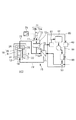
図3は、第2実施形態に係る駆動装置300の構成を示す図である。本実施形態に係る凝縮手段も、冷媒24とは独立した系を流れる冷媒28を用いて冷媒24を凝縮させる。調整手段として、ペルチェ素子32の代わりに冷媒28の温度を制御する温度制御手段を用いる点が、駆動装置200とは異なる。その他の構成は駆動装置200と同様であるため説明を省略する。なお、循環系80においては、温度制御手段とは熱交換器88である。
[Second Embodiment]
FIG. 3 is a diagram illustrating a configuration of the driving apparatus 300 according to the second embodiment. The condensing means according to this embodiment also condenses the refrigerant 24 using the refrigerant 28 that flows in a system independent of the refrigerant 24. It differs from the driving
駆動装置300におけるコイル10の冷却方法は以下の通りである。
The cooling method of the
検出手段38による圧力の検出結果は制御部40に送られ、制御部40は第2筐体16の内部を流れる冷媒28の温度を決定する。制御部40は、当該決定した温度を熱交換器88に対して設定する。検出手段38が圧力を検出した第2筐体16を流れる冷媒28の温度が低くなるように調整する。
The detection result of the pressure by the detection means 38 is sent to the
熱交換器88が冷媒28の温度を低くさせることで、第2筐体16の温度は第1筐体14に比べて温度が低くなる。よって、第1筐体14から冷媒28に熱が移動することにより、冷媒24の凝縮を増加させることができる。これにより、変化した冷媒24の圧力をアイドル状態の圧力まで近づけるあるいは一致させることができる。制御部40は、検出手段38が検出した圧力変化が無くなった時点で、熱交換器88に設定する温度を、変更する前の温度に戻す。
As the
制御部40が決定する冷媒28の温度は、検出手段38が圧力変化を検出する前より所定の温度だけ低い温度であってもよいし、検出手段38が検出した圧力変化に応じて異なる温度に設定してもよい。
The temperature of the refrigerant 28 determined by the
このように、駆動装置300において、検出手段38の検出結果に基づいて熱交換器88が冷媒24の凝縮量を調整する。凝縮量を調整することによって冷媒24の圧力および冷媒24の沸点を所定の値に保つことができ、冷媒24の沸点上昇によるコイル10の温度上昇を抑制することができる。このようにして、本実施形態に係る駆動装置300および冷却方法によれば、検出手段38および熱交換器88を用いて冷媒24の凝縮量を調整しない場合に比べて、コイル10の温度変動を低減することができる。
Thus, in the drive device 300, the
よって、コイル10からステージ装置100のある空間に熱が伝搬し、レーザ光70の光路上における温度変動による計測精度の悪化を低減できる。また、可動子18を介してステージ6に熱が伝搬し、物体2が一時的に変形することを低減できる。
Therefore, heat propagates from the
本実施形態は、ペルチェ素子を用いる場合に比べて、第1筐体14の内部から第2筐体16の内部に大きな熱量の熱を移動させることができる。したがって、特に、コイル10に流す電流量が大きいステージ装置の駆動装置として適している。例えば、ステージ装置100が微動ステージと当該微動ステージより大きな移動量で移動する粗動ステージを有する場合は、粗動ステージの駆動装置として用いることが好ましい。
In the present embodiment, a large amount of heat can be transferred from the inside of the
[第3実施形態]
図4は、第3実施形態に係る駆動装置400の構成を示す図である。本実施形態に係る凝縮手段も、冷媒24とは独立した系を流れる冷媒28を用いて冷媒24を凝縮させる。調整手段として、熱交換器88に加え、さらに冷媒28の流量を制御する流量制御手段を用いる点が、駆動装置300とは異なる。その他の構成は駆動装置300と同様であるため説明を省略する。なお、循環系80においては、流量度制御手段とはポンプ86である。
[Third Embodiment]
FIG. 4 is a diagram illustrating a configuration of a
駆動装置400におけるコイル10の冷却方法は以下の通りである。
The cooling method of the
検出手段38による圧力の検出結果は制御部40に送られ、制御部40が第2筐体16の内部を流れる冷媒28の流量を決定する。制御部40は、熱交換器88に指示して冷媒28の温度を所定温度だけ低く設定するとともに、ポンプ86に指示して第2筐体16を流れる冷媒28の流量を増加させる。第2筐体16の温度は第1筐体14に比べて温度が低くなることで、第1筐体14から冷媒28に熱が移動する。
The detection result of the pressure by the detection means 38 is sent to the
制御部40は、検出手段38が検出した圧力変化が無くなった時点で、熱交換器88に設定する温度およびポンプ86に設定した冷媒28の流量を、変更する前の値に戻す。
The
駆動装置400は、第2実施形態と同様の効果を有する。さらに、熱交換器88およびセンサ90のみを用いて凝縮量を調整する場合に比べて、ポンプ86を使用することで冷媒24の単位時間当たりの凝縮量を増やすことができる。
The
[第4実施形態]
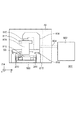
図5は、第4実施形態に係る駆動装置500の構成を示す図である。駆動装置500は、駆動装置300と比べて、第2筐体16、凝縮フィン34、および放熱フィン36が無い。代わりに凝縮器71、シリンダ72、圧力制御部73、検出手段74、および筐体14の内部と連通する空間75を有する。本実施形態に係る凝縮手段も、冷媒24とは独立した系を流れる冷媒28を用いて冷媒24を凝縮させる。本実施形態に係る凝縮手段は、冷媒28を循環させている循環系80と凝縮器71である。本実施形態に係る調整手段は熱交換器88である。
[Fourth Embodiment]
FIG. 5 is a diagram illustrating a configuration of a
ピストン72aは、空間75の一部でもある空間76と、圧力制御部73によって圧力の制御された空間77とを隔てている。
The
空間75は、圧力制御部73によって所定の圧力に背圧されている。
The
当該所定の圧力とは、第1筐体16の管理温度における冷媒24の飽和蒸気圧(所定の圧力)である。すなわち、コイル10が発熱していない間((コイル10に電流を流していない間)の筐体16の内部の圧力である。圧力制御部73は、例えば、空間77に対する圧縮空気の入出力を調整できる圧力調整弁が好ましい。
The predetermined pressure is the saturated vapor pressure (predetermined pressure) of the refrigerant 24 at the management temperature of the
これにより、冷媒24の気化が進行するにつれて、ピストン72aの位置は空間76と空間77の圧力が保たれるように移動する。すなわち空間75は、冷媒24の体積に応じて体積が可変な空間である。
As a result, as the refrigerant 24 evaporates, the position of the
冷媒24は、背圧にさからってピストン72aを移動させるという機械仕事をする。
The refrigerant 24 performs the mechanical work of moving the
冷媒24の封入量は、アイドル状態において、空間75と空間76とがほぼ同体積になる量が好ましい。ピストン72aが移動した際のシリンダ72の内壁に衝突を防ぎ、冷媒24が有する熱を機械仕事に変換し続けることができる。
The amount of the refrigerant 24 enclosed is preferably an amount in which the
空間75は、筐体14の内部の上部と連通し且つ気体状態となった冷媒24が通る配管78、空間76、凝縮器71のうち冷媒24が通る空間71a、筐体14の内部の下部と連通し且つ凝縮して液体状態の冷媒24が通る配管79を含む。
The
凝縮器71は冷媒24の流れる空間71aと冷媒28の流れる空間71bとに分離されており、冷媒28と空間75との間で熱を交換する(移動させる)。凝縮器71は例えばヒートポンプである。
The condenser 71 is separated into a space 71 a through which the refrigerant 24 flows and a space 71 b through which the refrigerant 28 flows, and exchanges (moves) heat between the refrigerant 28 and the
検出手段74はピストン72aの位置を検出するセンサ74aとセンサ74aが検出した位置と基準位置との差を算出する算出部74bを有する。算出部74bは、算出結果を制御部40に入力する。すなわち、検出手段74はピストン72aの位置変化を検出することにより、気体状態の冷媒24の状態の変化、具体的には第1冷媒の体積変化を検出している。基準位置とは、アイドル状態におけるピストン72aの位置のことをいう。
The detection means 74 has a
制御部40は、検出手段74の検出結果に基づいて、制御部40は第2筐体16の内部を流れる冷媒28の温度を決定する。制御部40は、当該決定した温度を熱交換器88に対して設定する。
The
熱交換器88が冷媒28の温度を調整することにより、凝縮器71において凝縮させる冷媒24の凝縮量を調整する。
The
(冷却方法)
コイル10に電流が流れ、発熱すると、コイル10と接触している冷媒24がコイル10の熱を吸収して気化する。冷媒24が気化すると、冷媒24の圧力が増加しそうになる。このとき、気体状態の冷媒24がピストン72aを移動させながら断熱膨張することによって、冷媒24の圧力の増加および冷媒24の圧力の増加に伴う沸点の上昇を低減することができる。
(Cooling method)
When a current flows through the
また、シリンダ72の空間の体積には上限があるので冷媒24を凝縮を促す必要が生じる。そこで、検出手段74の検出結果に基づいて、冷媒24の体積をアイドル状態における体積に戻すように、制御部40は第2筐体16の内部を流れる冷媒28の温度を決定する。制御部40は、当該決定した温度を熱交換器88に対して設定する。
Further, since the volume of the space of the
制御部40は下記の演算に基づき目標凝縮量および当該目標凝縮量に対応する設定温度を求めてもよいし、予め決められた所定の温度を設定してもよい。
The
目標凝縮量の算出方法について説明する。目標凝縮量は、冷媒24の潜熱をL[J/g]ピストン72aの背圧面積をA、空間77の圧力をP、微小時間Δtの間にピストンがΔx移動したとすると、目標凝縮量C2は式(2)で表される。
C2=(P・A・Δx/Δt)/L[g/sec] ・・・(2)
A method for calculating the target condensation amount will be described. Assuming that the latent heat of the refrigerant 24 is A, the back pressure area of the
C2 = (P · A · Δx / Δt) / L [g / sec] (2)
目標凝縮量に対応する冷媒28の設定温度を算出し、熱交換器88は制御部40の指示を受けて冷媒28の温度を低下させる。これにより、凝縮器71における冷媒24の凝縮量を増加させ、変化した冷媒24の体積をアイドル状態の体積まで近づけるあるいは一致させることができる。冷媒24の体積が減少するにつれてピストン72aの位置は基準位置に近づく。制御部40は、検出手段74が検出した体積変化が無くなった時点で、熱交換器88に設定する温度を、変更する前の温度に戻す。
The set temperature of the refrigerant 28 corresponding to the target condensation amount is calculated, and the
検出手段38が冷媒24の体積がアイドル状態よりも小さくなったことを検出した場合は、熱交換器88に設定する温度を上昇させて凝縮量を調整してもよい。
When the detection means 38 detects that the volume of the refrigerant 24 is smaller than that in the idle state, the condensation amount may be adjusted by increasing the temperature set in the
このように、駆動装置500において、検出手段74の検出結果に基づいて熱交換器88が冷媒24の凝縮量を調整する。凝縮量を調整することによって冷媒24の圧力および冷媒24の沸点を所定の値に保つことができ、冷媒24の沸点上昇によるコイル10の温度上昇を抑制することができる。このようにして、本実施形態に係る駆動装置500および冷却方法によれば、検出手段74および熱交換器88を用いて冷媒24の凝縮量を調整しない場合に比べて、コイル10の温度変動を低減することができる。
Thus, in the
よって、コイル10からステージ装置100のある空間に熱が伝搬し、レーザ光70の光路上における温度変動による計測精度の悪化を低減できる。また、可動子18を介してステージ6に熱が伝搬し、物体2が一時的に変形することを低減できる。
Therefore, heat propagates from the
さらに駆動装置500では、冷媒24が、背圧にさからってピストン72aを移動させるという機械仕事をする。よってコイル10より奪った熱を機械仕事に変えて消費することができる。第1〜第3の実施形態に比べて、循環系80における排熱量を低減することができる。
Further, in the
さらに空間75において冷媒24を凝縮させているため、可動子18から離れた位置で冷媒24の熱を放出することができる。よって可動子18とともに移動するステージ6に熱が伝わりにくくすることができる。さらに、空間75の位置は自由に決定できるので、第1〜第3実施形態のように狭い空間内に第2筐体16を設ける必要が無く、駆動装置の設計の自由度を増すことができる。
Furthermore, since the refrigerant 24 is condensed in the
凝縮量の調整手段として、第1実施形態のようにペルチェ素子32を用いたり、第3実施形態のようにポンプ86を用いても良い。あるいは、適宜これらを併用してもよい。
As a means for adjusting the amount of condensation, the
[第5実施形態]
図6は、駆動装置200を搭載したステージ装置100を有するリソグラフィ装置800の構成を示す図である。リソグラフィ装置800は、基板810に光を露光する露光装置である。
[Fifth Embodiment]
FIG. 6 is a diagram showing a configuration of a
基板810上にパターンを形成するパターン形成部として、光源802、照明光学系806、および投影光学系808を有する。
A
光源802から出射したKrFエキシマレーザ光(波長248nm)は、導光部804、照明光学系806、および投影光学系808を通過してステージ装置100上に載置された基板810(対象物)に照射される。投影光学系808は、基板810にレチクル(マスク)812に形成された回路パターン等のパターンを縮小投影する。これによりレチクル812のパターンを基板810上に転写する。
The KrF excimer laser light (wavelength 248 nm) emitted from the
ステージ装置100は、前述の物体2でもある、基板810を位置決めする。干渉計60は、ステージ6の位置や姿勢を計測することで、基板810の位置を計測する。マウント814は、設置面816からの振動が投影光学系を支持する支持材に伝わらないように除振する装置である。ステージ装置100はレチクル812を位置決めする。
The
制御部40は、干渉計60による計測に基づいて、レチクル812と基板810との位置決めを制御する。
The
ステージ装置100は、第1実施形態と同様にコイル10の発熱を抑制することができる。これにより、コイル10で生じた熱が基板に伝わり、基板が変形することによる重ね合わせ精度の低下を抑制することができる。また、干渉計60の光路の空気の温度変動に起因して生じるステージ装置100の位置決め精度の低下を抑制することができる。
The
駆動装置200は、レチクル812を移動させるステージ装置817に搭載されていてもよい。また、ステージ装置100やステージ装置817には、駆動装置300、400、500のいずれか、またはこれらを適宜組み合わせた構成の駆動装置が搭載されていてもよい。
The
リソグラフィ装置800は、前述の装置に限られない。g線(波長436nm)、ArFレーザ光(波長193nm)、EUV光(波長13nm)等の光線を用いて基板を露光しパターンを形成する各種露光装置でもよい。3次元形状のパターンの形成された型を用いてレジストの硬化パターンを形成するインプリント装置、あるいは荷電粒子線を基板に照射してパターンを描画する描画装置でもよい。
The
[その他の実施形態]
第1実施形態、第2実施形態、および第3実施形態のうち、2つ以上の実施形態を組み合わせて実施してもよい。例えば、冷媒24の凝縮量を調整する調整手段として、第2実施形態の温度制御手段および第3実施形態の流量制御手段を両方使用してもよい。駆動装置200〜500は複数の第1筐体14を有しており、それぞれの第1筐体14が1つのコイル10を収容していてもよい。
[Other Embodiments]
You may implement combining 2 or more embodiment among 1st Embodiment, 2nd Embodiment, and 3rd Embodiment. For example, both the temperature control unit of the second embodiment and the flow rate control unit of the third embodiment may be used as the adjustment unit that adjusts the condensation amount of the refrigerant 24. The driving
1つの第1筐体14内に収容するコイル10の数は、固定子12のコイル10全てでなくてもよい。1つずつ、あるいは所定個数ずつコイル10を収容した分割された第1筐体14が連なったもので、固定子12が構成されていても良い。ペルチェ素子32も全てのコイル10に対して1つの長いペルチェ素子32が設けられていなくてもヨーク20、1つ、あるいは所定個数のコイル10ずつ設けられていても良い。なお、第1筐体14が分割されている場合には、少なくとも第1筐体14の個数だけペルチェ素子32は必要である。
The number of
制御部40は、目標凝縮量を毎回算出しなくてもよい。圧力変化または体積変化に対応する目標凝縮量に関するテーブルを有している場合には、当該テーブルより目標凝縮量を決定しても良い。
The
制御部40は、制御部40が実行する機能を全て備えていれば、別個の制御基板の集合体であってもよいし、1つの制御基板であってもよい。
As long as the
気体状態の冷媒24の状態の変化を検出する手段は、検出手段38、74の他、気体状態の冷媒24の、圧力変化、体積変化、および温度変化のうち少なくとも1つを検出する手段であればよい。 The means for detecting the change in the state of the refrigerant 24 in the gas state may be a means for detecting at least one of the pressure change, the volume change, and the temperature change of the refrigerant 24 in addition to the detection means 38 and 74. That's fine.
温度変化を検出する場合は、当該温度変化を検出する手段のセンサは、第1筐体14中の液体状態の冷媒24に配置されていることが好ましい。空間26を介してコイル10の温度変化分の熱が冷媒28に伝わるまでの時間よりも早く、コイル10の温度上昇を検出することができる。
When detecting a temperature change, the sensor of the means for detecting the temperature change is preferably arranged in the liquid state refrigerant 24 in the
駆動装置200〜500は、可動子18が移動するムービングマグネット方式に限らず、コイル10が移動するムービングコイル方式でもよい。物体2を直線移動させるステージ装置に限らず、回転方向に移動させる装置でもよい。基板810を位置決めをするステージ装置の他、たとえば光学素子の位置決めをするステージ装置であってもよい。
The driving
駆動装置200〜500は、リソグラフィ装置に搭載するステージ装置に限らず、その他の高精度な位置決めが要求される装置に搭載される駆動機構であってもよい。例えば、リソグラフィ装置が半導体露光装置の場合は、露光光を遮光するマスキングブレード、ステージ装置の移動に伴う反力を低減する反力キャンセラなどの駆動機構でもよい。例えば、リソグラフィ装置がインプリント装置の場合は、3次元形状パターンの形成されたモールドやインプリント材を供給する供給部を駆動させる駆動機構でもよい。
The driving
[物品の製造方法]
リソグラフィ装置を用いて形成したパターンは、各種物品を製造する際に一時的に用いられる。物品とは、電気回路素子、光学素子、MEMS、記録素子、センサ、或いは、型等である。電気回路素子としては、DRAM、SRAM、フラッシュメモリ、MRAMのような、揮発性或いは不揮発性の半導体メモリや、LSI、CCD、イメージセンサ、FPGAのような半導体素子等が挙げられる。型としては、インプリント用のモールド等が挙げられる。
[Product Manufacturing Method]
A pattern formed using a lithographic apparatus is temporarily used when manufacturing various articles. The article is an electric circuit element, an optical element, a MEMS, a recording element, a sensor, or a mold. Examples of the electric circuit elements include volatile or nonvolatile semiconductor memories such as DRAM, SRAM, flash memory, and MRAM, and semiconductor elements such as LSI, CCD, image sensor, and FPGA. Examples of the mold include an imprint mold.
リソグラフィ装置を用いて形成したパターンは、基板の加工工程においてエッチング又はイオン注入等が行われた後、レジストマスクは除去される。リソグラフィ装置として露光装置や描画装置などを用いた場合は、前述の加工工程の前にレジストを現像する。リソグラフィ装置としてインプリント装置を用いることで形成したレジストの硬化パターンは、そのまま上記物品の少なくとも一部の構成部材として用いてもよい。 The resist mask is removed after the pattern formed using the lithography apparatus is etched or ion-implanted in the substrate processing step. When an exposure apparatus, a drawing apparatus, or the like is used as the lithography apparatus, the resist is developed before the above-described processing steps. The resist cured pattern formed by using an imprint apparatus as a lithography apparatus may be used as a constituent member of at least a part of the article.
以上、本発明の好ましい実施形態について説明したが、本発明はこれらの実施形態に限定されないことはいうまでもなく、その要旨の範囲内で種々の変形及び変更が可能である。 As mentioned above, although preferable embodiment of this invention was described, it cannot be overemphasized that this invention is not limited to these embodiment, A various deformation | transformation and change are possible within the range of the summary.
200、300、400、500 駆動装置
6 ステージ(物体)
8 磁石
10 コイル
14 第1筐体(収容手段)
24 冷媒(第1冷媒)
32 ペルチェ素子(調整手段)
38 センサ(検出手段)
40 制御部
71 凝縮器(凝縮手段)
80 循環系(凝縮手段)
86 ポンプ(調整手段)
88 熱交換器(調整手段)
200, 300, 400, 500
8
24 Refrigerant (first refrigerant)
32 Peltier element (adjustment means)
38 sensor (detection means)
40 Control unit 71 Condenser (condensing means)
80 Circulation system (condensing means)
86 Pump (Adjustment means)
88 Heat exchanger (adjustment means)
Claims (14)
液体状態から気化することで前記コイルを冷却する第1冷媒と、液体状態の前記第1冷媒に浸された前記コイルと、を収容する収容手段と、
気体状態の前記第1冷媒を凝縮する凝縮手段と、
前記第1冷媒の状態の変化を検出する検出手段と、を有し、
前記凝縮手段は、前記検出手段の検出結果に基づいて前記第1冷媒の凝縮量を調整する調整手段を有することを特徴とする駆動装置。 An electromagnetic actuator having a magnet and a coil, and driving an object by passing an electric current through the coil;
Storage means for storing the first refrigerant that cools the coil by evaporating from the liquid state, and the coil immersed in the first refrigerant in the liquid state;
Condensing means for condensing the first refrigerant in a gaseous state;
Detecting means for detecting a change in the state of the first refrigerant,
The driving device according to claim 1, wherein the condensing unit includes an adjusting unit that adjusts a condensing amount of the first refrigerant based on a detection result of the detecting unit.
前記調整手段は、前記第2冷媒の流量を制御する流量制御手段および前記第2冷媒の温度を制御する温度制御手段の少なくとも一方であることを特徴とする請求項1乃至6のいずれか1項に記載の駆動装置。 The condensing means condenses the first refrigerant in a gaseous state using a second refrigerant flowing in a system independent of the first refrigerant,
The adjustment means is at least one of a flow rate control means for controlling the flow rate of the second refrigerant and a temperature control means for controlling the temperature of the second refrigerant. The drive device described in 1.
前記基板に対してパターンを形成するパターン形成部とを有することを特徴とするリソグラフィ装置。 A positioning device comprising the driving device according to any one of claims 1 to 11 and positioning a substrate;
A lithographic apparatus, comprising: a pattern forming unit that forms a pattern on the substrate.
前記気化により気体状態になった前記第1冷媒の状態の変化を検出する検出工程と、
気体状態の前記第1冷媒を凝縮させる凝縮工程と、を有し、
前記凝縮工程は、前記検出工程における検出結果に基づいて前記第1冷媒の凝縮量を調整する工程を有することを特徴とするコイルの冷却方法。 A coil cooling method in which a coil of an electromagnetic actuator is immersed in a liquid state refrigerant and the coil is cooled by evaporating the liquid state from the liquid state, wherein the state of the first refrigerant is changed to a gas state by the vaporization. A detection process for detecting changes in
A condensing step for condensing the first refrigerant in a gaseous state,
The method of cooling a coil, wherein the condensing step includes a step of adjusting an amount of condensation of the first refrigerant based on a detection result in the detecting step.
前記工程でパターンの形成された基板を加工する工程と、
を有することを特徴とする物品の製造方法。 Forming a pattern on a substrate using the lithographic apparatus according to claim 12;
A step of processing the substrate on which the pattern is formed in the step;
A method for producing an article comprising:
Priority Applications (7)
| Application Number | Priority Date | Filing Date | Title |
|---|---|---|---|
| JP2016038128A JP2017156465A (en) | 2016-02-29 | 2016-02-29 | Drive device, lithography device, cooling method, and method for manufacturing article |
| EP17759709.3A EP3425452A4 (en) | 2016-02-29 | 2017-02-20 | DRIVE DEVICE, LITHOGRAPHIC DEVICE, COOLING METHOD, AND ARTICLE MANUFACTURING METHOD |
| CN201780013965.6A CN108700831B (en) | 2016-02-29 | 2017-02-20 | Drive unit, lithographic apparatus, cooling method and method of manufacturing an article |
| TW106105601A TWI635694B (en) | 2016-02-29 | 2017-02-20 | Driving device, lithographic device, cooling method, and article manufacturing method |
| KR1020187026795A KR102190676B1 (en) | 2016-02-29 | 2017-02-20 | Driving apparatus, lithographic apparatus, cooling method and manufacturing method of article |
| PCT/JP2017/006096 WO2017150243A1 (en) | 2016-02-29 | 2017-02-20 | Drive device, lithography device, cooling method, and method for manufacturing article |
| US16/112,336 US20180364593A1 (en) | 2016-02-29 | 2018-08-24 | Drive unit, lithography apparatus, cooling method, and article manufacturing method |
Applications Claiming Priority (1)
| Application Number | Priority Date | Filing Date | Title |
|---|---|---|---|
| JP2016038128A JP2017156465A (en) | 2016-02-29 | 2016-02-29 | Drive device, lithography device, cooling method, and method for manufacturing article |
Publications (2)
| Publication Number | Publication Date |
|---|---|
| JP2017156465A true JP2017156465A (en) | 2017-09-07 |
| JP2017156465A5 JP2017156465A5 (en) | 2019-04-11 |
Family
ID=59744011
Family Applications (1)
| Application Number | Title | Priority Date | Filing Date |
|---|---|---|---|
| JP2016038128A Pending JP2017156465A (en) | 2016-02-29 | 2016-02-29 | Drive device, lithography device, cooling method, and method for manufacturing article |
Country Status (7)
| Country | Link |
|---|---|
| US (1) | US20180364593A1 (en) |
| EP (1) | EP3425452A4 (en) |
| JP (1) | JP2017156465A (en) |
| KR (1) | KR102190676B1 (en) |
| CN (1) | CN108700831B (en) |
| TW (1) | TWI635694B (en) |
| WO (1) | WO2017150243A1 (en) |
Cited By (2)
| Publication number | Priority date | Publication date | Assignee | Title |
|---|---|---|---|---|
| JP2020071321A (en) * | 2018-10-30 | 2020-05-07 | キヤノン株式会社 | Cooling device, light source device, exposure device, and article manufacturing method |
| JP2021037106A (en) * | 2019-09-03 | 2021-03-11 | 富士フイルム株式会社 | Electronic cassette |
Families Citing this family (3)
| Publication number | Priority date | Publication date | Assignee | Title |
|---|---|---|---|---|
| JP7025256B2 (en) * | 2018-03-16 | 2022-02-24 | キヤノン株式会社 | Manufacturing methods for stage equipment, lithography equipment, and articles |
| CN108390511B (en) * | 2018-04-26 | 2023-07-28 | 北京建筑大学 | Switch reluctance motor and control method, device and system thereof |
| JP7483397B2 (en) | 2020-02-07 | 2024-05-15 | キヤノン株式会社 | Transport System |
Citations (15)
| Publication number | Priority date | Publication date | Assignee | Title |
|---|---|---|---|---|
| JPS51141463U (en) * | 1975-05-07 | 1976-11-15 | ||
| JPS58145855A (en) * | 1982-02-23 | 1983-08-31 | 株式会社鷺宮製作所 | Controller for flow rate of refrigerant |
| JPS63173716A (en) * | 1987-01-10 | 1988-07-18 | Sanden Corp | Cooling device |
| JPH05243438A (en) * | 1992-02-15 | 1993-09-21 | Fuji Electric Co Ltd | Electronic device cooling device |
| JP2001168564A (en) * | 1999-12-13 | 2001-06-22 | Yaskawa Electric Corp | Heat exchanger for electronic equipment housing |
| JP2002078314A (en) * | 2000-08-24 | 2002-03-15 | Nikon Corp | Armature unit, electromagnetic actuator, stage device, exposure apparatus, and device manufacturing method using the same |
| JP2002291219A (en) * | 2001-03-29 | 2002-10-04 | Canon Inc | Electromagnetic actuator, linear motor, exposure apparatus, semiconductor device manufacturing method, semiconductor manufacturing factory, and exposure apparatus maintenance method |
| JP2003133211A (en) * | 2001-10-26 | 2003-05-09 | Canon Inc | Device manufacturing apparatus and temperature control method therefor |
| JP2003214733A (en) * | 2002-01-25 | 2003-07-30 | Daikin Ind Ltd | Refrigerating apparatus |
| JP2004031673A (en) * | 2002-06-26 | 2004-01-29 | Nikon Corp | Linear motor device, stage device, and exposure device |
| JP2005064391A (en) * | 2003-08-19 | 2005-03-10 | Canon Inc | Optical member cooling method, cooling apparatus, exposure apparatus, and device manufacturing method |
| JP2005142283A (en) * | 2003-11-05 | 2005-06-02 | Nikon Corp | Temperature control apparatus, temperature control method, exposure apparatus, and device manufacturing method |
| JP2011096983A (en) * | 2009-11-02 | 2011-05-12 | Furukawa Electric Co Ltd:The | Cooling device |
| JP2013105815A (en) * | 2011-11-11 | 2013-05-30 | Nikon Corp | Mobile device and exposure equipment |
| JP2015191959A (en) * | 2014-03-27 | 2015-11-02 | 日立アプライアンス株式会社 | Cooling device |
Family Cites Families (3)
| Publication number | Priority date | Publication date | Assignee | Title |
|---|---|---|---|---|
| US20040244963A1 (en) * | 2003-06-05 | 2004-12-09 | Nikon Corporation | Heat pipe with temperature control |
| JP2006006050A (en) | 2004-06-18 | 2006-01-05 | Nikon Corp | Armature unit, electromagnetic actuator, stage apparatus, and exposure apparatus |
| JP2009060773A (en) * | 2007-09-04 | 2009-03-19 | Canon Inc | Driving device, planar motor using the same, and exposure apparatus using the same |
-
2016
- 2016-02-29 JP JP2016038128A patent/JP2017156465A/en active Pending
-
2017
- 2017-02-20 WO PCT/JP2017/006096 patent/WO2017150243A1/en not_active Ceased
- 2017-02-20 KR KR1020187026795A patent/KR102190676B1/en active Active
- 2017-02-20 CN CN201780013965.6A patent/CN108700831B/en not_active Expired - Fee Related
- 2017-02-20 TW TW106105601A patent/TWI635694B/en active
- 2017-02-20 EP EP17759709.3A patent/EP3425452A4/en not_active Withdrawn
-
2018
- 2018-08-24 US US16/112,336 patent/US20180364593A1/en not_active Abandoned
Patent Citations (15)
| Publication number | Priority date | Publication date | Assignee | Title |
|---|---|---|---|---|
| JPS51141463U (en) * | 1975-05-07 | 1976-11-15 | ||
| JPS58145855A (en) * | 1982-02-23 | 1983-08-31 | 株式会社鷺宮製作所 | Controller for flow rate of refrigerant |
| JPS63173716A (en) * | 1987-01-10 | 1988-07-18 | Sanden Corp | Cooling device |
| JPH05243438A (en) * | 1992-02-15 | 1993-09-21 | Fuji Electric Co Ltd | Electronic device cooling device |
| JP2001168564A (en) * | 1999-12-13 | 2001-06-22 | Yaskawa Electric Corp | Heat exchanger for electronic equipment housing |
| JP2002078314A (en) * | 2000-08-24 | 2002-03-15 | Nikon Corp | Armature unit, electromagnetic actuator, stage device, exposure apparatus, and device manufacturing method using the same |
| JP2002291219A (en) * | 2001-03-29 | 2002-10-04 | Canon Inc | Electromagnetic actuator, linear motor, exposure apparatus, semiconductor device manufacturing method, semiconductor manufacturing factory, and exposure apparatus maintenance method |
| JP2003133211A (en) * | 2001-10-26 | 2003-05-09 | Canon Inc | Device manufacturing apparatus and temperature control method therefor |
| JP2003214733A (en) * | 2002-01-25 | 2003-07-30 | Daikin Ind Ltd | Refrigerating apparatus |
| JP2004031673A (en) * | 2002-06-26 | 2004-01-29 | Nikon Corp | Linear motor device, stage device, and exposure device |
| JP2005064391A (en) * | 2003-08-19 | 2005-03-10 | Canon Inc | Optical member cooling method, cooling apparatus, exposure apparatus, and device manufacturing method |
| JP2005142283A (en) * | 2003-11-05 | 2005-06-02 | Nikon Corp | Temperature control apparatus, temperature control method, exposure apparatus, and device manufacturing method |
| JP2011096983A (en) * | 2009-11-02 | 2011-05-12 | Furukawa Electric Co Ltd:The | Cooling device |
| JP2013105815A (en) * | 2011-11-11 | 2013-05-30 | Nikon Corp | Mobile device and exposure equipment |
| JP2015191959A (en) * | 2014-03-27 | 2015-11-02 | 日立アプライアンス株式会社 | Cooling device |
Cited By (4)
| Publication number | Priority date | Publication date | Assignee | Title |
|---|---|---|---|---|
| JP2020071321A (en) * | 2018-10-30 | 2020-05-07 | キヤノン株式会社 | Cooling device, light source device, exposure device, and article manufacturing method |
| JP7202142B2 (en) | 2018-10-30 | 2023-01-11 | キヤノン株式会社 | Cooling device, light source device, exposure device, and article manufacturing method |
| JP2021037106A (en) * | 2019-09-03 | 2021-03-11 | 富士フイルム株式会社 | Electronic cassette |
| JP7280152B2 (en) | 2019-09-03 | 2023-05-23 | 富士フイルム株式会社 | electronic cassette |
Also Published As
| Publication number | Publication date |
|---|---|
| US20180364593A1 (en) | 2018-12-20 |
| TWI635694B (en) | 2018-09-11 |
| KR102190676B1 (en) | 2020-12-14 |
| EP3425452A1 (en) | 2019-01-09 |
| KR20180115292A (en) | 2018-10-22 |
| CN108700831B (en) | 2021-08-10 |
| CN108700831A (en) | 2018-10-23 |
| EP3425452A4 (en) | 2019-10-23 |
| WO2017150243A1 (en) | 2017-09-08 |
| TW201735508A (en) | 2017-10-01 |
Similar Documents
| Publication | Publication Date | Title |
|---|---|---|
| KR102190676B1 (en) | Driving apparatus, lithographic apparatus, cooling method and manufacturing method of article | |
| US11378893B2 (en) | Lithographic apparatus and device manufacturing method involving a heater | |
| US7652746B2 (en) | Lithographic apparatus and device manufacturing method | |
| JP3814598B2 (en) | Temperature adjustment apparatus, exposure apparatus, and device manufacturing method | |
| US20040244963A1 (en) | Heat pipe with temperature control | |
| TWI284785B (en) | Exposure system and device manufacturing method | |
| US7751027B2 (en) | Lithographic apparatus and device manufacturing method | |
| JPWO2003079418A1 (en) | Exposure apparatus and device manufacturing method | |
| US7164466B2 (en) | Detachable heat sink | |
| US7288864B2 (en) | System and method for cooling motors of a lithographic tool |
Legal Events
| Date | Code | Title | Description |
|---|---|---|---|
| A521 | Request for written amendment filed |
Free format text: JAPANESE INTERMEDIATE CODE: A523 Effective date: 20190226 |
|
| A621 | Written request for application examination |
Free format text: JAPANESE INTERMEDIATE CODE: A621 Effective date: 20190226 |
|
| A131 | Notification of reasons for refusal |
Free format text: JAPANESE INTERMEDIATE CODE: A131 Effective date: 20200128 |
|
| A521 | Request for written amendment filed |
Free format text: JAPANESE INTERMEDIATE CODE: A523 Effective date: 20200326 |
|
| A131 | Notification of reasons for refusal |
Free format text: JAPANESE INTERMEDIATE CODE: A131 Effective date: 20200721 |
|
| A521 | Request for written amendment filed |
Free format text: JAPANESE INTERMEDIATE CODE: A523 Effective date: 20200918 |
|
| A02 | Decision of refusal |
Free format text: JAPANESE INTERMEDIATE CODE: A02 Effective date: 20210105 |