JP2017159595A - Chain saw - Google Patents
Chain saw Download PDFInfo
- Publication number
- JP2017159595A JP2017159595A JP2016047429A JP2016047429A JP2017159595A JP 2017159595 A JP2017159595 A JP 2017159595A JP 2016047429 A JP2016047429 A JP 2016047429A JP 2016047429 A JP2016047429 A JP 2016047429A JP 2017159595 A JP2017159595 A JP 2017159595A
- Authority
- JP
- Japan
- Prior art keywords
- main body
- body casing
- handle
- chain saw
- electric motor
- Prior art date
- Legal status (The legal status is an assumption and is not a legal conclusion. Google has not performed a legal analysis and makes no representation as to the accuracy of the status listed.)
- Granted
Links
Images
Classifications
-
- B—PERFORMING OPERATIONS; TRANSPORTING
- B23—MACHINE TOOLS; METAL-WORKING NOT OTHERWISE PROVIDED FOR
- B23D—PLANING; SLOTTING; SHEARING; BROACHING; SAWING; FILING; SCRAPING; LIKE OPERATIONS FOR WORKING METAL BY REMOVING MATERIAL, NOT OTHERWISE PROVIDED FOR
- B23D57/00—Sawing machines or sawing devices not covered by one of the preceding groups B23D45/00 - B23D55/00
- B23D57/02—Sawing machines or sawing devices not covered by one of the preceding groups B23D45/00 - B23D55/00 with chain saws
- B23D57/023—Sawing machines or sawing devices not covered by one of the preceding groups B23D45/00 - B23D55/00 with chain saws hand-held or hand-operated
-
- B—PERFORMING OPERATIONS; TRANSPORTING
- B27—WORKING OR PRESERVING WOOD OR SIMILAR MATERIAL; NAILING OR STAPLING MACHINES IN GENERAL
- B27B—SAWS FOR WOOD OR SIMILAR MATERIAL; COMPONENTS OR ACCESSORIES THEREFOR
- B27B17/00—Chain saws; Equipment therefor
-
- B—PERFORMING OPERATIONS; TRANSPORTING
- B27—WORKING OR PRESERVING WOOD OR SIMILAR MATERIAL; NAILING OR STAPLING MACHINES IN GENERAL
- B27B—SAWS FOR WOOD OR SIMILAR MATERIAL; COMPONENTS OR ACCESSORIES THEREFOR
- B27B17/00—Chain saws; Equipment therefor
- B27B17/0033—Devices for attenuation of vibrations
Landscapes
- Life Sciences & Earth Sciences (AREA)
- Engineering & Computer Science (AREA)
- Mechanical Engineering (AREA)
- Wood Science & Technology (AREA)
- Forests & Forestry (AREA)
- Sawing (AREA)
- Portable Power Tools In General (AREA)
Abstract
【課題】電動モータの駆動及び回転するソーチェーンの振動を作業者に伝わりにくくすることで、作業者がチェーンソーを使用しても疲れにくくする。【解決手段】チェーンソー10は、本体ケーシング11内に設けた電動モータ21と、本体ケーシング11の前部に突出して設けたガイドバー23と、ガイドバー23の外周部に回転可能に設けられ、電動モータ21の駆動によってガイドバー23の外周部を回転するソーチェーン24と、本体ケーシング11に設けられて、作業者が把持するハンドル部30とを備え、本体ケーシング11とハンドル部30との間に防振部材41〜45を介装した。【選択図】図4PROBLEM TO BE SOLVED: To prevent the vibration of a saw chain that drives and rotates an electric motor from being transmitted to an operator, so that the operator is less likely to get tired even when using a chain saw. A chain saw (10) is provided with an electric motor (21) provided in a main body casing (11), a guide bar (23) projecting from a front part of the main body casing (11), and an outer peripheral part of the guide bar (23) rotatably. The saw chain 24 that rotates the outer peripheral portion of the guide bar 23 by the drive of the motor 21 and the handle portion 30 that is provided in the main body casing 11 and that is gripped by the operator are provided between the main body casing 11 and the handle portion 30. The anti-vibration members 41 to 45 are interposed. [Selection diagram] Fig. 4
Description
本発明は、電動モータの駆動によってガイドバーの外周部に沿って回転するソーチェーンによって木材等の木を切断するチェーンソーに関する。 The present invention relates to a chainsaw that cuts wood or the like with a saw chain that rotates along the outer periphery of a guide bar by driving an electric motor.
特許文献1には、木材等の木を切断するチェーンソーが開示されている。このチェーンソーは、本体ケーシング内に収容した電動モータと、本体ケーシングの側面前部に設けたをガイドバーと、ガイドバーの外周部に巻回したソーチェーンとを備えている。また、本体ケーシングの後部には作業者が把持するグリップを有したリアハンドルが一体的に形成され、本体ケーシングの前部にはフロントハンドルが固定されている。このチェーンソでは、作業者が例えば右手でリアハンドルを把持するとともに、左手でフロントハンドルを把持した状態で、作業者の右手でリアハンドルに設けた操作レバーを操作すると、電動モータの駆動によりソーチェーンがガイドバーの外周部に沿って回転し、ガイドバーの外周部を回転するソーチェーンを木材に押しつけることで、木材等が回転するソーチェンによって切断される。
上記のチェーンソーは、電動モータを駆動源としたものであるので、エンジンのような内燃機関を駆動源としたものと比して、駆動源から生じる振動をある程度低減できるようになっている。しかし、電動モータを駆動源としたものであっても、電動モータの駆動により生じる細かな振動や、ガイドバーの外周部に沿ってソーチェーンが回転するときの振動が本体ケーシングからリア及びフロントハンドルに伝わり、作業者が振動によって疲れやすくなる問題があった。本発明は、電動モータの駆動及び回転するソーチェーンの振動を作業者に伝わりにくくすることで、作業者がチェーンソーを使用しても疲れにくくすることを目的とする。 Since the above-described chainsaw uses an electric motor as a drive source, vibration generated from the drive source can be reduced to some extent as compared to an internal combustion engine such as an engine. However, even if an electric motor is used as a drive source, fine vibrations generated by the drive of the electric motor and vibrations when the saw chain rotates along the outer periphery of the guide bar are affected by the rear casing and the front handle. There was a problem that workers were easily fatigued by vibration. An object of the present invention is to make it difficult for an operator to get tired even if he / she uses a chain saw by making it difficult for the operator to transmit the drive of an electric motor and the vibration of a rotating saw chain to the operator.
上記課題を解決するために、本発明は、本体ケーシング内に設けた電動モータと、本体ケーシングの前部に突出して設けたガイドバーと、ガイドバーの外周部に回転可能に設けられ、電動モータの駆動によってガイドバーの外周部を回転するソーチェーンと、本体ケーシングに設けられて、作業者が把持するハンドル部とを備えたチェーンソーであって、本体ケーシングとハンドル部との間に防振部材を介装したことを特徴とするチェーンソーを提供するものである。 In order to solve the above-described problems, the present invention provides an electric motor provided in a main body casing, a guide bar protruding from a front portion of the main body casing, and an electric motor provided rotatably on the outer periphery of the guide bar. A chain saw provided with a saw chain that rotates the outer peripheral portion of the guide bar by driving and a handle portion that is provided on the main body casing and is gripped by an operator, wherein the vibration isolating member is provided between the main body casing and the handle portion. The present invention is to provide a chainsaw characterized by interposing.
上記のように構成したチェーンソーにおいては、電動モータの駆動及びソーチェーンがガイドバーの外周部を回転することで生じる振動が防振部材によりハンドル部に伝わりにくくなり、作業者が電動モータの駆動及びソーチェーンの回転による振動によって疲れにくくなった。 In the chain saw configured as described above, the vibration generated by the drive of the electric motor and the rotation of the saw chain on the outer periphery of the guide bar is less likely to be transmitted to the handle portion by the vibration isolating member, and the operator can drive the electric motor and The vibration caused by the rotation of the saw chain made it less fatigued.
上記のように構成したチェーンソーにおいては、本体ケーシングには電動モータに給電するバッテリパックを着脱可能に設けるのが好ましい。このようにしたときには、振動源となる本体ケーシングは重量物であるバッテリパックが装着されることで振動が抑制されるようになり、作業者は振動による影響を一層受けないようになって疲れにくくなった。 In the chain saw configured as described above, it is preferable that the main body casing is detachably provided with a battery pack that supplies power to the electric motor. In this case, the main body casing as a vibration source is restrained from vibration by attaching a heavy battery pack, so that the operator is less affected by vibration and is less fatigued. became.
上記のように構成したチェーンソーにおいては、本体ケーシングとハンドル部との間でチェーンソーの重心位置を囲うように複数の防振部材を配設するのが好ましい。このようにしたときには、作業者がハンドル部を把持したときに、作業者が把持するハンドル部に対して本体ケーシングが傾きにくくなり、ガイドバーの外周部のソーチェーンが傾くのを防ぐことができた。このように構成したチェーンソーにおいては、ハンドル部には電動モータを操作する操作信号を出力する操作部と、本体ケーシングには操作部から出力される操作信号を送信する信号線に接続され、操作信号に基づいて電動モータの駆動を制御する制御装置とを備え、制御装置と信号線との接続部は本体ケーシング内にて複数の防振部材により囲われた範囲に配置されるのが好ましい。このようにしたときには、制御装置と信号線との接続部は複数の防振部材により囲われた範囲にあるために振動による変位が少なく、制御装置と信号線との接続部が断線しにくくなった。また、このように構成したチェーンソーにおいて、複数の防振部材の少なくとも1つは軸線方向に延びる孔部を有したコイルスプリングまたは筒形柔軟弾性部材を用いたものであり、信号線をハンドル部から防振部材の孔部を挿通させて本体ケーシング内に導出するのが好ましい。このようにしたときには、信号線は防振部材によって外側に露出しないようになり、信号線が断線しにくくなった。さらに、信号線は本体ケーシングとハンドル部との間にて弛みを持たせた状態で操作部と制御装置とを接続するようにするのが好ましい。このようにしたときには、チェーンソーの使用時に本体ケーシングが振動して、本体ケーシングがハンドル部に対して変位しても、信号線は弛みによって断線しにくくなった。 In the chainsaw configured as described above, it is preferable to dispose a plurality of vibration isolating members so as to surround the position of the center of gravity of the chainsaw between the main body casing and the handle portion. In this case, when the operator grips the handle portion, the main body casing is less likely to tilt with respect to the handle portion gripped by the operator, and the saw chain on the outer peripheral portion of the guide bar can be prevented from tilting. It was. In the chain saw configured as described above, the handle unit is connected to an operation unit that outputs an operation signal for operating the electric motor, and the main body casing is connected to a signal line that transmits an operation signal output from the operation unit. And a control device that controls the driving of the electric motor based on the above, and the connection portion between the control device and the signal line is preferably disposed within a range surrounded by a plurality of vibration isolation members in the main body casing. In this case, since the connection portion between the control device and the signal line is in the range surrounded by the plurality of vibration isolation members, the displacement due to vibration is small, and the connection portion between the control device and the signal line is difficult to be disconnected. It was. In the chain saw thus configured, at least one of the plurality of vibration isolation members uses a coil spring or a cylindrical flexible elastic member having a hole extending in the axial direction, and the signal line is connected to the handle portion. It is preferable that the hole of the vibration isolating member is inserted and led out into the main body casing. In this case, the signal line is not exposed to the outside by the vibration isolating member, and the signal line is difficult to be disconnected. Further, it is preferable that the signal line connects the operation unit and the control device with a slack between the main body casing and the handle unit. In this case, even when the main body casing vibrates when the chainsaw is used and the main body casing is displaced with respect to the handle portion, the signal line is less likely to be disconnected due to slack.
上記のように構成したチェーンソーにおいては、ハンドル部は一方と他方の各々の手で把持する第1及び第2ハンドルを一体的に備えたハンドルユニットよりなり、本体ケーシングとハンドルユニットとの間に防振部材を介装するのが好ましい。このようにしたときには、第1及び第2ハンドルを1つのユニットとして本体ケーシングに取り付けることができ、チェーンソーの組み付け作業性を向上させることができた。 In the chainsaw configured as described above, the handle portion is composed of a handle unit that is integrally provided with first and second handles that are gripped by one hand and the other hand, and is provided between the main casing and the handle unit. It is preferable to interpose a vibration member. In this case, the first and second handles can be attached to the main body casing as one unit, and the assembling workability of the chainsaw can be improved.
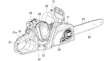
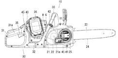
以下、本発明のチェーンソーの一実施形態を図面を参照して説明する。図1及び図2に示したように、チェーンソー10は、電動モータ21等を収容した本体ケーシング11と、本体ケーシング11の後部に取り付けたハンドル部30とを備えている。本体ケーシング11内の前後方向の中間部より前側には電動モータ21が設けられており、電動モータ21の駆動により回転する回転軸21aが本体ケーシング11の右側面中間部から外側に突出している。電動モータ21の回転軸21aにはスプロケット22が固定されており、スプロケット22は電動モータ21の駆動によって回転する。本体ケーシング11の右側面前部にはスプロケット22の前側にて前方に突出するガイドバー23が固定されており、ガイドバー23の外周部とスプロケット22との間にはソーチェーン24が回転可能に張設されている。本体ケーシング11の右側面前部にはスプロケットカバー25が設けられており、スプロケットカバー25は電動モータ21の回転軸21a、スプロケット22及びガイドバー23の基端部を覆っている。
Hereinafter, an embodiment of a chain saw of the present invention will be described with reference to the drawings. As shown in FIGS. 1 and 2, the
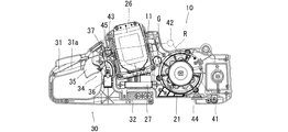
図1及び図2に示したように、本体ケーシング11の後部にはバッテリパック26が着脱可能に設けられている。この実施形態では、本体ケーシング11の後部にて左右両側部に左右一対のバッテリパック26が設けられている。これらバッテリパック26は電動モータ21に給電して、電動モータ21を駆動させるものである。図3に示したように、本体ケーシング11の下側後部には制御装置27が設けられており、制御装置27は電動モータ21の駆動を制御するものである。
As shown in FIGS. 1 and 2, a
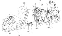
図1及び図2に示したように、ハンドル部30はチェーンソー10を使用する際に作業者が把持するものであり、本体ケーシング11の後部に防振的に取り付けられている。この実施形態では、ハンドル部30は本体ケーシング11の後部に設けられたリアハンドル(第1ハンドル)31と、本体ケーシング11の中間部より前側に設けられたフロントハンドル(第2ハンドル)33とを一体的に備えたハンドルユニットよりなる。リアハンドル31は側面から見たときに略環形状をしており、リアハンドル31の上部は作業者が把持するグリップ部31aとなっている。また、リアハンドル31の下部には前方に延びるベース部32が一体的に形成されており、ベース部32には上下を逆向きとした略U字形のフロントハンドル33が固定されている。
As shown in FIGS. 1 and 2, the
図3に示したように、リアハンドル31には操作部34が設けられており、操作部34はグリップ部31aに回動自在に指示されたトリガレバー35と、トリガレバー35の回動操作に応じた操作信号を出力する操作スイッチ部36とを備えている。操作スイッチ部36は信号線37により制御装置27に接続されており、操作スイッチ部36から出力される操作信号は信号線37によって制御装置27に送信される。信号線37の一端部は操作スイッチ部36に接続されており、信号線37はハンドル部30内から本体ケーシング11内に延び、信号線37の他端部は制御装置27に接続されている。この信号線37は操作スイッチ部36と制御装置27との間で長さが弛んだ状態で接続されている。
As shown in FIG. 3, the
本体ケーシング11とハンドル部30との間には防振部材41〜45が介装されており、本体ケーシング11にて電動モータ21の駆動及びソーチェーン24に回転によって生じる振動は防振部材41〜45によってハンドル部30に伝達されるのが抑制されている。防振部材41〜43はコイルスプリングを用いたものであり、防振部材41は本体ケーシング11の前側下部とフロントハンドル33の下端部との間に、防振部材42は本体ケーシング11の前後方向の中間部の上部とフロントハンドル33の右側上部との間に、防振部材43は本体ケーシング11の後側上部とリアハンドル31の前側上部との間に設けられている。コイルスプリングよりなる防振部材41〜43は左右方向を螺旋の進行方向として巻回されたものであり、左右方向に伸縮することで本体ケーシング11の左右方向の振動を吸収するとともに、上下及び前後に撓むことで本体ケーシングの上下及び前後の振動を吸収している。コイルスプリングよりなる防振部材43は軸線方向に延びる孔部を有しており、上述した信号線37はこの防振部材43の孔部を挿通されてハンドル部30内の操作スイッチ部36と本体ケーシング11内の制御装置27とに接続されている。
防振部材44,45は弾性力を有したゴム材を用いたものであり、防振部材44は本体ケーシング11の前側下部とフロントハンドル33の下端部との間に、防振部材45は本体ケーシング11の後側上部とリアハンドル31の前側上部との間に設けられている。
The
上記のように構成したチェーンソー10を木材の切断作業に使用するときには、作業者は例えば左手でフロントハンドル33を把持するとともに、右手でリアハンドル31のグリップ部31aを把持し、右手の人差し指をグリップ部31a側に引いてトリガレバー35を回動させると、操作スイッチ部36がトリガレバー35の操作に応じた操作信号を制御装置27に出力し、電動モータ21が制御装置27の制御に基づいて駆動する。ソーチェーン24は電動モータ21の駆動により回転するスプロケット22によってガイドバー23の外周部を回転し、作業者が両ハンドル31,33を操作してガイドバー23の外周部を回転するソーチェーン24を丸太等の木材の外周に押しつけることにより、丸太等の木材が切断される。
When the
このように構成したチェーンソー10においては、駆動源として電動モータ21を採用したことにより、エンジン等の内燃機関を駆動源としたよりも振動をある程度低減させることができる。しかし、駆動源として電動モータ21を用いたとしても、電動モータ21の駆動及びガイドバー23の外周部を回転するソーチェーン24による振動がハンドル31,33に伝達され、作業者がハンドル31,33を把持したときに振動によって疲れやすくなるおそれがあった。本発明のチェーンソー10においては、本体ケーシング11とハンドル部30との間に防振部材41〜45を介装したので、本体ケーシング11にて電動モータ21の駆動及びソーチェーン24がガイドバー23の外周部を回転することで生じる振動が防振部材41〜45によりハンドル部30に伝わりにくくなり、作業者が電動モータ21の駆動及びソーチェーン24の回転による振動によって疲れにくくなった。
In the chain saw 10 configured as described above, the use of the
また、この実施形態のチェーンソー10においては、本体ケーシング11には電動モータ21に給電するバッテリパック26が着脱可能に設けられている。このようにしたことで、振動源となる本体ケーシング11は重量物であるバッテリパック26が装着されることで振動が抑制されるようになり、作業者は振動による影響を一層受けないようになって疲れにくくなった。なお、バッテリパック26に代えて外部電源から電源コードにより電動モータ21に給電するようにしたときでも、バッテリパック26の重量による振動の抑制の作用効果を得ることができなくなるが、これ以外の作用効果を得ることができる。
Further, in the chain saw 10 of this embodiment, a
本発明のように、本体ケーシング11とハンドル部30との間に防振部材41〜45を介装してハンドル部30に振動が伝達するのを抑制したときには、本体ケーシング11に対してハンドル部30が安定せずにぐらつく新たな問題が生じるおそれがある。図2及び図3に示したように、このチェーンソー10では、本体ケーシング11とハンドル部30との間でチェーンソー10の重心位置Gを囲うように防振部材41〜45を配設した。このようにしたときには、本体ケーシング11に対して作業者が把持するハンドル部30がぐらつくことなく安定するようになり、ガイドバー23の外周部のソーチェーン24が傾いてぶれるのを防ぐことができた。
When the vibration is prevented from being transmitted to the
また、本体ケーシング11とハンドル部30とを分離し、本体ケーシング11とハンドル部30との間に防振部材41〜45を介装してハンドル部30に振動が伝達するのを抑制したときには、ハンドル部30の操作部34と本体ケーシング11内の制御装置27との間を接続する電気コードよりなる信号線37は本体ケーシング11とハンドル部30とが別々に変位するために断線する新たな問題が生じるおそれがある。図3に示したように、このチェーンソー10では、制御装置27と信号線37との接続部は本体ケーシング11内にて複数の防振部材41〜45により囲われた範囲Rに配置されるようにした。これにより、制御装置27と信号線37との接続部は防振部材41〜45により囲われた範囲Rにあるために振動による変位が少なく、制御装置27と信号線37との接続部が断線しにくくなった。
Further, when the
また、防振部材43は軸線方向の孔部を有したコイルスプリングよりなり、信号線37をハンドル部30からコイルスプリングよりなる防振部材43の孔部を挿通させて本体ケーシング11内に導出させた。このようにしたことで、信号線37はコイルスプリングよりなる防振部材43によって外側に露出しないようになり、信号線37が断線しにくくなった。なお、防振部材43をコイルスプリングに代えてゴム等の弾性力を有した材料を用いた筒形柔軟弾性部材を用いてもよい。さらに、信号線37は本体ケーシング11とハンドル部30と間にて弛みを持たせた状態で操作部34と制御装置27とを接続するようにした。このようにしたことで、チェーンソー10の使用時に本体ケーシング11が振動して、本体ケーシング11がハンドル部30に対して変位しても、信号線37は弛みによって断線しにくくなった。なお、信号線37は操作部34と制御装置27との経路にて10〜20%の範囲で弛むようにするのが好ましい。
Further, the
また、このチェーンソー10においては、ハンドル部30は一方と他方の各々の手で把持するリアハンドル(第1ハンドル)31とフロントハンドル(第2ハンドル)33を一体的に備えたハンドルユニットよりなり、本体ケーシング11とハンドルユニットとの間に防振部材41〜45を介装した。このようにしたことで、リアハンドル31とフロントハンドル33を1つのユニットとして本体ケーシング11に取り付けることができ、チェーンソー10の組み付け作業性を向上させることができた。なお、組み付け作業性が低下するが、リアハンドル31とフロントハンドル33とを別体として本体ケーシング11に防振部材を介装した状態で弾性的(防振的)に支持させてもよい。
In the chain saw 10, the
上記の実施形態のチェーンソーはいわゆるリアハンドルとフロントハンドル(サイドハンドルともいう)とを備えたリアハンドル型のチェーンソーであるが、本発明はこのリアハンドル型のチェーンソーに限られるものでなく、本体ケーシングの上部に設けたトップハンドルとフロントハンドル(サイドハンドルともいう)とを備えたトップハンドル型のチェーンソーにも適用されるものである。 The chain saw of the above embodiment is a rear handle type chain saw provided with a so-called rear handle and a front handle (also referred to as a side handle), but the present invention is not limited to this rear handle type chain saw, and is a main body casing. The present invention is also applicable to a top handle type chain saw provided with a top handle and a front handle (also referred to as a side handle) provided at the top of the machine.
上記の実施形態においては、防振部材41〜43はコイルスプリングを採用し、防振部材44,45は弾性力を有したゴム材を用いたものであるが、防振部材41〜45にはコイルスプリング及びゴム材等の弾性力を有した部材を適宜採用することができる。
In the above embodiment, the
10…チェーンソー、21…電動モータ、23…ガイドバー、24…ソーチェーン、26…バッテリパック、27…制御装置、30…ハンドル部、31…第1ハンドル(リアハンドル)、33…第2ハンドル(フロントハンドル)、34…操作部、37…信号線、41〜45…防振部材。
DESCRIPTION OF
Claims (7)
本体ケーシングの前部に前方に突出して設けたガイドバーと、
前記ガイドバーの外周部に回転可能に設けられ、前記電動モータの駆動によって前記ガイドバーの外周部を回転するソーチェーンと、
前記本体ケーシングに設けられて、作業者が把持するハンドル部とを備えたチェーンソーであって、
前記本体ケーシングと前記ハンドル部との間に防振部材を介装したことを特徴とするチェーンソー。 An electric motor provided in the body casing;
A guide bar that protrudes forward from the front of the main casing,
A saw chain rotatably provided on the outer periphery of the guide bar, and rotating the outer periphery of the guide bar by driving the electric motor;
A chain saw provided in the main body casing and provided with a handle portion gripped by an operator,
A chain saw characterized in that a vibration isolating member is interposed between the main body casing and the handle portion.
前記本体ケーシングには前記電動モータに給電するバッテリパックを着脱可能に設けたことを特徴とするチェーンソー。 The chainsaw according to claim 1,
A chain saw characterized in that a battery pack for supplying power to the electric motor is detachably provided in the main body casing.
前記本体ケーシングと前記ハンドル部との間で前記チェーンソーの重心位置を囲うように複数の前記防振部材を配設したことを特徴とするチェーンソー。 The chain saw according to claim 1 or 2,
A chain saw characterized in that a plurality of the vibration isolating members are disposed so as to surround the position of the center of gravity of the chain saw between the main body casing and the handle portion.
前記ハンドル部には前記電動モータを操作する操作信号を出力する操作部と、
前記本体ケーシングには前記操作部から出力される操作信号を送信する信号線に接続され、前記操作信号に基づいて前記電動モータの駆動を制御する制御装置とを備え、
前記制御装置と前記信号線との接続部は前記本体ケーシング内にて前記複数の防振部材により囲われた範囲に配置されたことを特徴とするチェーンソー。 The chainsaw according to claim 3,
An operation unit for outputting an operation signal for operating the electric motor to the handle unit;
The main body casing is connected to a signal line that transmits an operation signal output from the operation unit, and includes a control device that controls driving of the electric motor based on the operation signal,
A chain saw characterized in that a connecting portion between the control device and the signal line is arranged in a range surrounded by the plurality of vibration isolation members in the main body casing.
前記複数の防振部材の少なくとも1つは軸線方向に延びる孔部を有したコイルスプリングまたは筒形柔軟弾性部材を用いたものであり、
前記信号線を前記ハンドル部から前記防振部材の孔部を挿通させて前記本体ケーシング内に導出したことを特徴とするチェーンソー。 The chainsaw according to claim 4,
At least one of the plurality of vibration isolation members uses a coil spring or a cylindrical flexible elastic member having a hole extending in the axial direction,
A chain saw characterized in that the signal line is led from the handle portion through the hole portion of the vibration isolation member into the main casing.
前記信号線は前記本体ケーシングと前記ハンドル部との間にて弛みを持たせた状態で前記操作部と前記制御装置とを接続するようにしたことを特徴とするチェーンソー。 In the chainsaw according to claim 4 or 5,
A chain saw characterized in that the signal line connects the operation unit and the control device with a slack between the main body casing and the handle unit.
前記ハンドル部は一方と他方の各々の手で把持する第1及び第2ハンドルを一体的に備えたハンドルユニットよりなり、
前記本体ケーシングと前記ハンドルユニットとの間に前記防振部材を介装したことを特徴とするチェーンソー。 In the chainsaw according to any one of claims 1 to 6,
The handle portion is composed of a handle unit integrally including a first handle and a second handle gripped by one hand and the other hand,
A chain saw characterized in that the vibration isolating member is interposed between the main body casing and the handle unit.
Priority Applications (4)
| Application Number | Priority Date | Filing Date | Title |
|---|---|---|---|
| JP2016047429A JP6681226B2 (en) | 2016-03-10 | 2016-03-10 | Chainsaw |
| DE102016014489.0A DE102016014489A1 (en) | 2016-03-10 | 2016-12-06 | chainsaw |
| CN201710070968.5A CN107175723B (en) | 2016-03-10 | 2017-02-09 | Chain saw |
| US15/450,091 US11154943B2 (en) | 2016-03-10 | 2017-03-06 | Chainsaw |
Applications Claiming Priority (1)
| Application Number | Priority Date | Filing Date | Title |
|---|---|---|---|
| JP2016047429A JP6681226B2 (en) | 2016-03-10 | 2016-03-10 | Chainsaw |
Publications (2)
| Publication Number | Publication Date |
|---|---|
| JP2017159595A true JP2017159595A (en) | 2017-09-14 |
| JP6681226B2 JP6681226B2 (en) | 2020-04-15 |
Family
ID=59700298
Family Applications (1)
| Application Number | Title | Priority Date | Filing Date |
|---|---|---|---|
| JP2016047429A Active JP6681226B2 (en) | 2016-03-10 | 2016-03-10 | Chainsaw |
Country Status (4)
| Country | Link |
|---|---|
| US (1) | US11154943B2 (en) |
| JP (1) | JP6681226B2 (en) |
| CN (1) | CN107175723B (en) |
| DE (1) | DE102016014489A1 (en) |
Cited By (3)
| Publication number | Priority date | Publication date | Assignee | Title |
|---|---|---|---|---|
| WO2019039061A1 (en) | 2017-08-22 | 2019-02-28 | 株式会社ブリヂストン | Method for producing tire vulcanization mould, and tire vulcanization mould |
| JP2019072897A (en) * | 2017-10-13 | 2019-05-16 | 株式会社マキタ | Chain saw |
| JP2019123104A (en) * | 2018-01-12 | 2019-07-25 | 株式会社マキタ | Chain saw |
Families Citing this family (11)
| Publication number | Priority date | Publication date | Assignee | Title |
|---|---|---|---|---|
| JP6300271B2 (en) * | 2014-07-22 | 2018-03-28 | 株式会社マキタ | Chainsaw |
| USD860744S1 (en) * | 2016-04-08 | 2019-09-24 | Tti (Macao Commercial Offshore) Limited | Chainsaw |
| JP7245692B2 (en) * | 2019-03-26 | 2023-03-24 | 株式会社やまびこ | electric work machine |
| JP7348006B2 (en) * | 2019-09-12 | 2023-09-20 | 株式会社マキタ | power cutter |
| WO2021107827A1 (en) * | 2019-11-25 | 2021-06-03 | Husqvarna Ab | A hand-held electrically powered work tool |
| EP4670937A2 (en) * | 2019-11-25 | 2025-12-31 | Milwaukee Electric Tool Corporation | POWERED HAND CUTTING TOOL |
| US12064894B2 (en) | 2020-09-04 | 2024-08-20 | Milwaukee Electric Tool Corporation | Chainsaw |
| SE545104C2 (en) * | 2021-04-28 | 2023-04-04 | Husqvarna Ab | Handheld power tool with an angled separation plane |
| CN115722728B (en) * | 2021-08-25 | 2025-12-05 | 南京泉峰科技有限公司 | Power tools, single hand saw |
| USD1118291S1 (en) * | 2021-09-08 | 2026-03-17 | Husqvarna Ab | Chainsaw |
| USD1051691S1 (en) * | 2024-02-27 | 2024-11-19 | Minli Liao | Chainsaw |
Citations (16)
| Publication number | Priority date | Publication date | Assignee | Title |
|---|---|---|---|---|
| JPS4884395A (en) * | 1972-01-26 | 1973-11-09 | ||
| JPS52130124A (en) * | 1976-04-23 | 1977-11-01 | Sakura Denki Kk | Concrete oscillator |
| JPS5899001U (en) * | 1981-12-25 | 1983-07-05 | 川崎重工業株式会社 | Vibration isolation material with conductive wire |
| JPS60146867U (en) * | 1984-03-09 | 1985-09-30 | 本田技研工業株式会社 | mercury electricity meter |
| JPH0625288Y2 (en) * | 1987-03-18 | 1994-07-06 | 株式会社共立 | Anti-vibration mounting device for chain handle |
| JPH09109101A (en) * | 1995-08-21 | 1997-04-28 | Andreas Stihl:Fa | Anti-vibrational element between driving machine unit and grip unit |
| JP2552060Y2 (en) * | 1991-09-02 | 1997-10-27 | 新ダイワ工業株式会社 | Chainsaw front handle mounting structure |
| JPH1080822A (en) * | 1996-08-01 | 1998-03-31 | Andreas Stihl:Fa | Power chain saw |
| JP2838038B2 (en) * | 1993-06-30 | 1998-12-16 | アンドレアス・シユテイール | Synthetic grip for hand-operated power chainsaw |
| JP3029622B2 (en) * | 1988-04-08 | 2000-04-04 | アンドレアス シュティール | Curved grip for portable power chainsaw |
| JP2001035062A (en) * | 1999-07-21 | 2001-02-09 | Minolta Co Ltd | Recording device |
| JP2001205602A (en) * | 2000-01-27 | 2001-07-31 | Kioritz Corp | Portable power working machine |
| JP2003110007A (en) * | 2001-10-01 | 2003-04-11 | Nikon Corp | Stage device, holding device, and exposure device |
| US8060986B1 (en) * | 2010-08-03 | 2011-11-22 | Green Donald L | Chain saw handle apparatus |
| JP2015523226A (en) * | 2012-06-12 | 2015-08-13 | フスクバルナ アクティエボラーグ | Electric cutting system |
| JP2016022675A (en) * | 2014-07-22 | 2016-02-08 | 株式会社マキタ | Chainsaw |
Family Cites Families (14)
| Publication number | Priority date | Publication date | Assignee | Title |
|---|---|---|---|---|
| US2765822A (en) * | 1953-11-06 | 1956-10-09 | John W Smith | Chain saw cart |
| US4138812A (en) * | 1977-10-14 | 1979-02-13 | Mcculloch Corporation | Vibration isolation system for chain saw structures |
| US4407068A (en) * | 1982-03-15 | 1983-10-04 | Wilson Timothy W | Hair cutter with vacuum |
| US4727828A (en) * | 1985-03-29 | 1988-03-01 | Komatsu Zenoah Company | Portable engine unit |
| DE3935361C2 (en) * | 1989-10-24 | 1998-12-24 | Stihl Maschf Andreas | Tool such as a chainsaw or the like, especially a one-hand chain saw |
| CN2475540Y (en) * | 2001-04-26 | 2002-02-06 | 杨培华 | Cutting chain saw for internal wall of building |
| US6443753B1 (en) * | 2001-06-04 | 2002-09-03 | Black & Decker Inc. | Power tool cord retainer |
| DE102005036885B4 (en) * | 2005-08-05 | 2015-03-19 | Andreas Stihl Ag & Co. Kg | Hand-held implement |
| JP2007176128A (en) * | 2005-12-28 | 2007-07-12 | Komatsu Zenoah Co | Chain saw |
| DE102007022115B4 (en) * | 2007-05-11 | 2024-11-14 | Andreas Stihl Ag & Co. Kg | hand-held chainsaw |
| EP2433767B1 (en) * | 2009-05-11 | 2017-01-11 | Husqvarna AB | Chainsaw arrangement |
| JP5598213B2 (en) * | 2010-09-29 | 2014-10-01 | 日立工機株式会社 | Portable work machine |
| JP6032400B2 (en) | 2012-08-15 | 2016-11-30 | 日立工機株式会社 | Chainsaw |
| JP2015044293A (en) | 2013-08-27 | 2015-03-12 | 株式会社マキタ | Chain saw |
-
2016
- 2016-03-10 JP JP2016047429A patent/JP6681226B2/en active Active
- 2016-12-06 DE DE102016014489.0A patent/DE102016014489A1/en active Pending
-
2017
- 2017-02-09 CN CN201710070968.5A patent/CN107175723B/en active Active
- 2017-03-06 US US15/450,091 patent/US11154943B2/en active Active
Patent Citations (16)
| Publication number | Priority date | Publication date | Assignee | Title |
|---|---|---|---|---|
| JPS4884395A (en) * | 1972-01-26 | 1973-11-09 | ||
| JPS52130124A (en) * | 1976-04-23 | 1977-11-01 | Sakura Denki Kk | Concrete oscillator |
| JPS5899001U (en) * | 1981-12-25 | 1983-07-05 | 川崎重工業株式会社 | Vibration isolation material with conductive wire |
| JPS60146867U (en) * | 1984-03-09 | 1985-09-30 | 本田技研工業株式会社 | mercury electricity meter |
| JPH0625288Y2 (en) * | 1987-03-18 | 1994-07-06 | 株式会社共立 | Anti-vibration mounting device for chain handle |
| JP3029622B2 (en) * | 1988-04-08 | 2000-04-04 | アンドレアス シュティール | Curved grip for portable power chainsaw |
| JP2552060Y2 (en) * | 1991-09-02 | 1997-10-27 | 新ダイワ工業株式会社 | Chainsaw front handle mounting structure |
| JP2838038B2 (en) * | 1993-06-30 | 1998-12-16 | アンドレアス・シユテイール | Synthetic grip for hand-operated power chainsaw |
| JPH09109101A (en) * | 1995-08-21 | 1997-04-28 | Andreas Stihl:Fa | Anti-vibrational element between driving machine unit and grip unit |
| JPH1080822A (en) * | 1996-08-01 | 1998-03-31 | Andreas Stihl:Fa | Power chain saw |
| JP2001035062A (en) * | 1999-07-21 | 2001-02-09 | Minolta Co Ltd | Recording device |
| JP2001205602A (en) * | 2000-01-27 | 2001-07-31 | Kioritz Corp | Portable power working machine |
| JP2003110007A (en) * | 2001-10-01 | 2003-04-11 | Nikon Corp | Stage device, holding device, and exposure device |
| US8060986B1 (en) * | 2010-08-03 | 2011-11-22 | Green Donald L | Chain saw handle apparatus |
| JP2015523226A (en) * | 2012-06-12 | 2015-08-13 | フスクバルナ アクティエボラーグ | Electric cutting system |
| JP2016022675A (en) * | 2014-07-22 | 2016-02-08 | 株式会社マキタ | Chainsaw |
Cited By (4)
| Publication number | Priority date | Publication date | Assignee | Title |
|---|---|---|---|---|
| WO2019039061A1 (en) | 2017-08-22 | 2019-02-28 | 株式会社ブリヂストン | Method for producing tire vulcanization mould, and tire vulcanization mould |
| JP2019072897A (en) * | 2017-10-13 | 2019-05-16 | 株式会社マキタ | Chain saw |
| JP2019123104A (en) * | 2018-01-12 | 2019-07-25 | 株式会社マキタ | Chain saw |
| JP6999429B2 (en) | 2018-01-12 | 2022-01-18 | 株式会社マキタ | Chainsaw |
Also Published As
| Publication number | Publication date |
|---|---|
| CN107175723A (en) | 2017-09-19 |
| CN107175723B (en) | 2021-07-09 |
| JP6681226B2 (en) | 2020-04-15 |
| US20170259359A1 (en) | 2017-09-14 |
| DE102016014489A1 (en) | 2017-09-14 |
| US11154943B2 (en) | 2021-10-26 |
Similar Documents
| Publication | Publication Date | Title |
|---|---|---|
| JP6681226B2 (en) | Chainsaw | |
| JP6615648B2 (en) | Chainsaw | |
| JP5928720B2 (en) | Electric working machine | |
| US20140007436A1 (en) | Power tool including an anti-vibration handle | |
| CN101203361B (en) | Chain saw | |
| JP5751772B2 (en) | Anti-vibration mechanism of handle in portable type brush cutter | |
| US11052529B2 (en) | Electrical work apparatus having vibration decoupling | |
| JP4491320B2 (en) | Brush cutter | |
| US11540442B2 (en) | Working machine | |
| JP4071413B2 (en) | Portable power work machine | |
| JP6266304B2 (en) | Reciprocating cutting tool | |
| WO2015107731A1 (en) | Work machine | |
| JP2006311828A (en) | Brush cutter | |
| JP2010274385A (en) | Electric tool | |
| JP7133365B2 (en) | chainsaw | |
| JP2014161269A (en) | Knapsack bush cutter | |
| JP6076165B2 (en) | Vibration isolator for portable work machines | |
| JP4606244B2 (en) | Brush cutter | |
| JP2006042724A (en) | Vibration proofing structure of power implement | |
| JP6697895B2 (en) | Work tools | |
| JP2014117263A (en) | Bush cutter | |
| JP2025015156A (en) | System containing motor unit | |
| JP6081384B2 (en) | Working machine | |
| JP3179319U (en) | Mower and handle for mower | |
| JP5830046B2 (en) | Back working machine |
Legal Events
| Date | Code | Title | Description |
|---|---|---|---|
| RD02 | Notification of acceptance of power of attorney |
Free format text: JAPANESE INTERMEDIATE CODE: A7422 Effective date: 20180412 |
|
| RD04 | Notification of resignation of power of attorney |
Free format text: JAPANESE INTERMEDIATE CODE: A7424 Effective date: 20180416 |
|
| A621 | Written request for application examination |
Free format text: JAPANESE INTERMEDIATE CODE: A621 Effective date: 20181218 |
|
| A977 | Report on retrieval |
Free format text: JAPANESE INTERMEDIATE CODE: A971007 Effective date: 20191017 |
|
| A131 | Notification of reasons for refusal |
Free format text: JAPANESE INTERMEDIATE CODE: A131 Effective date: 20191029 |
|
| A521 | Request for written amendment filed |
Free format text: JAPANESE INTERMEDIATE CODE: A523 Effective date: 20191220 |
|
| A131 | Notification of reasons for refusal |
Free format text: JAPANESE INTERMEDIATE CODE: A131 Effective date: 20200114 |
|
| A521 | Request for written amendment filed |
Free format text: JAPANESE INTERMEDIATE CODE: A523 Effective date: 20200309 |
|
| TRDD | Decision of grant or rejection written | ||
| A01 | Written decision to grant a patent or to grant a registration (utility model) |
Free format text: JAPANESE INTERMEDIATE CODE: A01 Effective date: 20200317 |
|
| A61 | First payment of annual fees (during grant procedure) |
Free format text: JAPANESE INTERMEDIATE CODE: A61 Effective date: 20200323 |
|
| R150 | Certificate of patent or registration of utility model |
Ref document number: 6681226 Country of ref document: JP Free format text: JAPANESE INTERMEDIATE CODE: R150 |
|
| R250 | Receipt of annual fees |
Free format text: JAPANESE INTERMEDIATE CODE: R250 |
|
| R250 | Receipt of annual fees |
Free format text: JAPANESE INTERMEDIATE CODE: R250 |
|
| R250 | Receipt of annual fees |
Free format text: JAPANESE INTERMEDIATE CODE: R250 |
|
| R250 | Receipt of annual fees |
Free format text: JAPANESE INTERMEDIATE CODE: R250 |