JP2017159656A - Trimmer implement - Google Patents
Trimmer implement Download PDFInfo
- Publication number
- JP2017159656A JP2017159656A JP2017050544A JP2017050544A JP2017159656A JP 2017159656 A JP2017159656 A JP 2017159656A JP 2017050544 A JP2017050544 A JP 2017050544A JP 2017050544 A JP2017050544 A JP 2017050544A JP 2017159656 A JP2017159656 A JP 2017159656A
- Authority
- JP
- Japan
- Prior art keywords
- trimmer
- piece
- holding base
- plate
- guide body
- Prior art date
- Legal status (The legal status is an assumption and is not a legal conclusion. Google has not performed a legal analysis and makes no representation as to the accuracy of the status listed.)
- Granted
Links
Images






Landscapes
- Dovetailed Work, And Nailing Machines And Stapling Machines For Wood (AREA)
Abstract
Description
本発明は、安全なトリマー用の治具であって木板を円弧上に加工するものに関するものである。 The present invention relates to a safe trimmer jig for processing a wooden board on an arc.
一般的に使用されているトリマー(例えば特開平10−225910号公報に記載の物)はそのままで使用すると、トリマーのビットが木のかたい部分に当たった場合などにビットが跳ね上がったり、横滑りして危険な場合がある。 If a trimmer that is generally used (for example, the one described in Japanese Patent Application Laid-Open No. 10-225910) is used as it is, the bit jumps up or skids when the trimmer bit hits a hard part of a tree. It can be dangerous.
そこで、本発明は、新規なトリマー用治具を発明することにより、トリマーをより安全に、かつ木板を円弧状に加工できるものを提供することを目的とする。 Therefore, an object of the present invention is to provide a new trimmer jig that can process a trimmer more safely and can process a wooden board into an arc shape.
本発明のトリマー治具は、トリマー本体を上下動する外筒の下端に設けられたベースプレートを保持する保持ベースと、この保持ベースに設けられた前記トリマー本体のビットを挿入することができる透孔と、前記ベースプレートの側壁の一端を前記保持ベース上でその一部に当てる第一の当接片と、この第一の当接片と対抗して設けられ前記ベースプレートの側壁の他端に当てる第二の当接片と、上記透孔において前記保持ベースの中央に向かって伸びる突出片とを設けたことを特徴とする。
また、本発明のトリマー治具は、トリマー本体を上下動する外筒の下端に設けられたベースプレートを保持する保持ベースと、この保持ベースに一端が固定される長尺のガイド体と、このガイド体を包むように設けられたスライド体と、このスライド体の底面から前記保持ベースの中央に向かって伸びる突出片と、前記スライド体を前記ガイド体に固定自在とする固定部材とを備え、この突出片には裏面先端部より突出して中心軸が設けられ、前記保持ベースに、前記トリマー本体のビットを挿入することができる透孔と、前記ガイド体を固定すると共に前記ベースプレートを前記保持ベース上で当てる第一の当接片と、この第一の当接片と対抗して設けられ前記ベースプレートの側壁を当てる第二の当接片とを設けたことを特徴とする。The trimmer jig of the present invention has a holding base that holds a base plate provided at the lower end of an outer cylinder that moves up and down the trimmer main body, and a through hole into which the bit of the trimmer main body provided in the holding base can be inserted. And a first abutting piece that applies one end of the side wall of the base plate to a part of the holding base, and a first abutting piece provided opposite to the first abutting piece and applied to the other end of the side wall of the base plate. Two contact pieces and a protruding piece extending toward the center of the holding base in the through hole are provided.
The trimmer jig of the present invention includes a holding base that holds a base plate provided at the lower end of an outer cylinder that moves up and down the trimmer main body, a long guide body having one end fixed to the holding base, and the guide A slide body provided to wrap the body, a projecting piece extending from the bottom surface of the slide body toward the center of the holding base, and a fixing member that can fix the slide body to the guide body. The piece is provided with a central axis that protrudes from the tip of the back surface, and a through hole into which the bit of the trimmer main body can be inserted into the holding base, and the guide body is fixed and the base plate is fixed on the holding base. A first abutting piece to be contacted and a second abutting piece provided to face the first abutting piece and against the side wall of the base plate are provided.
また、上記対抗する方向と直行する方向に前記保持ベースが移動しないようにするストッパーを設けることを特徴とする。
また、前記ストッパーとして前記第一の当接片と第二の当接片を結ぶ線に直行した線上に第三の当接片と第四の当接片を設けたことを特徴とする。
また、前記ストッパーとして前記外筒2に設けられている結合板と第二の当接片とにネジ穴を設け、このネジ穴にネジを螺合するようにしたことを特徴とする。Further, a stopper for preventing the holding base from moving in a direction perpendicular to the opposing direction is provided.
In addition, a third contact piece and a fourth contact piece are provided on the line orthogonal to the line connecting the first contact piece and the second contact piece as the stopper.
Further, a screw hole is provided in the coupling plate provided in the
また、前記ガイド体の表面に目安となるメモリを設けたことを特徴とする。
また、前記突出片が入る透孔と前記ビットが入る透孔とを連通する透孔としたことを特徴とする。
また、前記固定部材を前記スライド体に設けたネジ穴とこれに螺合するネジとしたことを特徴とする。
また、前記スライド体をコ字状体とこのコ字状体を覆う底板とし、前記突出片をこの底板と一体成型したことを特徴とする。In addition, a memory serving as a guide is provided on the surface of the guide body.
In addition, the through hole into which the projecting piece enters and the through hole into which the bit enters are formed as a through hole.
Further, the fixing member is a screw hole provided in the slide body and a screw screwed into the screw hole.
Further, the slide body is a U-shaped body and a bottom plate that covers the U-shaped body, and the protruding piece is integrally molded with the bottom plate.
また、前記突出片は前記保持ベースの端面から始まり前記透孔の中央に向かう長さであることを特徴とする。
また、前記保持ベースの後端部に両端に開口部を有するコ字状の制御板を取付け、前記突出片には保持ベースの後端方向の端部より上方に立上部を設け、続いて折返部を設けるとともに、前記突出片を前記開口部より前記制御板に挿入状態とし、前記制御板に補強用の箱体を設け、前記折返部を前記制御板に固定可能としたことを特徴とする。
また、前記折返部を二股に分離し、二股の間に制御板の上方から差し込まれたネジを挿通し、前記折返部の裏面でナットと結合したことを特徴とする。The protruding piece has a length starting from an end surface of the holding base and extending toward the center of the through hole.
Also, a U-shaped control plate having openings at both ends is attached to the rear end of the holding base, and a raised portion is provided above the end of the holding base in the rear end direction, followed by folding. A protruding box is inserted into the control plate from the opening, a reinforcing box is provided on the control plate, and the folded portion can be fixed to the control plate. .
Further, the folded portion is divided into two forks, and a screw inserted from above the control plate is inserted between the forks, and is connected to a nut on the back surface of the folded portion.
また、前記保持ベースの後端部に両端に開口部を有するコ字状の制御板を取付け、長尺のガイド体を設け、このガイド体を包むようにスライド体を設け、このスライド体に前記突出片を設け、前記ガイド体の端部を前記制御板の開口部より挿入状態とし、前記突出片と前記ガイド体を結合したことを特徴とする。 In addition, a U-shaped control plate having openings at both ends is attached to the rear end of the holding base, a long guide body is provided, a slide body is provided so as to wrap the guide body, and the protrusion is projected on the slide body. A piece is provided, the end of the guide body is inserted from the opening of the control plate, and the protruding piece and the guide body are coupled.
また、前記ガイド体と前記制御板の天板との間に隙間を設け、前記制御板の内部の一部に前記隙間に向かって開口する凹部を形成し、この凹部に前記制御板の側部から突出した突片を挿入し、前記隙間をなくすように前記ガイド体を持ち上げることを特徴とする。
さらに、前記スライド体にメモリと前記ガイド体に前記スライド体を固定する固定部材を設け、このスライド体に当接可能な回動板を設け、この回動板を前記ガイド体に固定することが出来る取付台に回動自在とし、前記スライド体と当接する前記回動体の端部の径を少しずつ異ならせたことを特徴とする。Further, a gap is provided between the guide body and the top plate of the control plate, and a recess opening toward the gap is formed in a part of the inside of the control plate, and a side portion of the control plate is formed in the recess. The projecting piece protruding from is inserted, and the guide body is lifted so as to eliminate the gap.
Furthermore, a fixing member for fixing the slide body to the memory and the guide body is provided on the slide body, a rotating plate capable of contacting the slide body is provided, and the rotating plate is fixed to the guide body. The mounting base can be freely rotated, and the diameter of the end of the rotating body that contacts the slide body is gradually changed.
以上のように、本発明のトリマー治具はトリマーを安全に固定することができる。しかも、中心軸をビットの近くまで位置させることができるので、極めて小さな円弧を作成することもできる。特にビットの近くに壁などの邪魔があっても加工できる。大きな円弧を作成することができるのは勿論である。メモリを用いて円弧の径を定める場合、微調整機構を用いて微調整できる。また、トリマーを何時でも正しい位置に固定できる。 As described above, the trimmer jig of the present invention can fix the trimmer safely. In addition, since the central axis can be located close to the bit, an extremely small arc can be created. It can be processed even if there are obstacles such as walls near the bit. Of course, a large arc can be created. When the diameter of the arc is determined using the memory, it can be finely adjusted using a fine adjustment mechanism. Also, the trimmer can be fixed at the correct position at any time.
以下、本発明の実施の形態について図面とともに説明する。
図1、図2、図3に示すように、トリマー本体1をスライドして上下動する外筒2の下端に設けられたベースプレート3を保持する保持ベース4を設ける。外筒2はトリマー本体にネジ5を支片6のネジ穴7に挿入することにより固定される。外筒2、及びベースプレート3は透明な樹脂で作られていることが多い。また、保持ベースは鉄やアルミニュウム、合成樹脂等で作られる。Hereinafter, embodiments of the present invention will be described with reference to the drawings.
As shown in FIGS. 1, 2, and 3, a
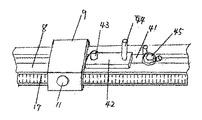
ガイド体8が設けられ、このガイド体8を包むように設けられたスライド体9と、このスライド体9の底面から保持ベース4の中央に向かって伸びる突出片10と、スライド体9をガイド体8に固定自在とする固定部材とを備える。固定部材はネジ11とネジ穴12により構成される。他の手段でも良い。後で説明するが、保持ベース4には第一の当接片15が設けられており。この当接片15にネジによりガイド体8が片持ち梁状に取り付けられる。 A
上記突出片10には裏面先端部より突出して中心軸13が設けられる。この中心軸13は例えば鉄製の突出片10に穴を設け、ここに鉄製の中心軸13を挿入し溶接或いは、かしめをして固定する。他の手段でも良い。
保持ベース4に突出片10を挿入することができる透孔14を設ける。この透孔14は、トリマー本体1のビットを挿入することができるまで延長する。または、透孔14を短くし、トリマー1のビット18を独立して挿入できる透孔を設けても良い。共通の透孔にする方が加工する径がより小さくなって良い。The
A through
ガイド体8を固定すると共にベースプレート3を前記保持ベース4上で当てる第一の当接片15と、この第一の当接片15と対抗して設けられ前記ベースプレート3の側壁を当てる第二の当接片16とを設ける。上記対抗は例えば第一の当接片15に対し二つの片をハの字状にしても良く結果として対抗していればよい。17はガイド体8に設けたメモリである。 A first abutting
まず、メモリ17を用いて大よそのカーブの径を設定し、ネジ11をネジ穴12にねじ込んでスライド体9をガイド体8に固定する。次に、被加工物である木片の中心孔に中心軸13を嵌入する。次に、トリマーのベースプレート3を保持ベース4上に置く。このとき第一の当接片15と第二の当接片16がトリマーのベースプレート3の側壁に当たり固定される。同時に第三の当接片24と第四の当接片25もベースプレート3の側壁に当たり固定される。
トリマーをもって被加工物を円弧状に加工する。First, the approximate curve diameter is set using the
A workpiece is processed into a circular arc shape with a trimmer.
図4は他の実施例である。第1図例ではトリマーは上方へ移動する。この例ではトリマーを上方に移動させることはない。外筒2には他の物を結合する結合板19が設けられている。この結合板19には一体に突出片21が設けられている。第二の当接片16にこの突出片21を挿入する凹み20を設ける。さらに第二の当接片16と結合板19に連通してネジ穴22を設け、このネジ穴にネジ23を螺合する。 FIG. 4 shows another embodiment. In the example of FIG. 1, the trimmer moves upward. In this example, the trimmer is not moved upward. The
すると、外筒2は第二の当接片16にネジ23によりしっかりと固定され、上方向は勿論のこと左右方向にも移動することはない。このとき第三の当接片24、第四の当接片25は設ける必要はなくなる。突出片21は他の物結合のため突出板19に設けられているが、結合板19側の問題であり、突出片21のない結合板19であれば凹み20を設ける必要はない。 Then, the
次に、他の実施例について説明する。説明は図5〜図17までであるが、図5〜図17に示す図番は図1〜図4の図番と同じ役割のものは同じ番号を付しておく。
第1図〜第4図に示すものは半径の大きな板体に穴をあける場合や、小さい半径の板体に穴をあける場合であって、あける穴の周囲に邪魔者がないときは良いが、あける穴の周囲に壁等の邪魔者が存在すると、ガイド体8が邪魔になり穴をあけることが出来ない。そこで、この欠点を解消するために設けられたものが図5〜図7に示すものである。Next, another embodiment will be described. The description is from FIG. 5 to FIG. 17, and the figure numbers shown in FIG. 5 to FIG. 17 have the same numbers as those in FIG. 1 to FIG.
1 to 4 show a case where a hole is made in a plate having a large radius or a case where a hole is made in a plate having a small radius, and there is no obstacle around the hole to be opened. If there is an obstacle such as a wall around the hole to be opened, the
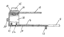
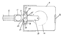
図5〜図7に示すように、保持ベース4の透孔14に臨むように突出片10が設けられている。この突出片10は薄い鉄板(アルミの板でも可能かも)で作られており、全体としてコ字状をしている。保持ベース4の後端には突出片10が入って、かつ出る方向に開口部26を有する基本コ字状であり下端両側に張り出し部27,28を持つ制御板29が取り付けられている。 As shown in FIGS. 5 to 7, the protruding
突出片10は薄い鉄板で作られているので、弱い。そこでコ字状をしている中に箱体30を取り付けて強度を増すようにする。底辺のビス31,32、側面のネジ33,34によって取り付ける。制御板29の上端には大きいネジ35が挿入されておりナット36が螺合している。ネジ35の下端は箱体30の頭部に当たっていない。突出片10の上辺はネジ35を避けるため二股に分かれており、ネジ35とナット36により締めつけられ、突出片10は動くことが出来ない。ネジ35を緩めると突出片10は左右に動かすことが出来る。制御板29の両立上部側壁には突出部37,38が溶接されており、突出部37,38の先端に設けられた径の小さい突片は制御板29の立上部を貫通しているが、その先端は箱体30に当たっていない。 Since the protruding
突出片10の下辺先端部には図12に示す中心軸13が溶接により取り付けられている。溶接のため複雑な形状をしているが、図7では簡略化して書いてある。
次に、この装置の使い方について説明する。ネジ35を緩め、突出片10を左右に動かし、加工する木板の穴に中心軸13を挿入する。中心軸13が右方にあるほど加工半径は短くなる。この装置には長尺のガイド体8がない為邪魔にならず、加工する木板の周りに壁があっても、突出片10が最左端に有るときが最大で径がそれより短ければ使用できる。A
Next, how to use this apparatus will be described. The
次に、主に図10、図11を用いて長尺のガイド体8を用いる場合について説明する。まず、図5、図6、図7における突出片10を保持ベース4より引き抜く。次にガイド体8にスライド体9をスライド自在に挿入しておく。ガイド体8の端面は図14に示すような複雑な形状をしており、各社色々な形状のものを保有しており、これを兼用している。図10、図11はスライド体9を最右端に位置させた状態を示している。 Next, the case where the
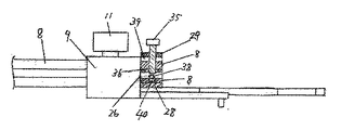
スライド体9の底面は突出片10(図5、図6、図7に示すものとは異なるが同じ図番を付しておく。)を設けておく。具体的にはスライド体9の底面が突出片10の一部をなしているよう構成する。従がって突出片10はスライド体9とともに移動する。スライド体9の天板に設けられたネジ11を捻じ込むことによりスライド体9をガイド体8に固定する。位置決めはメモリ17によって行う。スライド体9を通り抜けたガイド体8は制御板29の開口部26より入る。このとき制御板29の内部に突出しているネジ等はガイド体8の空間部に入り、邪魔をすることはない。始めガイド体8と制御板29の間には図11、図9に示すように少し隙間39が設けられている。後でガイド体8が持ち上げられ、隙間39はなくなる。 The bottom surface of the
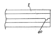
図8、図9、図11に示すようにガイド体8の先端部には凹部40が設けられている。この凹部40は隙間39にその開口部が向けられるようになっている。そして、この凹部40には突出部37、38の突片が入ることになる。隙間39にはナット36が設けられており、ここにネジ35が螺合する。突出片10の厚みは図7に示すものより厚くてよく、保持ベース4より下方にある。ネジ35を締めることにより隙間39が無くなり、突出片10は保持ベース4と面一になる。 As shown in FIGS. 8, 9, and 11, a
次に、この装置の動きについて説明する。まず、図5、図6、図7における突出片10を保持ベース4より引き抜く。次にガイド体8にスライド体9をスライド自在に挿入する。スライド体9をメモリ17を用いて所定の場所に位置決めし、ネジ11を締めつけて固定する。ガイド体8を制御板29の開口部26から挿入し、凹部40に突出部37,38の先端部を入れる。次にネジ35をねじることにより隙間39をなくし、ガイド体8、スライド体9、突出片10を上方に持ち上げる。ガイド体8を用いるので、半径の大きな加工が出来る。 Next, the movement of this apparatus will be described. First, the protruding
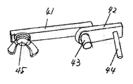
次に、この長尺のガイド体8に用いることが出来る微調整機構について説明する。図15に示すように取付台41の一端に回動板42をネジ43によって回動自在とする。回動板42の一端は湾曲しており徐々に径が大きくなるように構成されている。回動板42の他端には取っ手44が取り付けられている。取付台41の他端に蝶ボルト45が取り付けられている。図13に示すように、ガイド体8の側面の溝から取付台41を挿入し、蝶ボルト45でガイド体8に固定できるようにする。 Next, a fine adjustment mechanism that can be used for the
ガイド体8の上面に設けたメモリ17によって、所定の位置決めをし、スライド体9のネジ11を締めつけてスライド体9をガイド体8にほぼ固定する。回動板42の先端をスライド体9に当て、蝶ボルト45を締めてガイド体8に固定する。さらに、取っ手44を持って回動板42を少し回動すると、回動板42の端部の径で当たっているスライド体9を少し移動させることが出来る。ネジ11を締めてこれで微調整が完成する。図1の場合にも応用できることは勿論である。 The
次に、図16、図17を用いて、上下動するトリマー本体1が最初に定めた位置に次の作業時にも来てトリマー本体1のビット18の先端が一定深さになる機構について説明する。
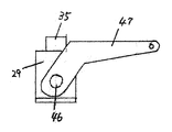
図16、図17に示すように、制御板29に設けた突出部37、38の頭部にネジ46を設け、その間にレバ―47を取り付け、さらに一対のレバー47を連結体50により連結する。レバ―47を回動させることにより、トリマー本体1の下端周縁に連結体50を当てることが出来、先に定めた位置にトリマー本体1を位置決めすることが出来る。図1の場合にも応用できることは勿論である。Next, with reference to FIGS. 16 and 17, a mechanism will be described in which the trimmer body 1 that moves up and down comes to the initially determined position during the next operation and the tip of the
As shown in FIGS. 16 and 17, screws 46 are provided on the heads of the
図5、図10において、トリマー本体1の外筒2の下端に設けられたベースプレート3を保持ベース4に固定するため、ベースプレート3の一端を制御板29の端部(第一の当接片15)に当てベースプレート3の他端を第ニの当接片16に当てる。そして第ニの当接片16にネジ23(図5、図10では図示していない)で実質的に外筒2に結合する。この結合だけで十分であり、第一の当接片15の距離が小さくても問題はない。第三の当接片24、第四の当接片25を設けるとさらに良い。 5 and 10, in order to fix the base plate 3 provided at the lower end of the
図5、図6、図7に示す短い径の孔を木に開けるときに適した構造物の場合、突出片10の長さは(立上部や折返部を含まない。)保持ベース4から始まり透孔14の中央に向かう長さである。図5、図6、図7では突出片10が薄い為折返部のある形状にしたが、厚い鉄板の場合は立上部や折返部は不要であり、側方からストッパーを設ければよい。ただし、加工が困難で高く付く欠点がある。 In the case of a structure suitable for drilling a short-diameter hole shown in FIGS. 5, 6, and 7, the length of the protruding
以上のように、本発明のトリマー治具はトリマーを安全に固定することができる。しかも、中心軸をビットの近くまで位置させることができるので、極めて小さな円弧を作成することもできる。大きな円弧を作成することができるのは勿論である。 As described above, the trimmer jig of the present invention can fix the trimmer safely. In addition, since the central axis can be located close to the bit, an extremely small arc can be created. Of course, a large arc can be created.
本発明は、あらゆるトリマーで利用することができ安全性の高いものである。 The present invention can be used with any trimmer and is highly safe.
1:トリマー本体
2:外筒
3:ベースプレート
4:保持ベース
5:ネジ
6:支片
7:ネジ穴
8:ガイド体
9:スライド体
10:突出片
11:ネジ
12:ネジ穴
13:中心軸
14:透孔
15:第一の当接片
16:第二の当接片
17:メモリ
18:ビット
19:結合板
20:凹み
21:突出片
22:ネジ穴
23:ネジ
24:第三の当接片
25:第四の当接片
26:開口部
29:制御板
30:箱体
31、32,33,34:ネジ
35:ネジ
36:ナット
37,38:突出部
39:隙間
40:凹部
41:取付台
42:回動板
43:ネジ
44:取っ手
45:蝶ボルト
46:ネジ
47:レバー
50:連結体1: Trimmer body 2: Outer cylinder 3: Base plate 4: Holding base 5: Screw 6: Support piece 7: Screw hole 8: Guide body 9: Slide body 10: Projection piece 11: Screw 12: Screw hole 13: Center shaft 14 : Through hole 15: First contact piece 16: Second contact piece 17: Memory 18: Bit 19: Connecting plate 20: Recess 21: Projection piece 22: Screw hole 23: Screw 24: Third contact Piece 25: Fourth contact piece 26: Opening portion 29: Control plate 30:
Claims (15)
Applications Claiming Priority (2)
| Application Number | Priority Date | Filing Date | Title |
|---|---|---|---|
| JP2016057605 | 2016-03-03 | ||
| JP2016057605 | 2016-03-03 |
Publications (2)
| Publication Number | Publication Date |
|---|---|
| JP2017159656A true JP2017159656A (en) | 2017-09-14 |
| JP6933852B2 JP6933852B2 (en) | 2021-09-08 |
Family
ID=59854757
Family Applications (1)
| Application Number | Title | Priority Date | Filing Date |
|---|---|---|---|
| JP2017050544A Active JP6933852B2 (en) | 2016-03-03 | 2017-02-27 | Trimmer jig |
Country Status (1)
| Country | Link |
|---|---|
| JP (1) | JP6933852B2 (en) |
Cited By (2)
| Publication number | Priority date | Publication date | Assignee | Title |
|---|---|---|---|---|
| CN108189161A (en) * | 2018-02-26 | 2018-06-22 | 安徽工程大学 | Strip processing unit (plant) in a kind of laboratory glass slide box |
| CN114505922A (en) * | 2020-11-17 | 2022-05-17 | 隆回县裕盛源古典红木家具厂 | Furniture processing drilling dust collection device |
Citations (7)
| Publication number | Priority date | Publication date | Assignee | Title |
|---|---|---|---|---|
| JPS5538693U (en) * | 1978-09-01 | 1980-03-12 | ||
| JPS62136303U (en) * | 1986-02-24 | 1987-08-27 | ||
| US4718468A (en) * | 1986-02-25 | 1988-01-12 | Black & Decker Inc. | Router guide |
| JPH1170506A (en) * | 1997-08-28 | 1999-03-16 | Ryobi Ltd | Mechanism and method for positioning bit of trimmer |
| JP2002052506A (en) * | 2000-08-10 | 2002-02-19 | Ryobi Ltd | Apparatus for machining circle |
| JP2003205502A (en) * | 2002-01-15 | 2003-07-22 | Kazumi Sugito | Circular ruler set for electromotive trimmer |
| JP2011207083A (en) * | 2010-03-30 | 2011-10-20 | Ryobi Ltd | Electric trimmer |
-
2017
- 2017-02-27 JP JP2017050544A patent/JP6933852B2/en active Active
Patent Citations (7)
| Publication number | Priority date | Publication date | Assignee | Title |
|---|---|---|---|---|
| JPS5538693U (en) * | 1978-09-01 | 1980-03-12 | ||
| JPS62136303U (en) * | 1986-02-24 | 1987-08-27 | ||
| US4718468A (en) * | 1986-02-25 | 1988-01-12 | Black & Decker Inc. | Router guide |
| JPH1170506A (en) * | 1997-08-28 | 1999-03-16 | Ryobi Ltd | Mechanism and method for positioning bit of trimmer |
| JP2002052506A (en) * | 2000-08-10 | 2002-02-19 | Ryobi Ltd | Apparatus for machining circle |
| JP2003205502A (en) * | 2002-01-15 | 2003-07-22 | Kazumi Sugito | Circular ruler set for electromotive trimmer |
| JP2011207083A (en) * | 2010-03-30 | 2011-10-20 | Ryobi Ltd | Electric trimmer |
Cited By (2)
| Publication number | Priority date | Publication date | Assignee | Title |
|---|---|---|---|---|
| CN108189161A (en) * | 2018-02-26 | 2018-06-22 | 安徽工程大学 | Strip processing unit (plant) in a kind of laboratory glass slide box |
| CN114505922A (en) * | 2020-11-17 | 2022-05-17 | 隆回县裕盛源古典红木家具厂 | Furniture processing drilling dust collection device |
Also Published As
| Publication number | Publication date |
|---|---|
| JP6933852B2 (en) | 2021-09-08 |
Similar Documents
| Publication | Publication Date | Title |
|---|---|---|
| JP5208552B2 (en) | Positioning jig | |
| JP5835611B2 (en) | Sliding tabletop cutting machine | |
| JP5103083B2 (en) | Tabletop cutting machine | |
| JP2017159656A (en) | Trimmer implement | |
| US5713258A (en) | Compound miter box | |
| JP2019005920A (en) | Adapter for ruler | |
| WO2021010136A1 (en) | Power tool | |
| JP7103002B2 (en) | Cutting machine | |
| JP2017196853A (en) | Cutting tool and subbase | |
| JP3198370B2 (en) | Power tool ruler guide | |
| JP6946152B2 (en) | Parallel ruler and portable processing machine | |
| JP2012086412A (en) | Guide tool | |
| JP4446285B2 (en) | Portable cutting machine | |
| US11179865B2 (en) | Lever device | |
| JP5047043B2 (en) | Electric cutting tool | |
| JP2009160904A (en) | Tilting positioning mechanism of body of cutter in bench cutting machine | |
| JP2010145934A (en) | Music score plate-supporting structure of musical instrument | |
| JP4528757B2 (en) | Portable electric cutting machine | |
| JP2014195860A (en) | Portable cutting device | |
| JP4728722B2 (en) | Laser marking machine | |
| JP4300584B2 (en) | Cutting machine | |
| JP5582929B2 (en) | Cutting machine | |
| JP7154953B2 (en) | Support device | |
| JP2964889B2 (en) | Left-right inclined table cutting machine | |
| JP2006069213A (en) | Cutting machine |
Legal Events
| Date | Code | Title | Description |
|---|---|---|---|
| RD03 | Notification of appointment of power of attorney |
Free format text: JAPANESE INTERMEDIATE CODE: A7423 Effective date: 20190222 |
|
| RD04 | Notification of resignation of power of attorney |
Free format text: JAPANESE INTERMEDIATE CODE: A7424 Effective date: 20190408 |
|
| RD04 | Notification of resignation of power of attorney |
Free format text: JAPANESE INTERMEDIATE CODE: A7424 Effective date: 20190515 |
|
| A621 | Written request for application examination |
Free format text: JAPANESE INTERMEDIATE CODE: A621 Effective date: 20191218 |
|
| A977 | Report on retrieval |
Free format text: JAPANESE INTERMEDIATE CODE: A971007 Effective date: 20210129 |
|
| A131 | Notification of reasons for refusal |
Free format text: JAPANESE INTERMEDIATE CODE: A131 Effective date: 20210216 |
|
| A521 | Request for written amendment filed |
Free format text: JAPANESE INTERMEDIATE CODE: A523 Effective date: 20210406 |
|
| TRDD | Decision of grant or rejection written | ||
| A01 | Written decision to grant a patent or to grant a registration (utility model) |
Free format text: JAPANESE INTERMEDIATE CODE: A01 Effective date: 20210803 |
|
| A61 | First payment of annual fees (during grant procedure) |
Free format text: JAPANESE INTERMEDIATE CODE: A61 Effective date: 20210813 |
|
| R150 | Certificate of patent or registration of utility model |
Ref document number: 6933852 Country of ref document: JP Free format text: JAPANESE INTERMEDIATE CODE: R150 |
|
| R250 | Receipt of annual fees |
Free format text: JAPANESE INTERMEDIATE CODE: R250 |