JP2017161802A - Cartridge and image forming apparatus - Google Patents
Cartridge and image forming apparatus Download PDFInfo
- Publication number
- JP2017161802A JP2017161802A JP2016047810A JP2016047810A JP2017161802A JP 2017161802 A JP2017161802 A JP 2017161802A JP 2016047810 A JP2016047810 A JP 2016047810A JP 2016047810 A JP2016047810 A JP 2016047810A JP 2017161802 A JP2017161802 A JP 2017161802A
- Authority
- JP
- Japan
- Prior art keywords
- cartridge
- protrusion
- image forming
- forming apparatus
- developer
- Prior art date
- Legal status (The legal status is an assumption and is not a legal conclusion. Google has not performed a legal analysis and makes no representation as to the accuracy of the status listed.)
- Pending
Links
- 238000001514 detection method Methods 0.000 claims abstract description 137
- 230000008878 coupling Effects 0.000 claims description 37
- 238000010168 coupling process Methods 0.000 claims description 37
- 238000005859 coupling reaction Methods 0.000 claims description 37
- 238000000034 method Methods 0.000 claims description 35
- 230000015654 memory Effects 0.000 claims description 28
- 238000012545 processing Methods 0.000 claims description 12
- 238000012790 confirmation Methods 0.000 claims description 9
- 238000011161 development Methods 0.000 claims description 2
- 230000003287 optical effect Effects 0.000 description 35
- 238000012986 modification Methods 0.000 description 32
- 230000004048 modification Effects 0.000 description 32
- 239000002184 metal Substances 0.000 description 13
- 230000002093 peripheral effect Effects 0.000 description 11
- 238000010586 diagram Methods 0.000 description 10
- 238000003756 stirring Methods 0.000 description 5
- 238000006073 displacement reaction Methods 0.000 description 4
- 239000011347 resin Substances 0.000 description 4
- 229920005989 resin Polymers 0.000 description 4
- 238000005562 fading Methods 0.000 description 3
- 239000000463 material Substances 0.000 description 3
- 239000004020 conductor Substances 0.000 description 2
- 230000001105 regulatory effect Effects 0.000 description 2
- 239000003795 chemical substances by application Substances 0.000 description 1
- 239000003086 colorant Substances 0.000 description 1
- 230000000149 penetrating effect Effects 0.000 description 1
Images


Classifications
-
- G—PHYSICS
- G03—PHOTOGRAPHY; CINEMATOGRAPHY; ANALOGOUS TECHNIQUES USING WAVES OTHER THAN OPTICAL WAVES; ELECTROGRAPHY; HOLOGRAPHY
- G03G—ELECTROGRAPHY; ELECTROPHOTOGRAPHY; MAGNETOGRAPHY
- G03G15/00—Apparatus for electrographic processes using a charge pattern
- G03G15/06—Apparatus for electrographic processes using a charge pattern for developing
- G03G15/08—Apparatus for electrographic processes using a charge pattern for developing using a solid developer, e.g. powder developer
- G03G15/0822—Arrangements for preparing, mixing, supplying or dispensing developer
- G03G15/0863—Arrangements for preparing, mixing, supplying or dispensing developer provided with identifying means or means for storing process- or use parameters, e.g. an electronic memory
-
- G—PHYSICS
- G03—PHOTOGRAPHY; CINEMATOGRAPHY; ANALOGOUS TECHNIQUES USING WAVES OTHER THAN OPTICAL WAVES; ELECTROGRAPHY; HOLOGRAPHY
- G03G—ELECTROGRAPHY; ELECTROPHOTOGRAPHY; MAGNETOGRAPHY
- G03G15/00—Apparatus for electrographic processes using a charge pattern
- G03G15/06—Apparatus for electrographic processes using a charge pattern for developing
- G03G15/08—Apparatus for electrographic processes using a charge pattern for developing using a solid developer, e.g. powder developer
- G03G15/0822—Arrangements for preparing, mixing, supplying or dispensing developer
- G03G15/0848—Arrangements for testing or measuring developer properties or quality, e.g. charge, size, flowability
- G03G15/0856—Detection or control means for the developer level
-
- G—PHYSICS
- G03—PHOTOGRAPHY; CINEMATOGRAPHY; ANALOGOUS TECHNIQUES USING WAVES OTHER THAN OPTICAL WAVES; ELECTROGRAPHY; HOLOGRAPHY
- G03G—ELECTROGRAPHY; ELECTROPHOTOGRAPHY; MAGNETOGRAPHY
- G03G21/00—Arrangements not provided for by groups G03G13/00 - G03G19/00, e.g. cleaning, elimination of residual charge
- G03G21/16—Mechanical means for facilitating the maintenance of the apparatus, e.g. modular arrangements
- G03G21/18—Mechanical means for facilitating the maintenance of the apparatus, e.g. modular arrangements using a processing cartridge, whereby the process cartridge comprises at least two image processing means in a single unit
- G03G21/1875—Mechanical means for facilitating the maintenance of the apparatus, e.g. modular arrangements using a processing cartridge, whereby the process cartridge comprises at least two image processing means in a single unit provided with identifying means or means for storing process- or use parameters, e.g. lifetime of the cartridge
- G03G21/1878—Electronically readable memory
- G03G21/1889—Electronically readable memory for auto-setting of process parameters, lifetime, usage
-
- G—PHYSICS
- G03—PHOTOGRAPHY; CINEMATOGRAPHY; ANALOGOUS TECHNIQUES USING WAVES OTHER THAN OPTICAL WAVES; ELECTROGRAPHY; HOLOGRAPHY
- G03G—ELECTROGRAPHY; ELECTROPHOTOGRAPHY; MAGNETOGRAPHY
- G03G21/00—Arrangements not provided for by groups G03G13/00 - G03G19/00, e.g. cleaning, elimination of residual charge
- G03G21/16—Mechanical means for facilitating the maintenance of the apparatus, e.g. modular arrangements
- G03G21/18—Mechanical means for facilitating the maintenance of the apparatus, e.g. modular arrangements using a processing cartridge, whereby the process cartridge comprises at least two image processing means in a single unit
- G03G21/1875—Mechanical means for facilitating the maintenance of the apparatus, e.g. modular arrangements using a processing cartridge, whereby the process cartridge comprises at least two image processing means in a single unit provided with identifying means or means for storing process- or use parameters, e.g. lifetime of the cartridge
- G03G21/1896—Mechanical means for facilitating the maintenance of the apparatus, e.g. modular arrangements using a processing cartridge, whereby the process cartridge comprises at least two image processing means in a single unit provided with identifying means or means for storing process- or use parameters, e.g. lifetime of the cartridge mechanical or optical identification means, e.g. protrusions, bar codes
Landscapes
- Physics & Mathematics (AREA)
- General Physics & Mathematics (AREA)
- Engineering & Computer Science (AREA)
- Computer Vision & Pattern Recognition (AREA)
- Dry Development In Electrophotography (AREA)
- Electrophotography Configuration And Component (AREA)
- Control Or Security For Electrophotography (AREA)
Abstract
Description
本発明は、画像形成装置に用いられるカートリッジおよび画像形成装置に関する。 The present invention relates to a cartridge used in an image forming apparatus and an image forming apparatus.
従来、レーザプリンタ、LEDプリンタ等の電子写真方式の画像形成装置が知られている。画像形成装置には、カートリッジが着脱可能である。カートリッジは、トナーなどの現像剤を収容する。カートリッジには、印刷可能枚数などのイールド情報が定められている。画像形成装置は、イールド情報に基づいて、カートリッジの寿命を管理する。従来の画像形成装置および従来のカートリッジについては、例えば、特許文献1に記載されている。
Conventionally, electrophotographic image forming apparatuses such as laser printers and LED printers are known. A cartridge can be attached to and detached from the image forming apparatus. The cartridge contains a developer such as toner. Yield information such as the number of printable sheets is defined for the cartridge. The image forming apparatus manages the life of the cartridge based on the yield information. A conventional image forming apparatus and a conventional cartridge are described in
また、従来、検知ギアを有するカートリッジが知られている。画像形成装置にカートリッジが装着されると、検知ギアが回転し、画像形成装置内のセンサが反応する。画像形成装置は、センサから得られる信号に基づいて、カートリッジが新品であるか否かの判別や、イールド情報の取得を行う。 Conventionally, a cartridge having a detection gear is known. When the cartridge is mounted on the image forming apparatus, the detection gear rotates and the sensor in the image forming apparatus reacts. Based on a signal obtained from the sensor, the image forming apparatus determines whether or not the cartridge is new and obtains yield information.
しかしながら、検知ギアから得られるイールド情報のみに依存すると、例えば、検知ギアの位置が強制的に変更されるなどの特殊な状況が発生した場合に、イールド情報を誤って認識する可能性がある。 However, depending on only the yield information obtained from the detection gear, there is a possibility that the yield information may be erroneously recognized when a special situation occurs, for example, when the position of the detection gear is forcibly changed.
この場合には、誤ったイールド情報に基づいて、カートリッジの寿命管理が行われる。 In this case, cartridge life management is performed based on erroneous yield information.
本発明は、画像形成装置に用いられるカートリッジおよび画像形成装置において、カートリッジの寿命管理を適切に行うことを目的とする。 SUMMARY OF THE INVENTION An object of the present invention is to appropriately manage the life of a cartridge used in the image forming apparatus and the image forming apparatus.
上記課題を解決するため、本願の第1発明は、現像剤を収容可能なカートリッジであって、所定の方向に延びる第1軸に対して回転可能な検知ギアと、前記検知ギアの回転に伴って位置が移動する第1突起と、前記カートリッジ内の前記現像剤の量、または、前記現像剤により印刷可能な印刷枚数を示す第1イールド情報を記憶する第1記憶領域を備えるメモリと、を備え、前記第1突起と前記第1イールド情報とに基づいて、前記カートリッジ内の前記現像剤の量、または、前記現像剤により印刷可能な印刷枚数を確認可能であることを特徴とする。 In order to solve the above-described problems, a first invention of the present application is a cartridge that can store a developer, and is capable of rotating with respect to a first shaft extending in a predetermined direction, and accompanying the rotation of the detection gear. And a memory having a first storage area for storing first yield information indicating the amount of the developer in the cartridge or the number of printable sheets by the developer. And the amount of the developer in the cartridge or the number of prints that can be printed by the developer can be confirmed based on the first protrusion and the first yield information.
本願の第2発明は、第1発明のカートリッジであって、前記第1突起は、前記所定の方向に延びることを特徴とする。 A second invention of the present application is the cartridge of the first invention, wherein the first protrusion extends in the predetermined direction.
本願の第3発明は、第1発明または第2発明のカートリッジであって、前記検知ギアは、前記第1突起を備えることを特徴とする。 A third invention of the present application is the cartridge of the first invention or the second invention, wherein the detection gear includes the first protrusion.
本願の第4発明は、第1発明から第3発明のいずれか1発明のカートリッジであって、前記検知ギアの回転に伴って位置が移動する第2突起をさらに備え、前記第1突起、前記第2突起、および前記第1イールド情報に基づいて、前記カートリッジ内の前記現像剤の量、または、前記現像剤により印刷可能な印刷枚数を確認可能であることを特徴とする。 A fourth invention of the present application is the cartridge according to any one of the first to third inventions, further comprising a second protrusion whose position moves as the detection gear rotates, wherein the first protrusion, Based on the second protrusion and the first yield information, the amount of the developer in the cartridge or the number of printable sheets by the developer can be confirmed.
本願の第5発明は、第4発明のカートリッジであって、前記第2突起は、前記所定の方向に延びることを特徴とする。 A fifth invention of the present application is the cartridge of the fourth invention, wherein the second protrusion extends in the predetermined direction.
本願の第6発明は、第4発明または第5発明のカートリッジであって、前記検知ギアは、前記第2突起を備えることを特徴とする。 A sixth invention of the present application is the cartridge according to the fourth or fifth invention, wherein the detection gear includes the second protrusion.
本願の第7発明は、第4発明から第6発明のいずれか1発明のカートリッジであって、前記第1突起は、前記第1軸に関する径方向の外端に位置する第1外端部を有し、前記第2突起は、前記第1軸に関する径方向の外端に位置する第2外端部を有し、前記第1外端部と前記第2外端部とが、前記第1軸に関する周方向において、互いに離れていることを特徴とする。 A seventh invention of the present application is the cartridge according to any one of the fourth to sixth inventions, wherein the first protrusion has a first outer end portion located at a radially outer end with respect to the first shaft. And the second protrusion has a second outer end located at a radially outer end with respect to the first axis, and the first outer end and the second outer end are the first It is characterized by being separated from each other in the circumferential direction with respect to the shaft.
本願の第8発明は、第4発明から第7発明のいずれか1発明のカートリッジであって、前記第1突起は、前記第1軸に関する周方向に沿って延び、前記第2突起は、前記第1軸に関する周方向に沿って延び、前記第1突起の前記周方向の長さと、前記第2突起の前記周方向の長さとが異なり、前記第1突起の前記周方向の長さ、前記第2突起の前記周方向の長さ、および前記第1イールド情報に基づいて、前記カートリッジ内の前記現像剤の量、または、前記現像剤により印刷可能な印刷枚数を確認可能であることを特徴とする。 An eighth invention of the present application is the cartridge according to any one of the fourth to seventh inventions, wherein the first protrusion extends along a circumferential direction with respect to the first axis, and the second protrusion The circumferential length of the first projection is different from the circumferential length of the first projection, and the circumferential length of the first projection is different from the circumferential length of the first projection. The amount of the developer in the cartridge or the number of printable sheets by the developer can be confirmed based on the circumferential length of the second protrusion and the first yield information. And
本願の第9発明は、第1発明から第8発明のいずれか1発明のカートリッジであって、画像形成装置に前記カートリッジが装着されて、前記検知ギアが回転することによって、前記第1突起が、前記画像形成装置の一部分に接触可能であることを特徴とする。 A ninth invention of the present application is the cartridge according to any one of the first to eighth inventions, wherein the cartridge is attached to an image forming apparatus, and the detection gear rotates to cause the first protrusion to move. The image forming apparatus can contact a part of the image forming apparatus.
本願の第10発明は、第4発明から第8発明のいずれか1発明のカートリッジであって、画像形成装置に前記カートリッジが装着されて、前記検知ギアが回転することによって、前記第1突起が、前記画像形成装置の一部分に接触可能であり、前記第1突起の前記画像形成装置の前記一部分への接触よりも後または前に、前記検知ギアが回転することによって、前記第2突起が、前記画像形成装置の前記一部分に接触可能であることを特徴とする。 A tenth invention of the present application is the cartridge according to any one of the fourth to eighth inventions, wherein the cartridge is mounted on an image forming apparatus, and the detection gear rotates to cause the first protrusion to move. , The second protrusion is capable of contacting a part of the image forming apparatus, and the second protrusion is rotated by the detection gear rotating after or before the contact of the first protrusion to the part of the image forming apparatus. It is possible to contact the part of the image forming apparatus.
本願の第11発明は、第1発明から第10発明のいずれか1発明のカートリッジであって、前記メモリは、前記第1イールド情報と、前記第1突起から得られる第2イールド情報との間に不整合が生じたかの確認結果を示すイールド確認情報を記憶する第2記憶領域をさらに備えることを特徴とする。 The eleventh invention of the present application is the cartridge according to any one of the first to tenth inventions, wherein the memory is between the first yield information and the second yield information obtained from the first protrusion. And a second storage area for storing yield confirmation information indicating a confirmation result of whether or not a mismatch has occurred.
本願の第12発明は、第1発明から第11発明のいずれか1発明のカートリッジであって、駆動力を受けるカップリングをさらに有し、前記検知ギアは、前記駆動力によって回転可能であることを特徴とする。 A twelfth aspect of the present invention is the cartridge according to any one of the first to eleventh aspects of the present invention, further comprising a coupling for receiving a driving force, and the detection gear being rotatable by the driving force. It is characterized by.
本願の第13発明は、第12発明のカートリッジであって、前記所定の方向に延びる第2軸について回転可能な現像ローラであって、前記所定の方向に延びる現像ローラシャフトを備える現像ローラと、前記現像ローラと共に回転可能な現像ローラギアであって、前記現像ローラシャフトに装着された現像ローラギアと、をさらに備え、前記カップリングは、前記所定の方向に延びる第3軸について回転可能であり、前記カップリングは、さらに、前記カップリングと共に回転可能なカップリングギアであって、前記現像ローラギアと噛み合うカップリングギアを備えることを特徴とする。 A thirteenth invention of the present application is the cartridge according to the twelfth invention, wherein the developing roller is rotatable about a second shaft extending in the predetermined direction, and includes a developing roller shaft extending in the predetermined direction; A developing roller gear rotatable with the developing roller, wherein the developing roller gear is mounted on the developing roller shaft, and the coupling is rotatable about a third axis extending in the predetermined direction, The coupling further includes a coupling gear that is rotatable together with the coupling, and that is engaged with the developing roller gear.
本願の第14発明は、第13発明のカートリッジであって、前記所定の方向に延びる第4軸について回転可能な供給ローラであって、前記現像剤を前記現像ローラへ供給可能な供給ローラをさらに備えることを特徴とする。 A fourteenth invention of the present application is the cartridge according to the thirteenth invention, further comprising a supply roller rotatable about a fourth shaft extending in the predetermined direction, wherein the supply roller can supply the developer to the developing roller. It is characterized by providing.
本願の第15発明は、第1発明から第14発明のいずれか1発明のカートリッジであって、前記メモリを有するICチップを備えることを特徴とする。 A fifteenth aspect of the present invention is the cartridge according to any one of the first to fourteenth aspects, comprising an IC chip having the memory.
本願の第16発明は、現像剤を収容可能なカートリッジであって、所定の方向に延びる第1軸に対して回転可能な検知ギアと、前記検知ギアの回転に伴って位置が移動する第1突起と、前記カートリッジ内の前記現像剤の量、または、前記現像剤により印刷可能な印刷枚数を示す第1イールド情報を記憶する第1記憶領域を有するメモリと、を備えるカートリッジと、前記カートリッジを保持可能なフレームと、前記第1突起の移動を検出するセンサと、前記メモリから読み出される第1イールド情報と、前記センサの検出信号に基づいて得られる第2イールド情報とに基づいて、前記カートリッジ内の前記現像剤の量、または、前記現像剤により印刷可能な印刷枚数を確認する処理を実行可能な制御部と、を備えることを特徴とする。 A sixteenth invention of the present application is a cartridge that can store a developer, and a detection gear that is rotatable with respect to a first shaft extending in a predetermined direction, and a first position that moves with the rotation of the detection gear. A cartridge having a protrusion and a memory having a first storage area for storing first yield information indicating the amount of the developer in the cartridge or the number of printable sheets by the developer; and Based on a frame that can be held, a sensor that detects movement of the first protrusion, first yield information read from the memory, and second yield information obtained based on a detection signal of the sensor, the cartridge And a control unit capable of executing a process of confirming the amount of the developer or the number of prints that can be printed by the developer.
本願の第17発明は、第16発明の画像形成装置であって、前記制御部は、前記第1イールド情報と、前記第2イールド情報とが一致するかを判定し、前記判定の結果に基づいて、前記カートリッジ内の前記現像剤の量、または、前記現像剤により印刷可能な印刷枚数を確認することを特徴とする。 A seventeenth aspect of the present invention is the image forming apparatus according to the sixteenth aspect, wherein the control unit determines whether the first yield information and the second yield information match, and based on the determination result. Then, the amount of the developer in the cartridge or the number of prints that can be printed by the developer is confirmed.
本願の第18発明は、第17発明の画像形成装置であって、前記制御部は、前記第1イールド情報と前記第2イールド情報とが一致する場合に、前記第1イールド情報または前記第2イールド情報が表す前記現像剤の量または印刷枚数に基づいて、印刷処理を実行することを特徴とする。 An eighteenth aspect of the present invention is the image forming apparatus according to the seventeenth aspect, wherein the control unit determines that the first yield information or the second yield information is the same when the first yield information matches the second yield information. A printing process is performed based on the amount of developer or the number of printed sheets represented by yield information.
本願の第19発明は、第17発明または第18発明の画像形成装置であって、前記制御部は、前記第1イールド情報と前記第2イールド情報とが一致しない場合に、前記第1イールド情報が表す前記現像剤の量または印刷枚数と、前記第2イールド情報が表す前記現像剤の量または印刷枚数とのうち、小さい方の値に基づいて、印刷処理を実行することを特徴とする。 A nineteenth aspect of the present invention is the image forming apparatus according to the seventeenth aspect or the eighteenth aspect, wherein the control unit determines the first yield information when the first yield information does not match the second yield information. The printing process is executed based on a smaller value of the amount of developer or the number of printed sheets represented by and the amount of developer or the number of printed sheets represented by the second yield information.
本願の第20発明は、第17発明または第18発明の画像形成装置であって、第3イールド情報を記憶する記憶部をさらに備え、前記制御部は、前記第1イールド情報と前記第2イールド情報とが一致しない場合に、前記第3イールド情報が表す前記現像剤の量または印刷枚数に基づいて、印刷処理を実行することを特徴とする。 A twentieth aspect of the present invention is the image forming apparatus according to the seventeenth aspect or the eighteenth aspect of the present invention, further comprising a storage unit that stores third yield information, wherein the control unit includes the first yield information and the second yield. When the information does not match, a printing process is executed based on the amount of developer or the number of printed sheets represented by the third yield information.
本願の第21発明は、第17発明から第20発明のいずれか1発明の画像形成装置であって、前記メモリは、第2記憶領域をさらに有し、前記制御部は、前記第1イールド情報と前記第2イールド情報との間に不整合が生じたかの確認結果を示すイールド確認情報を、前記第2記憶領域に書き込むことを特徴とする。 A twenty-first invention of the present application is the image forming apparatus according to any one of the seventeenth to twentieth inventions, wherein the memory further includes a second storage area, and the control unit includes the first yield information. And yield confirmation information indicating a result of confirming whether or not a mismatch has occurred between the second yield information and the second yield information is written to the second storage area.
本願の第22発明は、第17発明から第21発明のいずれか1発明の画像形成装置であって、前記制御部は、前記第1イールド情報と、前記第2イールド情報とが一致しない場合に、通知を出力することを特徴とする。 A twenty-second invention of the present application is the image forming apparatus according to any one of the seventeenth to twenty-first inventions, wherein the control unit is configured such that the first yield information does not match the second yield information. The notification is output.
本願の第23発明は、第22発明の画像形成装置であって、ディスプレイをさらに有し、前記通知は、前記ディスプレイへの情報の表示であることを特徴とする。 A twenty-third invention of the present application is the image forming apparatus of the twenty-second invention, further comprising a display, wherein the notification is a display of information on the display.
本願の第24発明は、第17発明から第21発明のいずれか1発明の画像形成装置であって、前記センサによる検出処理の実行中に、前記画像形成装置への電力の供給が停止されたことを示す停止情報を記憶する不揮発性メモリをさらに有し、前記制御部は、前記不揮発性メモリに前記停止情報が記憶されている場合に、前記第1イールド情報が表す前記現像剤の量または印刷枚数に基づいて、印刷処理を実行することを特徴とする。 A twenty-fourth aspect of the present invention is the image forming apparatus according to any one of the seventeenth to twenty-first aspects, wherein power supply to the image forming apparatus is stopped during detection processing by the sensor. A non-volatile memory that stores stop information indicating that, when the stop information is stored in the non-volatile memory, the amount of the developer represented by the first yield information or A printing process is executed based on the number of printed sheets.
本願の第25発明は、第16発明から第24発明のいずれか1発明の画像形成装置であって、前記カートリッジは、前記メモリを有するICチップを備えることを特徴とする。 A twenty-fifth aspect of the present invention is the image forming apparatus according to any one of the sixteenth to twenty-fourth aspects, wherein the cartridge includes an IC chip having the memory.
本願の第1発明〜第15発明によれば、検知ギアの第1突起と、メモリ内の第1イールド情報とに基づいて、カートリッジ内の現像剤の量、または、現像剤により印刷可能な印刷枚数を検証できる。このため、誤使用や誤検知のような特殊な状況においても、カートリッジの寿命を適切に管理できる。 According to the first to fifteenth inventions of the present application, based on the first protrusion of the detection gear and the first yield information in the memory, the amount of developer in the cartridge, or printing that can be printed by the developer The number of sheets can be verified. For this reason, it is possible to appropriately manage the life of the cartridge even in a special situation such as erroneous use or erroneous detection.
本願の第16発明〜第25発明によれば、第1イールド情報と第2イールド情報とに基づいて、カートリッジ内の現像剤の量、または、現像剤により印刷可能な印刷枚数を確認できる。このため、カートリッジの寿命を適切に管理できる。 According to the sixteenth to twenty-fifth aspects of the present application, the amount of developer in the cartridge or the number of printable sheets by the developer can be confirmed based on the first yield information and the second yield information. For this reason, the lifetime of the cartridge can be appropriately managed.
以下、本発明の好適な実施形態について、図面を参照しつつ説明する。 Hereinafter, preferred embodiments of the present invention will be described with reference to the drawings.
<1.画像形成装置の構成>
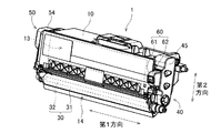
図1は、画像形成装置100の概念図である。この画像形成装置100は、電子写真方式のプリンタである。画像形成装置100の例としては、レーザプリンタやLEDプリンタが挙げられる。画像形成装置100は、4つの現像カートリッジ1と、ドロアユニット91とを備える。ドロアユニット91は、4つの現像カートリッジ1を保持可能なフレームである。画像形成装置100は、4つの現像カートリッジ1から供給される現像剤(例えば、トナー)により、印刷用紙の記録面に画像を形成する。
<1. Configuration of image forming apparatus>
FIG. 1 is a conceptual diagram of the
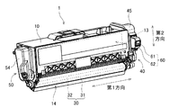
図2は、ドロアユニット91および現像カートリッジ1の斜視図である。図1および図2に示すように、4つの現像カートリッジ1は、ドロアユニット91に対して、個別に交換可能である。現像カートリッジ1の交換時には、画像形成装置100の前面からドロアユニット91が引き出される。そして、ドロアユニット91に設けられた任意のスロット910において、現像カートリッジ1の取り外しおよび取り付けが行われる。4つのスロット910の各々の底部付近には、感光ドラム911が設けられる。
FIG. 2 is a perspective view of the
本実施形態では、1つのドロアユニット91に、4つの現像カートリッジ1が装着される。4つの現像カートリッジ1は、互いに異なる色(例えば、シアン、マゼンタ、イエロー、およびブラックの各色)の現像剤を収容する。ただし、ドロアユニット91に装着される現像カートリッジ1の数は、1〜3つであってもよく、5つ以上であってもよい。
In the present embodiment, four developing
図1に示すように、4つの現像カートリッジ1は、それぞれ、カートリッジIC61を有する。カートリッジIC61は、情報の読み出しおよび書き込みが可能なICチップである。また、画像形成装置100は、制御部92と、ディスプレイ93とを備える。制御部92は、CPU等のプロセッサ921および各種のメモリを有する。制御部92は、例えば、回路基板により構成される。制御部92は、プログラムに従ってプロセッサ921が動作することにより、画像形成装置100における諸処理を実行する。ドロアユニット91に4つの現像カートリッジ1が装着されると、各現像カートリッジ1のカートリッジIC61と、制御部92とが、それぞれ電気的に接続される。ディスプレイ93は、制御部92からの指令に従って、画像形成装置100の動作に関する種々の情報を画面上に表示する。
As shown in FIG. 1, each of the four developing
<2.現像カートリッジの構成>
図3〜図6は、現像カートリッジ1の斜視図である。図3〜図6に示すように、本実施形態の現像カートリッジ1は、ケーシング10、アジテータ20、現像ローラ30、第1ギア部40、第2ギア部50、およびICチップアセンブリ60を有する。
<2. Development Cartridge Configuration>
3 to 6 are perspective views of the developing
ケーシング10は、現像剤を収容可能な筐体である。ケーシング10は、第1端面11と第2端面12との間で第1方向に延びる。第1ギア部40およびICチップアセンブリ60は、第1端面11に位置する。第2ギア部50は、第2端面12に位置する。ケーシング10の内部には、収容室13が設けられる。現像剤は、収容室13内に収容される。ケーシング10は、開口部14を有する。開口部14は、第1方向に対して直交する第2方向におけるケーシング10の端部に位置する。収容室13と外部とは、開口部14を介して連通する。
The
アジテータ20は、アジテータシャフト21と撹拌羽根22とを有する。アジテータシャフト21は、第1方向に沿って延びる。撹拌羽根22は、アジテータシャフト21から径方向外側へ向けて拡がる。アジテータシャフト21の少なくとも一部と、撹拌羽根22とは、収容室13の内部に配置される。アジテータシャフト21の第1方向の両端部には、後述する第1アジテータギア44および第2アジテータギア51が、それぞれ連結される。したがって、アジテータシャフト21および撹拌羽根22は、第1アジテータギア44および第2アジテータギア51と共に回転する。撹拌羽根22が回転すると、収容室13内の現像剤が撹拌される。
The
現像ローラ30は、第1方向に延びる回転軸(第2軸)について回転可能なローラである。現像ローラ30は、ケーシング10の開口部14に配置される。本実施形態の現像ローラ30は、現像ローラ本体31と現像ローラシャフト32とを有する。現像ローラ本体31は、第1方向に延びる円筒状の部材である。現像ローラ本体31の材料には、例えば、弾性を有するゴムが用いられる。現像ローラシャフト32は、現像ローラ本体31を第1方向に貫通する円柱状の部材である。現像ローラシャフト32の材料には、金属または導電性を有する樹脂が用いられる。現像ローラ本体31は、現像ローラシャフト32に対して、相対回転不能に固定される。
The developing
現像ローラシャフト32の第1方向の一方の端部は、後述する現像ローラギア42に対して、相対回転不能に固定される。したがって、現像ローラギア42が回転すると、現像ローラシャフト32も回転し、現像ローラシャフト32と共に現像ローラ本体31も回転する。
One end of the developing
なお、現像ローラシャフト32は、現像ローラ本体31を第1方向に貫通していなくてもよい。例えば、一対の現像ローラシャフト32が、現像ローラ本体31の第1方向の両端から、第1方向にそれぞれ延びていてもよい。
The developing
また、現像カートリッジ1は、図示を省略した供給ローラを有する。供給ローラは、現像ローラ30と収容室13との間に位置する。また、供給ローラは、第1方向に延びる回転軸(第4軸)について回転可能である。現像カートリッジ1が駆動力を受けると、ケーシング10内の収容室13から、供給ローラを介して、現像ローラ30の外周面に、現像剤が供給される。その際、供給ローラと現像ローラ30との間において、現像剤は摩擦帯電される。一方、現像ローラ30の現像ローラシャフト32には、バイアス電圧がかけられている。このため、現像ローラシャフト32と現像剤との間の静電気力によって、現像ローラ本体31の外周面に、現像剤が引き付けられる。
Further, the developing
また、現像カートリッジ1は、図示を省略した層厚規制ブレードを有する。層厚規制ブレードは、現像ローラ本体31の外周面に供給された現像剤を、一定の厚みに成形する。その後、現像ローラ本体31の外周面の現像剤は、ドロアユニット91に設けられた感光ドラム911へ供給される。このとき、現像剤は、感光ドラム911の外周面に形成された静電潜像に応じて、現像ローラ本体31から感光ドラム911へ移動する。これにより、感光ドラム911の外周面において、静電潜像が可視像化される。
Further, the developing
第1ギア部40は、ケーシング10の第1端面11に位置する。図5は、第1ギア部40が分解された状態の現像カートリッジ1の斜視図である。図5に示すように、第1ギア部40は、カップリング41、現像ローラギア42、アイドルギア43、第1アジテータギア44、および第1カバー45を有する。なお、図5では、各ギアの複数のギア歯の図示が省略されている。
The
カップリング41は、画像形成装置100から供給される駆動力を、最初に受けるギアである。カップリング41は、第1方向に延びる回転軸(第3軸)周りに回転することが可能である。カップリング41は、カップリング部411とカップリングギア412とを有する。カップリング部411およびカップリングギア412は、例えば、樹脂により一体に形成される。カップリング部411には、第1方向に凹む締結穴413が設けられている。また、カップリングギア412の外周部には、全周に亘って等間隔に複数のギア歯が設けられている。
The
現像カートリッジ1が装着されたドロアユニット91が、画像形成装置100内に収納されると、画像形成装置100の駆動シャフトが、カップリング部411の締結穴413に挿入される。これにより、駆動シャフトとカップリング部411とが、相対回転不能に連結される。したがって、駆動シャフトが回転すると、カップリング部411が回転し、カップリング部411と共にカップリングギア412も回転する。
When the
現像ローラギア42は、現像ローラ30を回転させるためのギアである。現像ローラギア42は、第1方向に延びる回転軸周りに回転することが可能である。現像ローラギア42の外周部には、全周に亘って等間隔に複数のギア歯が設けられている。カップリングギア412の複数のギア歯の一部と、現像ローラギア42の複数のギア歯の一部とは、互いに噛み合っている。また、現像ローラギア42は、現像ローラ30の現像ローラシャフト32の第1方向の端部に、相対回転不能に装着されている。このため、カップリングギア412が回転すると、現像ローラギア42が回転し、現像ローラギア42と共に現像ローラ30も回転する。
The developing
アイドルギア43は、カップリングギア412の回転を第1アジテータギア44に伝達するためギアである。アイドルギア43は、第1方向に延びる回転軸周りに回転することが可能である。アイドルギア43は、第1方向に配列された大径ギア部431および小径ギア部432を有する。小径ギア部432は、大径ギア部431とケーシング10の第1端面11との間に位置する。言い換えれば、大径ギア部431は、小径ギア部432よりも第1端面11から離れている。小径ギア部432の歯先円の径は、大径ギア部431の歯先円の径よりも小さい。大径ギア部431および小径ギア部432は、例えば、樹脂により一体に形成される。
The
大径ギア部431および小径ギア部432の外周部には、それぞれ、全周に亘って等間隔に複数のギア歯が設けられている。小径ギア部432のギア歯の数は、大径ギア部431のギア歯の数よりも少ない。カップリングギア412の複数のギア歯の一部と、大径ギア部431の複数のギア歯の一部とは、互いに噛み合っている。また、小径ギア部432の複数のギア歯の一部と、第1アジテータギア44の複数のギア歯の一部とは、互いに噛み合っている。カップリングギア412が回転すると、大径ギア部431が回転し、大径ギア部431と共に小径ギア部432も回転する。そして、小径ギア部432の回転に伴い、第1アジテータギア44も回転する。
A plurality of gear teeth are provided on the outer peripheral portions of the large-
第1アジテータギア44は、収容室13内のアジテータ20を回転させるためのギアである。第1アジテータギア44は、第1方向に延びる回転軸周りに回転することが可能である。第1アジテータギア44の外周部には、全周に亘って等間隔に複数のギア歯が設けられている。上述の通り、小径ギア部432の複数のギア歯の一部と、第1アジテータギア44の複数のギア歯の一部とは、互いに噛み合っている。また、第1アジテータギア44は、アジテータシャフト21の第1方向の一方の端部に、相対回転不能に固定されている。このため、カップリング41からアイドルギア43を介して第1アジテータギア44に動力が伝達されると、第1アジテータギア44が回転し、第1アジテータギア44と共にアジテータ20も回転する。
The
第1カバー45は、ケーシング10の第1端面11に、例えばねじ止めで、固定される。カップリングギア412、現像ローラギア42、アイドルギア43、および第1アジテータギア44は、第1端面11と第1カバー45との間に収容される。カップリング部411の締結穴413は、第1カバー45の外部に露出する。本実施形態の第1カバー45は、後述するICチップアセンブリ60のホルダ62を保持するホルダカバーを兼ねている。
The
第2ギア部50は、ケーシング10の第2端面12に位置する。図6は、第2ギア部50が分解された状態の現像カートリッジ1の斜視図である。図6に示すように、第2ギア部50は、第2アジテータギア51、検知ギア52、導電部材53、および第2カバー54を有する。なお、図6では、第2アジテータギア51のギア歯の図示が省略されている。
The
第2アジテータギア51は、アジテータシャフト21の回転を検知ギア52に伝達するためのギアである。第2アジテータギア51は、第1方向に延びる回転軸周りに回転することが可能である。第2アジテータギア51の外周部には、全周に亘って等間隔に複数のギア歯が設けられている。現像カートリッジ1が新品(未使用)の状態では、第2アジテータギア51の複数のギア歯の一部は、検知ギア52の複数のギア歯の一部と、噛み合うことが可能である。また、第2アジテータギア51は、アジテータシャフト21の第1方向の他方の端部に、相対回転不能に固定されている。このため、アジテータシャフト21が回転すると、第2アジテータギア51も回転する。
The
検知ギア52は、画像形成装置100に対して現像カートリッジ1の情報を伝達するためのギアである。現像カートリッジ1の情報には、現像カートリッジ1が新品(未使用)の現像カートリッジであるか、または、使用済みの現像カートリッジであるかの情報が含まれる。また、現像カートリッジ1の情報には、現像カートリッジ1の仕様が含まれる。現像カートリッジ1の仕様には、現像カートリッジ1内の現像剤の量、または、現像剤により印刷可能な印刷枚数を示すイールド情報が含まれる。
The
検知ギア52は、第1方向に延びる回転軸(第1軸)周りに回転することが可能である。検知ギア52は、外周部の一部分に複数のギア歯を有する。新品の現像カートリッジ1をドロアユニット91に装着して、ドロアユニット91を画像形成装置100内に収納すると、カップリング41は、画像形成装置100から駆動力を受ける。そして、カップリング41から、アイドルギア43、第1アジテータギア44、およびアジテータ20を介して伝達される駆動力により、第2アジテータギア51が回転する。検知ギア52は、第2アジテータギア51と噛み合うことによって回転する。ただし、検知ギア52は、外周面の一部分のみにギア歯を有する。このため、検知ギア52が所定の角度回転すると、第2アジテータギア51と検知ギア52との噛み合いが外れ、検知ギア52の回転が停止する。
The
このように、画像形成装置100において一旦使用された現像カートリッジ1では、第2アジテータギア51と検知ギア52との噛み合いが外れている。このため、一旦使用された現像カートリッジ1を、画像形成装置100から取り外して、再度画像形成装置100に装着した場合には、第2アジテータギア51の回転が、検知ギア52へ伝達されない。したがって、検知ギア52は回転しない。
As described above, in the developing
なお、第2アジテータギア51と検知ギア52との間に、他のギアが配置されていてもよい。例えば、第2ギア部50は、第2アジテータギア51および検知ギア52の双方と噛み合う第2アイドルギアを有していてもよい。そして、第2アジテータギア51の回転が、第2アイドルギアを介して、検知ギア52に伝達されてもよい。
Note that another gear may be disposed between the
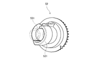
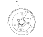
図7は、検知ギア52の斜視図である。図6および図7に示すように、検知ギア52は、第1突起521を有する。第1突起521は、第1方向に突出する。また、第1突起521は、検知ギア52の回転軸を中心として円弧状に延びる。検知ギア52が回転すると、第1突起521も回転する。すなわち、第1突起521の位置は、検知ギア52の回転に伴って変化する。
FIG. 7 is a perspective view of the
導電部材53は、導電性の部材である。導電部材53の材料には、導体である金属または導電性の樹脂が用いられる。導電部材53は、ケーシング10の第2端面12に位置する。導電部材53は、第1方向に突出した円筒状のギアシャフト531を有する。検知ギア52は、ギアシャフト531に支持されつつ、ギアシャフト531の周りを回転する。図7に示すように、第1突起521は、ギアシャフト531の周囲を部分的に覆う。また、導電部材53は、軸受部532を有する。軸受部532は、現像ローラ30の現像ローラシャフト32に接触する。
The
第2カバー54は、ケーシング10の第2端面12に、例えばねじ止めで、固定される。第2アジテータギア51、検知ギア52、および導電部材53は、第2端面12と第2カバー54との間に収容される。また、第2カバー54は、開口541を有する。第1突起521の一部分およびギアシャフト531の一部分は、開口541を介して露出する。後述するレバー912は、開口541を介して、検知ギア52またはギアシャフト531に接触する。
The
<3.検知機構について>
ドロアユニット91は、レバー912と光センサ913とを有する。図8および図9は、第1突起521、ギアシャフト531、レバー912、光センサ913、および制御部92の関係を示した図である。図8および図9に示すように、レバー912は、ギアシャフト531および第1突起521に接触可能である。
<3. About detection mechanism>
The
レバー912の表面には、導電性の金属板914が取り付けられている。金属板914には、制御部92から電力が供給される。図8のように、金属板914がギアシャフト531に接触すると、金属板914と、導電部材53および現像ローラシャフト32とが、電気的に導通する。画像形成装置100の駆動時には、金属板914から供給される電力により、現像ローラシャフト32が所定のバイアス電圧に維持される。
A
ただし、第1突起521は、ギアシャフト531の外周面を部分的に覆う。このため、ドロアユニット91に新品の現像カートリッジ1が挿入された後、検知ギア52が回転しているときには、金属板914とギアシャフト531との接触状態が、検知ギア52の形状に応じて変化する。すなわち、金属板914は、一時的にギアシャフト531から離れて、図9のように、第1突起521のみと接触する。このように、レバー912は、金属板914がギアシャフト531に接触する第1位置と、金属板914がギアシャフト531から離れる第2位置との間で移動する。
However, the
光センサ913は、レバー912の変位を検出し、検出信号を制御部92へ送信する。光センサ913には、例えば、投光部と受光部とを有するセンサユニットが用いられる。レバー912が第1位置にあるときには、投光部からの光は、レバーに遮られることなく、受光部に入射する。一方、レバー912が第2位置にあるときは、投光部からの光が、レバー912に遮られる。したがって、投光部からの光は、受光部に入射しない。このように、光センサ913は、受光部に入射される光の有無によって、レバー912の位置が、第1位置および第2位置のいずれであるかを特定できる。制御部92は、光センサ913から得られる検出信号に基づいて、装着された現像カートリッジ1が新品であるか否か、および現像カートリッジ1の仕様を識別する。
The
このように、本実施形態の光センサ913は、レバー912を介して、第1突起521の移動を検出する。ただし、光センサ913は、第1突起521の移動を直接検出してもよい。また、光センサ913に代えて、磁気センサあるいは接触式センサを用いてもよい。金属板914とギアシャフト531との間の電気的導通の有無に基づいて、第1突起521の移動を検出してもよい。
As described above, the
また、本実施形態では、ギアシャフト531が導電部材53の一部である。しかしながら、導電部材53への給電経路とは別に、ギアシャフトを設けてもよい。例えば、ケーシング10が、第2端面12を貫通する貫通孔と、貫通孔に取り付けられたキャップとをさらに有し、当該キャップから第1方向にギアシャフトが延びてもよい。
In the present embodiment, the
<4.ICチップアセンブリについて>
ICチップアセンブリ60は、ケーシング10の第1端面11の外側に配置される。図3〜図6に示すように、ICチップアセンブリ60は、ICチップであるカートリッジIC61と、ホルダ62とを有する。カートリッジIC61は、ホルダ62の外表面に固定される。ホルダ62は、第1カバー45に保持される。カートリッジIC61は、電気的接触面を有する。電気的接触面は、導体である金属からなる。また、カートリッジIC61は、記憶媒体であるメモリを有する。カートリッジIC61のメモリは、現像カートリッジ1に関する種々の情報を記憶可能である。
<4. About IC Chip Assembly>
The
ドロアユニット91は、スロット910ごとに電気コネクタを有する。電気コネクタは、画像形成装置100内の制御部92と、電気的に接続されている。現像カートリッジ1がドロアユニット91に装着されると、ドロアユニット91の電気コネクタと、カートリッジIC61の電気的接触面とが、互いに接触する。これにより、画像形成装置100は、カートリッジIC61からの情報の読み出しおよびカートリッジIC61への情報の書き込みを行うことが可能となる。
The
図10は、カートリッジIC61のメモリ内の記憶領域を、概念的に示した図である。図10に示すように、本実施形態のカートリッジIC61は、第1記憶領域611、第2記憶領域612、および第3記憶領域613を有する。第1記憶領域611には、第1イールド情報71が記憶されている。第1イールド情報71は、現像カートリッジ1内の現像剤の量、または、現像カートリッジ1内の現像剤により印刷可能な印刷枚数を示す。第2記憶領域612は、不一致情報74を記憶することが可能である。不一致情報74は、後述するステップS1〜S19の処理で、第1イールド情報71と、第1突起521から得られる第2イールド情報72とが一致しなかったことを示す。第3記憶領域613は、残量情報75を記憶することが可能である。残量情報75は、現像カートリッジ1内の現像剤の残量を表す。
FIG. 10 is a diagram conceptually showing the storage area in the memory of the
現像カートリッジ1の出荷時の状態(使用済みの現像カートリッジがリサイクルされて出荷される場合も含む)では、第1記憶領域611に第1イールド情報71が記憶されている。ただし、現像カートリッジ1の出荷時の状態では、第2記憶領域612に不一致情報74は記憶されていない。また、現像カートリッジ1の出荷時の状態では、第3記憶領域613に残量情報75は記憶されていない。
In the state of the developing
<5.本体の制御部について>
図11は、制御部92と4つのカートリッジIC61との接続を、概念的に示したブロック図である。図11に示すように、制御部92は、プロセッサ921、記憶部922、本体IC923、RAM924、およびNVRAM925を有する。プロセッサ921は、CPUなどの演算処理装置である。プロセッサ921は、記憶部922、本体IC923、RAM924、およびNVRAM925のそれぞれに対して、情報の書き込みおよび情報の読み出しを行うことができる。また、プロセッサ921は、4つのカートリッジIC61のそれぞれに対して、情報の書き込みおよび情報の読み出しを行うことができる。記憶部922は、プロセッサ921により読み取り可能なプログラムPを記憶する。制御部92は、プロセッサ921が記憶部922から読み出されたプログラムPを実行することによって、動作する。
<5. About the control unit of the main unit>
FIG. 11 is a block diagram conceptually showing the connection between the
4つのカートリッジIC61には、それぞれ、第1認証情報76が記憶されている。また、本体IC923には、第1認証情報76に対応する第2認証情報77が記憶されている。後述する認証処理では、プロセッサ921が、カートリッジIC61内の第1認証情報76と本体IC923内の第2認証情報77とを用いて、認証の成否を判断する。
RAM924は、情報の書き込みおよび読み出しが可能な揮発性のメモリである。プロセッサ921は、カートリッジIC61に記憶された情報を、RAM924に展開する。これにより、プロセッサ921は、カートリッジIC61に記憶されている情報を、RAM924から迅速に読み出すことができる。また、プロセッサ921は、カートリッジIC61に書き込むべき情報を、一旦RAM924に書き込み、その後、RAM924からカートリッジIC61にコピーする。
The
制御部92は、後述する新品検知によって、第2イールド情報72を取得すると、取得した第2イールド情報72を、RAM924に記憶させる。また、本実施形態では、記憶部922に、予め第3イールド情報73が記憶されている。第3イールド情報73は、後述するステップS7またはステップS19において参照される。第3イールド情報73は、現像カートリッジ1において使用可能な現像剤の量、または、現像剤により印刷可能な印刷枚数を表す。ただし、第3イールド情報73が表す現像剤の量は、第1イールド情報71および第2イールド情報72の各々が表す現像剤の量よりも、少ないことが好ましい。また、第3イールド情報73が表す印刷枚数は、第1イールド情報71および第2イールド情報72の各々が表す印刷枚数よりも、少ないことが好ましい。
When the
NVRAM925は、電源の供給が停止したときにも記憶を保持可能なメモリである。NVRAM925には、現像カートリッジ1に関連する情報が記憶される。画像形成装置100に新品の現像カートリッジ1が装着されると、プロセッサ921は、NVRAM925内の現像カートリッジ1に関連する情報を初期化する。
The
また、本実施形態では、後述する新品検知の開始時に、NVRAM925にフラグ情報が記録される。そして、新品検知の終了時に、NVRAM925からフラグ情報が消去される。新品検知の実行中に、画像形成装置100への電力の供給が停止すると、NVRAM925にフラグ情報が残る。このフラグ情報は、新品検知の実行中に画像形成装置100への電力の供給が停止したことを示す停止情報78として、参照可能となる。
Further, in the present embodiment, flag information is recorded in the
<6.現像カートリッジ装着後の処理>
続いて、現像カートリッジ1の装着後に実行される処理について、図12および図13のフローチャートを参照しつつ、説明する。なお、以下の処理のうち、制御部92が行う処理は、プログラムPに従ってプロセッサ921が動作することによって、実行される。また、以下では、1つの現像カートリッジ1に対する処理を説明するが、同様の処理が、4つの現像カートリッジ1のそれぞれについて実行される。
<6. Processing after developing cartridge is mounted>
Next, processing executed after the developing
ドロアユニット91に現像カートリッジ1が装着され、画像形成装置100にドロアユニット91が収納されると、制御部92は、まず、現像カートリッジ1の有無を確認する(ステップS1)。画像形成装置100は、ドロアユニット91のスロット910ごとに、現像カートリッジ1の有無を検出するカートリッジセンサ(図示省略)を有する。制御部92は、カートリッジセンサから出力される信号に基づいて、スロット910ごとに現像カートリッジ1の有無を判断する。なお、制御部92は、上述した光センサ913から出力される信号を利用して、現像カートリッジ1の有無を判断してもよい。
When the developing
制御部92は、ドロアユニット91のスロット910に、現像カートリッジ1が無いと判断した場合には、ディスプレイ93にエラーまたは警告の表示を行う(ステップS2)。これにより、制御部92は、ドロアユニット91のスロット910に、現像カートリッジ1が装着されていない、または現像カートリッジ1の装着が不完全であることを、ユーザに通知する。
When determining that the developing
一方、制御部92は、ステップS1において、ドロアユニット91のスロット910に、現像カートリッジ1が有ると判断した場合には、次に、カートリッジIC61の認証を行う(ステップS3)。
On the other hand, if the
カートリッジIC61の認証が成功すると、制御部92は、カートリッジIC61から情報を取得する(ステップS4)。具体的には、まず、制御部92は、カートリッジIC61に記憶された情報を、RAM924に書き込む。本実施形態では、制御部92は、第1記憶領域611に記憶された第1イールド情報71を、RAM924にコピーする。第2記憶領域612に不一致情報74が記憶されている場合には、制御部92は、その不一致情報74も、RAM924にコピーする。また、第3記憶領域613に残量情報75が記憶されている場合には、制御部92は、その残量情報75も、RAM924にコピーする。
When the authentication of the
ただし、新品の現像カートリッジ1を画像形成装置100に初めて装着した場合には、カートリッジIC61に、不一致情報74および残量情報75は記憶されていない。したがって、第1イールド情報71、不一致情報74、および残量情報75のうち、第1イールド情報71のみが、RAM924に書き込まれる。一方、現像カートリッジ1の使用を開始した後、画像形成装置100から現像カートリッジ1を一旦取り外して、再度装着した場合は、カートリッジIC61に、不一致情報74および残量情報75も、記憶されている場合がある。この場合には、第1イールド情報71だけではなく、不一致情報74および残量情報75も、RAM924に書き込まれる。
However, when a new developing
次に、制御部92は、RAM924内の情報を確認することによって、第2記憶領域612に不一致情報74が記憶されているかを確認する(ステップS5)。RAM924内に不一致情報74が記憶されていれば、制御部92は、第2記憶領域612に不一致情報74が記憶されていると判断する。不一致情報74は、その現像カートリッジ1について、後述の新品検知が既に1回以上実行済みであり、かつ、カートリッジIC61に記憶された第1イールド情報71と、検知ギア52から得られる第2イールド情報72とが、一致しなかったことを示す。これは、通常とは異なる特殊な状況である。
Next, the
RAM924に不一致情報74がある場合、制御部92は、予め準備されたメッセージを、ディスプレイ93に表示する(ステップS6)。これにより、通常とは異なる特殊な状況であることを、ユーザに通知する。
When there is the
ステップS6の後、制御部92は、RAM924に記憶された第1イールド情報71および第2イールド情報72を確認する。そして、制御部92は、第1イールド情報72が表す現像剤の量または印刷枚数と、第2イールド情報72が表す現像剤の量または印刷枚数とのうち、小さい方の値に基づいて、印刷処理を実行する。あるいは、制御部92は、記憶部922に記憶された第3イールド情報73が表す現像剤の量または印刷枚数に基づいて、印刷処理を実行する。これにより、制御部92は、例えば印刷のかすれ等が確実に生じない安全な範囲で、印刷処理を行う(ステップS7)。
After step S6, the
一方、ステップS5において、RAM924に不一致情報74が無い場合には、次に、制御部92は、NVRAM925に停止情報78が記憶されているかを確認する(ステップS8)。停止情報78は、NVRAM925内の、上述した未消去のフラグ情報である。停止情報78は、その現像カートリッジ1について、後述の新品検知が既に1回以上実行済みであり、かつ、新品検知の実行中に、画像形成装置100への電力の供給が停止されたことを示す。この場合、新品検知によって取得された第2イールド情報72の信頼性は低いと推測される。
On the other hand, if there is no
したがって、NVRAM925に停止情報78がある場合には、制御部92は、RAM924に記憶された第1イールド情報71が表す現像剤の量または印刷枚数に基づいて、印刷処理を実行する(ステップS9)。
Therefore, when there is the
一方、NVRAM925に停止情報78が記憶されていない場合には、次に、制御部92は、4つの現像カートリッジ1のそれぞれについて、新品検知を行う。具体的には、制御部92は、まず、モータの駆動を開始させて駆動シャフトを回転させる(ステップS10)。そうすると、駆動シャフトの回転が、カップリング41、アイドルギア43、第1アジテータギア44、アジテータ20、および第2アジテータギア51を介して、検知ギア52に伝達する。これにより、検知ギア52が回転を開始する。検知ギア52が回転すると、検知ギア52と共に第1突起521も回転する。そして、第1突起521の移動に応じて、レバー912の傾きが変化する。光センサ913は、レバー912の変位に応じて変化する検出信号を、制御部92へ送信する。これにより、制御部92は、検知ギア52の回転に応じて変化する入力波形を取得する(ステップS11)。
On the other hand, when the
やがて、第2アジテータギア51と検知ギア52との噛み合いが外れると、検知ギア52は回転を停止する。また、モータの駆動を開始した後、予め設定された時間が経過すると、制御部92は、モータの駆動を停止させる(ステップS12)。
Eventually, when the engagement between the
続いて、制御部92は、取得した入力波形が、現像カートリッジ1が新品であることを示す新品波形であるかを判断する(ステップS13)。入力波形が新品波形でない場合は、一旦使用が開始された現像カートリッジ1が画像形成装置100から取り出され、再度画像形成装置100に装着されたと考えられる。この場合、制御部92は、RAM924に記憶された第1イールド情報71が表す現像剤の量または印刷枚数に基づいて、印刷処理を実行する(ステップS14)。
Subsequently, the
一方、入力波形が新品波形である場合は、次に、制御部92は、RAM924に記憶された第1イールド情報71と、入力波形に基づいて決定される第2イールド情報72とが、一致するかを判定する(ステップS15)。そして、第1イールド情報71と第2イールド情報72とが一致すれば、制御部92は、正常な状態であると判断する。この場合、制御部92は、第1イールド情報71が表す現像剤の量または印刷枚数と、第2イールド情報72が表す現像剤の量または印刷枚数とのいずれか一方に基づいて、印刷処理を実行する(ステップS16)。
On the other hand, when the input waveform is a new waveform, the
一方、ステップS15において、RAM924に記憶された第1イールド情報71と、入力波形に基づいて決定される第2イールド情報72とが、一致しない場合は、通常とは異なる特殊な状況と考えられる。この場合、制御部92は、予め準備されたメッセージを、ディスプレイ93に表示する(ステップS17)。これにより、通常とは異なる特殊な状況であることを、ユーザに通知する。
On the other hand, when the
ステップS17の後、制御部92は、カートリッジIC61に不一致情報74を書き込む(ステップS18)。具体的には、まず、プロセッサ921が、RAM924に不一致情報74を書き込む。そして、RAM924内の不一致情報74が、その都度または定期的に、カートリッジIC61に書き込まれる。具体的には、不一致情報74が、カートリッジIC61の第2記憶領域612に書き込まれる。
After step S17, the
なお、本実施形態では、制御部92は、第1イールド情報71と第2イールド情報72とが一致しない場合にのみ、カートリッジIC61に不一致情報74を書き込む。しかしながら、制御部92は、第1イールド情報71と第2イールド情報72とが一致した場合には、カートリッジIC61に一致情報を書き込んでもよい。すなわち、ステップS18では、制御部92が、第1イールド情報71と第2イールド情報72との間に不整合が生じたかの確認結果を示すイールド確認情報を、カートリッジIC61の第2記憶領域612に書き込めばよい。
In the present embodiment, the
ステップS18の後、制御部92は、RAM924に記憶された第1イールド情報71および第2イールド情報72を確認する。そして、制御部92は、第1イールド情報71が表す現像剤の量または印刷枚数と、第2イールド情報72が表す現像剤の量または印刷枚数とのうち、小さい方の値に基づいて、印刷処理を実行する。あるいは、制御部92は、記憶部922に記憶された第3イールド情報73が表す現像剤の量または印刷枚数に基づいて、印刷処理を実行する。これにより、制御部92は、例えば、印刷のかすれ等が確実に生じない安全な範囲で、印刷処理を行う(ステップS19)。
After step S18, the
このように、この現像カートリッジ1では、カートリッジIC61に記憶された第1イールド情報71と、検知ギア52の第1突起521から得られる第2イールド情報72とに基づいて、現像カートリッジ1内の現像剤の量、または、現像剤により印刷可能な印刷枚数を確認可能である。これにより、制御部92は、印刷処理の実行時に参照すべき現像剤の量または印刷枚数を決定できる。画像形成装置100は、決定された現像剤の量または印刷枚数に基づいて、印刷処理を実行する。
As described above, in the developing
このため、通常とは異なる特殊な状況においても、印刷のかすれ等が生じない範囲で、印刷処理を行うことができる。 For this reason, even in a special situation that is different from usual, it is possible to perform the printing process within a range in which printing fading does not occur.
<7.残量更新処理について>
続いて、カートリッジIC61の第3記憶領域613に記憶される現像剤の残量情報75を更新する処理について、図14のフローチャートを参照しつつ説明する。制御部92は、上述したステップS1〜S19の処理が完了した後、残量情報75の更新処理を、予め定められたタイミングで、繰り返し実行する。
<7. About remaining amount update processing>
Next, processing for updating the developer remaining
残量情報75の更新処理を実行するときには、まず、制御部92が、現像剤の使用量を確認する(ステップS31)。制御部92は、現像剤の使用量をRAM924に記憶し、印刷処理を実行する度に更新する。また、RAM924には、上述したステップS7,S9,S14,S16,またはS19において決定された現像剤の量が記憶されている。
When executing the update process of the remaining
制御部92は、RAM924に記憶された現像剤の量と現像剤の使用量とを比較する(ステップS32)。これにより、制御部92は、現像カートリッジ1内の現像剤の残量を示す残量情報75を決定する。制御部92は、例えば、RAM924に記憶された現像剤の量から、現像剤の使用量を差し引くことによって、残量情報75を算出する。
The
制御部92は、残量情報75を決定すると、次に、残量情報75が示す現像剤の残量が、印刷処理を継続するために十分な量であるかを判断する(ステップS33)。具体的には、制御部92は、残量情報73が示す現像剤の残量が、NVRAM925に記憶された閾値以下であるかを判断する。そして、現像剤の残量が閾値以下でない場合には、制御部92は、現像剤の残量が十分にあると判断する。その場合、制御部92は、カートリッジIC61に残量情報75を書き込んで(ステップS34)、次の印刷指示の入力を待つ。ステップS34では、具体的には、まず、プロセッサ921が、RAM924に残量情報75を書き込む。そして、制御部92は、RAM924内の残量情報75を、その都度または定期的に、カートリッジIC61の第3記憶領域613に書き込む。
After determining the remaining
一方、ステップS33において、現像剤の残量が閾値以下である場合には、制御部92は、現像剤の残量が十分でないと判断する。その場合、制御部92は、ディスプレイ93にエラーまたは警告の表示を行った後(ステップS35)、カートリッジIC61に残量情報75を書き込む(ステップS34)。
On the other hand, when the remaining amount of developer is equal to or less than the threshold value in step S33, the
<8.変形例>
以上、本発明の一実施形態について説明したが、本発明は上記の実施形態に限定されるものではない。以下では、種々の変形例について、上記の実施形態との相違点を中心に説明する。
<8. Modification>
Although one embodiment of the present invention has been described above, the present invention is not limited to the above embodiment. Hereinafter, various modifications will be described focusing on differences from the above-described embodiment.
<8−1.第1変形例>
図15は、第1変形例の第1突起521、ギアシャフト531、レバー912、光センサ913、および制御部92の関係を示した図である。図15の例では、検知ギア52の回転軸を中心とする第1突起521の周方向の長さが、上記の実施形態よりも短い。したがって、検知ギア52の回転に伴って、レバー912がギアシャフト531から離れる時間が、上記の実施形態よりも短い。このように、第1突起521は、円弧状に延びていなくてもよい。
<8-1. First Modification>
FIG. 15 is a diagram illustrating a relationship among the
<8−2.第2変形例>
図16は、第2変形例の第1突起521、第2突起522、ギアシャフト531、レバー912、光センサ913、および制御部92の関係を示した図である。図16の例では、検知ギア52が、第1突起521と第2突起522とを有する。第1突起521および第2突起522は、検知ギア52の回転軸の周囲の異なる位置において、それぞれ第1方向に延びる。検知ギア52の回転軸に対する第1突起521の外端部(第1外端部)と、検知ギア52の回転軸に対する第2突起522の外端部(第2外端部)とは、周方向に離れている。
<8-2. Second Modification>
FIG. 16 is a diagram illustrating a relationship among the
画像形成装置100に現像カートリッジ1が装着されて、検知ギア52が回転すると、検知ギア52と共に第1突起521および第2突起522の位置が移動する。これにより、第1突起521がレバー912に接触する。そして、第1突起521のレバー912への接触よりも後または前に、第2突起522がレバー912に接触する。したがって、検知ギア52の回転に伴って、レバー912が、第1位置から第2位置へ2回動く。光センサ913は、レバー912が2回動くことを検出する。
When the developing
このように、検知ギア52に2つの突起を設ければ、2つの突起の周方向の間隔や、各突起の周方向の長さによって、光センサの検出信号が変化する。したがって、2つの突起の位置や形状によって、多数の異なる第2イールド情報を表すことができる。
Thus, if two protrusions are provided on the
<8−3.第3変形例>
図17は、第3変形例の第1突起521、第2突起522、第3突起523、ギアシャフト531、レバー912、光センサ913、および制御部92の関係を示した図である。図17の例では、検知ギア52が、第1突起521、第2突起522、および第3突起523を有する。第1突起521、第2突起522、および第3突起523は、検知ギア52の回転軸の周囲の異なる位置に配置される。検知ギア52が回転すると、検知ギア52と共に第1突起521、第2突起522、および第3突起523の位置が移動する。したがって、検知ギア52の回転に伴って、レバー912が、第1位置から第2位置へ3回動く。光センサ913は、レバー912が3回動くことを検出する。
<8-3. Third Modification>
FIG. 17 is a diagram illustrating a relationship among the
このように、検知ギア52に3つの突起を設ければ、3つの突起の周方向の間隔や、各突起の周方向の長さによって、光センサの検出信号が変化する。したがって、3つの突起の位置や形状によって、多数の異なるイールド情報を表すことができる。
As described above, if the
なお、検知ギア52が有する突起の数は、4つ以上であってもよい。
Note that the number of protrusions included in the
<8−4.第4変形例>
図18は、第4変形例の第1突起521、第2突起522、ギアシャフト531、レバー912、光センサ913、および制御部92の関係を示した図である。図18の例では、検知ギア52が、第1突起521と第2突起522とを有する。第1突起521および第2突起522は、検知ギア52の回転軸の周囲の異なる位置において、それぞれ第1方向に延びる。検知ギア52の回転軸に対する第1突起521の外端部(第1外端部)と、検知ギア52の回転軸に対する第2突起522の外端部(第2外端部)とは、周方向に離れている。
<8-4. Fourth Modification>
FIG. 18 is a diagram illustrating a relationship among the
画像形成装置100に現像カートリッジ1が装着されて、検知ギア52が回転すると、検知ギア52と共に第1突起521および第2突起522の位置が移動する。これにより、第1突起521がレバー912に接触する。そして、第1突起521のレバー912への接触よりも後または前に、第2突起522がレバー912に接触する。したがって、検知ギア52の回転に伴って、レバー912が、第1位置から第2位置へ2回動く。光センサ913は、レバー912が2回動くことを検出する。
When the developing
また、図18の例では、第1突起521の周方向の長さよりも、第2突起522の周方向の長さの方が長い。このため、第1突起521によりレバー912が第2位置に位置する時間よりも、第2突起522によりレバー912が第2位置に位置する時間の方が長くなる。このように、第1突起521と第2突起522との周方向の長さを、互いに相違させれば、光センサ913は、第1突起521によりレバー912が第2位置に位置する時間と、第2突起522によりレバー912が第2位置に位置する時間とを、それぞれ異なる時間として検出できる。このため、第1突起521と第2突起522とで、より多くの第2イールド情報を表すことができる。
In the example of FIG. 18, the circumferential length of the
<8−5.第5変形例>
図19は、第5変形例の検知ギア52、光センサ913、および制御部92の関係を示した図である。図19の例では、検知ギア52と、第1突起521とが、互いに別部材となっている。検知ギア52は、複数のギア歯を有し、回転軸を中心として回転する。検知ギア52が回転すると、検知ギア52の表面形状に沿って、第1突起521が軸方向に移動する。光センサ913は、第1突起521の軸方向の変位に応じて変化する検出信号を、制御部92へ送信する。制御部92は、光センサ913から得られる検出信号に基づいて、装着された現像カートリッジ1に関する第2イールド情報72を取得する。
<8-5. Fifth Modification>
FIG. 19 is a diagram illustrating a relationship among the
このように、検知ギア52と第1突起521とは、別部材であってもよい。また、第1突起521は、軸方向に変位するものであってもよい。
Thus, the
<8−6.第6変形例>
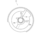
図20は、第6変形例の現像カートリッジ1の斜視図である。この現像カートリッジ1は、ケーシング10の第1方向の一方の端面である第1端面11のみに、ギア部40を有する。ギア部40は、カバー45に覆われている。図21は、カバー45を取り外した状態で、ギア部40を第1方向に見た平面図である。図21のように、この例では、カップリング41から検知ギア52までの複数のギアが、ケーシング10の第1端面11に配置されている。このように、ケーシング10の第1端面11に、複数のギアを集約して配置してもよい。なお、カートリッジICは、例えば、ケーシング10の第1方向の他方の端面である第2端面に配置すればよい。
<8-6. Sixth Modification>
FIG. 20 is a perspective view of the developing
図22は、第6変形例の検知ギア52の平面図である。図22の検知ギア52は、円筒部520、第1突起521、および第2突起522を有する。円筒部520は、検知ギア52の第1方向の一方の端面から、第1方向に延びる。第1突起521および第2突起522は、それぞれ、円筒部520から径方向外側へ向けて延びる。第1突起521と第2突起522とは、周方向の異なる位置に配置される。また、図22の例では、第2突起522の周方向の長さが、第1突起521の周方向の長さよりも長い。このように、第1突起521および第2突起522は、径方向に延びる突起であってもよい。
FIG. 22 is a plan view of the
<8−7.第7変形例>
図23は、第7変形例の検知ギア52の平面図である。図23の例では、第1突起521の周方向の長さと、第2突起522の周方向の長さとが、同一である。すなわち、図23の例では、図22の例よりも、第2突起522の周方向の長さが短い。図22および図23のように、第2突起522の周方向の長さを変えることによって、異なる第2イールド情報を表すことができる。
<8-7. Seventh Modification>
FIG. 23 is a plan view of the
<8−8.第8変形例>
図24は、第8変形例の検知ギア52の平面図である。図24の例では、第1突起521の周方向の長さと、第2突起522の周方向の長さとが、同一である。すなわち、図24の例では、図22の例よりも、第2突起522の周方向の長さが短い。図22および図24のように、第2突起522の周方向の長さを変えることによって、異なる第2イールド情報を表すことができる。
<8-8. Eighth Modification>
FIG. 24 is a plan view of the
また、図24の例では、図22の例よりも、第1突起521と第2突起522との間の周方向の間隔が大きい。図23および図24のように、第1突起521と第2突起522との間の周方向の間隔を変えることによって、異なる第2イールド情報を表すことができる。
In the example of FIG. 24, the circumferential interval between the
<8−9.第9変形例>
図25は、第9変形例の検知ギア52の平面図である。図25の例では、検知ギア52が、第1突起521、第2突起522、および第3突起523を有する。第1突起521、第2突起522、および第3突起523は、それぞれ、円筒部520から径方向外側へ向けて延びる。また、第1突起521、第2突起522、および第3突起523は、周方向の異なる位置に配置される。このように、検知ギア52に3つの突起を設ければ、3つの突起の周方向の間隔や、各突起の周方向の長さによって、光センサの検出信号が変化する。したがって、3つの突起の位置や形状によって、より多くの異なる第2イールド情報を表すことができる。
<8-9. Ninth Modification>
FIG. 25 is a plan view of the
なお、検知ギア52が有する突起の数は、4つ以上であってもよい。
Note that the number of protrusions included in the
<8−10.他の変形例>
上記の実施形態では、ホルダの外表面に、電気的接触面を有するカートリッジICが固定されていた。しかしながら、ホルダの外表面には、電気的接触面のみを固定し、カートリッジICのメモリは、現像カートリッジの他の箇所に配置されていてもよい。
<8-10. Other variations>
In the above embodiment, the cartridge IC having an electrical contact surface is fixed to the outer surface of the holder. However, only the electrical contact surface may be fixed to the outer surface of the holder, and the memory of the cartridge IC may be arranged at other portions of the developing cartridge.
また、上記の実施形態では、第1ギア部および第2ギア部内の複数のギアが、互いに、ギア歯の噛み合いによって係合していた。しかしながら、第1ギア部および第2ギア部内の複数のギアは、摩擦力により互いに係合していてもよい。例えば、互いに係合する2つのギアの外周部に、複数のギア歯の代わりに、摩擦部材(例えばゴム)が設けられてもよい。 In the above embodiment, the plurality of gears in the first gear portion and the second gear portion are engaged with each other by meshing gear teeth. However, the plurality of gears in the first gear portion and the second gear portion may be engaged with each other by frictional force. For example, instead of a plurality of gear teeth, a friction member (for example, rubber) may be provided on the outer periphery of two gears that engage with each other.
また、上記の実施形態では、画像形成装置のディスプレイに情報を表示することによって、エラーメッセージ等の通知を出力していた。しかしながら、ディスプレイへの情報の表示に代えて、または、ディスプレイへの情報の表示と共に、ブザー、音声、警告灯、印字出力等の他の方法で、通知を出力してもよい。 In the above-described embodiment, notification of an error message or the like is output by displaying information on the display of the image forming apparatus. However, instead of displaying information on the display, or together with displaying information on the display, the notification may be output by other methods such as a buzzer, sound, warning light, and print output.
また、上記の実施形態は、ドロアユニット91に装着可能な現像カートリッジ1を用いて説明されていた。しかしながら、現像カートリッジ1は、ドラムカートリッジに装着可能であってもよい。ドラムカートリッジは、1つの感光ドラムを有するカートリッジである。また、現像カートリッジ1は、感光ドラムを有するプロセスカートリッジであってもよい。プロセスカートリッジは、現像ローラと感光ドラムとを備える1つのカートリッジである。また、現像カートリッジ1の代わりに、トナーカートリッジが用いられてもよい。トナーカートリッジは、トナーを収容可能であり、かつ、現像ローラ1を有さないカートリッジである。
Further, the above embodiment has been described using the developing
また、上記実施形態では、光センサ913が、レバー912の変位を検出した。しかしながら、光センサ913の代わりに、電気的な接続を検出する検出機構が用いられてもよい。この場合、第1突起521と第2突起522と第3突起523のいずれかの突起が、レバー912と接触し、レバー912が第2位置に配置されると、画像形成装置内のある電気回路の電気的な接続がONとなる。そして、電気回路の電気的な接続がONとなったことを、検出機構が検出する。一方、第1突起521と第2突起522と第3突起523のいずれの突起も、レバー912と接触しない場合、レバー912は第1位置に配置され、電気回路の電気的な接続がOFFとなる。そして、電気回路の電気的な接続がOFFとなったことを、検出機構が検出する。
In the above embodiment, the
また、現像カートリッジの細部の形状については、本願の各図に示された形状と相違していてもよい。また、上記の実施形態や変形例に登場した各要素を、矛盾が生じない範囲で、適宜に組み合わせてもよい。 Further, the detailed shape of the developing cartridge may be different from the shape shown in each drawing of the present application. Moreover, you may combine suitably each element which appeared in said embodiment and modification in the range which does not produce inconsistency.
1 現像カートリッジ
10 ケーシング
20 アジテータ
30 現像ローラ
40 第1ギア部
41 カップリング
42 現像ローラギア
43 アイドルギア
44 第1アジテータギア
45 第1カバー
50 第2ギア部
51 第2アジテータギア
52 検知ギア
53 導電部材
54 第2カバー
60 ICチップアセンブリ
61 カートリッジIC
62 ホルダ
71 第1イールド情報
72 第2イールド情報
73 第3イールド情報
74 不一致情報
75 残量情報
76 第1認証情報
77 第2認証情報
78 停止情報
91 ドロアユニット
92 制御部
93 ディスプレイ
100 画像形成装置
521 第1突起
522 第2突起
523 第3突起
531 ギアシャフト
611 第1記憶領域
612 第2記憶領域
613 第3記憶領域
910 スロット
911 感光ドラム
912 レバー
913 光センサ
921 プロセッサ
922 記憶部
924 RAM
925 NVRAM
923 本体IC
P プログラム
DESCRIPTION OF
62
925 NVRAM
923 IC
P program
Claims (25)
所定の方向に延びる第1軸に対して回転可能な検知ギアと、
前記検知ギアの回転に伴って位置が移動する第1突起と、
前記カートリッジ内の前記現像剤の量、または、前記現像剤により印刷可能な印刷枚数を示す第1イールド情報を記憶する第1記憶領域を備えるメモリと、
を備え、
前記第1突起と前記第1イールド情報とに基づいて、前記カートリッジ内の前記現像剤の量、または、前記現像剤により印刷可能な印刷枚数を確認可能であることを特徴とするカートリッジ。 A cartridge capable of containing a developer,
A detection gear rotatable with respect to a first axis extending in a predetermined direction;
A first protrusion whose position moves with the rotation of the detection gear;
A memory comprising a first storage area for storing first yield information indicating the amount of the developer in the cartridge or the number of printable sheets by the developer;
With
The cartridge, wherein the amount of the developer in the cartridge or the number of printable sheets by the developer can be confirmed based on the first protrusion and the first yield information.
前記第1突起は、前記所定の方向に延びることを特徴とするカートリッジ。 The cartridge according to claim 1,
The cartridge according to claim 1, wherein the first protrusion extends in the predetermined direction.
前記検知ギアは、前記第1突起を備えることを特徴とするカートリッジ。 The cartridge according to claim 1 or 2, wherein
The cartridge, wherein the detection gear includes the first protrusion.
前記検知ギアの回転に伴って位置が移動する第2突起をさらに備え、
前記第1突起、前記第2突起、および前記第1イールド情報に基づいて、前記カートリッジ内の前記現像剤の量、または、前記現像剤により印刷可能な印刷枚数を確認可能であることを特徴とするカートリッジ。 The cartridge according to any one of claims 1 to 3, wherein
A second protrusion whose position moves with the rotation of the detection gear;
Based on the first protrusion, the second protrusion, and the first yield information, the amount of the developer in the cartridge or the number of prints that can be printed by the developer can be confirmed. Cartridge to be used.
前記第2突起は、前記所定の方向に延びることを特徴とするカートリッジ。 The cartridge according to claim 4, wherein
The cartridge, wherein the second protrusion extends in the predetermined direction.
前記検知ギアは、前記第2突起を備えることを特徴とするカートリッジ。 The cartridge according to claim 4 or 5, wherein
The cartridge, wherein the detection gear includes the second protrusion.
前記第1突起は、前記第1軸に関する径方向の外端に位置する第1外端部を有し、
前記第2突起は、前記第1軸に関する径方向の外端に位置する第2外端部を有し、
前記第1外端部と前記第2外端部とが、前記第1軸に関する周方向において、互いに離れていることを特徴とするカートリッジ。 The cartridge according to any one of claims 4 to 6,
The first protrusion has a first outer end located at a radially outer end with respect to the first axis,
The second protrusion has a second outer end located at a radially outer end with respect to the first axis,
The cartridge, wherein the first outer end portion and the second outer end portion are separated from each other in a circumferential direction with respect to the first axis.
前記第1突起は、前記第1軸に関する周方向に沿って延び、
前記第2突起は、前記第1軸に関する周方向に沿って延び、
前記第1突起の前記周方向の長さと、前記第2突起の前記周方向の長さとが異なり、
前記第1突起の前記周方向の長さ、前記第2突起の前記周方向の長さ、および前記第1イールド情報に基づいて、前記カートリッジ内の前記現像剤の量、または、前記現像剤により印刷可能な印刷枚数を確認可能であることを特徴とするカートリッジ。 The cartridge according to any one of claims 4 to 7,
The first protrusion extends along a circumferential direction with respect to the first axis,
The second protrusion extends along a circumferential direction with respect to the first axis,
The circumferential length of the first protrusion is different from the circumferential length of the second protrusion,
Based on the circumferential length of the first protrusion, the circumferential length of the second protrusion, and the first yield information, the amount of the developer in the cartridge or the developer A cartridge characterized in that the number of printable prints can be confirmed.
画像形成装置に前記カートリッジが装着されて、前記検知ギアが回転することによって、前記第1突起が、前記画像形成装置の一部分に接触可能であることを特徴とするカートリッジ。 The cartridge according to any one of claims 1 to 8, wherein
The cartridge, wherein the cartridge is mounted on the image forming apparatus and the detection gear rotates, whereby the first protrusion can contact a part of the image forming apparatus.
画像形成装置に前記カートリッジが装着されて、前記検知ギアが回転することによって、前記第1突起が、前記画像形成装置の一部分に接触可能であり、
前記第1突起の前記画像形成装置の前記一部分への接触よりも後または前に、前記検知ギアが回転することによって、前記第2突起が、前記画像形成装置の前記一部分に接触可能であることを特徴とするカートリッジ。 The cartridge according to any one of claims 4 to 8,
When the cartridge is mounted on the image forming apparatus and the detection gear rotates, the first protrusion can contact a part of the image forming apparatus;
The second protrusion can contact the part of the image forming apparatus by rotating the detection gear before or after the first protrusion contacts the part of the image forming apparatus. A cartridge characterized by.
前記メモリは、前記第1イールド情報と、前記第1突起から得られる第2イールド情報との間に不整合が生じたかの確認結果を示すイールド確認情報を記憶する第2記憶領域をさらに備えることを特徴とするカートリッジ。 The cartridge according to any one of claims 1 to 10, wherein
The memory further includes a second storage area for storing yield confirmation information indicating a confirmation result of whether or not a mismatch has occurred between the first yield information and the second yield information obtained from the first protrusion. Features cartridge.
駆動力を受けるカップリングをさらに有し、
前記検知ギアは、前記駆動力によって回転可能であることを特徴とするカートリッジ。 The cartridge according to any one of claims 1 to 11,
A coupling that receives driving force;
The cartridge, wherein the detection gear is rotatable by the driving force.
前記所定の方向に延びる第2軸について回転可能な現像ローラであって、前記所定の方向に延びる現像ローラシャフトを備える現像ローラと、
前記現像ローラと共に回転可能な現像ローラギアであって、前記現像ローラシャフトに装着された現像ローラギアと、
をさらに備え、
前記カップリングは、前記所定の方向に延びる第3軸について回転可能であり、
前記カップリングは、さらに、前記カップリングと共に回転可能なカップリングギアであって、前記現像ローラギアと噛み合うカップリングギアを備えることを特徴とするカートリッジ。 The cartridge according to claim 12, wherein
A developing roller rotatable about a second axis extending in the predetermined direction, the developing roller comprising a developing roller shaft extending in the predetermined direction;
A developing roller gear rotatable with the developing roller, the developing roller gear mounted on the developing roller shaft;
Further comprising
The coupling is rotatable about a third axis extending in the predetermined direction;
The cartridge further comprises a coupling gear that is rotatable together with the coupling and that meshes with the developing roller gear.
前記所定の方向に延びる第4軸について回転可能な供給ローラであって、前記現像剤を前記現像ローラへ供給可能な供給ローラをさらに備えることを特徴とするカートリッジ。 14. The cartridge according to claim 13, wherein
A cartridge, further comprising a supply roller that is rotatable about a fourth axis extending in the predetermined direction and capable of supplying the developer to the development roller.
前記メモリを有するICチップを備えることを特徴とするカートリッジ。 The cartridge according to any one of claims 1 to 14,
A cartridge comprising an IC chip having the memory.
所定の方向に延びる第1軸に対して回転可能な検知ギアと、
前記検知ギアの回転に伴って位置が移動する第1突起と、
前記カートリッジ内の前記現像剤の量、または、前記現像剤により印刷可能な印刷枚数を示す第1イールド情報を記憶する第1記憶領域を有するメモリと、
を備えるカートリッジと、
前記カートリッジを保持可能なフレームと、
前記第1突起の移動を検出するセンサと、
前記メモリから読み出される第1イールド情報と、前記センサの検出信号に基づいて得られる第2イールド情報とに基づいて、前記カートリッジ内の前記現像剤の量、または、前記現像剤により印刷可能な印刷枚数を確認する処理を実行可能な制御部と、
を備えることを特徴とする画像形成装置。 A cartridge capable of containing a developer,
A detection gear rotatable with respect to a first axis extending in a predetermined direction;
A first protrusion whose position moves with the rotation of the detection gear;
A memory having a first storage area for storing first yield information indicating the amount of the developer in the cartridge or the number of printable sheets by the developer;
A cartridge comprising:
A frame capable of holding the cartridge;
A sensor for detecting movement of the first protrusion;
Based on the first yield information read from the memory and the second yield information obtained based on the detection signal of the sensor, the amount of the developer in the cartridge or the print that can be printed by the developer A control unit capable of executing processing for checking the number of sheets;
An image forming apparatus comprising:
前記制御部は、前記第1イールド情報と、前記第2イールド情報とが一致するかを判定し、前記判定の結果に基づいて、前記カートリッジ内の前記現像剤の量、または、前記現像剤により印刷可能な印刷枚数を確認することを特徴とする画像形成装置。 The image forming apparatus according to claim 16, wherein
The control unit determines whether the first yield information and the second yield information match, and based on the determination result, the amount of the developer in the cartridge or the developer An image forming apparatus that checks the number of printable sheets.
前記制御部は、前記第1イールド情報と前記第2イールド情報とが一致する場合に、前記第1イールド情報または前記第2イールド情報が表す前記現像剤の量または印刷枚数に基づいて、印刷処理を実行することを特徴とする画像形成装置。 The image forming apparatus according to claim 17,
When the first yield information and the second yield information match, the control unit performs a printing process based on the amount of developer or the number of printed sheets represented by the first yield information or the second yield information. An image forming apparatus characterized in that
前記制御部は、前記第1イールド情報と前記第2イールド情報とが一致しない場合に、前記第1イールド情報が表す前記現像剤の量または印刷枚数と、前記第2イールド情報が表す前記現像剤の量または印刷枚数とのうち、小さい方の値に基づいて、印刷処理を実行することを特徴とする画像形成装置。 The image forming apparatus according to claim 17 or 18, wherein:
When the first yield information and the second yield information do not match, the control unit determines the amount of developer or the number of prints indicated by the first yield information and the developer indicated by the second yield information. An image forming apparatus that executes a printing process based on a smaller value of the amount or the number of printed sheets.
第3イールド情報を記憶する記憶部
をさらに備え、
前記制御部は、前記第1イールド情報と前記第2イールド情報とが一致しない場合に、前記第3イールド情報が表す前記現像剤の量または印刷枚数に基づいて、印刷処理を実行することを特徴とする画像形成装置。 The image forming apparatus according to claim 17 or 18, wherein:
A storage unit for storing third yield information;
When the first yield information and the second yield information do not match, the control unit executes a printing process based on the amount of developer or the number of printed sheets represented by the third yield information. An image forming apparatus.
前記メモリは、第2記憶領域をさらに有し、
前記制御部は、前記第1イールド情報と前記第2イールド情報との間に不整合が生じたかの確認結果を示すイールド確認情報を、前記第2記憶領域に書き込むことを特徴とする画像形成装置。 The image forming apparatus according to any one of claims 17 to 20, wherein
The memory further includes a second storage area,
The image forming apparatus, wherein the control unit writes yield confirmation information indicating a confirmation result of whether or not a mismatch has occurred between the first yield information and the second yield information in the second storage area.
前記制御部は、前記第1イールド情報と、前記第2イールド情報とが一致しない場合に、通知を出力することを特徴とする画像形成装置。 The image forming apparatus according to any one of Claims 17 to 21,
The image forming apparatus according to claim 1, wherein the control unit outputs a notification when the first yield information and the second yield information do not match.
ディスプレイをさらに有し、
前記通知は、前記ディスプレイへの情報の表示であることを特徴とする画像形成装置。 The image forming apparatus according to claim 22, wherein
Further having a display,
The image forming apparatus according to claim 1, wherein the notification is a display of information on the display.
前記センサによる検出処理の実行中に、前記画像形成装置への電力の供給が停止されたことを示す停止情報を記憶する不揮発性メモリをさらに有し、
前記制御部は、
前記不揮発性メモリに前記停止情報が記憶されている場合に、前記第1イールド情報が表す前記現像剤の量または印刷枚数に基づいて、印刷処理を実行することを特徴とする画像形成装置。 The image forming apparatus according to any one of Claims 17 to 21,
A non-volatile memory that stores stop information indicating that power supply to the image forming apparatus is stopped during detection processing by the sensor;
The controller is
An image forming apparatus, wherein when the stop information is stored in the non-volatile memory, a printing process is executed based on the amount of developer or the number of printed sheets represented by the first yield information.
前記カートリッジは、前記メモリを有するICチップを備えることを特徴とする画像形成装置。 The image forming apparatus according to any one of claims 16 to 24, wherein:
The image forming apparatus, wherein the cartridge includes an IC chip having the memory.
Priority Applications (3)
| Application Number | Priority Date | Filing Date | Title |
|---|---|---|---|
| JP2016047810A JP2017161802A (en) | 2016-03-11 | 2016-03-11 | Cartridge and image forming apparatus |
| PCT/JP2016/089048 WO2017154315A1 (en) | 2016-03-11 | 2016-12-28 | Cartridge and imaging device |
| US15/404,680 US10191408B2 (en) | 2016-03-11 | 2017-01-12 | Image forming apparatus and cartridge including detection gear |
Applications Claiming Priority (1)
| Application Number | Priority Date | Filing Date | Title |
|---|---|---|---|
| JP2016047810A JP2017161802A (en) | 2016-03-11 | 2016-03-11 | Cartridge and image forming apparatus |
Publications (1)
| Publication Number | Publication Date |
|---|---|
| JP2017161802A true JP2017161802A (en) | 2017-09-14 |
Family
ID=59788589
Family Applications (1)
| Application Number | Title | Priority Date | Filing Date |
|---|---|---|---|
| JP2016047810A Pending JP2017161802A (en) | 2016-03-11 | 2016-03-11 | Cartridge and image forming apparatus |
Country Status (3)
| Country | Link |
|---|---|
| US (1) | US10191408B2 (en) |
| JP (1) | JP2017161802A (en) |
| WO (1) | WO2017154315A1 (en) |
Cited By (1)
| Publication number | Priority date | Publication date | Assignee | Title |
|---|---|---|---|---|
| JP2019174667A (en) * | 2018-03-28 | 2019-10-10 | ブラザー工業株式会社 | Drum cartridge and image forming apparatus |
Families Citing this family (5)
| Publication number | Priority date | Publication date | Assignee | Title |
|---|---|---|---|---|
| JP2017161801A (en) | 2016-03-11 | 2017-09-14 | ブラザー工業株式会社 | Cartridge and image forming apparatus |
| JP7009145B2 (en) * | 2017-09-29 | 2022-01-25 | キヤノン株式会社 | Image forming device |
| US10656592B1 (en) * | 2019-01-09 | 2020-05-19 | Lexmark International, Inc. | Toner cartridge having positioning features |
| CN110764384B (en) * | 2019-09-02 | 2023-12-05 | 珠海市汇威精密制造有限公司 | Process cartridge |
| CN113934120B (en) * | 2020-07-13 | 2024-08-16 | 江西亿铂电子科技有限公司 | Developing box |
Family Cites Families (13)
| Publication number | Priority date | Publication date | Assignee | Title |
|---|---|---|---|---|
| JP4143236B2 (en) | 1999-10-15 | 2008-09-03 | キヤノン株式会社 | Image forming apparatus |
| US7623255B2 (en) | 2004-10-22 | 2009-11-24 | Hewlett-Packard Development Company, L.P. | Printing device |
| JP2006201430A (en) * | 2005-01-20 | 2006-08-03 | Fuji Xerox Co Ltd | Cartridge and image forming apparatus |
| JP4348632B2 (en) * | 2005-02-28 | 2009-10-21 | ブラザー工業株式会社 | Image forming apparatus and developing cartridge |
| JP4847033B2 (en) | 2005-03-24 | 2011-12-28 | 株式会社沖データ | Image forming apparatus |
| JP4679310B2 (en) | 2005-09-06 | 2011-04-27 | 株式会社リコー | Image forming apparatus |
| JP4857739B2 (en) | 2005-11-30 | 2012-01-18 | ブラザー工業株式会社 | Image forming apparatus and developing cartridge |
| JP4665928B2 (en) | 2007-03-27 | 2011-04-06 | ブラザー工業株式会社 | Cartridge and image forming apparatus |
| JP6218508B2 (en) | 2013-08-30 | 2017-10-25 | キヤノン株式会社 | Image forming apparatus, control method, and program |
| JP2015099219A (en) | 2013-11-18 | 2015-05-28 | ブラザー工業株式会社 | Image forming system and image forming apparatus |
| JP6136938B2 (en) | 2014-01-06 | 2017-05-31 | ブラザー工業株式会社 | Developer cartridge |
| JP6034444B2 (en) | 2015-05-07 | 2016-11-30 | シャープ株式会社 | Image forming apparatus |
| JP2017161801A (en) | 2016-03-11 | 2017-09-14 | ブラザー工業株式会社 | Cartridge and image forming apparatus |
-
2016
- 2016-03-11 JP JP2016047810A patent/JP2017161802A/en active Pending
- 2016-12-28 WO PCT/JP2016/089048 patent/WO2017154315A1/en not_active Ceased
-
2017
- 2017-01-12 US US15/404,680 patent/US10191408B2/en active Active
Cited By (1)
| Publication number | Priority date | Publication date | Assignee | Title |
|---|---|---|---|---|
| JP2019174667A (en) * | 2018-03-28 | 2019-10-10 | ブラザー工業株式会社 | Drum cartridge and image forming apparatus |
Also Published As
| Publication number | Publication date |
|---|---|
| WO2017154315A1 (en) | 2017-09-14 |
| US20170261883A1 (en) | 2017-09-14 |
| US10191408B2 (en) | 2019-01-29 |
Similar Documents
| Publication | Publication Date | Title |
|---|---|---|
| JP2017161801A (en) | Cartridge and image forming apparatus | |
| US12235597B2 (en) | Developing cartridge capable of reducing size of image forming apparatus | |
| US10254708B2 (en) | Image forming apparatus having a developing cartridge with a storage medium and an electrical contact surface | |
| JP2017161802A (en) | Cartridge and image forming apparatus | |
| JP7754239B2 (en) | drum cartridge | |
| JP2018173526A (en) | Image forming apparatus and cartridge | |
| JP2021162615A (en) | Image forming apparatus, control method, and cartridge | |
| JP7133897B2 (en) | Cartridges and image forming devices | |
| US11507015B2 (en) | Image forming apparatus capable of determining whether communication between controller and storage medium of developing cartridge is established | |
| JP2018055016A (en) | Image forming apparatus and cartridge | |
| WO2018179487A1 (en) | Development cartridge |