JP2017163041A - 光源装置 - Google Patents
光源装置 Download PDFInfo
- Publication number
- JP2017163041A JP2017163041A JP2016047406A JP2016047406A JP2017163041A JP 2017163041 A JP2017163041 A JP 2017163041A JP 2016047406 A JP2016047406 A JP 2016047406A JP 2016047406 A JP2016047406 A JP 2016047406A JP 2017163041 A JP2017163041 A JP 2017163041A
- Authority
- JP
- Japan
- Prior art keywords
- light
- ferrule
- guide element
- light guide
- source device
- Prior art date
- Legal status (The legal status is an assumption and is not a legal conclusion. Google has not performed a legal analysis and makes no representation as to the accuracy of the status listed.)
- Pending
Links
Images



Classifications
-
- G—PHYSICS
- G02—OPTICS
- G02B—OPTICAL ELEMENTS, SYSTEMS OR APPARATUS
- G02B6/00—Light guides; Structural details of arrangements comprising light guides and other optical elements, e.g. couplings
- G02B6/24—Coupling light guides
- G02B6/42—Coupling light guides with opto-electronic elements
- G02B6/4201—Packages, e.g. shape, construction, internal or external details
- G02B6/4204—Packages, e.g. shape, construction, internal or external details the coupling comprising intermediate optical elements, e.g. lenses, holograms
- G02B6/421—Packages, e.g. shape, construction, internal or external details the coupling comprising intermediate optical elements, e.g. lenses, holograms the intermediate optical component consisting of a short length of fibre, e.g. fibre stub
-
- G—PHYSICS
- G02—OPTICS
- G02B—OPTICAL ELEMENTS, SYSTEMS OR APPARATUS
- G02B6/00—Light guides; Structural details of arrangements comprising light guides and other optical elements, e.g. couplings
- G02B6/24—Coupling light guides
- G02B6/36—Mechanical coupling means
- G02B6/38—Mechanical coupling means having fibre to fibre mating means
- G02B6/3807—Dismountable connectors, i.e. comprising plugs
- G02B6/3873—Connectors using guide surfaces for aligning ferrule ends, e.g. tubes, sleeves, V-grooves, rods, pins, balls
- G02B6/3874—Connectors using guide surfaces for aligning ferrule ends, e.g. tubes, sleeves, V-grooves, rods, pins, balls using tubes, sleeves to align ferrules
-
- G—PHYSICS
- G02—OPTICS
- G02B—OPTICAL ELEMENTS, SYSTEMS OR APPARATUS
- G02B6/00—Light guides; Structural details of arrangements comprising light guides and other optical elements, e.g. couplings
- G02B6/0001—Light guides; Structural details of arrangements comprising light guides and other optical elements, e.g. couplings specially adapted for lighting devices or systems
- G02B6/0005—Light guides; Structural details of arrangements comprising light guides and other optical elements, e.g. couplings specially adapted for lighting devices or systems the light guides being of the fibre type
- G02B6/0006—Coupling light into the fibre
-
- G—PHYSICS
- G02—OPTICS
- G02B—OPTICAL ELEMENTS, SYSTEMS OR APPARATUS
- G02B6/00—Light guides; Structural details of arrangements comprising light guides and other optical elements, e.g. couplings
- G02B6/0001—Light guides; Structural details of arrangements comprising light guides and other optical elements, e.g. couplings specially adapted for lighting devices or systems
- G02B6/0005—Light guides; Structural details of arrangements comprising light guides and other optical elements, e.g. couplings specially adapted for lighting devices or systems the light guides being of the fibre type
- G02B6/0008—Light guides; Structural details of arrangements comprising light guides and other optical elements, e.g. couplings specially adapted for lighting devices or systems the light guides being of the fibre type the light being emitted at the end of the fibre
-
- G—PHYSICS
- G02—OPTICS
- G02B—OPTICAL ELEMENTS, SYSTEMS OR APPARATUS
- G02B6/00—Light guides; Structural details of arrangements comprising light guides and other optical elements, e.g. couplings
- G02B6/24—Coupling light guides
- G02B6/36—Mechanical coupling means
- G02B6/38—Mechanical coupling means having fibre to fibre mating means
- G02B6/3807—Dismountable connectors, i.e. comprising plugs
- G02B6/3833—Details of mounting fibres in ferrules; Assembly methods; Manufacture
- G02B6/3847—Details of mounting fibres in ferrules; Assembly methods; Manufacture with means preventing fibre end damage, e.g. recessed fibre surfaces
- G02B6/3849—Details of mounting fibres in ferrules; Assembly methods; Manufacture with means preventing fibre end damage, e.g. recessed fibre surfaces using mechanical protective elements, e.g. caps, hoods, sealing membranes
-
- G—PHYSICS
- G02—OPTICS
- G02B—OPTICAL ELEMENTS, SYSTEMS OR APPARATUS
- G02B6/00—Light guides; Structural details of arrangements comprising light guides and other optical elements, e.g. couplings
- G02B6/24—Coupling light guides
- G02B6/42—Coupling light guides with opto-electronic elements
- G02B6/4292—Coupling light guides with opto-electronic elements the light guide being disconnectable from the opto-electronic element, e.g. mutually self aligning arrangements
-
- G—PHYSICS
- G02—OPTICS
- G02B—OPTICAL ELEMENTS, SYSTEMS OR APPARATUS
- G02B6/00—Light guides; Structural details of arrangements comprising light guides and other optical elements, e.g. couplings
- G02B6/24—Coupling light guides
- G02B6/36—Mechanical coupling means
- G02B6/38—Mechanical coupling means having fibre to fibre mating means
- G02B6/3807—Dismountable connectors, i.e. comprising plugs
- G02B6/3833—Details of mounting fibres in ferrules; Assembly methods; Manufacture
- G02B6/3854—Ferrules characterised by materials
Landscapes
- Physics & Mathematics (AREA)
- General Physics & Mathematics (AREA)
- Optics & Photonics (AREA)
- Optical Couplings Of Light Guides (AREA)
- Semiconductor Lasers (AREA)
- Non-Portable Lighting Devices Or Systems Thereof (AREA)
- Common Detailed Techniques For Electron Tubes Or Discharge Tubes (AREA)
Abstract
【解決手段】光源装置は、基板10上に搭載された発光部と、発光部を覆うように基板に接合されたキャップ12と、発光部から出射した光をキャップの外に導光する第1の導光素子14aと、第1の導光素子14aの周囲に設けられた第1のフェルール14bとを備え、キャップは、発光部と対向する位置に開口部12aを有し、第1のフェルール14bは、開口部12aに挿入された状態で開口部12aの縁と接合されている。
【選択図】図1
Description
本発明の実施の形態1に係る光源装置1について、図面を参照しながら説明する。
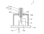
はじめに、光源装置1の構成について説明する。図1は、実施の形態1に係る光源装置の構成を示す外観斜視図である。図2は、図1に示した光源装置のII−II線における断面図である。
次に、光源装置1の製造方法について説明する。図4は、実施の形態1に係る光源装置1の製造手順の一例を示すフローチャート4である。なお、以下に示す光源装置1の製造手順では、一例として上述した構成1の場合について説明する。
以上、本実施の形態に係る光源装置1によると、ステム10とキャップ12と、キャップ12の開口部12aの縁に接合された第1のフェルール14bにより、光源装置1を気密封止することができる。また、第1の導光素子14aの周囲に第1のフェルール14bが接合されているので、第1の導光素子14aと発光部11との位置を精度よく合わせることができる。これにより、発光部11から出力されるレーザ光を第1の導光素子14aに容易に導光することができる。
次に、実施の形態2に係る光源装置2について説明する。図5は、本実施の形態に係る光源装置2の構成を示す断面図である。図6は、本実施の形態に係る光源装置2の使用方法の一例を示す概略図である。
10 ステム(基板)
11 発光部
12 キャップ
14 第1の導光部
14a 第1の導光素子
14b 第1のフェルール
16 リード端子
20a 接合部材(第2の接合部材)
20b 接合部材(第1の接合部材)
30 第2の導光部
30a 第2の導光素子
30b 第2のフェルール
32 スリーブ
Claims (6)
- 基板上に搭載された発光部と、
前記発光部を覆うように前記基板に接合されたキャップと、
前記発光部から出射した光を前記キャップの外に導光する第1の導光素子と、
前記第1の導光素子の周囲に設けられた第1のフェルールとを備え、
前記キャップは、前記発光部と対向する位置に開口部を有し、
前記第1のフェルールは、前記開口部に挿入された状態で前記開口部の縁と接合されている
光源装置。 - 前記第1のフェルールは、第1の接合部材により前記開口部の縁に接合されている
請求項1に記載の光源装置。 - 前記第1のフェルールは、前記第1の接合部材よりも融点が高い第2の接合部材により前記第1の導光素子と接合されている
請求項1または2に記載の光源装置。 - 前記光源装置は、前記第1の導光素子から出射した光を導光する第2の導光素子を備え、
前記第2の導光素子は、前記第1の導光素子と対向する端部側の周囲に、第2のフェルールを有する
請求項1〜3のいずれか1項に記載の光源装置。 - 前記第2のフェルールは、スリーブにより前記第1のフェルールに着脱可能に接続されている
請求項4に記載の光源装置。 - 前記第1の導光素子の一端は前記発光部と対向し、前記発光部と対向する前記第1の導光素子の先端は、前記発光部に向かって細くなっている
請求項1〜5のいずれか1項に記載の光源装置。
Priority Applications (4)
| Application Number | Priority Date | Filing Date | Title |
|---|---|---|---|
| JP2016047406A JP2017163041A (ja) | 2016-03-10 | 2016-03-10 | 光源装置 |
| DE102017104855.3A DE102017104855A1 (de) | 2016-03-10 | 2017-03-08 | Lichtquellenvorrichtung |
| US15/454,404 US10557997B2 (en) | 2016-03-10 | 2017-03-09 | Light source device |
| CN201720228898.7U CN206682672U (zh) | 2016-03-10 | 2017-03-09 | 光源装置 |
Applications Claiming Priority (1)
| Application Number | Priority Date | Filing Date | Title |
|---|---|---|---|
| JP2016047406A JP2017163041A (ja) | 2016-03-10 | 2016-03-10 | 光源装置 |
Publications (1)
| Publication Number | Publication Date |
|---|---|
| JP2017163041A true JP2017163041A (ja) | 2017-09-14 |
Family
ID=59700857
Family Applications (1)
| Application Number | Title | Priority Date | Filing Date |
|---|---|---|---|
| JP2016047406A Pending JP2017163041A (ja) | 2016-03-10 | 2016-03-10 | 光源装置 |
Country Status (4)
| Country | Link |
|---|---|
| US (1) | US10557997B2 (ja) |
| JP (1) | JP2017163041A (ja) |
| CN (1) | CN206682672U (ja) |
| DE (1) | DE102017104855A1 (ja) |
Cited By (1)
| Publication number | Priority date | Publication date | Assignee | Title |
|---|---|---|---|---|
| JP2020102583A (ja) * | 2018-12-25 | 2020-07-02 | 京セラ株式会社 | 光学装置用パッケージおよび光学装置ならびに光学装置の製造方法 |
Citations (24)
| Publication number | Priority date | Publication date | Assignee | Title |
|---|---|---|---|---|
| JPS5896505U (ja) * | 1981-12-22 | 1983-06-30 | 日立電線株式会社 | 光結合器 |
| JPS5910289A (ja) * | 1982-07-09 | 1984-01-19 | Hitachi Ltd | 半導体装置 |
| JPS59193080A (ja) * | 1983-04-15 | 1984-11-01 | Hitachi Ltd | 発光半導体装置 |
| JPS61148410A (ja) * | 1984-12-24 | 1986-07-07 | Toshiba Corp | 光半導体装置 |
| JPS63133683A (ja) * | 1986-11-26 | 1988-06-06 | Fujitsu Ltd | 半導体発光装置 |
| JPS63182616A (ja) * | 1987-01-23 | 1988-07-27 | Toshiba Corp | 光フアイバ−結合装置 |
| JPS63155659U (ja) * | 1987-03-31 | 1988-10-12 | ||
| JPH0267508A (ja) * | 1988-09-02 | 1990-03-07 | Nippon Telegr & Teleph Corp <Ntt> | 光ファイバ固定法 |
| JPH02151817A (ja) * | 1988-12-05 | 1990-06-11 | Matsushita Electric Ind Co Ltd | 発光素子モジュール |
| JPH02151818A (ja) * | 1988-12-05 | 1990-06-11 | Matsushita Electric Ind Co Ltd | 発光素子モジュール |
| JPH02151819A (ja) * | 1988-12-05 | 1990-06-11 | Matsushita Electric Ind Co Ltd | 発光素子モジュール |
| JPH02151820A (ja) * | 1988-12-05 | 1990-06-11 | Matsushita Electric Ind Co Ltd | 発光素子モジュール |
| JPH03235904A (ja) * | 1990-02-13 | 1991-10-21 | Sumitomo Electric Ind Ltd | 光半導体モジュールの構造 |
| JPH0429208A (ja) * | 1990-05-25 | 1992-01-31 | Nec Corp | 半導体レーザモジュール |
| JPH0511463U (ja) * | 1991-07-23 | 1993-02-12 | 株式会社島津製作所 | 発光ダイオード |
| JPH0784160A (ja) * | 1993-06-30 | 1995-03-31 | Anritsu Corp | 光素子モジュール及びそれの組立方法 |
| JPH0843690A (ja) * | 1994-07-28 | 1996-02-16 | Hitachi Ltd | 半導体光モジュール |
| JPH08508135A (ja) * | 1993-03-25 | 1996-08-27 | ブリテイッシュ・テレコミュニケーションズ・パブリック・リミテッド・カンパニー | レーザ |
| JP2002250844A (ja) * | 2001-02-23 | 2002-09-06 | Kyocera Corp | ファイバスタブ及びそれを用いた光半導体モジュール |
| US20020196824A1 (en) * | 2001-06-15 | 2002-12-26 | Hans-Ludwig Althaus | Optoelectronic laser module |
| JP2003520991A (ja) * | 2000-01-18 | 2003-07-08 | インフィネオン テクノロジーズ アクチエンゲゼルシャフト | 内部光学導波管を有する光学送受信モジュール |
| JP2005301180A (ja) * | 2004-04-16 | 2005-10-27 | Sumitomo Metal Mining Co Ltd | 光モジュール、光モジュール気密封止方法および光モジュール用金属フェルール付光ファイバ |
| JP2009294419A (ja) * | 2008-06-05 | 2009-12-17 | Sumitomo Electric Ind Ltd | 光サブアセンブリ及び光データリンク |
| JP2014115503A (ja) * | 2012-12-11 | 2014-06-26 | Yazaki Corp | 光通信モジュール |
Family Cites Families (13)
| Publication number | Priority date | Publication date | Assignee | Title |
|---|---|---|---|---|
| JP2002261265A (ja) * | 2001-03-06 | 2002-09-13 | Sumitomo Electric Ind Ltd | 光通信装置 |
| JP3937911B2 (ja) * | 2002-05-10 | 2007-06-27 | 住友電気工業株式会社 | 光送受信モジュール及びこれを用いた光通信システム |
| JP4151355B2 (ja) * | 2002-08-30 | 2008-09-17 | 住友電気工業株式会社 | 発光モジュール |
| EP1543365A1 (de) * | 2002-09-23 | 2005-06-22 | Huber+Suhner Ag | Anschlussvorrichtung zum lösbaren verbinden wenigstens eines lichtwellenleiters mit wenigstens einem optoelektronischen bauelement sowie verfahren zum montieren einer solchen anschlussvorrichtung |
| US7348097B2 (en) * | 2003-06-17 | 2008-03-25 | Medtronic, Inc. | Insulative feed through assembly for electrochemical devices |
| JP4306595B2 (ja) * | 2004-11-22 | 2009-08-05 | 住友電気工業株式会社 | 光モジュール |
| US7433115B2 (en) * | 2004-12-15 | 2008-10-07 | Nichia Corporation | Light emitting device |
| US7665901B2 (en) * | 2006-02-17 | 2010-02-23 | Telescent Inc. | Protective fiber optic union adapters |
| US8733996B2 (en) * | 2010-05-17 | 2014-05-27 | Sharp Kabushiki Kaisha | Light emitting device, illuminating device, and vehicle headlamp |
| US8611708B2 (en) * | 2010-11-18 | 2013-12-17 | LGS Innovations LLC | Optical apparatus having improved resistance to thermal damage |
| JP5589007B2 (ja) | 2012-01-18 | 2014-09-10 | シャープ株式会社 | 発光装置、照明装置および車両用前照灯 |
| US9848761B2 (en) * | 2013-03-15 | 2017-12-26 | Research & Development International, Inc. | Method and apparatus for fiberscope employing single fiber bundle for co-propagation of image and illumination |
| JP6067629B2 (ja) | 2014-07-28 | 2017-01-25 | シャープ株式会社 | 発光装置、照明装置および車両用前照灯 |
-
2016
- 2016-03-10 JP JP2016047406A patent/JP2017163041A/ja active Pending
-
2017
- 2017-03-08 DE DE102017104855.3A patent/DE102017104855A1/de not_active Withdrawn
- 2017-03-09 CN CN201720228898.7U patent/CN206682672U/zh not_active Expired - Fee Related
- 2017-03-09 US US15/454,404 patent/US10557997B2/en not_active Expired - Fee Related
Patent Citations (24)
| Publication number | Priority date | Publication date | Assignee | Title |
|---|---|---|---|---|
| JPS5896505U (ja) * | 1981-12-22 | 1983-06-30 | 日立電線株式会社 | 光結合器 |
| JPS5910289A (ja) * | 1982-07-09 | 1984-01-19 | Hitachi Ltd | 半導体装置 |
| JPS59193080A (ja) * | 1983-04-15 | 1984-11-01 | Hitachi Ltd | 発光半導体装置 |
| JPS61148410A (ja) * | 1984-12-24 | 1986-07-07 | Toshiba Corp | 光半導体装置 |
| JPS63133683A (ja) * | 1986-11-26 | 1988-06-06 | Fujitsu Ltd | 半導体発光装置 |
| JPS63182616A (ja) * | 1987-01-23 | 1988-07-27 | Toshiba Corp | 光フアイバ−結合装置 |
| JPS63155659U (ja) * | 1987-03-31 | 1988-10-12 | ||
| JPH0267508A (ja) * | 1988-09-02 | 1990-03-07 | Nippon Telegr & Teleph Corp <Ntt> | 光ファイバ固定法 |
| JPH02151817A (ja) * | 1988-12-05 | 1990-06-11 | Matsushita Electric Ind Co Ltd | 発光素子モジュール |
| JPH02151818A (ja) * | 1988-12-05 | 1990-06-11 | Matsushita Electric Ind Co Ltd | 発光素子モジュール |
| JPH02151819A (ja) * | 1988-12-05 | 1990-06-11 | Matsushita Electric Ind Co Ltd | 発光素子モジュール |
| JPH02151820A (ja) * | 1988-12-05 | 1990-06-11 | Matsushita Electric Ind Co Ltd | 発光素子モジュール |
| JPH03235904A (ja) * | 1990-02-13 | 1991-10-21 | Sumitomo Electric Ind Ltd | 光半導体モジュールの構造 |
| JPH0429208A (ja) * | 1990-05-25 | 1992-01-31 | Nec Corp | 半導体レーザモジュール |
| JPH0511463U (ja) * | 1991-07-23 | 1993-02-12 | 株式会社島津製作所 | 発光ダイオード |
| JPH08508135A (ja) * | 1993-03-25 | 1996-08-27 | ブリテイッシュ・テレコミュニケーションズ・パブリック・リミテッド・カンパニー | レーザ |
| JPH0784160A (ja) * | 1993-06-30 | 1995-03-31 | Anritsu Corp | 光素子モジュール及びそれの組立方法 |
| JPH0843690A (ja) * | 1994-07-28 | 1996-02-16 | Hitachi Ltd | 半導体光モジュール |
| JP2003520991A (ja) * | 2000-01-18 | 2003-07-08 | インフィネオン テクノロジーズ アクチエンゲゼルシャフト | 内部光学導波管を有する光学送受信モジュール |
| JP2002250844A (ja) * | 2001-02-23 | 2002-09-06 | Kyocera Corp | ファイバスタブ及びそれを用いた光半導体モジュール |
| US20020196824A1 (en) * | 2001-06-15 | 2002-12-26 | Hans-Ludwig Althaus | Optoelectronic laser module |
| JP2005301180A (ja) * | 2004-04-16 | 2005-10-27 | Sumitomo Metal Mining Co Ltd | 光モジュール、光モジュール気密封止方法および光モジュール用金属フェルール付光ファイバ |
| JP2009294419A (ja) * | 2008-06-05 | 2009-12-17 | Sumitomo Electric Ind Ltd | 光サブアセンブリ及び光データリンク |
| JP2014115503A (ja) * | 2012-12-11 | 2014-06-26 | Yazaki Corp | 光通信モジュール |
Cited By (2)
| Publication number | Priority date | Publication date | Assignee | Title |
|---|---|---|---|---|
| JP2020102583A (ja) * | 2018-12-25 | 2020-07-02 | 京セラ株式会社 | 光学装置用パッケージおよび光学装置ならびに光学装置の製造方法 |
| JP7039450B2 (ja) | 2018-12-25 | 2022-03-22 | 京セラ株式会社 | 光学装置用パッケージおよび光学装置ならびに光学装置の製造方法 |
Also Published As
| Publication number | Publication date |
|---|---|
| CN206682672U (zh) | 2017-11-28 |
| US10557997B2 (en) | 2020-02-11 |
| US20170261697A1 (en) | 2017-09-14 |
| DE102017104855A1 (de) | 2017-09-14 |
Similar Documents
| Publication | Publication Date | Title |
|---|---|---|
| US4615031A (en) | Injection laser packages | |
| GB2124402A (en) | Injection laser packages | |
| US10978851B2 (en) | Package for optical device and optical device module | |
| JP2018049174A (ja) | 光源装置 | |
| US10411167B2 (en) | Semiconductor light emitting apparatus, stem part | |
| US10557997B2 (en) | Light source device | |
| JP2019053313A (ja) | 光学素子モジュール | |
| JPH0267508A (ja) | 光ファイバ固定法 | |
| JP2005165200A (ja) | 光デバイスとその製造方法 | |
| WO2017010025A1 (ja) | レーザモジュール | |
| JP2005121921A (ja) | 光モジュール用レンズホルダ、光モジュールおよび、光モジュールの組立方法 | |
| JP2009152339A (ja) | 光デバイス及びその製造方法 | |
| US20070031093A1 (en) | Optical module with lens holder projection-welded to butterfly package | |
| JP2970635B2 (ja) | 半導体レーザーモジュール及び金属フェルール | |
| JP5419780B2 (ja) | 光ファイバ固定用フェルール及びそれを用いた光ファイバ固定具 | |
| JP2007298643A (ja) | 光素子モジュールおよびその製造方法 | |
| JP2009003309A (ja) | 光モジュールの組立方法及び光モジュール | |
| JP4969834B2 (ja) | 光半導体モジュール及び光半導体モジュールの製造方法 | |
| JP7059675B2 (ja) | 半導体発光装置およびその製造方法 | |
| TWI220808B (en) | Connector with laser diode and manufacturing method thereof | |
| JPS61136275A (ja) | 光素子パツケ−ジ | |
| JPS62211965A (ja) | 光半導体装置 | |
| JPS6271910A (ja) | 半導体レ−ザ装置 | |
| JP2009092899A (ja) | 光モジュールの組立方法及び光モジュール | |
| JP2016218203A (ja) | 光モジュール |
Legal Events
| Date | Code | Title | Description |
|---|---|---|---|
| A621 | Written request for application examination |
Free format text: JAPANESE INTERMEDIATE CODE: A621 Effective date: 20181217 |
|
| A977 | Report on retrieval |
Free format text: JAPANESE INTERMEDIATE CODE: A971007 Effective date: 20191210 |
|
| A131 | Notification of reasons for refusal |
Free format text: JAPANESE INTERMEDIATE CODE: A131 Effective date: 20200107 |
|
| A521 | Request for written amendment filed |
Free format text: JAPANESE INTERMEDIATE CODE: A523 Effective date: 20200220 |
|
| A02 | Decision of refusal |
Free format text: JAPANESE INTERMEDIATE CODE: A02 Effective date: 20200630 |