JP2017164792A - Molding method and apparatus - Google Patents
Molding method and apparatus Download PDFInfo
- Publication number
- JP2017164792A JP2017164792A JP2016053686A JP2016053686A JP2017164792A JP 2017164792 A JP2017164792 A JP 2017164792A JP 2016053686 A JP2016053686 A JP 2016053686A JP 2016053686 A JP2016053686 A JP 2016053686A JP 2017164792 A JP2017164792 A JP 2017164792A
- Authority
- JP
- Japan
- Prior art keywords
- stay
- mold
- convex
- concave
- shape
- Prior art date
- Legal status (The legal status is an assumption and is not a legal conclusion. Google has not performed a legal analysis and makes no representation as to the accuracy of the status listed.)
- Pending
Links
Images


Classifications
-
- B—PERFORMING OPERATIONS; TRANSPORTING
- B21—MECHANICAL METAL-WORKING WITHOUT ESSENTIALLY REMOVING MATERIAL; PUNCHING METAL
- B21D—WORKING OR PROCESSING OF SHEET METAL OR METAL TUBES, RODS OR PROFILES WITHOUT ESSENTIALLY REMOVING MATERIAL; PUNCHING METAL
- B21D37/00—Tools as parts of machines covered by this subclass
- B21D37/10—Die sets; Pillar guides
-
- B—PERFORMING OPERATIONS; TRANSPORTING
- B21—MECHANICAL METAL-WORKING WITHOUT ESSENTIALLY REMOVING MATERIAL; PUNCHING METAL
- B21D—WORKING OR PROCESSING OF SHEET METAL OR METAL TUBES, RODS OR PROFILES WITHOUT ESSENTIALLY REMOVING MATERIAL; PUNCHING METAL
- B21D24/00—Special deep-drawing arrangements in, or in connection with, presses
- B21D24/04—Blank holders; Mounting means therefor
-
- B—PERFORMING OPERATIONS; TRANSPORTING
- B21—MECHANICAL METAL-WORKING WITHOUT ESSENTIALLY REMOVING MATERIAL; PUNCHING METAL
- B21D—WORKING OR PROCESSING OF SHEET METAL OR METAL TUBES, RODS OR PROFILES WITHOUT ESSENTIALLY REMOVING MATERIAL; PUNCHING METAL
- B21D24/00—Special deep-drawing arrangements in, or in connection with, presses
- B21D24/16—Additional equipment in association with the tools, e.g. for shearing, for trimming
-
- B—PERFORMING OPERATIONS; TRANSPORTING
- B21—MECHANICAL METAL-WORKING WITHOUT ESSENTIALLY REMOVING MATERIAL; PUNCHING METAL
- B21D—WORKING OR PROCESSING OF SHEET METAL OR METAL TUBES, RODS OR PROFILES WITHOUT ESSENTIALLY REMOVING MATERIAL; PUNCHING METAL
- B21D53/00—Making other particular articles
- B21D53/86—Making other particular articles other parts for bicycles or motorcycles
Landscapes
- Engineering & Computer Science (AREA)
- Mechanical Engineering (AREA)
- Cooling, Air Intake And Gas Exhaust, And Fuel Tank Arrangements In Propulsion Units (AREA)
- Shaping Metal By Deep-Drawing, Or The Like (AREA)
Abstract
【課題】ワークに膨出部を成形して中空湾曲成形品を得るに際し、特に生産歩留まりを向上させる。【解決手段】凸型であるウレタン成形型28の、凹型である上型30に臨む上型側頂部には傾斜面42が形成される。傾斜面42の傾斜方向は、ブランクホルダ26の第1ステー38側から第2ステー40側に向かう方向である。この傾斜面42により、ウレタン成形型28は逃げ部が形成された形状となっている。ブランクホルダ26を上型30が覆ったとき、傾斜面42(逃げ部)は、上型30に形成された凹部50に位置する。【選択図】図1[PROBLEMS] To improve a production yield particularly when a bulging portion is formed on a workpiece to obtain a hollow curved molded product. An inclined surface is formed on an upper mold side top of a urethane mold that is a convex mold and an upper mold that is a concave mold. The inclination direction of the inclined surface 42 is a direction from the first stay 38 side of the blank holder 26 toward the second stay 40 side. Due to the inclined surface 42, the urethane mold 28 has a shape in which an escape portion is formed. When the upper mold 30 covers the blank holder 26, the inclined surface 42 (relief part) is located in the recess 50 formed in the upper mold 30. [Selection] Figure 1
Description
本発明は、成形方法及びその装置に関し、一層詳細には、中空湾曲成形品を得るのに適した成形方法及びその装置に関する。 The present invention relates to a molding method and apparatus, and more particularly to a molding method and apparatus suitable for obtaining a hollow curved molded product.
自動二輪車の燃料タンクは、燃料を収容するべく中空体からなり、且つ意匠性を良好とするとともに空気抵抗の低減を図るべく、湾曲形状をなしている。場合によっては、意匠性を一層向上させるべく、外表面に凸部が形成されることもある。 The fuel tank of a motorcycle is made of a hollow body to accommodate fuel, and has a curved shape in order to improve design and reduce air resistance. In some cases, a convex portion may be formed on the outer surface in order to further improve the design.
燃料タンクは、例えば、特許文献1に記載されるように、車幅方向の右半分部位をなす第1半製品と、左半分部位をなす第2半製品とをプレス成形によって個別に作製し、その後、第1半製品と第2半製品を溶接等で接合することで作製される。 For example, as described in Patent Document 1, the fuel tank is manufactured separately by press molding a first semi-finished product that forms a right half portion in the vehicle width direction and a second semi-finished product that forms a left half portion, Thereafter, the first semi-finished product and the second semi-finished product are produced by joining by welding or the like.
この場合、接合作業が不可欠であるため、作業工数を低減することが容易ではない。また、接合部から漏洩が起こることを防止するための管理項目が多く、煩雑である。 In this case, since joining work is indispensable, it is not easy to reduce work man-hours. Moreover, there are many management items for preventing leakage from the joint, which is complicated.
燃料タンクの別の製造方法としては、バルジ成形が挙げられる。バルジ成形においては、変形する凸型が用いられる。従来技術では、例えば、特許文献2に記載されるように、該凸型として中空体を用いるとともに、その中空内部に流体を給排することで該凸型を変形させることが一般的に行われている。
Another method for manufacturing a fuel tank is bulge molding. In bulge forming, a convex mold that deforms is used. In the prior art, for example, as described in
すなわち、凸型を変形させてワークを押圧するとともに、変形した凸型を、変形するワークごと凹型の凹部に進入させる。その結果として、外表面が凹部の形状に対応する形状に成形された燃料タンクが得られるに至る。 That is, the convex shape is deformed to press the work, and the deformed convex shape is caused to enter the concave concave portion together with the deformed work. As a result, a fuel tank whose outer surface is shaped into a shape corresponding to the shape of the recess is obtained.
特許文献2に記載されるバルジ成形では、ワークの肉が大きく延展される。このように大きな肉の延展を伴う成形を行う場合、燃料タンクに、肉厚が設計肉厚よりも小さな部位が形成されることがある。この場合、規格外品として分別すればよいが、規格外品の個数が多く生産歩留まりが低い場合、コストの低廉化を図ることが困難である。
In the bulge forming described in
しかも、このバルジ成形では、凸型の中空内部に流体を導入して該凸型を変形させるようにしている。この場合、凸型の変形能力、換言すれば、形状追従性はさほど高くなく、このために燃料タンクに微小な凹凸を形成することが容易ではない。すなわち、意匠性に優れた燃料タンクを成形することが容易ではないとの指摘がある。 Moreover, in this bulge molding, a fluid is introduced into the convex hollow interior to deform the convex mold. In this case, the convex deformation capability, in other words, the shape following capability is not so high, and it is not easy to form minute irregularities in the fuel tank. That is, it is pointed out that it is not easy to mold a fuel tank having excellent design properties.
本発明は上記した問題を解決するためになされたもので、生産歩留まりを向上し得、さらに、美観に優れた中空湾曲成形品を得ることが可能な成形方法及びその装置を提供することを目的とする。 The present invention has been made to solve the above-described problems, and it is an object of the present invention to provide a molding method and apparatus capable of improving a production yield and further capable of obtaining a hollow curved molded article having an excellent aesthetic appearance. And
前記の目的を達成するために、本発明に係る成形方法は、ワークの第1端部、第2端部を、ブランクホルダの第1ステー、第2ステーでそれぞれを支持する工程と、
前記第1ステー、前記第2ステーのそれぞれに、凹部が設けられた凹型の第1被支持部、第2被支持部を支持する工程と、
変形可能であり、前記第1ステー側端部に、前記ブランクホルダから前記凹型に向かう方向に対して前記第2ステー側に向かうように傾斜した傾斜面が形成された凸型を、前記傾斜面の、前記凹型に臨む凹型側頂部が、前記凹部に位置した状態から変形させ、前記第1ステーと前記第2ステーの間から突出した部位で前記ワークの前記第1端部と前記第2端部の間を押圧するとともに、前記凸型と前記凹型の凹部で挟むことで前記ワークに膨出部を成形する工程と、
前記膨出部と前記第1端部との間の部位を成形する工程と、
を有することを特徴とする。
In order to achieve the above object, the forming method according to the present invention includes a step of supporting the first end and the second end of the work with the first stay and the second stay of the blank holder, respectively.
A step of supporting a concave first supported portion and a second supported portion provided with a recess in each of the first stay and the second stay;
A convex mold that is deformable and has an inclined surface that is inclined toward the second stay side with respect to a direction from the blank holder toward the concave mold at the first stay side end portion, The concave side top portion facing the concave shape is deformed from a state where it is located in the concave portion, and the first end portion and the second end of the workpiece at a portion protruding from between the first stay and the second stay. A step of forming a bulging portion on the workpiece by pressing between the convex portions and sandwiching between the convex and concave portions,
Forming a portion between the bulging portion and the first end;
It is characterized by having.
また、本発明に係る成形装置は、ワークの第1端部、第2端部のそれぞれを支持する第1ステー、第2ステーが設けられたブランクホルダと、
前記第1ステーと前記第2ステーの間から突出して前記ワークの前記第1端部と前記第2端部の間を押圧し、前記ワークに膨出部を形成する変形可能な凸型と、
前記第1ステー、前記第2ステーのそれぞれに支持される第1被支持部、第2被支持部を有し、前記第1被支持部と前記第2被支持部の間に、前記凸型とともに前記膨出部を成形するための凹部が設けられた凹型と、
を有し、
前記凸型の前記第1ステー側端部に、前記ブランクホルダから前記凹型に向かう方向に対して前記第2ステー側に向かうように傾斜した傾斜面が形成され、
前記傾斜面の、前記凹型に臨む凹型側頂部が、前記凹部に位置することを特徴とする。
Further, the molding apparatus according to the present invention includes a blank holder provided with a first stay and a second stay for supporting the first end and the second end of the workpiece,
A deformable convex shape that protrudes from between the first stay and the second stay and presses between the first end and the second end of the work to form a bulge on the work,
A first supported portion and a second supported portion that are supported by the first stay and the second stay, respectively, and the convex shape is provided between the first supported portion and the second supported portion; And a concave mold provided with a recess for forming the bulging portion,
Have
An inclined surface that is inclined toward the second stay side with respect to a direction from the blank holder toward the concave shape is formed at the first stay side end of the convex shape,
The concave side apex of the inclined surface facing the concave shape is located in the concave portion.
従来技術においては、凸型に上記したような傾斜面が設けられていない。本発明者は、このことに基づき、ワークに膨出部を成形するときに該ワークの第1端部と膨出部との間の部位が凸型と凹型に挟まれて拘束されると推察した。すなわち、この拘束によって当該部位が延展することが困難となり、この分、膨出部の肉厚が小さくなる傾向があると考えた。 In the prior art, the inclined surface as described above is not provided on the convex mold. Based on this, the present inventor presumes that when the bulging portion is formed on the workpiece, the portion between the first end portion and the bulging portion of the workpiece is sandwiched between the convex shape and the concave shape and restrained. did. That is, it was considered that the restriction made it difficult for the part to extend, and the thickness of the bulging portion tended to be reduced accordingly.
これに対し、本発明においては、変形可能な凸型に傾斜面を設けるとともに、該傾斜面の、凹型に臨む凹型側頂部を、凹型に形成された凹部に位置させるようにしている。本発明者の鋭意検討によれば、この構成を採用することにより、ワークに膨出部を成形するとき、ワークの第1端部と膨出部との間の部位が凸型と凹型に挟まれること、換言すれば、拘束されることが回避される。このため、当該部位の肉が膨出部に向かって延展(流動)することが容易であるので、設計肉厚を十分に満足する膨出部が成形される。 On the other hand, in the present invention, an inclined surface is provided on a deformable convex shape, and the concave side top portion of the inclined surface facing the concave shape is positioned in a concave portion formed in the concave shape. According to the earnest study of the present inventor, by adopting this configuration, when the bulging portion is formed on the workpiece, the portion between the first end portion of the workpiece and the bulging portion is sandwiched between the convex shape and the concave shape. In other words, being restrained is avoided. For this reason, it is easy for the flesh of the said part to extend (flow) toward the bulging part, Therefore The bulging part which fully satisfies design thickness is shape | molded.
以上の対比から諒解されるように、凸型に、ワークの第1端部と膨出部との間の部位を拘束しない逃げ部を形成することにより、肉厚が設計肉厚を満足する中空湾曲成形品が容易に得られるようになる。この結果として規格外品の個数が低減するので、生産歩留まりが向上する。これにより、コストの低廉化を図ることができる。 As can be understood from the above comparison, a hollow portion whose wall thickness satisfies the design wall thickness is formed by forming a relief portion in the convex shape that does not restrain the portion between the first end portion and the bulging portion of the workpiece. A curved molded product can be easily obtained. As a result, the number of non-standard products is reduced, so that the production yield is improved. Thereby, cost reduction can be achieved.
しかも、溶接等の接合作業を行う必要がないので、中空湾曲成形品に接合線が形成されることがない。従って、美観に優れたものとなる。加えて、漏洩を回避するための管理を行う必要がないので、簡便である。 And since it is not necessary to perform joining operations, such as welding, a joining line is not formed in a hollow curve molded article. Therefore, it is excellent in aesthetics. In addition, since it is not necessary to perform management for avoiding leakage, it is convenient.
前記膨出部に凸部を成形するようにしてもよい。この場合、前記凹型に凸部成形部を設けるようにすればよい。 A convex portion may be formed on the bulging portion. In this case, a convex molding part may be provided in the concave mold.
上記したように、本発明によれば膨出部の肉厚が十分なものとなる。従って、この膨出部からさらに凸部を成形するようにした場合であっても、膨出部及び凸部に十分な肉厚が確保される。凸部によって意匠性が向上するので、美観に優れた中空湾曲成形品を得ることが容易となる。 As described above, according to the present invention, the wall thickness of the bulging portion is sufficient. Therefore, even when the convex portion is further formed from the bulging portion, a sufficient thickness is secured in the bulging portion and the convex portion. Since the design is improved by the convex portion, it is easy to obtain a hollow curved molded product having an excellent aesthetic appearance.
凸型は、中実体であることが好ましい。この場合、該凸型が凹型の形状に倣って変形する。すなわち、形状追従性に優れる。従って、中空湾曲成形品に微小な凹凸を形成することが可能となるので、該中空湾曲成形品が意匠性に優れたものとなる。 The convex shape is preferably a solid body. In this case, the convex mold deforms following the concave shape. That is, it is excellent in shape followability. Therefore, since it is possible to form minute irregularities on the hollow curved molded product, the hollow curved molded product is excellent in design.
なお、前記ワークから得られる中空湾曲成形品の好適な一例としては、自動二輪車の燃料タンクが挙げられる。 A preferable example of the hollow curved molded product obtained from the workpiece is a fuel tank of a motorcycle.
本発明によれば、変形可能な凸型に傾斜面(逃げ部)を設け、該傾斜面を、凹型に形成された凹部に位置させるようにしているので、ワークに膨出部を成形するとき、ワークの第1端部と膨出部との間の部位が凸型と凹型に挟まれて拘束されることが回避される。このため、ワークの肉が延展されるとき、当該部位の肉が膨出部に向かって容易に流動するので、設計肉厚を十分に満足する膨出部が成形される。すなわち、規格外品の個数が低減する。従って、生産歩留まりの向上と、コストの低廉化を図ることができる。 According to the present invention, the deformable convex mold is provided with the inclined surface (relief portion), and the inclined surface is positioned in the concave portion formed in the concave mold. It is avoided that the portion between the first end portion and the bulging portion of the work is sandwiched and restrained between the convex shape and the concave shape. For this reason, when the flesh of the work is extended, the flesh of the portion easily flows toward the bulging portion, so that the bulging portion that sufficiently satisfies the design wall thickness is formed. That is, the number of non-standard products is reduced. Therefore, the production yield can be improved and the cost can be reduced.
しかも、溶接等の接合作業を行う必要がないので、成形品は、接合線が形成されていない美観に優れたものとなる。加えて、接合部から漏洩を回避するための管理を行う必要がないので、簡便である。 And since it is not necessary to perform joining operations, such as welding, a molded article becomes the thing excellent in the beauty | look in which the joining line is not formed. In addition, it is not necessary to perform management for avoiding leakage from the joint portion, which is convenient.
以下、本発明に係る成形方法につき、それを実施するための成形装置との関係で好適な実施の形態を挙げ、添付の図面を参照して詳細に説明する。なお、以下における「下」、「上」、「左」及び「右」は、図面中の下方、上方、左方及び右方に対応する。 DETAILED DESCRIPTION OF THE PREFERRED EMBODIMENTS Hereinafter, preferred embodiments of the molding method according to the present invention will be described in detail in relation to a molding apparatus for carrying out the method, with reference to the accompanying drawings. In the following, “lower”, “upper”, “left”, and “right” correspond to lower, upper, left, and right sides in the drawing.
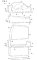
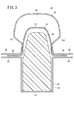
図1〜図3は、それぞれ、本実施の形態に係るバルジ成形装置10(成形装置)の要部分解斜視図、概略側面断面図、概略正面断面図である。このバルジ成形装置10は、ワークである予備成形体12を、自動二輪車用の燃料タンクT(図9参照)、すなわち、中空湾曲成形品に成形するためのものである。
1 to 3 are an exploded perspective view, a schematic side cross-sectional view, and a schematic front cross-sectional view, respectively, of a main part of a bulge forming apparatus 10 (forming apparatus) according to the present embodiment. The
先ず予備成形体12につき概略説明すると、該予備成形体12は、板材が長手方向に沿って湾曲され、長手方向に直交する方向の断面が略Ω字形状をなす中空湾曲体である。すなわち、予備成形体12は、長尺で且つ頂部が湾曲した本体部14と、該本体部14の下端から水平方向外方に向かって突出した第1鍔部16、第2鍔部18とを有する。この中の本体部14は、左方から右方に向かうに従って高さが小さくなる。換言すれば、出発材の形状と、出発材から予備成形体12への成形形状は、長手方向に沿って延在するに従って漸次的に高さが変化する本体部14が得られるように設定されている。
First, the preformed
以下、予備成形体12の長手方向の各端部を第1端部、第2端部と指称し、その参照符号を20、22とする。第1端部20は、高さが大きい左方側の端部であり、第1鍔部16、本体部14、第2鍔部18の左端部が含まれる。一方の第2端部22は高さが小さい右方側の端部であり、第1鍔部16、本体部14、第2鍔部18の右端部が含まれる。
Hereinafter, the respective end portions in the longitudinal direction of the preformed
第1端部20の頂部は略楕円形状に湾曲している。これに対し、第2端部22の頂部は略長方形形状をなしている。
The top of the
次に、バルジ成形装置10の構成につき説明する。このバルジ成形装置10は、下型24と、ブランクホルダ26と、凸型であるウレタン成形型28と、凹型である上型30とを有する。なお、図1〜図3において、下型24は頂面のみが示されている。
Next, the configuration of the
下型24及びウレタン成形型28は位置決め固定された固定型であり、一方、上型30は下型24に対して接近又は離間するように下降又は上昇する可動型である。すなわち、下型24は、上型30に対して相対的に上昇又は下降する。
The
ブランクホルダ26は中空体であり、略直方体形状をなす収容部32と、該収容部32の上端開口の長尺な2辺から外方に向かうように突出した第1長尺載置部34、第2長尺載置部36とを有する。さらに、第1長尺載置部34の左端から第2長尺載置部36の左端にかけて、アーチ形状に湾曲した第1ステー38が設けられる。同様に、第1長尺載置部34の右端から第2長尺載置部36の右端には、アーチ形状に湾曲した第2ステー40が設けられている。第1ステー38は、第2ステー40に比して高さが大きく設定される。
The
後述するように、第1長尺載置部34、第2長尺載置部36は、第1鍔部16、第2鍔部18をそれぞれ支持する。また、第1ステー38は第1端部20を支持し、第2ステー40は第2端部22を支持する。このため、第1ステー38の頂部は第1端部20の形状に対応して略楕円形状に湾曲し、第2ステー40の頂部は第2端部22の形状に対応して略長方形形状をなしている。
As will be described later, the first long mounting
ウレタン成形型28は、発泡ウレタン樹脂からなる中実体である(図2及び図3参照)。該ウレタン成形型28は、下型24に支持されるとともに、下部の大部分が収容部32に収容されている。このウレタン成形型28は、外力が付与されることに伴って変形する。
The
ウレタン成形型28の下部は幅狭の略直方体形状であり、上下方向、すなわち、ブランクホルダ26から上型30に向かう鉛直方向に沿って延在する。すなわち、鉛直方向に沿って延在する4個の側方端面は垂直壁である。これに対し、上部は、その第1ステー38(第1端部20)側端部で、第1ステー38側から第2ステー40(第2端部22)側に向かうようにして傾斜している。すなわち、ウレタン成形型28の左端面は、垂直壁に対して傾斜面42が一体的に連なるようにして形成されている。
The lower part of the urethane molding die 28 has a narrow, substantially rectangular parallelepiped shape, and extends in the vertical direction, that is, along the vertical direction from the
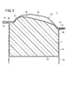
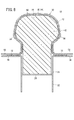
図4を参照して諒解されるように、従来技術に係るバルジ成形装置1を構成するウレタン成形型2の4個の側方端面は、下部であるか上部であるかに関わらず垂直壁である。一方、本実施の形態では、上記の傾斜面42(図1及び図2参照)が形成されることに伴い、ウレタン成形型28の上部が第2ステー40側に切り欠かれた形状となっている。このため、本実施の形態においては、ウレタン成形型28の上型側頂部(凹型側頂部)に逃げ部が形成されている。
As will be understood with reference to FIG. 4, the four side end surfaces of the
ウレタン成形型28の頂部は、長手方向に沿って、具体的には、ブランクホルダ26の第1ステー38側から第2ステー40側(予備成形体12の第1端部20側から第2端部22側)に向かうに従って、高さが漸次的に小さくなるように傾斜している。結局、ウレタン成形型28の頂部は、予備成形体12の本体部14の頂部の傾斜に対応している。
Specifically, the top of the
上型30は、変形したウレタン成形型28と押圧された予備成形体12が進入する凹部50が形成された凹型である。凹部50の形状は、燃料タンクTの形状に対応する。凹部50には、さらに、燃料タンクTに凸部52(図9参照)を形成するための凸部成形部54が両側方に設けられる。凹部50の容積は、第1ステー38に対応する側の端部で大きく、第2ステー40に対応する側の端部に向かうに従って小さくなっている。すなわち、第1ステー38側は自動二輪車の車体前方側、第2ステー40側は車体後方側を成形し、加工率は第1ステー38側が大きくなる。
The
上型30には、ブランクホルダ26の第1長尺載置部34、第2長尺載置部36、第1ステー38、第2ステー40にそれぞれ支持される第1鍔部押さえ部58、第2鍔部押さえ部60、第1被支持部62、第2被支持部64が設けられる。予備成形体12の第1鍔部16は第1長尺載置部34と第1鍔部押さえ部58に挟持され、第2鍔部18は第2長尺載置部36と第2鍔部押さえ部60に挟持される。さらに、第1端部20は第1ステー38と第1被支持部62に、第2端部22は第2ステー40と第2被支持部64に、それぞれ挟持される。
The
上型30は、特に図示していないが、凹部50が長手方向に沿って左右略半分に分割されている。すなわち、上型30は2個の分割型からなる。該2個の分割型は、成形を行うときには閉じられ、離型を行うときには開かれる。
Although the
また、上型30は、図示しない昇降機構(例えば、油圧シリンダ)が付勢されることによって下降又は上昇する。これにより、上型30がブランクホルダ26に保持された予備成形体12に対して接近又は離間する。
Further, the
本実施の形態に係るバルジ成形装置10は、基本的には以上のように構成されるものであり、次に、その作用効果につき、本実施の形態に係る成形方法との関係で説明する。
The
予備成形体12から燃料タンクTを作製するには、先ず、予備成形体12をブランクホルダ26に保持する。このためには、第1鍔部16、第2鍔部18、第1端部20、第2端部22のそれぞれを、第1長尺載置部34、第2長尺載置部36、第1ステー38、第2ステー40に載置する。この際、ウレタン成形型28の外表面が予備成形体12の内表面に当接している必要は特にない。
In order to produce the fuel tank T from the
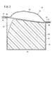
次に、前記昇降機構を付勢して上型30を下降する。上型30は所定の距離だけ下降し、分割型同士が閉じられた状態となるとともに、第1鍔部押さえ部58、第2鍔部押さえ部60、第1被支持部62、第2被支持部64が、第1鍔部16、第2鍔部18、第1端部20、第2端部22に着座する。これにより、図2及び図3に示す状態が形成される。図2に示すように、このとき、傾斜面42の上型側頂部、換言すれば、逃げ部が上型30の凹部50内に位置する。
Next, the
図4に示すように、従来技術においては、ウレタン成形型2に逃げ部が設けられていない。このため、高さが大きな第1ステー38側の端部の上型側頂部は、第1端部20の略直下に位置する。なお、図4では、理解を容易にするべく、図1〜図3に示される構成要素と同一の構成要素に同一の参照符号を付している。
As shown in FIG. 4, in the prior art, the
この状態で、上型30をさらに下降する。その結果、下型24及びウレタン成形型2が相対的に上昇する。この際、下型24の上端部は、ブランクホルダ26の収容部32に進入する。
In this state, the
ウレタン成形型2の相対的に上昇した部位は、第1ステー38と第2ステー40の間から突出し、下型24と予備成形体12に押圧されて変形する。従って、予備成形体12の内表面に対し、ウレタン成形型2からの押圧力が付与される。その結果、予備成形体12が凹部50の内表面側に向かって延展し始める。
The relatively raised portion of the
この際、予備成形体12の主に本体部14が凹部50に向かって延展することで体積が増加し、ウレタン成形型2が予備成形体12の延展した肉ごと凹部50に進入する。これにより、膨出部70の成形が開始される。
At this time, the
従来技術では、膨出部70の成形が開始されて若干の時間が経過した後、図5に示すように、変形したウレタン成形型2の第1ステー38側端部の上型側頂部が、予備成形体12の第1端部20と膨出部70との間の部位(以下、「連絡部位」と表記する)72に当接する。このため、連絡部位72がウレタン成形型2と上型30とで挟まれて拘束される。この状態では、連絡部位72の肉が流動することは困難である。
In the prior art, after some time has elapsed since the molding of the bulging
このようにして連絡部位72がウレタン成形型2と上型30で挟持されながら、ウレタン成形型2が継続して変形することで膨出部70のさらなる成形が行われる。従って、この場合、膨出部70の成形は張出成形となる。
In this way, the bulging
すなわち、従来技術では、予備成形体12が、連絡部位72が拘束された状態で本体部14が延展される。従って、連絡部位72の肉を膨出部70に向かって引っ張ることが困難となる。従来技術に係るバルジ成形装置1によって得られる燃料タンクTに、肉厚が設計肉厚よりも小さな部位が形成される理由はこのためであると推察される。
That is, in the prior art, the preformed
これに対し、本実施の形態では、図2から容易に諒解されるように、ウレタン成形型28に逃げ部が形成されており、このため、上型30が予備成形体12を覆った時点ではウレタン成形型28の上型側頂部が凹部50内に位置している。従って、この場合、上記と同様にして上型30が下降されたとき、ウレタン成形型28が変形して連絡部位72に当接するようになるまで、従来技術に比して長時間を要する。
On the other hand, in this embodiment, as can be easily understood from FIG. 2, an escape portion is formed in the
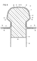
すなわち、本実施の形態においては、図6に示すように、連絡部位72がウレタン成形型28と上型30で挟持される前に膨出部70の成形が進行する。なお、相対的に上昇したウレタン成形型28の一部が第1ステー38と第2ステー40の間から突出するのは従来技術と同様である。
That is, in the present embodiment, as shown in FIG. 6, the bulging
この進行の際、連絡部位72の肉が容易に流動する。従って、膨出部70が絞り成形にて成形されることになる。このように、ウレタン成形型28の第1ステー38側端部の上型側頂部に、第2ステー40側に向かって傾斜する傾斜面42(逃げ部)を形成したことにより、肉の流動性を確保しながら膨出部70を成形することができる。
During this progression, the meat at the connecting
要するに、本実施の形態では、連絡部位72が拘束されることが回避されている。このため、本体部14がウレタン成形型28によって膨張することで膨出部70に成形される際、連絡部位72の肉が膨出部70側に引っ張られて容易に流動する。その結果、予備成形体12を延展するにも関わらず、設計肉厚を十分に満足する厚みの燃料タンクTが得られる。
In short, in the present embodiment, it is avoided that the
ウレタン成形型28がなおも変形すると、図7に示すように、連絡部位72がウレタン成形型28と上型30で挟持されるとともに、膨出部70の頂部が凹部50の内表面の頂部に当接する。これにより膨出部70の頂部が凹部50の形状に倣って成形されることで、燃料タンクTの頂部の成形が概ね終了する。これに伴ってウレタン成形型28の鉛直方向への変形が略終了する一方、図8に示すように、第1鍔部16及び第2鍔部18に向かう車体幅方向がさらに膨出するように変形する。これにより、燃料タンクTの膨出部70の側部が凹部50の形状に倣って成形される。膨出部70の側部が凹部50の内表面の側部に当接するからである。
When the
その後も上型30がさらに下降され、下型24及びウレタン成形型28が相対的に一層上昇する。これに伴って、図9に示すように、ウレタン成形型28がさらに変形するとともに、変形した部位が膨出部70ごと凸部成形部54に進入する。ウレタン成形型28は、中実であるために形状追従性が良好であるので、その極一部が凸部成形部54に進入する微小変形を起こすことも可能である。従って、凸部成形部54に対応する凸部52を容易に形成することができる。
Thereafter, the
その結果、側面に凸部52が形成されて意匠性・美観に優れた燃料タンクTが得られる。膨出部70に肉が十分に流動しているので、該膨出部70から凸部成形部54内に肉が流動しても、膨出部70及び凸部52の厚みが設計肉厚を満足する。
As a result, the
以上のようにして成形が終了した後、前記昇降機構が再付勢されて上昇するとともに、上型30が2個の分割型となるように開く。その結果、燃料タンクTが露呈する。その後、該燃料タンクTがウレタン成形型28から取り外されると、ウレタン成形型28が収縮して元の形状に戻る。
After the molding is completed as described above, the elevating mechanism is re-biased and raised, and the
上記したように、燃料タンクTを、肉厚が設計肉厚を満たしているものとして得られることから、規格外品の個数が低減する。すなわち、本実施の形態によれば、生産歩留まりが向上する。このため、コストの低廉化を図ることが容易である。 As described above, since the fuel tank T is obtained with the wall thickness satisfying the design wall thickness, the number of non-standard products is reduced. That is, according to the present embodiment, the production yield is improved. For this reason, it is easy to reduce the cost.
しかも、燃料タンクTの肉厚を確保しながら、該燃料タンクTに凸部52等の意匠性に優れる形状を付与することができる。このため、美観に優れた燃料タンクTを得ることができる。
In addition, while ensuring the thickness of the fuel tank T, the fuel tank T can be provided with a shape having excellent design characteristics such as the
加えて、溶接等を行う必要がないので、作業工数を低減し得る。また、接合部から漏洩が起こることを防止するための管理を行う必要もないので、簡便である。さらに、接合線が存在しないことから、美観にも優れる。 In addition, since it is not necessary to perform welding or the like, the number of work steps can be reduced. Moreover, since it is not necessary to perform management for preventing leakage from the joint, it is simple. Furthermore, since there is no joining line, it is excellent in aesthetics.
本発明は、上記した実施の形態に特に限定されるものではなく、本発明の主旨を逸脱しない範囲で種々の変更が可能である。 The present invention is not particularly limited to the above-described embodiment, and various modifications can be made without departing from the gist of the present invention.
例えば、ウレタン成形型28(凸型)を上型とし、凹型を下型としてもよい。 For example, the urethane mold 28 (convex mold) may be an upper mold and the concave mold may be a lower mold.
また、この実施の形態では燃料タンクTを成形する場合を例示して説明しているが、本発明はこの場合に特に限定されるものではなく、ワークを延展して膨出部70を成形することで中空湾曲成形品を得る際に適用することが可能である。
In this embodiment, the case where the fuel tank T is formed is described as an example. However, the present invention is not particularly limited to this case, and the bulging
1、10…バルジ成形装置 2、28…ウレタン成形型
12…予備成形体 14…本体部
20…第1端部 22…第2端部
24…下型 26…ブランクホルダ
30…上型 38…第1ステー
40…第2ステー 42…傾斜面
50…凹部 52…凸部
54…凸部成形部 62…第1被支持部
64…第2被支持部 70…膨出部
72…連絡部位 T…燃料タンク
DESCRIPTION OF
Claims (7)
前記第1ステー、前記第2ステーのそれぞれに、凹部が設けられた凹型の第1被支持部、第2被支持部を支持する工程と、
変形可能であり、前記第1ステー側端部に、前記ブランクホルダから前記凹型に向かう方向に対して前記第2ステー側に向かうように傾斜した傾斜面が形成された凸型を、前記傾斜面の、前記凹型に臨む凹型側頂部が、前記凹部に位置した状態から変形させ、前記第1ステーと前記第2ステーの間から突出した部位で前記ワークの前記第1端部と前記第2端部の間を押圧するとともに、前記凸型と前記凹型の凹部で挟むことで前記ワークに膨出部を成形する工程と、
前記膨出部と前記第1端部との間の部位を成形する工程と、
を有することを特徴とする成形方法。 Supporting the first end and the second end of the workpiece with the first stay and the second stay of the blank holder,
A step of supporting a concave first supported portion and a second supported portion provided with a recess in each of the first stay and the second stay;
A convex mold that is deformable and has an inclined surface that is inclined toward the second stay side with respect to a direction from the blank holder toward the concave mold at the first stay side end portion, The concave side top portion facing the concave shape is deformed from a state where it is located in the concave portion, and the first end portion and the second end of the workpiece at a portion protruding from between the first stay and the second stay. A step of forming a bulging portion on the workpiece by pressing between the convex portions and sandwiching between the convex and concave portions,
Forming a portion between the bulging portion and the first end;
A molding method characterized by comprising:
前記第1ステーと前記第2ステーの間から突出して前記ワークの前記第1端部と前記第2端部の間を押圧し、前記ワークに膨出部を形成する変形可能な凸型と、
前記第1ステー、前記第2ステーのそれぞれに支持される第1被支持部、第2被支持部を有し、前記第1被支持部と前記第2被支持部の間に、前記凸型とともに前記膨出部を成形するための凹部が設けられた凹型と、
を有し、
前記凸型の前記第1ステー側端部に、前記ブランクホルダから前記凹型に向かう方向に対して前記第2ステー側に向かうように傾斜した傾斜面が形成され、
前記傾斜面の、前記凹型に臨む凹型側頂部が、前記凹部に位置することを特徴とする成形装置。 A blank holder provided with a first stay and a second stay for supporting each of the first end and the second end of the workpiece;
A deformable convex shape that protrudes from between the first stay and the second stay and presses between the first end and the second end of the work to form a bulge on the work,
A first supported portion and a second supported portion that are supported by the first stay and the second stay, respectively, and the convex shape is provided between the first supported portion and the second supported portion; And a concave mold provided with a recess for forming the bulging portion,
Have
An inclined surface that is inclined toward the second stay side with respect to a direction from the blank holder toward the concave shape is formed at the first stay side end of the convex shape,
The molding apparatus characterized in that a concave-side top portion of the inclined surface facing the concave mold is located in the concave portion.
Priority Applications (2)
| Application Number | Priority Date | Filing Date | Title |
|---|---|---|---|
| JP2016053686A JP2017164792A (en) | 2016-03-17 | 2016-03-17 | Molding method and apparatus |
| CN201710129883.XA CN107199283A (en) | 2016-03-17 | 2017-03-06 | Manufacturing process and its device |
Applications Claiming Priority (1)
| Application Number | Priority Date | Filing Date | Title |
|---|---|---|---|
| JP2016053686A JP2017164792A (en) | 2016-03-17 | 2016-03-17 | Molding method and apparatus |
Publications (1)
| Publication Number | Publication Date |
|---|---|
| JP2017164792A true JP2017164792A (en) | 2017-09-21 |
Family
ID=59904881
Family Applications (1)
| Application Number | Title | Priority Date | Filing Date |
|---|---|---|---|
| JP2016053686A Pending JP2017164792A (en) | 2016-03-17 | 2016-03-17 | Molding method and apparatus |
Country Status (2)
| Country | Link |
|---|---|
| JP (1) | JP2017164792A (en) |
| CN (1) | CN107199283A (en) |
Cited By (1)
| Publication number | Priority date | Publication date | Assignee | Title |
|---|---|---|---|---|
| KR102272735B1 (en) * | 2020-12-08 | 2021-07-05 | 기승공업(주) | processing method using elastic body |
Families Citing this family (1)
| Publication number | Priority date | Publication date | Assignee | Title |
|---|---|---|---|---|
| CN116765273A (en) * | 2023-06-08 | 2023-09-19 | 重庆宗申创新技术研究院有限公司 | Anti-cracking processing technology for motorcycle metal oil tank |
Citations (3)
| Publication number | Priority date | Publication date | Assignee | Title |
|---|---|---|---|---|
| JPS49144844U (en) * | 1973-04-14 | 1974-12-13 | ||
| JPS5222442U (en) * | 1975-08-04 | 1977-02-17 | ||
| JPS5976628A (en) * | 1982-10-22 | 1984-05-01 | Nippon Alum Mfg Co Ltd:The | Bulge forming method |
Family Cites Families (3)
| Publication number | Priority date | Publication date | Assignee | Title |
|---|---|---|---|---|
| CN1020420C (en) * | 1989-11-06 | 1993-05-05 | 李连济 | Monolithic shaping method and die set for supper-deep thin shell |
| CN203184463U (en) * | 2013-03-20 | 2013-09-11 | 四川泸天化股份有限公司 | Rubber expanded connection machine |
| CN203649090U (en) * | 2013-12-05 | 2014-06-18 | 奇瑞重工股份有限公司 | Engine air inlet pipe compression tool |
-
2016
- 2016-03-17 JP JP2016053686A patent/JP2017164792A/en active Pending
-
2017
- 2017-03-06 CN CN201710129883.XA patent/CN107199283A/en active Pending
Patent Citations (3)
| Publication number | Priority date | Publication date | Assignee | Title |
|---|---|---|---|---|
| JPS49144844U (en) * | 1973-04-14 | 1974-12-13 | ||
| JPS5222442U (en) * | 1975-08-04 | 1977-02-17 | ||
| JPS5976628A (en) * | 1982-10-22 | 1984-05-01 | Nippon Alum Mfg Co Ltd:The | Bulge forming method |
Cited By (1)
| Publication number | Priority date | Publication date | Assignee | Title |
|---|---|---|---|---|
| KR102272735B1 (en) * | 2020-12-08 | 2021-07-05 | 기승공업(주) | processing method using elastic body |
Also Published As
| Publication number | Publication date |
|---|---|
| CN107199283A (en) | 2017-09-26 |
Similar Documents
| Publication | Publication Date | Title |
|---|---|---|
| KR101701082B1 (en) | Method and device for manufacturing press component | |
| CN105792956B (en) | The manufacture method of hat section component | |
| JP4697086B2 (en) | Molded part having bent corners, manufacturing method thereof and manufacturing apparatus | |
| CN102665957B (en) | Press forming method | |
| EP2808100A1 (en) | Method for manufacturing curved hollow pipe | |
| JP5610898B2 (en) | Die apparatus for press molding and press molding method | |
| JP2017196632A (en) | Burring processing device, burring processing method and burring molded part | |
| CN115415396A (en) | Stamping and drawing process method of automobile load-bearing floor | |
| JP5515279B2 (en) | Press-molded product, press-molded product manufacturing method and manufacturing apparatus | |
| CN207288617U (en) | Two folding mould of one-pass molding | |
| JP2017164792A (en) | Molding method and apparatus | |
| JP6472882B2 (en) | Burring method and burring system | |
| JP6586895B2 (en) | Press device and method for manufacturing press-formed product | |
| CN110705050A (en) | A kind of design method of die surface and die in deep drawing process of car door inner panel | |
| JP2018043713A (en) | Vehicular roof part structure and method for producing vehicular roof panel | |
| JP5839617B2 (en) | Forging machine | |
| CN105437604A (en) | Pressing tool | |
| CN107004993A (en) | A kind of manufacture method and manufacturing equipment of USB interface metal shell | |
| JP3789921B2 (en) | Integrated foam molding structure of the headrest skin | |
| JP6745934B1 (en) | METHOD FOR PRODUCING FOAM MOLDED BODY AND FOAM MOLDED BODY | |
| JP2013233561A (en) | Press forming die and press forming method | |
| JP2018083203A (en) | Press forming equipment | |
| CN217597735U (en) | Automotive interior mould of convenient quick unloading | |
| JP4900595B2 (en) | Manufacturing method of foamed resin products | |
| CN210305356U (en) | A sharp corner cold extrusion device |
Legal Events
| Date | Code | Title | Description |
|---|---|---|---|
| A131 | Notification of reasons for refusal |
Free format text: JAPANESE INTERMEDIATE CODE: A131 Effective date: 20171114 |
|
| A521 | Request for written amendment filed |
Free format text: JAPANESE INTERMEDIATE CODE: A523 Effective date: 20180115 |
|
| A131 | Notification of reasons for refusal |
Free format text: JAPANESE INTERMEDIATE CODE: A131 Effective date: 20180619 |
|
| A521 | Request for written amendment filed |
Free format text: JAPANESE INTERMEDIATE CODE: A523 Effective date: 20180810 |
|
| A02 | Decision of refusal |
Free format text: JAPANESE INTERMEDIATE CODE: A02 Effective date: 20190129 |