JP2017164836A - drill - Google Patents
drill Download PDFInfo
- Publication number
- JP2017164836A JP2017164836A JP2016050698A JP2016050698A JP2017164836A JP 2017164836 A JP2017164836 A JP 2017164836A JP 2016050698 A JP2016050698 A JP 2016050698A JP 2016050698 A JP2016050698 A JP 2016050698A JP 2017164836 A JP2017164836 A JP 2017164836A
- Authority
- JP
- Japan
- Prior art keywords
- cutting edge
- drill
- thinning
- less
- ratio
- Prior art date
- Legal status (The legal status is an assumption and is not a legal conclusion. Google has not performed a legal analysis and makes no representation as to the accuracy of the status listed.)
- Pending
Links
Images






Landscapes
- Drilling Tools (AREA)
Abstract
【課題】長い切り屑の発生を抑制することが可能なドリルを提供する。
【解決手段】回転軸1を中心に回転可能なドリルであって、円弧状の切れ刃4とシンニング切れ刃2とを備える。切れ刃4は、回転軸1に沿った方向から見た先端側に配置される。シンニング切れ刃2は、切れ刃4から見て回転軸1側に位置するとともに切れ刃4と連なる。回転軸1に沿った方向から見た、ドリルの直径Dに対するシンニング切れ刃2の長さLの比率が6%以上14%以下である。回転軸1に沿った方向から見た、ドリルの直径Dに対する切れ刃4の曲率半径Rの比率が25%以上45%以下である。
【選択図】図2A drill capable of suppressing generation of long chips is provided.
A drill that is rotatable about a rotary shaft 1 and includes an arcuate cutting edge 4 and a thinning cutting edge 2. The cutting edge 4 is disposed on the tip side viewed from the direction along the rotation axis 1. The thinning cutting edge 2 is located on the rotating shaft 1 side when viewed from the cutting edge 4 and is continuous with the cutting edge 4. The ratio of the length L of the thinning cutting edge 2 to the diameter D of the drill as viewed from the direction along the rotation axis 1 is 6% or more and 14% or less. The ratio of the curvature radius R of the cutting edge 4 to the diameter D of the drill as viewed from the direction along the rotation axis 1 is 25% or more and 45% or less.
[Selection] Figure 2
Description
この発明は、非鉄金属などの加工に適用可能なドリルに関する。 The present invention relates to a drill applicable to processing of a nonferrous metal or the like.
従来、金属などからなる機械部品の穴あけ加工に用いる工具としてドリルが知られている(たとえば、特開2014−83646号公報参照)。特開2014−83646号公報では、軽金属などの加工に用いるドリルであって、ドリル本体の先端側に形成された切れ刃と、切り屑排出用の螺旋状の溝とが形成されたドリルが開示されている。 Conventionally, a drill is known as a tool used for drilling a machine part made of metal or the like (see, for example, JP-A-2014-83646). Japanese Patent Application Laid-Open No. 2014-83646 discloses a drill used for processing light metal or the like, in which a drill formed on a tip side of a drill body and a spiral groove for discharging chips is disclosed. Has been.
従来のドリルを用いて機械部品に穴あけ加工を行う際、発生する切り屑の長さがたとえば3mm以上と長くなる場合があった。このような長い切り屑は、加工対象である機械部品に付着する恐れがある。たとえば、機械部品の表面に予め溝や凹部などが形成されている場合、当該溝や凹部に切り屑が入り込むことがある。そして、上述のような長い切り屑は、溝などの内部に引っかかり、機械部品を洗浄しても容易に溝の内部から排出されない場合がある。 When drilling a machine part using a conventional drill, the length of the generated chips may be as long as 3 mm or more, for example. Such a long chip may adhere to a machine part to be processed. For example, when a groove or a recess is formed in advance on the surface of a mechanical component, chips may enter the groove or the recess. The long chips as described above may be caught inside the groove or the like, and may not be easily discharged from the inside of the groove even if the machine part is cleaned.
このように機械部品の溝などの内部に切り屑が存在する場合、当該機械部品を組立てて機械装置を構成するときに、機械部品の組み付けができない、あるいは機械装置の動作不良が発生する、といった問題の原因となる。 In this way, when there are chips inside the groove of the machine part, when assembling the machine part to configure the machine apparatus, the machine part cannot be assembled or malfunction of the machine apparatus occurs. Cause problems.
そこで、長い切り屑の発生を抑制することが可能なドリルを提供することを目的とする。 Then, it aims at providing the drill which can suppress generation | occurrence | production of a long chip.
本発明の一態様に係るドリルは、回転軸を中心に回転可能なドリルであって、円弧状の切れ刃とシンニング切れ刃とを備える。切れ刃は、回転軸に沿った方向から見た先端側に配置される。シンニング切れ刃は、切れ刃から見て回転軸側に位置するとともに切れ刃と連なる。回転軸に沿った方向から見た、ドリルの直径に対するシンニング切れ刃の長さの比率が6%以上14%以下である。回転軸に沿った方向から見た、ドリルの直径に対する切れ刃の曲率半径の比率が25%以上45%以下である。 The drill which concerns on 1 aspect of this invention is a drill which can rotate centering around a rotating shaft, Comprising: An arc-shaped cutting edge and a thinning cutting edge are provided. The cutting edge is disposed on the tip side viewed from the direction along the rotation axis. The thinning cutting edge is located on the rotating shaft side when viewed from the cutting edge and is continuous with the cutting edge. The ratio of the length of the thinning cutting edge to the diameter of the drill viewed from the direction along the rotation axis is 6% or more and 14% or less. The ratio of the radius of curvature of the cutting edge to the diameter of the drill viewed from the direction along the rotation axis is 25% or more and 45% or less.
上記によれば、長い切り屑の発生を抑制することが可能なドリルを提供できる。 According to the above, it is possible to provide a drill capable of suppressing the generation of long chips.
[本発明の実施形態の説明]
最初に本発明の実施態様を列記して説明する。なお、以下の説明では、同一または対応する要素には同一の符号を付し、それらについて同じ説明は繰り返さない。
[Description of Embodiment of the Present Invention]
First, embodiments of the present invention will be listed and described. In the following description, the same or corresponding elements are denoted by the same reference numerals, and the same description is not repeated.
(1) 本発明の一態様に係るドリル10は、回転軸1を中心に回転可能なドリル10であって、円弧状の切れ刃4とシンニング切れ刃2とを備える。切れ刃4は、回転軸1に沿った方向から見た先端側に配置される。シンニング切れ刃2は、切れ刃4から見て回転軸1側に位置するとともに切れ刃4と連なる。回転軸1に沿った方向から見た、ドリル10の直径Dに対するシンニング切れ刃2の長さLの比率(L/D)が6%以上14%以下である。回転軸1に沿った方向から見た、ドリル10の直径Dに対する切れ刃4の曲率半径Rの比率(R/D)が25%以上45%以下である。
(1) The
このようにすれば、シンニング切れ刃2の長さLと切れ刃4の曲率半径Rとの関係を上記のような関係とすることで、3mm以上の長さとなる長い切り屑の発生を抑制できる。ここで、ドリル10の直径Dに対するシンニング切れ刃2の長さLの比率(L/D)の下限を6%としたのは、以下の理由による。すなわち、当該比率(L/D)が6%未満となるとドリルの回転軸付近での強度が低下する結果、実用上必要とされるドリルの耐久性を確保することが難しくなるからである。上記比率(L/D)の上限を14%としたのは、以下の理由による。すなわち、比率(L/D)が14%超えとなると、切り屑の分断性が低下する。そのため、ドリルでの穴あけ加工の初期に、3mm以上の長さとなる長い切り屑の発生確率が高くなる。その結果、長い切り屑の発生頻度が、実用上問題となる程度に高くなるからである。
If it does in this way, generation | occurrence | production of the long chip | tip with a length of 3 mm or more can be suppressed by setting the relationship between the length L of the thinning
また、ドリル10の直径Dに対する切れ刃4の曲率半径Rの比率(R/D)の下限を25%としたのは、以下の理由による。すなわち、当該比率(R/D)を25%未満とすると、ドリルにおける切り屑の排出用溝において切り屑が詰まるといった不良の発生確率が高くなるためである。また、上記比率(R/D)の上限を45%としたのは、以下に理由による。すなわち、上記比率(R/D)を45%超えとすると、切り屑に対して切れ刃4により十分な変形抵抗を与えることができず、小さなカール半径で切り屑を切断することが難しくなる。このため、たとえば穴あけ加工における切り屑の分断が不十分となる。この結果、長い切り屑の発生確率が高くなるからである。
The lower limit of the ratio (R / D) of the radius of curvature R of the
(2) 上記ドリルにおいて、回転軸1に沿った方向から見て切れ刃4を含む円弧とシンニング切れ刃2との接続点22を考えたときに、接続点22における円弧の接線とシンニング切れ刃2との間の角度αが110°以上150°以下であってもよい。
(2) When considering the
この場合、角度αの値を上記のような範囲に設定することで、切れ刃4とシンニング切れ刃2との接続部で切り屑が分断されず、全体としてほぼ一定の長さの切り屑を生成することができる。なお、上記角度αの下限を110°としたのは、以下の理由による。すなわち、当該角度αが110°未満となる場合には、穴あけ加工初期での長い切り屑の発生確率が高くなる。また、上記角度αの上限を150°としたのは、以下の理由による。すなわち、上記角度αが150°を超える場合も、長い切り屑の発生確率が実用上問題となる程度に大きくなる。
In this case, by setting the value of the angle α in the above range, the chips are not divided at the connecting portion between the
(3) 上記ドリル10において、角度αは120°以上140°以下であってもよい。この場合、穴あけ加工初期での長い切り屑の発生確率を低減できる。
(3) In the
(4) 上記ドリル10において、ドリル10の直径Dに対するシンニング切れ刃2の長さLの上記比率(L/D)は9%以上11%以下であってもよい。ドリル10の直径Dに対する切れ刃4の曲率半径Rの上記比率(R/D)は30%以上35%以下であってもよい。この場合、長い切り屑の発生確率をより低減できる。
(4) In the
(5) 上記ドリル10は、切れ刃4とシンニング切れ刃2との間を繋ぐ直線部21をさらに備えていてもよい。この場合、切れ刃4とシンニング切れ刃2との接続部での切り屑の分断を抑制できる。
(5) The
(6) 上記ドリルは、切れ刃とシンニング切れ刃との間を繋ぐ曲線部をさらに備えていてもよい。この場合、切れ刃4とシンニング切れ刃2との接続部での切り屑の分断を抑制できる。
(6) The drill may further include a curved portion connecting between the cutting edge and the thinning cutting edge. In this case, the cutting of chips at the connecting portion between the
[本発明の実施形態の詳細]
以下、本開示の一実施形態(以下「本実施形態」とも記す)について説明する。ただし本実施形態はこれらに限定されるものではない。
[Details of the embodiment of the present invention]
Hereinafter, an embodiment of the present disclosure (hereinafter also referred to as “the present embodiment”) will be described. However, this embodiment is not limited to these.
<ドリルの構成>
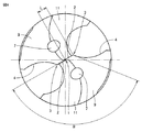
図1〜図3に示すように、本実施形態に係るドリル10は、回転軸1を中心に回転可能なドリル10であって、円弧状の切れ刃4と、シンニング切れ刃2と、らせん状の溝8とを備える。回転軸1に対する溝8の交差角度であるねじれ角はたとえば20°以上40°以下である。当該ねじれ角は25°以上35°以下としてもよい。切れ刃4は、図2に示すように、回転軸1に沿った方向から見たドリル10の先端側に配置される。図1〜図3に示したドリル10では、2つの切れ刃4が形成されている。なお、切れ刃4の数は3以上であってもよい。
<Drill configuration>
As shown in FIGS. 1 to 3, a
シンニング切れ刃2は、ドリル10の先端部に形成される。シンニング切れ刃2は切れ刃4から見て回転軸1側に位置する。シンニング切れ刃2と切れ刃4とは接続部3を介して連なるように形成される。シンニング切れ刃2は、接続部3から回転軸1側に延びるように形成されている。シンニング切れ刃2はたとえば直線状である。異なる観点から言えば、切れ刃4は変曲点としての接続部3を介してシンニング切れ刃2と接続されている。シンニング切れ刃2は、ドリル10の先端側に2つ形成されているが、3つ以上形成されていてもよい。なお、上述のように切れ刃4とシンニング切れ刃2とは連なるように形成されているので、切れ刃4の数とシンニング切れ刃2の数とは同じである。
The thinning
回転軸1に沿った方向から見た、ドリル10の直径Dに対するシンニング切れ刃2の長さLの比率(L/D)は6%以上14%以下である。ここで、シンニング切れ刃2の長さLは、シンニング切れ刃2において回転軸1に最も近接した位置から接続部3までの距離である。ドリル10の直径Dに対するシンニング切れ刃2の長さLの上記比率(L/D)は9%以上11%以下であってもよい。
The ratio (L / D) of the length L of the thinning
図2に示すように、回転軸1に沿った方向から見た、ドリル10の直径Dに対する切れ刃4の曲率半径Rの比率(R/D)は25%以上45%以下である。なお、切れ刃4が円弧状とは異なる形状の部分を含む場合、切れ刃4の曲率半径Rは、切れ刃4のうち円弧状となっている部分における曲率半径とする。ドリル10の直径Dに対する切れ刃4の曲率半径Rの上記比率(R/D)は30%以上35%以下であってもよい。
As shown in FIG. 2, the ratio (R / D) of the radius of curvature R of the
切れ刃4の外周側は、回転軸1から離れる方向である径方向に沿って延びる平坦部5となっている。切れ刃4のすくい面が溝8の内周面に連なっている。また、切れ刃4に隣接する逃げ面6は、ドリル10の先端側の面を構成する。逃げ面6に連なる後面9にはオイルホール7が形成されている。後面9に連なる傾斜面11は、ドリル10の先端側から根元側に向けて傾斜した面である。傾斜面11は溝8の内周面に連なっている。上述したシンニング切れ刃2において回転軸1に最も近接した位置は、上記後面9と傾斜面11との境界線と連なっている。当該境界線は、回転軸1から離れる径方向に向けて直線状に延びている。境界線はドリル10の外周部まで伸びている。
The outer peripheral side of the
回転軸1に沿った方向から見て切れ刃4を含む円弧とシンニング切れ刃2との接続点である接続部3における円弧の接線とシンニング切れ刃2との間の角度αは110°以上150°以下である。当該角度αは120°以上140°以下であってもよい。
The angle α between the tangent of the arc at the connecting
図3に示すように、ドリル10の先端角θは140°以上170°以下とすることができる。先端角θはたとえば160°である。また、ドリル10の直径Dはたとえば7.5mm以下である。ドリル10の直径Dは7mm以下であってもよく、6mm以下であってもよい。ドリル10の直径Dは1mm以上であってもよく、2mm以上であってもよい。
As shown in FIG. 3, the tip angle θ of the
<作用効果>
上述したドリル10において、シンニング切れ刃2の長さLと切れ刃4の曲率半径Rとを上記のように規定することで、3mm以上の長さとなる長い切り屑の発生を抑制できる。すなわち、ドリル10の直径Dに対するシンニング切れ刃2の長さLの比率(L/D)を上述のような数値範囲とすることで、結果的に切れ刃4とシンニング切れ刃2とからなる切れ刃全体におけるシンニング切れ刃2の割合を相対的に小さくしている。この結果、切り屑の分断性を向上させることができる。また、ドリル10の直径Dに対する切れ刃4の曲率半径Rの比率(R/D)を上述のような数値範囲とすることで、結果的に切れ刃4の曲率半径Rを従来より小さくしている。このため、切り屑を変形させて、当該切り屑を小さなカール半径で切断することができる。
<Effect>
In the
また、図2に示す角度αの値を上記のような範囲に設定することで、切れ刃4とシンニング切れ刃2との接続部3で切り屑が分断されず、穴あけ加工の初期から全体としてほぼ一定の長さの切り屑を生成することができる。
Moreover, by setting the value of the angle α shown in FIG. 2 in the above range, the chips are not divided at the
<変形例の構成および作用効果>
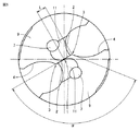
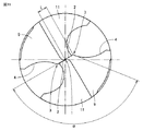
図4〜図11に、本実施形態に係るドリル10の変形例を示す。図4〜図7、図9、図11は、それぞれ図2に対応する。
<Configuration and effect of modification>
4 to 11 show modifications of the
図4に示すドリル10は、基本的には図1〜図3に示したドリル10と同様の構成を備えるが、後面9と傾斜面11との境界線の形状およびオイルホール7の位置が図1〜図3に示したドリル10と異なっている。すなわち、図4に示したドリル10では、後面9と傾斜面11との境界線が曲線状となっている。当該境界線は後面9側に凸の曲線となっている。また、境界線はドリル10の外周部まで伸びている。オイルホール7は、後面9と傾斜面11との境界線と重なるように形成されている。異なる観点から言えば、オイルホール7は、後面9と傾斜面11との両方にまたがるように形成されている。このような構成のドリル10によっても、図1〜図3に示したドリル10と同様の効果を得ることができる。
The
図5に示すドリル10は、基本的には図1〜図3に示したドリル10と同様の構成を備えるが、後面9と傾斜面11との境界線の形状およびオイルホール7の位置が図1〜図3に示したドリル10と異なっている。すなわち、図5に示したドリル10では、後面9と傾斜面11との境界線が円弧状の部分と直線状の部分とにより構成されている。当該境界線は後面9側に凸の曲線となっている。境界線は回転軸1側と反対側の端部が、溝8に繋がっている。すなわち、当該境界線はドリル10の外周部まで伸びていない。オイルホール7は、後面9と傾斜面11との境界線と重なるように形成されている。このような構成のドリル10によっても、図1〜図3に示したドリル10と同様の効果を得ることができる。
The
図6に示すドリル10は、基本的には図1〜図3に示したドリル10と同様の構成を備えるが、オイルホール7の位置および切れ刃4の形状が図1〜図3に示したドリル10と異なっている。すなわち、図6に示したドリル10では、オイルホール7が、後面9と傾斜面11との境界線と重なるように形成されている。また、図6に示したドリル10では、切れ刃4における回転軸1から離れた外周側の部分に平坦部5(図2参照)が形成されていない。つまり、図6に示したドリル10では、円弧状の切れ刃4がドリル10の外周部にまで伸びている。このような構成のドリル10によっても、図1〜図3に示したドリル10と同様の効果を得ることができる。
The
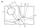
図7および図8に示すドリル10は、基本的には図1〜図3に示したドリル10と同様の構成を備えるが、切れ刃4とシンニング切れ刃2との接続部の形状およびオイルホール7の位置が図1〜図3に示したドリル10と異なっている。すなわち、図7および図8に示したドリル10では、切れ刃4とシンニング切れ刃2との接続部に、切れ刃4とシンニング切れ刃2との間をつなぐ直線部21が形成されている。また、オイルホール7は、後面9と傾斜面11との境界線と重なるように形成されている。このような構成のドリル10によっても、図1〜図3に示したドリル10と同様の効果を得ることができる。
The
なお、このような直線部21が形成されている場合、シンニング切れ刃2の長さLは、以下のように規定する。すなわち、回転軸1に沿った方向から見て切れ刃4を含む円弧とシンニング切れ刃2との仮想の接続点22を考える。そして、シンニング切れ刃2において回転軸1に最も近接した位置から接続点22までの距離をシンニング切れ刃2の長さLとする。
In addition, when such a
図9および図10に示すドリル10は、基本的には図7および図8に示したドリル10と同様の構成を備えるが、切れ刃4とシンニング切れ刃2との接続部の形状が図7および図8に示したドリル10と異なっている。すなわち、図9および図10に示したドリル10では、切れ刃4とシンニング切れ刃2との接続部に、切れ刃4とシンニング切れ刃2との間をつなぐ曲線部23が形成されている。このような構成のドリル10によっても、図7および図8に示したドリル10と同様の効果を得ることができる。
The
なお、このような曲線部23が形成されている場合、シンニング切れ刃2の長さLは、以下のように規定する。すなわち、図7および図8に示したドリル10の場合と同様に、回転軸1に沿った方向から見て切れ刃4を含む円弧とシンニング切れ刃2との仮想の接続点22を考える。そして、シンニング切れ刃2において回転軸1に最も近接した位置から仮想の接続点22までの距離をシンニング切れ刃2の長さLとする。
In addition, when such a
図11に示すドリル10は、基本的には図1〜図3に示したドリル10と同様の構成を備えるが、オイルホールが形成されていない点が図1〜図3に示したドリル10と異なっている。すなわち、図11に示したドリル10では、後面9にオイルホールが形成されていない。このような構成のドリル10によっても、図1〜図3に示したドリル10と同様の効果を得ることができる。
The
<実施例>
本実施形態の効果を確認するため、以下のような実験を行った。
<Example>
In order to confirm the effect of this embodiment, the following experiment was conducted.
1)試料
図1〜図3に示した構成であって、シンニング切れ刃2の長さL、切れ刃4の曲率半径R、切れ刃4とシンニング切れ刃2の間の角度αをそれぞれ変更した18種類のドリルを試料として準備した。各試料とも、ドリルの直径Dは5.5mmとした。また、ドリルの材質はDL1300(DLCコート)とした。ドリルの先端角θは160°とした。ドリルの溝8のねじれ角は25°とした。
1) Sample In the configuration shown in FIGS. 1 to 3, the length L of the thinning
2)実験方法
被削材として、ADC12相当のアルミニウム合金からなる板材を準備した。当該板材の厚みは20mmであった。この被削材に対して、各試料のドリルを用いて設定寿命まで穴あけ加工を行って、このときの長い切り屑の発生割合を計測した。なお、長さ3mm以上の切り屑を長い切り屑として計測した。
2) Experimental method A plate material made of an aluminum alloy equivalent to ADC12 was prepared as a work material. The plate material had a thickness of 20 mm. This work material was drilled to the set life using the drill of each sample, and the generation rate of long chips at this time was measured. Note that chips having a length of 3 mm or more were measured as long chips.
切削条件としては、切削速度Vcを170mm/secとし、送り量fを0.9mm/revとした。また、クーラントの供給条件としてはオイルホールを介しての供給とし、供給圧力は2MPaとした。クーラントはエマルションタイプであって、20倍希釈で用いた。 As cutting conditions, the cutting speed Vc was set to 170 mm / sec, and the feed amount f was set to 0.9 mm / rev. The coolant was supplied through an oil hole, and the supply pressure was 2 MPa. The coolant was an emulsion type and was used at a 20-fold dilution.
3)結果
試料の条件および実験結果を表1に示す。
3) Results Table 1 shows the sample conditions and experimental results.
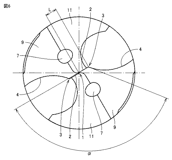
表1においては、シンニング切れ刃長さLの欄には、シンニング切れ刃の長さL(単位:mm)と、ドリルの直径D(単位:mm)に対するシンニング切れ刃の長さLの比率(L/D)とが併記されている。たとえば、試料No.1のシンニング切れ刃長さLの欄における0.275(5%)との表示は、シンニング切れ刃の長さLが0.275mm、上記比率(L/D)が5%であることを示している。 In Table 1, in the column of the thinning cutting edge length L, the length L (unit: mm) of the thinning cutting edge and the ratio of the length L of the thinning cutting edge to the diameter D (unit: mm) of the drill ( L / D). For example, sample No. The display of 0.275 (5%) in the column of 1 thinning cutting edge length L indicates that the length L of the thinning cutting edge is 0.275 mm and the ratio (L / D) is 5%. ing.
また、表1の切れ刃曲率半径Rの欄には、切れ刃4の曲率半径R(単位:mm)と、ドリルの直径D(単位:mm)に対する切れ刃4の曲率半径Rの比率(R/D)とが併記されている。たとえば、試料No.1の切れ刃曲率半径Rの欄におけるR1.9(35%)とは、曲率半径Rが1.9mm、上記比率(R/D)が35%であることを示している。
In the column of the cutting edge curvature radius R in Table 1, the curvature radius R (unit: mm) of the
また、表1の接触角の欄には、図2に示す切れ刃4とシンニング切れ刃2の間の角度αの値が記載されている。そして、3mm以上切り屑発生割合の欄のうち、初期の欄には穴あけ加工の初期(100穴の穴あけ加工を行った時点まで)における、3mm以上の長さの切り屑発生割合を示している。また、設定寿命の欄には、設定寿命とした10000穴の穴あけ加工を行った時点までの、3mm以上の長さの切り屑発生割合を示している。なお、ここでは3mm以上の長さの切り屑発生割合について、5%以下を合格基準とした。
Further, in the contact angle column of Table 1, the value of the angle α between the
表1に示すように、本実施形態の範囲外の試料であるNo.1、6、7、12、13、18については、長い切り屑の発生割合が5%を超えていたり、切り屑の詰まりが発生して評価できなかったり、途中で折損して評価できなかったりした。その一方、本実施形態に対応する試料であるNo.2〜5、8〜11、14〜17については、いずれも長い切り屑の発生割合が5%以下となっており、基準を満たしていた。さらに、試料No.3、4、9、10、15、16については、特に長い切り屑の発生割合が低くなっていた。このように、本実施形態に対応する試料では、長い切り屑の発生を抑制できていることが示された。 As shown in Table 1, No. 1, which is a sample outside the range of the present embodiment. For 1, 6, 7, 12, 13, and 18, the generation rate of long chips exceeds 5%, clogging of chips occurs, and evaluation cannot be performed due to breakage in the middle. did. On the other hand, the sample corresponding to this embodiment is No. About 2-5, 8-11, 14-17, the generation | occurrence | production ratio of the long chip | tip was all 5% or less, and satisfy | filled the reference | standard. Furthermore, sample no. For 3, 4, 9, 10, 15, and 16, the generation ratio of particularly long chips was low. Thus, it was shown that generation of long chips can be suppressed in the sample corresponding to the present embodiment.
今回開示された実施の形態はすべての点で例示であって、制限的なものではないと考えられるべきである。本発明の範囲は上記した実施の形態ではなく特許請求の範囲によって示され、特許請求の範囲と均等の意味、および範囲内でのすべての変更が含まれることが意図される。 The embodiment disclosed this time is to be considered as illustrative in all points and not restrictive. The scope of the present invention is shown not by the above-described embodiment but by the scope of claims, and is intended to include meanings equivalent to the scope of claims and all modifications within the scope.
本発明は、被削材に対する穴あけ加工に特に有利に適用される。 The present invention is particularly advantageously applied to drilling a work material.
1 回転軸
2 シンニング切れ刃
3 接続部
4 切れ刃
5 平坦部
6 逃げ面
7 オイルホール
8 溝
9 後面
10 ドリル
11 傾斜面
21 直線部
22 接続点
23 曲面部
DESCRIPTION OF SYMBOLS 1
Claims (6)
前記回転軸に沿った方向から見た先端側に配置された円弧状の切れ刃と、
前記切れ刃から見て前記回転軸側に位置するとともに前記切れ刃と連なるシンニング切れ刃とを備え、
前記回転軸に沿った方向から見た、前記ドリルの直径に対する前記シンニング切れ刃の長さの比率が6%以上14%以下であり、
前記回転軸に沿った方向から見た、前記ドリルの直径に対する前記切れ刃の曲率半径の比率が25%以上45%以下である、ドリル。 A drill that is rotatable about a rotation axis,
An arcuate cutting edge disposed on the tip side seen from the direction along the rotation axis;
A thinning cutting edge located on the rotary shaft side as viewed from the cutting edge and connected to the cutting edge;
The ratio of the length of the thinning cutting edge to the diameter of the drill as seen from the direction along the rotation axis is 6% or more and 14% or less,
The drill whose ratio of the curvature radius of the cutting edge to the diameter of the drill seen from the direction along the rotation axis is 25% or more and 45% or less.
前記ドリルの直径に対する前記切れ刃の曲率半径の前記比率が30%以上35%以下である、請求項1〜請求項3のいずれか1項に記載のドリル。 The ratio of the length of the thinning cutting edge to the diameter of the drill is 9% or more and 11% or less,
The drill according to any one of claims 1 to 3, wherein the ratio of the radius of curvature of the cutting edge to the diameter of the drill is 30% or more and 35% or less.
Priority Applications (1)
| Application Number | Priority Date | Filing Date | Title |
|---|---|---|---|
| JP2016050698A JP2017164836A (en) | 2016-03-15 | 2016-03-15 | drill |
Applications Claiming Priority (1)
| Application Number | Priority Date | Filing Date | Title |
|---|---|---|---|
| JP2016050698A JP2017164836A (en) | 2016-03-15 | 2016-03-15 | drill |
Related Child Applications (1)
| Application Number | Title | Priority Date | Filing Date |
|---|---|---|---|
| JP2019208821A Division JP2020023051A (en) | 2019-11-19 | 2019-11-19 | Drill |
Publications (1)
| Publication Number | Publication Date |
|---|---|
| JP2017164836A true JP2017164836A (en) | 2017-09-21 |
Family
ID=59909753
Family Applications (1)
| Application Number | Title | Priority Date | Filing Date |
|---|---|---|---|
| JP2016050698A Pending JP2017164836A (en) | 2016-03-15 | 2016-03-15 | drill |
Country Status (1)
| Country | Link |
|---|---|
| JP (1) | JP2017164836A (en) |
Cited By (3)
| Publication number | Priority date | Publication date | Assignee | Title |
|---|---|---|---|---|
| JP2020175465A (en) * | 2019-04-17 | 2020-10-29 | 三菱マテリアル株式会社 | Drill |
| JPWO2021038841A1 (en) * | 2019-08-30 | 2021-09-13 | オーエスジー株式会社 | Drill |
| JP6985569B1 (en) * | 2021-01-27 | 2021-12-22 | 住友電工ハードメタル株式会社 | Drill |
Citations (4)
| Publication number | Priority date | Publication date | Assignee | Title |
|---|---|---|---|---|
| JP2003025125A (en) * | 2001-07-10 | 2003-01-29 | Mitsubishi Materials Corp | Drill |
| JP2011104751A (en) * | 2009-11-20 | 2011-06-02 | Mitsubishi Materials Corp | Drill for spot facing |
| WO2013035166A1 (en) * | 2011-09-06 | 2013-03-14 | オーエスジー株式会社 | Drill |
| WO2013065201A1 (en) * | 2011-11-04 | 2013-05-10 | オーエスジー株式会社 | Drill |
-
2016
- 2016-03-15 JP JP2016050698A patent/JP2017164836A/en active Pending
Patent Citations (4)
| Publication number | Priority date | Publication date | Assignee | Title |
|---|---|---|---|---|
| JP2003025125A (en) * | 2001-07-10 | 2003-01-29 | Mitsubishi Materials Corp | Drill |
| JP2011104751A (en) * | 2009-11-20 | 2011-06-02 | Mitsubishi Materials Corp | Drill for spot facing |
| WO2013035166A1 (en) * | 2011-09-06 | 2013-03-14 | オーエスジー株式会社 | Drill |
| WO2013065201A1 (en) * | 2011-11-04 | 2013-05-10 | オーエスジー株式会社 | Drill |
Cited By (9)
| Publication number | Priority date | Publication date | Assignee | Title |
|---|---|---|---|---|
| JP2020175465A (en) * | 2019-04-17 | 2020-10-29 | 三菱マテリアル株式会社 | Drill |
| JP7375329B2 (en) | 2019-04-17 | 2023-11-08 | 三菱マテリアル株式会社 | Drill |
| US11992887B2 (en) | 2019-04-17 | 2024-05-28 | Mitsubishi Materials Corporation | Drill |
| JPWO2021038841A1 (en) * | 2019-08-30 | 2021-09-13 | オーエスジー株式会社 | Drill |
| JP7001844B2 (en) | 2019-08-30 | 2022-01-20 | オーエスジー株式会社 | Drill |
| US11865626B2 (en) | 2019-08-30 | 2024-01-09 | Osg Corporation | Drill |
| JP6985569B1 (en) * | 2021-01-27 | 2021-12-22 | 住友電工ハードメタル株式会社 | Drill |
| WO2022162774A1 (en) * | 2021-01-27 | 2022-08-04 | 住友電工ハードメタル株式会社 | Drill |
| US12251765B2 (en) | 2021-01-27 | 2025-03-18 | Sumitomo Electric Hardmetal Corp. | Drill |
Similar Documents
| Publication | Publication Date | Title |
|---|---|---|
| JP5927671B2 (en) | Small diameter drill | |
| JP2012511438A (en) | Small drill and method for manufacturing small drill | |
| JP6443914B2 (en) | drill | |
| JP2017024168A (en) | Drill and drill head | |
| WO2010038279A1 (en) | Drill | |
| JP2011189463A (en) | End mill | |
| JP2020023051A (en) | Drill | |
| KR101701023B1 (en) | Drilling tool | |
| WO2016017500A1 (en) | Drill and method of manufacturing cut product using same | |
| JP2019171493A (en) | Drill | |
| JP2009255202A (en) | Drill head for cutting deep hole | |
| JP2017164836A (en) | drill | |
| JP4239414B2 (en) | Drill | |
| JP5549080B2 (en) | drill | |
| JP6383603B2 (en) | drill | |
| JP2018176360A (en) | Rotary cutting hole drilling tool | |
| JP6342662B2 (en) | Drill and method of manufacturing cut product using the same | |
| JP4699526B2 (en) | Drill | |
| JP2006281407A (en) | Machining drill for nonferrous metal | |
| JP2010162643A (en) | Drill and grinding method of the drill | |
| WO2012053090A1 (en) | Three-bladed drill | |
| JP4193360B2 (en) | Drill | |
| WO2010050390A1 (en) | Ball end mill | |
| JP6294095B2 (en) | Drill and method of manufacturing cut product using the same | |
| JP5439821B2 (en) | Drill and grinding method of the drill |
Legal Events
| Date | Code | Title | Description |
|---|---|---|---|
| A625 | Written request for application examination (by other person) |
Free format text: JAPANESE INTERMEDIATE CODE: A625 Effective date: 20180621 |
|
| A131 | Notification of reasons for refusal |
Free format text: JAPANESE INTERMEDIATE CODE: A131 Effective date: 20190312 |
|
| A977 | Report on retrieval |
Free format text: JAPANESE INTERMEDIATE CODE: A971007 Effective date: 20190313 |
|
| A521 | Request for written amendment filed |
Free format text: JAPANESE INTERMEDIATE CODE: A523 Effective date: 20190426 |
|
| A02 | Decision of refusal |
Free format text: JAPANESE INTERMEDIATE CODE: A02 Effective date: 20190820 |
|
| A711 | Notification of change in applicant |
Free format text: JAPANESE INTERMEDIATE CODE: A711 Effective date: 20191118 |
|
| A521 | Request for written amendment filed |
Free format text: JAPANESE INTERMEDIATE CODE: A523 Effective date: 20191202 |