JP2017165155A - Suspended traveling device - Google Patents
Suspended traveling device Download PDFInfo
- Publication number
- JP2017165155A JP2017165155A JP2016050149A JP2016050149A JP2017165155A JP 2017165155 A JP2017165155 A JP 2017165155A JP 2016050149 A JP2016050149 A JP 2016050149A JP 2016050149 A JP2016050149 A JP 2016050149A JP 2017165155 A JP2017165155 A JP 2017165155A
- Authority
- JP
- Japan
- Prior art keywords
- pair
- traveling device
- suspended
- roller
- clamping
- Prior art date
- Legal status (The legal status is an assumption and is not a legal conclusion. Google has not performed a legal analysis and makes no representation as to the accuracy of the status listed.)
- Granted
Links
Images


Landscapes
- Bridges Or Land Bridges (AREA)
- Platform Screen Doors And Railroad Systems (AREA)
Abstract
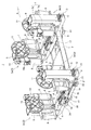
【課題】梁状体からの吊り下げ状態をより安定的に維持させることが可能な吊下型走行装置を提供する。【解決手段】吊下型走行装置1は、梁状体から吊り下がった状態で、梁状体に沿って走行する吊下型走行装置1である。吊下型走行装置1は、梁状体の両側面を挟持する少なくとも一対の挟持部3と、少なくとも一対の挟持部3を相互に連結しているフレーム2と、梁状体28が有する上向き面28bに接地され当該吊下型走行装置1の荷重を支える車輪11と、駆動源(例えばモータ10)を備えている。挟持部3の各々が、鉛直な回転軸周りに回転可能で且つ梁状体28の側面28aを挟持するローラ(駆動ローラ8、従動ローラ9)を備えている。少なくとも1つの挟持部3は、ローラとして、駆動源によって回転駆動されて梁状体28の延在方向である進行方向への推進力を与える駆動ローラ8を備えている。【選択図】図1To provide a suspended traveling device capable of maintaining a suspended state from a beam-like body more stably. A suspended traveling device 1 is a suspended traveling device 1 that travels along a beam-like body while being suspended from the beam-like body. The suspended traveling device 1 includes at least a pair of sandwiching portions 3 that sandwich both side surfaces of the beam-shaped body, a frame 2 that connects at least the pair of sandwiching portions 3 to each other, and an upward surface that the beam-shaped body 28 has. A wheel 11 that is grounded at 28b and supports the load of the suspended traveling device 1 and a drive source (for example, a motor 10) are provided. Each of the sandwiching portions 3 includes a roller (a driving roller 8 and a driven roller 9) that can rotate around a vertical rotation axis and sandwich the side surface 28 a of the beam-like body 28. The at least one clamping unit 3 includes a driving roller 8 that is driven to rotate by a driving source and applies a propulsive force in a traveling direction that is an extending direction of the beam 28 as a roller. [Selection] Figure 1
Description
本発明は、吊下型走行装置に関する。 The present invention relates to a suspended traveling device.
橋梁等が備える梁状体から吊り下がった状態で、梁状体に沿って走行する吊下型走行装置としては、特許文献1に記載されたものがある。
特許文献1の吊下型走行装置は、V字状の傾斜接触面を有する鼓状のローラを回転可能に支持する支持アームを前後二対(合計4つ)備え、二対のローラでI型鋼等の梁状体のフランジを挟持することによって、梁状体から吊り下がった状態となる。
As a suspended traveling device that travels along a beam-like body suspended from a beam-like body included in a bridge or the like, there is one described in
The suspended traveling device of
特許文献1の吊下型走行装置は、上述のようにV字状の傾斜接触面を有する鼓状の4つのローラで梁状体のフランジを挟持することによって梁状体から吊り下がった状態となるため、梁状体からの吊り下げ状態の安定性の面で改善の余地がある。
The suspension type traveling device of
本発明は、上記の課題に鑑みてなされたものであり、梁状体からの吊り下げ状態をより安定的に維持させることが可能な吊下型走行装置を提供するものである。 This invention is made | formed in view of said subject, and provides the suspension type traveling apparatus which can maintain the suspended state from a beam-shaped body more stably.
本発明によれば、梁状体から吊り下がった状態で、前記梁状体に沿って走行する吊下型走行装置であって、前記梁状体の両側面を挟持する少なくとも一対の挟持部と、前記少なくとも一対の挟持部を相互に連結しているフレームと、前記梁状体が有する上向き面に接地され、当該吊下型走行装置の荷重を支える車輪と、駆動源と、を備え、前記挟持部の各々が、鉛直な回転軸周りに回転可能で且つ前記梁状体の側面を挟持するローラを備え、少なくとも1つの前記挟持部は、前記ローラとして、前記駆動源によって回転駆動されて前記梁状体の延在方向である進行方向への推進力を与える駆動ローラを備えている吊下型走行装置が提供される。 According to the present invention, a suspended traveling device that travels along the beam-like body in a state of being suspended from the beam-like body, and includes at least a pair of sandwiching portions that sandwich both side surfaces of the beam-like body. A frame that connects the at least one pair of sandwiching portions to each other, a wheel that is grounded to an upward surface of the beam-like body and supports a load of the suspended traveling device, and a drive source, Each of the sandwiching portions includes a roller that is rotatable about a vertical rotation axis and sandwiches a side surface of the beam-like body, and at least one of the sandwiching portions is rotated and driven by the drive source as the roller. There is provided a suspended traveling device including a driving roller that applies a propulsive force in a traveling direction that is an extending direction of a beam-like body.
本発明によれば、梁状体からの吊り下げ状態をより安定的に維持させることが可能である。 According to the present invention, it is possible to maintain the suspended state from the beam-like body more stably.
以下、本発明の実施形態について、図面を用いて説明する。なお、すべての図面において、同様の構成要素には同一の符号を付し、適宜に説明を省略する。
本実施形態では、各構成要素の位置関係を分かりやすく説明するために、前後左右上下等の方向を規定して説明する場合がある。しかし、これらの方向の規定は便宜的なものであり、本発明を実施する製品の製造時や使用時の方向を限定するものではない。なお、吊下型走行装置の進行方向を前方、進行方向に対する反対方向を後方とする。また、平面視において、吊下型走行装置の進行方向に対して直交する方向を幅方向という。また、幅方向のうち、進行方向を向いた状態で右側となる方向を右方、進行方向を向いた状態で左側となる方向を左方という。
また本発明の各種の構成要素は、個々に独立した存在である必要はなく、一つの構成要素が他の構成要素の一部であること、ある構成要素の一部と他の構成要素の一部とが重複していること、等を許容する。
Hereinafter, embodiments of the present invention will be described with reference to the drawings. In all the drawings, the same components are denoted by the same reference numerals, and description thereof will be omitted as appropriate.
In the present embodiment, in order to explain the positional relationship of each component in an easy-to-understand manner, there are cases where the front / rear / left / right / up / down directions are defined. However, the definition of these directions is for convenience, and does not limit the directions at the time of manufacture and use of the product implementing the present invention. In addition, let the advancing direction of a suspension type traveling apparatus be the front, and let the opposite direction with respect to a advancing direction be back. Further, in a plan view, a direction orthogonal to the traveling direction of the suspended traveling device is referred to as a width direction. In the width direction, the direction on the right side when facing the traveling direction is referred to as the right side, and the direction on the left side when facing the traveling direction is referred to as the left side.
The various constituent elements of the present invention do not have to be independent of each other, one constituent element is a part of another constituent element, a part of one constituent element and one of the other constituent elements. The part is allowed to overlap.
〔第1の実施形態〕
先ず、図1から図7を用いて第1の実施形態を説明する。
本実施形態に係る吊下型走行装置1は、梁状体28(図6)から吊り下がった状態で、梁状体28に沿って走行する吊下型走行装置1である。吊下型走行装置1は、梁状体28の両側面(図6に示される側面28aと反対側の側面28a(不図示))を挟持する少なくとも一対の挟持部3と、少なくとも一対の挟持部3を相互に連結しているフレーム2と、梁状体28が有する上向き面28bに接地され、当該吊下型走行装置1の荷重を支える車輪11と、駆動源(例えばモータ10)と、を備えている。挟持部3の各々が、鉛直な回転軸周りに回転可能で且つ梁状体28の側面28aを挟持するローラ(例えば、駆動ローラ8及び従動ローラ9)を備えている。そして、少なくとも1つの挟持部3は、ローラとして、駆動源によって回転駆動されて梁状体28の延在方向である進行方向(図1の矢印A方向)への推進力を与える駆動ローラ8を備えている。
以下、詳細に説明する。
[First Embodiment]
First, the first embodiment will be described with reference to FIGS.
The suspended traveling
Details will be described below.
フレーム2は、各種の鋼材等の構造材を相互に組み付けることにより、所望の形状に構成されている。本実施形態の場合、フレーム2は、例えば、図2に示すように平面形状が略H字状に形成されており、図3に示すように扁平な形状に形成されている。ただし、フレーム2の形状はこの例に限らない。
The
吊下型走行装置1は、使用状態においては、車輪11及びローラ(駆動ローラ8及び従動ローラ9)によって当該吊下型走行装置1の荷重が支えられて、橋梁等の高架構造物が有する梁状体28から吊り下がった状態となる。この状態で、モータ10の駆動により駆動ローラ8が回転することによって、吊下型走行装置1が梁状体28に沿って走行する。
When the suspended
なお、モータ10は駆動ローラ8を一方向にのみ回転させるものであっても良いし、駆動ローラ8を正/逆回転させることが可能なものであっても良い。前者の場合、吊下型走行装置1は、一方向にのみ走行が可能(前進のみ可能)となり、後者の場合、吊下型走行装置1は、前進と後退とが可能となる。また、モータ10の回転方向が一方向であっても、モータ10から駆動ローラ8に回転を伝達する伝達機構が、駆動ローラ8の回転方向を正回転と逆回転とに切り替え可能な切り替え機構を含んでいる場合には、吊下型走行装置1を前進と後退とが可能な構成とすることができる。
The
梁状体28は、挟持部3によって挟持される一対の側面28aと、車輪11が接地される上向き面28bとを有し、略水平方向に延在するものであれば、特に限定されない。
具体的には、例えば、梁状体28は、橋梁の下面に沿って延在するI桁材であることが挙げられる。
The beam-
Specifically, for example, the
なお、吊下型走行装置1は、フレーム2の下面から下方に突出している複数の(例えば4つの)脚部27を備えており、保管時等にはこれら脚部27が接地した状態で自立可能となっている。
The suspended
より詳細には、吊下型走行装置1は、フレーム2の前部に配置された左右一対の挟持部3(挟持部3a及び挟持部3b)と、フレーム2の後部に配置された左右一対の挟持部3(挟持部3c及び挟持部3d)と、の合計4つの挟持部3を備えている。すなわち、吊下型走行装置1は、フレーム2の左前部に設けられた挟持部3aと、フレーム2の右前部に設けられた挟持部3bと、フレーム2の左後部に設けられた挟持部3cと、フレーム2の右後部に設けられた挟持部3dと、を備えている。
そして、4つの挟持部3の各々が車輪11を備えている。
More specifically, the suspended
Each of the four sandwiching
フレーム2の上面側には、各挟持部3を幅方向にスライド可能にガイドする複数のガイドレール12が設けられている。
すなわち、フレーム2の左前部の上面側には、挟持部3aを左右にガイドするガイドレール12が、水平に且つ左右に延在するように設けられている。同様に、フレーム2の右前部の上面側には、挟持部3bを左右にガイドするガイドレール12が、水平に且つ左右に延在するように設けられている。本実施形態の場合、挟持部3aをガイドするガイドレール12と、挟持部3bをガイドするガイドレール12とは、互いに同一直線上に配置されている。なお、これら2つのガイドレール12は、幅方向において互いに離間しており、これら2つのガイドレール12の間には、後述する間隔調整機構のピニオン15が配置されている。
また、フレーム2の左後部の上面側には挟持部3cを左右にガイドするガイドレール12が、フレーム2の右後部の上面側には挟持部3dを左右にガイドするガイドレール12が、それぞれ水平に且つ左右に延在するように設けられており、これらガイドレール12は互いに同一直線上に配置されている。また、これら2つのガイドレール12は、幅方向において互いに離間しており、これら2つのガイドレール12の間にもピニオン15が配置されている。
On the upper surface side of the
That is, on the upper surface side of the left front portion of the
Further, a
各挟持部3は、フレーム2によって支持されている挟持部ベース4と、挟持部ベース4から起立している支柱部5と、を備えている。
より詳細には、挟持部ベース4は、ガイドレール12によって保持されることによって、ガイドレール12を介してフレーム2により支持されている。挟持部ベース4は、ガイドレール12によって保持されるとともに、左右にスライド可能にガイドレール12によりガイドされている。つまり、挟持部ベース4は、フレーム2に対して相対的に左右に移動可能である。
なお、支柱部5は挟持部ベース4によって支持されているため、挟持部ベース4と一体となって、フレーム2に対して相対的に左右に移動可能である。
また、フレーム2の幅方向における各ガイドレール12の終端位置には、ガイドレール12からの挟持部ベース4の脱落を規制するストッパ13が、ガイドレール12よりも上方に起立した状態に設けられている。
Each clamping
More specifically, the
In addition, since the support |
In addition, a
挟持部3は、進行方向において相互に離間して配置されている一対のローラ(例えば、駆動ローラ8及び従動ローラ9)と、一対のローラをそれぞれ回転可能に保持している保持部7と、を備えている。なお、各ローラの回転軸は鉛直に配置されている。
保持部7は、進行方向において一対のローラ(駆動ローラ8と従動ローラ9)の間に位置する鉛直な回転軸周りにフレーム2に対して首振り回転可能となっている。
The
The holding
より詳細には、保持部7は、フレーム2に対して左右にスライド移動可能な挟持部ベース4及び支柱部5によって軸支されており、挟持部ベース4及び支柱部5に対して、鉛直な回転軸周りに首振り回転可能となっている。
挟持部ベース4及び支柱部5が保持部7を軸支している軸支部6は、進行方向において一対のローラ(駆動ローラ8と従動ローラ9)の間に位置している。
保持部7は、軸支部6を支点として、図2に示す矢印B方向及び矢印C方向に回転可能となっている。
ここで、支柱部5の上端部は、フレーム2の幅方向における中央寄りの方向に向けてオーバーハング状態で突出したオーバーハング部となっており、このオーバーハング部と、挟持部ベース4におけるオーバーハング部の直下の部分とにより、保持部7が軸支されている。
More specifically, the holding
The shaft support portion 6 in which the holding
The holding
Here, the upper end portion of the
より詳細には、保持部7は、一対のローラをそれぞれ回転可能に保持しているローラ保持フレーム7aと、進行方向におけるローラ保持フレーム7aの中央部の上に設けられている車輪保持部7bと、を備えている(図1において挟持部3bの保持部7について付した符号を参照)。
そして、ローラ保持フレーム7aの下端部と車輪保持部7bの上端部とが、挟持部ベース4と支柱部5のオーバーハング部とによって軸支部6において軸支されている。
More specifically, the holding
The lower end portion of the
各挟持部3の保持部7は、ローラ保持フレーム7aの前端部において、一対のローラのうちの一方を軸支しており、当該ローラ保持フレーム7aの後端部において、一対のローラのうちの他方を軸支している。
ここで、各挟持部3は、駆動ローラ8と従動ローラ9とを備えている。すなわち、挟持部3が備える一対のローラのうちの一方が駆動ローラ8である。駆動ローラ8は、上述のように、モータ10により回転駆動されて進行方向への推進力を吊下型走行装置1に与えるローラであり、駆動ローラ8には、モータ10の駆動軸であるモータ軸10aが連結されている。
一方、従動ローラ9は、ローラ保持フレーム7aに対して空回りするようになっており、吊下型走行装置1が走行する際に梁状体28の側面28aから受ける摩擦抵抗によって回転する。
より詳細には、例えば、4つの挟持部3のうち、前側に位置する挟持部3a及び挟持部3bについては、ローラ保持フレーム7aの前端部に従動ローラ9が、ローラ保持フレーム7aの後端部に駆動ローラ8が、それぞれ設けられている。一方、後側に位置する挟持部3c及び挟持部3dについては、ローラ保持フレーム7aの前端部に駆動ローラ8が、ローラ保持フレーム7aの後端部に従動ローラ9が、それぞれ設けられている。
The holding
Here, each clamping
On the other hand, the driven
More specifically, for example, among the four holding
従動ローラ9は、下方に向けてテーパー状に縮径している。すなわち、挟持部3が備える一対のローラのうちの他方が、下方に向けてテーパー状に縮径している。
The driven
駆動ローラ8は、梁状体28の側面28aに対する摩擦力を十分に大きくできるように、当該駆動ローラ8の周面はゴム等により構成されていることが好ましい。
一方、従動ローラ9は、梁状体28の側面28aに対して上下方向に容易に滑動できるように、硬質樹脂により構成されていることが好ましい。
なお、従動ローラ9の周面を構成する材料のヤング率は、駆動ローラ8の周面を構成する材料のヤング率よりも大きいことが好ましい。
It is preferable that the peripheral surface of the
On the other hand, the driven
The Young's modulus of the material constituting the peripheral surface of the driven
なお、各ローラ(駆動ローラ8及び従動ローラ9)を保持しているローラ保持フレーム7aが梁状体28に対して干渉することなく、各ローラが梁状体28の側面28aに対して接触可能となるように、ローラ保持フレーム7aに対する各ローラの配置が設定されている。
In addition, each roller can contact the
車輪11は、各挟持部3の保持部7の車輪保持部7bによって、回転可能に保持されている。すなわち、各挟持部3の保持部7が、個別の車輪11を回転可能に保持している。
各車輪11の回転軸は水平に配置されている。
The
The rotating shaft of each
各車輪11は、各車輪11を保持している車輪保持部7bを基準として、フレーム2の幅方向における中央寄りに配置されている。更に言えば、各挟持部3において、ローラ保持フレーム7aよりも車輪11の方が、フレーム2の幅方向における中央寄りに配置されている。
なお、車輪11を保持している車輪保持部7bは、挟持部ベース4及び支柱部5に対して、鉛直な回転軸周りに首振り回転可能であるため、車輪11は、駆動ローラ8及び従動ローラ9とともに、鉛直な回転軸周りに首振り回転する。
Each
Since the wheel holding portion 7b holding the
本実施形態の場合、4つの挟持部3の各々が備える車輪11が、平面視において正格子状に配置されている(図2、図8(a)参照)。
In the case of the present embodiment, the
図3に示すように、各挟持部3において、駆動ローラ8の上端8aの高さ位置は、車輪11の下端11aよりも上方に位置している。
同様に、各挟持部3において、従動ローラ9のテーパー部分(下方に向けて縮径している部分)の上端9aの高さ位置は、車輪11の下端11aよりも上方に位置している。
また、各挟持部3において、駆動ローラ8の下端8bの高さ位置は、車輪11の下端11aよりも下方に位置している。
同様に、各挟持部3において、従動ローラ9のテーパー部分(下方に向けて縮径している部分)の下端9bの高さ位置は、車輪11の下端11aよりも下方に位置している。
As shown in FIG. 3, the height position of the
Similarly, in each clamping
In each
Similarly, in each clamping
車輪11は、例えば、円板状に形成されている。車輪11の軽量化のため、車輪11における周縁部と中央部とを除く部位には、図1等に示されるように、当該車輪11の板面を貫通する開口が形成されていても良い。
The
また、各挟持部3において、駆動ローラ8を回転駆動させるモータ10は、駆動ローラ8の上方位置において、ローラ保持フレーム7aに載置されている。
In each
吊下型走行装置1は、更に、左右一対の挟持部3の対向間隔を調整するための間隔調整機構を備えている。
すなわち、吊下型走行装置1は、挟持部3aと挟持部3bとの対向間隔を調整するための間隔調整機構と、挟持部3cと挟持部3dとの対向間隔を調整するための間隔調整機構と、を備えている。
間隔調整機構は、平面視において進行方向に対して直交する幅方向に一対の挟持部3をそれぞれ摺動可能にガイドする一対のガイドレール12を備えて構成されている。
The suspended traveling
That is, the suspended traveling
The interval adjusting mechanism includes a pair of
間隔調整機構は、一対の挟持部3のうちの一方の動きを変換して他方に伝達する変換伝達機構を備えている。この変換伝達機構は、一対の挟持部3のうちの一方が他方の側に近づく動きを、他方が一方の側に近づく動きに変換して伝達するとともに、一対の挟持部3のうちの一方が他方から遠ざかる動きを、他方が一方から遠ざかる動きに変換して伝達する。
すなわち、前側に配置された一対の挟持部3a、3bについて説明すると、変換伝達機構は、図2の矢印D方向への挟持部3aの動きを、矢印E方向への動きに変換して挟持部3bに伝達する。また、矢印D方向に対する反対方向(矢印E方向)への挟持部3aの動きを、矢印E方向に対する反対方向(矢印D方向)への動きに変換して挟持部3bに伝達する。同様に、変換伝達機構は、図2の矢印E方向への挟持部3bの動きを、矢印D方向への動きに変換して挟持部3aに伝達する。また、矢印E方向に対する反対方向への挟持部3bの動きを、矢印D方向に対する反対方向への動きに変換して挟持部3aに伝達する。
The interval adjusting mechanism includes a conversion transmission mechanism that converts the movement of one of the pair of holding
That is, the pair of holding
より詳細には、図1及び図2に示すように、変換伝達機構は、挟持部3と一体に設けられたラック14と、ピニオン15と、を備えて構成されている。ピニオン15は、フレーム2によって回転可能に保持されているとともに、ラック14に対して噛み合っており、挟持部3及びラック14が幅方向に移動する際に回転する。
ラック14は、各挟持部3の挟持部ベース4に固定されており、当該ラック14の長手方向が、幅方向に延在している。
各ラック14は、当該ラック14が設けられている挟持部ベース4から、フレーム2の幅方向における中央寄りの方向に向けて延出している。
つまり、挟持部3cのラック14は、挟持部3cの挟持部ベース4から右方に向けて延出しており、挟持部3dのラック14は、挟持部3cの挟持部ベース4から左方に向けて延出している。ここで、挟持部3cのラック14と挟持部3dのラック14とが干渉しないように、例えば、挟持部3cのラック14は挟持部ベース4の前部に固定されている一方で、挟持部3dのラック14は挟持部ベース4の後部に固定されている。挟持部3cのラック14と挟持部3dのラック14とは、互いの歯列が対向するように配置されている。
同様に、挟持部3aのラック14は、挟持部3aの挟持部ベース4から右方に向けて延出しており、挟持部3bのラック14は、挟持部3bの挟持部ベース4から左方に向けて延出している。そして、挟持部3aのラック14と挟持部3bのラック14とが干渉しないように、例えば、挟持部3aのラック14は挟持部ベース4の前部に固定されている一方で、挟持部3bのラック14は挟持部ベース4の後部に固定されている。挟持部3aのラック14と挟持部3bのラック14とは、互いの歯列が対向するように配置されている。
More specifically, as shown in FIGS. 1 and 2, the conversion transmission mechanism is configured to include a
The
Each
That is, the
Similarly, the
ピニオン15は、一対のラック14に対してそれぞれ噛み合っている。
すなわち、挟持部3aと挟持部3bとの対向間隔を調整するための間隔調整機構のラック14は、挟持部3aに設けられたラック14と、挟持部3bに設けられたラック14と、の双方に対して噛み合っている。
また、挟持部3cと挟持部3dとの対向間隔を調整するための間隔調整機構のラック14は、挟持部3cに設けられたラック14と、挟持部3dに設けられたラック14と、の双方に対して噛み合っている。
各ピニオン15は、例えば、フレーム2の幅方向における中央部に配置されており、鉛直な回転軸周りに回転可能なように、フレーム2によって保持されている。
The
That is, the
Further, the
Each
間隔調整機構が上記のように構成されていることによって、左右一対の挟持部3の動作が連動(幅方向において、互いに反対方向に移動)するようになっている。
すなわち、挟持部3dがガイドレール12に沿って右方に移動する際には、挟持部3dに設けられたラック14も右方に移動し、このラック14と噛み合っているピニオン15が平面視において反時計回りに回転する。これにより、挟持部3cに設けられたラック14が左方に移動し、従って、挟持部3cがガイドレール12に沿って左方に移動する。
一方、挟持部3dがガイドレール12に沿って左方に移動する際には、挟持部3dに設けられたラック14も左方に移動し、このラック14と噛み合っているピニオン15が平面視において時計回りに回転する。これにより、挟持部3cに設けられたラック14が右方に移動し、従って、挟持部3cがガイドレール12に沿って右方に移動する。
挟持部3aと挟持部3bについても、挟持部3cと挟持部3dの関係と同様に、互いに連動する。
Since the interval adjusting mechanism is configured as described above, the operations of the pair of left and right sandwiching
That is, when the clamping
On the other hand, when the clamping
The sandwiching
なお、間隔調整機構は、ピニオン15に対する一対のラック14の噛み合い状態を維持させるために、一対のラック14が進行方向において互いに離間してしまうことを規制する離間規制機構を備えている。
この離間規制機構は、例えば、連結バー16と、連結バー16の両端にそれぞれ設けられた一対のガイドローラ17と、を備えて構成されている。
連結バー16は、例えば、進行方向に延在する板状部材であり、間隔調整機構の一対のラック14の上面間に架け渡されており、且つ、当該連結バー16の長手方向における中央部に、間隔調整機構のピニオン15の回転軸の上端が設けられている。
一対のガイドローラ17の各々は、鉛直な回転軸周りに回転可能に、連結バー16の端部と、フレーム2との間において、それぞれ軸支されている。
離間規制機構の一対のガイドローラ17のうち、前側のガイドローラ17の周面は、間隔調整機構の一対のラック14のうち前側のラック14の前面に接しており、後側のガイドローラ17の周面は、間隔調整機構の一対のラック14のうち後側のラック14の後面に接している。
これにより、離間規制機構によって、間隔調整機構の一対のラック14が進行方向において互いに離間してしまうことが規制され、その結果、ピニオン15に対する一対のラック14の噛み合い状態が維持されるようになっている。
なお、ラック14が左右に移動する際、当該ラック14に当接しているガイドローラ17が定位置で回転する。
The interval adjusting mechanism includes a separation regulating mechanism that regulates the pair of
The separation regulating mechanism includes, for example, a
The connecting
Each of the pair of
Of the pair of
Accordingly, the separation regulating mechanism restricts the pair of
When the
また、間隔調整機構は、左右一対の挟持部3を相互に近づく方向に弾性的に付勢可能な付勢部を備えている。
本実施形態の場合、付勢部は、シリンダ19とピストンロッド20とを有する伸縮式のシリンダダンパ18である。シリンダダンパ18は、ピストンロッド20がシリンダ19に対してより深く入り込む際に抵抗を与えるように構成されている。
そして、間隔調整機構は、シリンダダンパ18と連結されているとともにシリンダダンパ18を縮める方向及びその反対方向に揺動可能なレバー21と、レバー21によりシリンダダンパ18を縮めた状態でレバー21が係止可能なレバー係止部26と、を更に備えている。
The interval adjusting mechanism includes a biasing portion that can elastically bias the pair of left and right sandwiching
In the case of this embodiment, the urging portion is an
The interval adjusting mechanism is connected to the
図5に示すように、レバー21の一端部は、レバー軸支部22においてフレーム2に対して軸支されており、レバー21は、レバー軸支部22を支点として揺動可能となっている。レバー21の回転軸(揺動軸)は、水平方向且つ前後方向に延在している。
シリンダダンパ18の一端部は、ダンパ軸支部23においてレバー21に対して軸支されている。ダンパ軸支部23は、レバー21の長手方向における中央部よりもレバー軸支部22の近くに位置していることが好ましい。
As shown in FIG. 5, one end portion of the
One end of the
ここで、前後二対の挟持部3のうち、前側に配置されている挟持部3a、3bの間隔を調整するための間隔調整機構に関して説明すると、一対のラック14のうち、前側に位置するラック14の先端部には、連結部24が固定されている。連結部24は、例えば、上下に長尺な板状部材であり、ラック14の先端部から下方に垂下している。
一方、前後二対の挟持部3のうち、後側に配置されている挟持部3a、3bの間隔を調整するための間隔調整機構に関して説明すると、一対のラック14のうち後側に位置するラック14の先端部に連結部24が固定されている。
Here, of the two pairs of front and
On the other hand, the distance adjusting mechanism for adjusting the distance between the holding
シリンダダンパ18の他端部は、ダンパ軸支部25において、連結部24の下端部に対して軸支されている。
ダンパ軸支部23及びダンパ軸支部25におけるシリンダダンパ18の回転軸は、レバー軸支部22におけるレバー21の回転軸に対して平行となっている。
また、レバー係止部26は、レバー21の軌跡が形成する円に対して直交するようにフレーム2から突出して設けられており、レバー21は、レバー係止部26に対して係脱自在となっている。
The other end portion of the
The rotation axis of the
Further, the
図5はレバー21をレバー係止部26から外した状態の正面図である。
一方、図4はレバー21をレバー係止部26に対して係止した状態の正面図である。
FIG. 5 is a front view of the state in which the
On the other hand, FIG. 4 is a front view of a state where the
なお、吊下型走行装置1は、例えば、平面視において、前後対称且つ左右対称に形成されていることが好ましい。
フレーム2には、吊下型走行装置1の用途に応じた各種の搭載物29(図3)を搭載することができる。一例として、吊下型走行装置1は、橋梁の劣化診断に用いることができ、その場合、搭載物29には、カメラ等が含まれる。
搭載物29は、図3に示すように、フレーム2の下面側に配置されても良いし、フレーム2の上面側に配置されても良い。または、搭載物29は、フレーム2よりも側方に突出する状態で、フレーム2によって保持されても良い。
The suspended traveling
Various mounts 29 (FIG. 3) corresponding to the application of the suspended traveling
As shown in FIG. 3, the mounted
吊下型走行装置1は、各挟持部3のモータ10の動作制御を行うための図示しない制御部を備えている。各挟持部3のモータ10が制御部によって同期制御されることによって、各挟持部3の駆動ローラ8が同期して回転し、吊下型走行装置1が前進することができる。
なお、制御部は、例えば、搭載物29とともにフレーム2に搭載することができる。
The suspended traveling
The control unit can be mounted on the
次に、動作を説明する。 Next, the operation will be described.
図6に示すように、吊下型走行装置1は、梁状体28から吊り下がった状態で、梁状体28に沿って走行することができる。梁状体28は、例えば、橋梁の下面側に設けられたI桁材であり、下端部281がフランジ状に形成されている。吊下型走行装置1は、このフランジ状の下端部281の両方の側面28aを左右の挟持部3のローラ(駆動ローラ8及び従動ローラ9)によって挟持し、且つ、フランジ状の下端部281の上面である上向き面28bに車輪11が接地されることによって、梁状体28から吊り下がった状態となる。
As shown in FIG. 6, the suspended traveling
吊下型走行装置1が梁状体28から吊り下がった状態とするためには、先ず、各間隔調整機構のレバー21をレバー係止部26から外した状態(図5参照)で、各車輪11及び各ローラ(駆動ローラ8、従動ローラ9)を、それぞれ対応する側面28a及び上向き面28bに対して位置合わせする。
なお、この状態では、左右の車輪11の対向間隔が、フランジ状の下端部281の左右幅よりも広くなるように、吊下型走行装置1が構成されているものとする。
In order to make the suspended traveling
In this state, it is assumed that the suspended traveling
次に、各間隔調整機構のレバー21をレバー係止部26に対して係止させることによって、左右の車輪11の対向間隔を、フランジ状の下端部281の左右幅よりも狭める。
これにより、左右の挟持部3のローラ(駆動ローラ8及び従動ローラ9)によって、フランジ状の下端部281の左右の側面28aが挟持されるとともに、フランジ状の下端部281の上面である上向き面28bに各車輪11が接地され、吊下型走行装置1が梁状体28から吊り下がった状態となる。
ここで、レバー21をレバー係止部26に対して係止させる際に、レバー21によってシリンダダンパ18が圧縮されて縮む。このため、シリンダダンパ18の付勢力によって、各駆動ローラ8及び各従動ローラ9が梁状体28の側面28aに対して密着する。
Next, the opposing distance between the left and
As a result, the left and right side surfaces 28a of the flange-like
Here, when the
ここで、当該梁状体28の長手方向において間欠的に、垂直補剛材30や上面構造物31が設けられている。
垂直補剛材30は、上向き面28bから起立した板状部材であり、車輪11は垂直補剛材30を通り抜けることができない。このため、車輪11は、上向き面28bにおいて、垂直補剛材30よりも幅方向における端部側の部分(図6に示される余白部28d)に載置されるものとする。
また、上面構造物31は、上向き面28bに沿って配置された板状部材であり、ボルト等によって、フランジ状の下端部281に固定されている。車輪11は、上面構造物31を乗り越えることは可能であるが、上面構造物31を避けて走行することが好ましい。このため、車輪11は、上向き面28bにおいて、上面構造物31よりも幅方向における端部側の部分(図6に示される余白部28c)に載置されることが好ましい。
Here, the
The
The
吊下型走行装置1が梁状体28から吊り下がった状態で、各挟持部3のモータ10が駆動し、各駆動ローラ8が回転することによって、吊下型走行装置1が梁状体28に沿って前進する。すなわち、進行方向右側の2つの駆動ローラ8は、それぞれ平面視において反時計回りに回転し、進行方向左側の2つの駆動ローラ8は、それぞれ平面視において時計回りに回転することにより、吊下型走行装置1が前進することができる。
この際に、各挟持部3の車輪11が上向き面28bに接地されていて、それぞれ吊下型走行装置1の荷重を支えるため、梁状体28からの吊下型走行装置1の吊り下げ状態を安定的に維持することが可能である。
なお、4つの車輪11によって支えられる荷重は、吊下型走行装置1及び搭載物29の全荷重のうち、駆動ローラ8及び従動ローラ9と側面28aとの摩擦抵抗を差し引いた残りの荷重であり、この荷重を4つの車輪11で分担して支えることとなる。
In a state where the suspended traveling
At this time, since the
The load supported by the four
ここで、梁状体28のフランジ状の下端部281の幅寸法は、必ずしも一定ではなく、部分的に広がったり狭まったりする場合がある。
このような事情に対し、本実施形態では、保持部7は、進行方向において一対のローラ(駆動ローラ8、従動ローラ9)の間に位置する鉛直な回転軸周りにフレーム2に対して回転可能となっている。このため、下端部281の幅の変化に応じてフレーム2が首振り回転することにより、各ローラが常に側面28aに対して密着した状態を維持することができる。
Here, the width dimension of the flange-like
In this embodiment, the holding
更に、吊下型走行装置1は、一対の挟持部3の対向間隔を調整するための間隔調整機構を有するため、下端部281の幅の変化に応じて、一対の挟持部3の対向間隔が自動的に調整される。よって、各ローラが常に側面28aに対して密着した状態を維持することができる。
特に、間隔調整機構は、一対の挟持部3を相互に離間する方向に弾性的に付勢可能な付勢部であるシリンダダンパ18を備えている。よって、シリンダダンパ18による付勢によって、常に駆動ローラ8及び従動ローラ9が側面28aに対して密着した状態を維持することができる。
Further, since the suspended traveling
In particular, the distance adjusting mechanism includes a
また、上向き面28bは、必ずしも平坦では無く、部分的に隆起している場合(ゴミが載っている場合も含まれる)がある。また、車輪11が上記の上面構造物31に乗り上げて走行する必要がある場合もあり得る。すなわち、車輪11が上向き面28bの段差や隆起に乗り上げて走行する場合がある。
ここで、挟持部3が備える前後一対のローラのうちの片方が、下方に向けてテーパー状に縮径している従動ローラ9であるため、当該従動ローラ9と側面28aとの摩擦抵抗は、従動ローラ9が円筒状の場合よりも低減されている。
このため、車輪11が段差や隆起に乗り上げたり、段差や隆起から降りる際に、従動ローラ9と側面28aとの間に生じる上下方向の摩擦抵抗を低減できる。よって、車輪11が段差や隆起に乗り上げたり段差や隆起から降りる際の動作をスムーズにすることができる。
Further, the
Here, since one of the pair of front and rear rollers included in the sandwiching
For this reason, when the
以上のような実施形態によれば、吊下型走行装置1は、梁状体28の両方の側面28aを挟持する少なくとも一対の挟持部3と、梁状体28が有する上向き面28bに接地されて当該吊下型走行装置1の荷重を支える車輪11とを備え、挟持部3の各々が、鉛直な回転軸周りに回転可能で且つ梁状体28の側面28aを挟持するローラを備えている。
よって、梁状体28からの吊下型走行装置1の吊り下げ状態を安定的に維持させることが可能である。
According to the embodiment as described above, the suspended traveling
Therefore, it is possible to stably maintain the suspended state of the suspended traveling
〔第2の実施形態〕
次に、図7を用いて第2の実施形態を説明する。
本実施形態に係る吊下型走行装置1は、左右一対の吊下型走行部50と、これら吊下型走行部50を相互に連結している連結部材32と、を備えている。
各吊下型走行部50は、上記の第1の実施形態における吊下型走行装置1と同様に構成されており、それぞれ対応する梁状体28から吊り下がった状態で、対応する梁状体28に沿って走行可能である。
本実施形態の場合も、各吊下型走行部50の各モータ10を同期制御することにより、左右の吊下型走行部50を、互いに足並みを揃えて走行させることができる。
本実施形態の場合、連結部材32に搭載物29を搭載することができるが、必要に応じて、各吊下型走行部50のフレーム2にも搭載物29を搭載しても良い。
[Second Embodiment]
Next, a second embodiment will be described with reference to FIG.
The suspended traveling
Each suspension
Also in this embodiment, by controlling each
In the case of the present embodiment, the
以上、図面を参照して各実施形態を説明したが、これらは本発明の例示であり、上記以外の様々な構成を採用することもできる。 As mentioned above, although each embodiment was described with reference to drawings, these are illustrations of the present invention, and various configurations other than the above can also be adopted.
例えば、上記の第1の実施形態では、各挟持部3が駆動ローラ8を備える例を説明したが、少なくとも1つ以上の挟持部3が駆動ローラ8を備えていることにより、吊下型走行装置1が走行することが可能となる。
For example, in the above-described first embodiment, the example in which each
例えば、上記の第1の実施形態では、4つの挟持部3の各々が備える車輪11が、平面視において正格子状に配置されている例(図2、図8(a))を説明したが、本発明は、この例に限らない。
例えば、図8(b)に示すように、4つの挟持部3の各々が備える車輪11が、平面視において千鳥格子状に配置されていても良い。
For example, in the first embodiment described above, an example (FIGS. 2 and 8A) in which the
For example, as shown in FIG. 8B, the
なお、図8(b)のように車輪11が千鳥格子状に配置されている場合、左右一対の挟持部3に対して設けられた一対のガイドレール12は、前後方向において互いにズレた位置に配置することができる。そして、ピニオン15を十分に大径に形成することによって、左右一対の挟持部3に対してそれぞれ設けられた一対のラック14に対してそれぞれピニオン15を噛み合わせることができる。或いは、一対のラック14の間に、3つ以上の奇数個のピニオン15を配置し、一方のラック14から他方のラック14に対して、3つ以上のピニオン15を順次に介して回転力を伝達するようにしても良い。
或いは、図8(b)のように車輪11が千鳥格子状に配置されている場合に、左右一対の挟持部3に対して設けられた一対のガイドレール12を、平面視において左右一対の挟持部3の軸支部6を結ぶ直線上に配置しても良い。この場合、左右一対の挟持部3が備える4つのローラ(2つずつの駆動ローラ8及び従動ローラ9)が、平面視において平行四辺形の各頂点に配置される。
When the
Alternatively, when the
また、各挟持部3が前後一対のローラ(例えば駆動ローラ8及び従動ローラ9)を備えている例を説明したが、各挟持部3は、1つ以上のローラを備えていれば良い。
また、各挟持部3が車輪11を備えている例を説明したが、複数の挟持部3の中には、車輪11を備えていない挟持部3が含まれていても良い。
Moreover, although each clamping
Moreover, although the example in which each clamping
また、挟持部3が1つずつの車輪11を備えている例を説明したが、挟持部3が前後に離間して2つ以上の車輪11を備えていても良い。例えば、挟持部3が1つのローラを備えている場合に、このローラの前方と後方とにそれぞれ1つずつの車輪11が配置されていることによっても、ローラと車輪11との干渉を回避しつつ、これら車輪11によって好適に吊下型走行装置1の荷重を支えることができる。
Moreover, although the example in which the
本実施形態は以下の技術思想を包含する。
(1)梁状体から吊り下がった状態で、前記梁状体に沿って走行する吊下型走行装置であって、前記梁状体の両側面を挟持する少なくとも一対の挟持部と、前記少なくとも一対の挟持部を相互に連結しているフレームと、前記梁状体が有する上向き面に接地され、当該吊下型走行装置の荷重を支える車輪と、駆動源と、を備え、前記挟持部の各々が、鉛直な回転軸周りに回転可能で且つ前記梁状体の側面を挟持するローラを備え、少なくとも1つの前記挟持部は、前記ローラとして、前記駆動源によって回転駆動されて前記梁状体の延在方向である進行方向への推進力を与える駆動ローラを備えている吊下型走行装置。
(2)前記挟持部は、前記進行方向において相互に離間して配置されている一対の前記ローラと、前記一対のローラをそれぞれ回転可能に保持している保持部と、を備え、前記保持部は、前記進行方向において前記一対のローラの間に位置する鉛直な回転軸周りに前記フレームに対して回転可能となっている(1)に記載の吊下型走行装置。
(3)前記挟持部が備える前記一対のローラのうちの一方が前記駆動ローラである(2)に記載の吊下型走行装置。
(4)前記挟持部が備える前記一対のローラのうちの他方が、下方に向けてテーパー状に縮径している(3)に記載の吊下型走行装置。
(5)各挟持部の前記保持部が、個別の前記車輪を回転可能に保持している(1)から(4)のいずれか一項に記載の吊下型走行装置。
(6)前記一対の挟持部の対向間隔を調整するための間隔調整機構を備え、前記間隔調整機構は、平面視において前記進行方向に対して直交する幅方向に前記一対の挟持部をそれぞれ摺動可能にガイドする一対のガイドレールを備えて構成されている(1)から(5)のいずれか一項に記載の吊下型走行装置。
(7)前記間隔調整機構は、前記一対の挟持部のうちの一方の動きを変換して他方に伝達する変換伝達機構を備え、前記変換伝達機構は、前記一対の挟持部のうちの一方が他方の側に近づく動きを、他方が一方の側に近づく動きに変換して伝達するとともに、前記一対の挟持部のうちの一方が他方から遠ざかる動きを、他方が一方から遠ざかる動きに変換して伝達する(6)に記載の吊下型走行装置。
(8)前記間隔調整機構は、前記一対の挟持部を相互に近づく方向に弾性的に付勢可能な付勢部を備えている(6)又は(7)に記載の吊下型走行装置。
(9)前記付勢部は、シリンダとピストンロッドとを有する伸縮式のシリンダダンパであり、前記間隔調整機構は、前記シリンダダンパと連結されているとともに前記シリンダダンパを縮める方向及びその反対方向に揺動可能なレバーと、前記レバーにより前記シリンダダンパを縮めた状態で前記レバーが係止可能なレバー係止部と、を更に備えている(8)に記載の吊下型走行装置。
(10)前記フレームの前部に配置された一対の前記挟持部と、前記フレームの後部に配置された一対の前記挟持部と、の合計4つの前記挟持部を備え、4つの前記挟持部の各々が前記車輪を備えている(1)から(9)のいずれか一項に記載の吊下型走行装置。
(11)4つの前記挟持部の各々が備える前記車輪が、平面視において正格子状に配置されている(10)に記載の吊下型走行装置。
(12)4つの前記挟持部の各々が備える前記車輪が、平面視において千鳥格子状に配置されている(10)に記載の吊下型走行装置。
This embodiment includes the following technical ideas.
(1) A suspended traveling device that travels along the beam-like body while being suspended from the beam-like body, and includes at least a pair of sandwiching portions that sandwich both side surfaces of the beam-like body; A frame that connects the pair of sandwiching parts to each other; a wheel that is grounded to an upward surface of the beam-like body and supports a load of the suspended traveling device; and a drive source. Each includes a roller that is rotatable about a vertical rotation axis and sandwiches a side surface of the beam-like body, and at least one of the sandwiching portions is rotated and driven by the drive source as the roller. A suspended traveling device provided with a drive roller that applies a propulsive force in the traveling direction, which is the extending direction of.
(2) The holding portion includes a pair of the rollers that are spaced apart from each other in the traveling direction, and a holding portion that rotatably holds the pair of rollers, and the holding portion. Is a suspended traveling device according to (1), which is rotatable with respect to the frame around a vertical rotation axis located between the pair of rollers in the traveling direction.
(3) The suspended traveling device according to (2), wherein one of the pair of rollers included in the clamping unit is the drive roller.
(4) The suspended traveling device according to (3), in which the other of the pair of rollers included in the clamping unit has a tapered diameter that decreases downward.
(5) The suspension type traveling device according to any one of (1) to (4), wherein the holding portion of each clamping portion holds the individual wheels rotatably.
(6) An interval adjusting mechanism for adjusting an opposing interval between the pair of holding portions is provided, and the interval adjusting mechanism slides the pair of holding portions in a width direction orthogonal to the traveling direction in a plan view. The suspended traveling device according to any one of (1) to (5), comprising a pair of guide rails that are movably guided.
(7) The interval adjusting mechanism includes a conversion transmission mechanism that converts a movement of one of the pair of holding portions and transmits the converted movement to the other, and the conversion transmission mechanism is configured so that one of the pair of holding portions is The movement of approaching the other side is converted into the movement of the other approaching one side and transmitted, and the movement of one of the pair of clamping parts away from the other is converted into the movement of the other away from the other. The suspended traveling device according to (6) for transmission.
(8) The suspension type traveling device according to (6) or (7), wherein the gap adjusting mechanism includes a biasing portion that can elastically bias the pair of sandwiching portions in a direction approaching each other.
(9) The urging portion is a telescopic cylinder damper having a cylinder and a piston rod, and the distance adjusting mechanism is connected to the cylinder damper and is retracted in the opposite direction. The suspended traveling device according to (8), further comprising: a swingable lever; and a lever locking portion that can be locked by the lever when the cylinder damper is contracted by the lever.
(10) A total of four sandwiching portions including a pair of the sandwiching portions disposed at the front portion of the frame and a pair of the sandwiching portions disposed at the rear portion of the frame. The suspension type traveling device according to any one of (1) to (9), wherein each of the suspension type traveling devices includes the wheel.
(11) The suspended traveling device according to (10), in which the wheels included in each of the four sandwiching portions are arranged in a regular lattice shape in a plan view.
(12) The suspended traveling device according to (10), in which the wheels included in each of the four clamping portions are arranged in a staggered pattern in a plan view.
1 吊下型走行装置
2 フレーム
3 挟持部
4 挟持部ベース
5 支柱部
6 軸支部
7 保持部
7a ローラ保持フレーム
7b 車輪保持部
8 駆動ローラ(ローラ)
8a 上端
8b 下端
9 従動ローラ(ローラ)
9a 上端
9b 下端
10 モータ(駆動源)
10a モータ軸
11 車輪
11a 下端
12 ガイドレール
13 ストッパ
14 ラック
15 ピニオン
16 連結バー
17 ガイドローラ
18 シリンダダンパ
19 シリンダ
20 ピストンロッド
21 レバー
22 レバー軸支部
23、25 ダンパ軸支部
24 連結部
26 レバー係止部
27 脚部
28 梁状体
28a 側面
28b 上向き面
28c 余白部
28d 余白部
29 搭載物
30 垂直補剛材
31 上面構造物
32 連結部材
DESCRIPTION OF
8a
Claims (12)
前記梁状体の両側面を挟持する少なくとも一対の挟持部と、
前記少なくとも一対の挟持部を相互に連結しているフレームと、
前記梁状体が有する上向き面に接地され、当該吊下型走行装置の荷重を支える車輪と、
駆動源と、
を備え、
前記挟持部の各々が、鉛直な回転軸周りに回転可能で且つ前記梁状体の側面を挟持するローラを備え、
少なくとも1つの前記挟持部は、前記ローラとして、前記駆動源によって回転駆動されて前記梁状体の延在方向である進行方向への推進力を与える駆動ローラを備えている吊下型走行装置。 A suspended traveling device that travels along the beam in a state suspended from the beam,
At least a pair of sandwiching portions sandwiching both side surfaces of the beam-shaped body;
A frame interconnecting the at least one pair of sandwiching portions;
Wheels that are grounded on the upward surface of the beam-like body and support the load of the suspended traveling device;
A driving source;
With
Each of the clamping parts includes a roller that is rotatable around a vertical rotation axis and clamps a side surface of the beam-like body,
At least one of the sandwiching portions is a suspended traveling device that includes a driving roller that is rotationally driven by the driving source and applies a propulsive force in a traveling direction that is an extending direction of the beam-like body as the roller.
前記進行方向において相互に離間して配置されている一対の前記ローラと、
前記一対のローラをそれぞれ回転可能に保持している保持部と、
を備え、
前記保持部は、前記進行方向において前記一対のローラの間に位置する鉛直な回転軸周りに前記フレームに対して回転可能となっている請求項1に記載の吊下型走行装置。 The clamping part is
A pair of the rollers disposed apart from each other in the traveling direction; and
A holding part that holds the pair of rollers rotatably;
With
2. The suspended traveling device according to claim 1, wherein the holding portion is rotatable with respect to the frame around a vertical rotation axis positioned between the pair of rollers in the traveling direction.
前記間隔調整機構は、平面視において前記進行方向に対して直交する幅方向に前記一対の挟持部をそれぞれ摺動可能にガイドする一対のガイドレールを備えて構成されている請求項1から5のいずれか一項に記載の吊下型走行装置。 An interval adjusting mechanism for adjusting the facing interval between the pair of sandwiching portions;
The said space | interval adjustment mechanism is comprised with a pair of guide rail which each guides the said pair of clamping part so that sliding is possible in the width direction orthogonal to the said advancing direction in planar view. The suspended traveling device according to any one of the above.
前記一対の挟持部のうちの一方の動きを変換して他方に伝達する変換伝達機構を備え、
前記変換伝達機構は、前記一対の挟持部のうちの一方が他方の側に近づく動きを、他方が一方の側に近づく動きに変換して伝達するとともに、前記一対の挟持部のうちの一方が他方から遠ざかる動きを、他方が一方から遠ざかる動きに変換して伝達する請求項6に記載の吊下型走行装置。 The interval adjusting mechanism is
A conversion transmission mechanism that converts one movement of the pair of clamping parts and transmits the movement to the other;
The conversion transmission mechanism converts and transmits a movement in which one of the pair of clamping parts approaches the other side into a movement in which the other approaches one side, and one of the pair of clamping parts The suspended traveling device according to claim 6, wherein a movement away from the other is converted into a movement away from the other and transmitted.
前記間隔調整機構は、
前記シリンダダンパと連結されているとともに前記シリンダダンパを縮める方向及びその反対方向に揺動可能なレバーと、
前記レバーにより前記シリンダダンパを縮めた状態で前記レバーが係止可能なレバー係止部と、
を更に備えている請求項8に記載の吊下型走行装置。 The urging portion is a telescopic cylinder damper having a cylinder and a piston rod,
The interval adjusting mechanism is
A lever connected to the cylinder damper and capable of swinging in the direction of contracting the cylinder damper and in the opposite direction;
A lever locking portion that can lock the lever in a state in which the cylinder damper is contracted by the lever;
The suspended traveling device according to claim 8, further comprising:
4つの前記挟持部の各々が前記車輪を備えている請求項1から9のいずれか一項に記載の吊下型走行装置。 A total of four clamping parts, including a pair of clamping parts arranged at the front part of the frame and a pair of clamping parts arranged at the rear part of the frame;
The suspended type traveling device according to any one of claims 1 to 9, wherein each of the four holding portions includes the wheel.
Priority Applications (1)
| Application Number | Priority Date | Filing Date | Title |
|---|---|---|---|
| JP2016050149A JP6510997B2 (en) | 2016-03-14 | 2016-03-14 | Suspension type traveling device |
Applications Claiming Priority (1)
| Application Number | Priority Date | Filing Date | Title |
|---|---|---|---|
| JP2016050149A JP6510997B2 (en) | 2016-03-14 | 2016-03-14 | Suspension type traveling device |
Publications (2)
| Publication Number | Publication Date |
|---|---|
| JP2017165155A true JP2017165155A (en) | 2017-09-21 |
| JP6510997B2 JP6510997B2 (en) | 2019-05-08 |
Family
ID=59909778
Family Applications (1)
| Application Number | Title | Priority Date | Filing Date |
|---|---|---|---|
| JP2016050149A Expired - Fee Related JP6510997B2 (en) | 2016-03-14 | 2016-03-14 | Suspension type traveling device |
Country Status (1)
| Country | Link |
|---|---|
| JP (1) | JP6510997B2 (en) |
Cited By (2)
| Publication number | Priority date | Publication date | Assignee | Title |
|---|---|---|---|---|
| CN114214932A (en) * | 2021-12-21 | 2022-03-22 | 武汉市市政工程机械化施工有限公司 | Bridge detection device with mobile structure |
| CN115791968A (en) * | 2022-12-06 | 2023-03-14 | 六安市辉正检验检测有限公司 | Nondestructive testing instrument for steel structure detection |
Citations (6)
| Publication number | Priority date | Publication date | Assignee | Title |
|---|---|---|---|---|
| JPH0813421A (en) * | 1994-06-22 | 1996-01-16 | Railway Technical Res Inst | Bridge operation car |
| JPH11323857A (en) * | 1998-05-14 | 1999-11-26 | Shinko Electric Co Ltd | Turning posture correction device for work vehicle in tunnel |
| JP2001048005A (en) * | 1999-08-04 | 2001-02-20 | Hitachi Plant Eng & Constr Co Ltd | Transport equipment |
| JP2002013107A (en) * | 2000-06-29 | 2002-01-18 | Kayaba Ind Co Ltd | Bridge inspection car |
| JP2003119721A (en) * | 2001-10-18 | 2003-04-23 | Kawada Kogyo Kk | Work trolley for elevated structures |
| WO2015011860A1 (en) * | 2013-07-23 | 2015-01-29 | 村田機械株式会社 | Moving vehicle and method whereby moving vehicle is moved |
-
2016
- 2016-03-14 JP JP2016050149A patent/JP6510997B2/en not_active Expired - Fee Related
Patent Citations (6)
| Publication number | Priority date | Publication date | Assignee | Title |
|---|---|---|---|---|
| JPH0813421A (en) * | 1994-06-22 | 1996-01-16 | Railway Technical Res Inst | Bridge operation car |
| JPH11323857A (en) * | 1998-05-14 | 1999-11-26 | Shinko Electric Co Ltd | Turning posture correction device for work vehicle in tunnel |
| JP2001048005A (en) * | 1999-08-04 | 2001-02-20 | Hitachi Plant Eng & Constr Co Ltd | Transport equipment |
| JP2002013107A (en) * | 2000-06-29 | 2002-01-18 | Kayaba Ind Co Ltd | Bridge inspection car |
| JP2003119721A (en) * | 2001-10-18 | 2003-04-23 | Kawada Kogyo Kk | Work trolley for elevated structures |
| WO2015011860A1 (en) * | 2013-07-23 | 2015-01-29 | 村田機械株式会社 | Moving vehicle and method whereby moving vehicle is moved |
Cited By (2)
| Publication number | Priority date | Publication date | Assignee | Title |
|---|---|---|---|---|
| CN114214932A (en) * | 2021-12-21 | 2022-03-22 | 武汉市市政工程机械化施工有限公司 | Bridge detection device with mobile structure |
| CN115791968A (en) * | 2022-12-06 | 2023-03-14 | 六安市辉正检验检测有限公司 | Nondestructive testing instrument for steel structure detection |
Also Published As
| Publication number | Publication date |
|---|---|
| JP6510997B2 (en) | 2019-05-08 |
Similar Documents
| Publication | Publication Date | Title |
|---|---|---|
| CN104520211B (en) | stacking crane | |
| CA2972295C (en) | Eccentric loading adjusting mechanism and method for parallel suspension platform | |
| JP4501064B2 (en) | Stacker crane | |
| CN108349052B (en) | Machine tools with single-sided drive workpiece carrier | |
| JP2013221401A (en) | Road surface finishing machine having movable control panel | |
| EP2202155A2 (en) | Boarding bridge | |
| JP2017165155A (en) | Suspended traveling device | |
| CN113203556B (en) | Six-degree-of-freedom position adjustment platform for spacecraft testing | |
| JP2008074543A (en) | Mounting structure of lifting table in transfer device | |
| RU96834U1 (en) | MOBILE TRANSPORT ROBOT | |
| JP7031183B2 (en) | Lifting device and automated warehouse | |
| CN214667567U (en) | Six-degree-of-freedom position adjusting platform for spacecraft test | |
| CN102923617B (en) | Lifting device | |
| JP6433794B2 (en) | Fall prevention device for work at height | |
| JP2008273640A (en) | Tray feed mechanism | |
| CN215436220U (en) | Damping pedal with adjustable resistance | |
| JP2012143306A (en) | Device for elevating and lowering fire fighting device loaded on automobile | |
| CN105314005A (en) | Automobile instrument panel trial-manufacturing tool and method of using same to trial-manufacture sample automobile | |
| JP2015034573A (en) | Leg device and stand device | |
| JP3184462U (en) | Yamakoshi | |
| JP2010202357A (en) | Overhead crane | |
| JP2017165154A (en) | Travel device | |
| CN105857323A (en) | Bidirectional stepless-adjustment butt joint vehicle | |
| JP6484203B2 (en) | Transport device and transport system | |
| JP2017101424A (en) | Fixture for preventing panel gate from toppling over |
Legal Events
| Date | Code | Title | Description |
|---|---|---|---|
| A621 | Written request for application examination |
Free format text: JAPANESE INTERMEDIATE CODE: A621 Effective date: 20180302 |
|
| A977 | Report on retrieval |
Free format text: JAPANESE INTERMEDIATE CODE: A971007 Effective date: 20190122 |
|
| A131 | Notification of reasons for refusal |
Free format text: JAPANESE INTERMEDIATE CODE: A131 Effective date: 20190129 |
|
| A521 | Request for written amendment filed |
Free format text: JAPANESE INTERMEDIATE CODE: A523 Effective date: 20190312 |
|
| TRDD | Decision of grant or rejection written | ||
| A01 | Written decision to grant a patent or to grant a registration (utility model) |
Free format text: JAPANESE INTERMEDIATE CODE: A01 Effective date: 20190402 |
|
| A61 | First payment of annual fees (during grant procedure) |
Free format text: JAPANESE INTERMEDIATE CODE: A61 Effective date: 20190405 |
|
| R150 | Certificate of patent or registration of utility model |
Ref document number: 6510997 Country of ref document: JP Free format text: JAPANESE INTERMEDIATE CODE: R150 |
|
| R250 | Receipt of annual fees |
Free format text: JAPANESE INTERMEDIATE CODE: R250 |
|
| R250 | Receipt of annual fees |
Free format text: JAPANESE INTERMEDIATE CODE: R250 |
|
| R250 | Receipt of annual fees |
Free format text: JAPANESE INTERMEDIATE CODE: R250 |
|
| LAPS | Cancellation because of no payment of annual fees |