JP2017165341A - Vehicle height adjustment device - Google Patents

Vehicle height adjustment device Download PDF

Info

Publication number
JP2017165341A
JP2017165341A JP2016054512A JP2016054512A JP2017165341A JP 2017165341 A JP2017165341 A JP 2017165341A JP 2016054512 A JP2016054512 A JP 2016054512A JP 2016054512 A JP2016054512 A JP 2016054512A JP 2017165341 A JP2017165341 A JP 2017165341A
Authority
JP
Japan
Prior art keywords
vehicle
unit
speed
wheel side
front wheel
Prior art date
Legal status (The legal status is an assumption and is not a legal conclusion. Google has not performed a legal analysis and makes no representation as to the accuracy of the status listed.)
Granted
Application number
JP2016054512A
Other languages
Japanese (ja)
Other versions
JP6689635B2 (en
Inventor
雅理 池田
Masatada Ikeda
雅理 池田
Current Assignee (The listed assignees may be inaccurate. Google has not performed a legal analysis and makes no representation or warranty as to the accuracy of the list.)
Astemo Ltd
Original Assignee
Showa Corp
Priority date (The priority date is an assumption and is not a legal conclusion. Google has not performed a legal analysis and makes no representation as to the accuracy of the date listed.)
Filing date
Publication date
Application filed by Showa Corp filed Critical Showa Corp
Priority to JP2016054512A priority Critical patent/JP6689635B2/en
Priority to US15/405,750 priority patent/US10214069B2/en
Priority to EP17152957.1A priority patent/EP3222443B1/en
Priority to CN201710061265.6A priority patent/CN107200092B/en
Publication of JP2017165341A publication Critical patent/JP2017165341A/en
Application granted granted Critical
Publication of JP6689635B2 publication Critical patent/JP6689635B2/en
Expired - Fee Related legal-status Critical Current
Anticipated expiration legal-status Critical

Links

Images

Classifications

    • B—PERFORMING OPERATIONS; TRANSPORTING
    • B60—VEHICLES IN GENERAL
    • B60G—VEHICLE SUSPENSION ARRANGEMENTS
    • B60G17/00—Resilient suspensions having means for adjusting the spring or vibration-damper characteristics, for regulating the distance between a supporting surface and a sprung part of vehicle or for locking suspension during use to meet varying vehicular or surface conditions, e.g. due to speed or load
    • B60G17/015—Resilient suspensions having means for adjusting the spring or vibration-damper characteristics, for regulating the distance between a supporting surface and a sprung part of vehicle or for locking suspension during use to meet varying vehicular or surface conditions, e.g. due to speed or load the regulating means comprising electric or electronic elements
    • B60G17/016—Resilient suspensions having means for adjusting the spring or vibration-damper characteristics, for regulating the distance between a supporting surface and a sprung part of vehicle or for locking suspension during use to meet varying vehicular or surface conditions, e.g. due to speed or load the regulating means comprising electric or electronic elements characterised by their responsiveness, when the vehicle is travelling, to specific motion, a specific condition, or driver input
    • B—PERFORMING OPERATIONS; TRANSPORTING
    • B62—LAND VEHICLES FOR TRAVELLING OTHERWISE THAN ON RAILS
    • B62K—CYCLES; CYCLE FRAMES; CYCLE STEERING DEVICES; RIDER-OPERATED TERMINAL CONTROLS SPECIALLY ADAPTED FOR CYCLES; CYCLE AXLE SUSPENSIONS; CYCLE SIDECARS, FORECARS, OR THE LIKE
    • B62K25/00—Axle suspensions
    • B62K25/04—Axle suspensions for mounting axles resiliently on cycle frame or fork
    • B—PERFORMING OPERATIONS; TRANSPORTING
    • B60—VEHICLES IN GENERAL
    • B60G—VEHICLE SUSPENSION ARRANGEMENTS
    • B60G17/00—Resilient suspensions having means for adjusting the spring or vibration-damper characteristics, for regulating the distance between a supporting surface and a sprung part of vehicle or for locking suspension during use to meet varying vehicular or surface conditions, e.g. due to speed or load
    • B60G17/015—Resilient suspensions having means for adjusting the spring or vibration-damper characteristics, for regulating the distance between a supporting surface and a sprung part of vehicle or for locking suspension during use to meet varying vehicular or surface conditions, e.g. due to speed or load the regulating means comprising electric or electronic elements
    • B60G17/0152—Resilient suspensions having means for adjusting the spring or vibration-damper characteristics, for regulating the distance between a supporting surface and a sprung part of vehicle or for locking suspension during use to meet varying vehicular or surface conditions, e.g. due to speed or load the regulating means comprising electric or electronic elements characterised by the action on a particular type of suspension unit
    • B60G17/0157—Resilient suspensions having means for adjusting the spring or vibration-damper characteristics, for regulating the distance between a supporting surface and a sprung part of vehicle or for locking suspension during use to meet varying vehicular or surface conditions, e.g. due to speed or load the regulating means comprising electric or electronic elements characterised by the action on a particular type of suspension unit non-fluid unit, e.g. electric motor
    • B—PERFORMING OPERATIONS; TRANSPORTING
    • B60—VEHICLES IN GENERAL
    • B60G—VEHICLE SUSPENSION ARRANGEMENTS
    • B60G17/00—Resilient suspensions having means for adjusting the spring or vibration-damper characteristics, for regulating the distance between a supporting surface and a sprung part of vehicle or for locking suspension during use to meet varying vehicular or surface conditions, e.g. due to speed or load
    • B60G17/015—Resilient suspensions having means for adjusting the spring or vibration-damper characteristics, for regulating the distance between a supporting surface and a sprung part of vehicle or for locking suspension during use to meet varying vehicular or surface conditions, e.g. due to speed or load the regulating means comprising electric or electronic elements
    • B60G17/016—Resilient suspensions having means for adjusting the spring or vibration-damper characteristics, for regulating the distance between a supporting surface and a sprung part of vehicle or for locking suspension during use to meet varying vehicular or surface conditions, e.g. due to speed or load the regulating means comprising electric or electronic elements characterised by their responsiveness, when the vehicle is travelling, to specific motion, a specific condition, or driver input
    • B60G17/0161—Resilient suspensions having means for adjusting the spring or vibration-damper characteristics, for regulating the distance between a supporting surface and a sprung part of vehicle or for locking suspension during use to meet varying vehicular or surface conditions, e.g. due to speed or load the regulating means comprising electric or electronic elements characterised by their responsiveness, when the vehicle is travelling, to specific motion, a specific condition, or driver input mainly during straight-line motion
    • B—PERFORMING OPERATIONS; TRANSPORTING
    • B60—VEHICLES IN GENERAL
    • B60G—VEHICLE SUSPENSION ARRANGEMENTS
    • B60G17/00—Resilient suspensions having means for adjusting the spring or vibration-damper characteristics, for regulating the distance between a supporting surface and a sprung part of vehicle or for locking suspension during use to meet varying vehicular or surface conditions, e.g. due to speed or load
    • B60G17/015—Resilient suspensions having means for adjusting the spring or vibration-damper characteristics, for regulating the distance between a supporting surface and a sprung part of vehicle or for locking suspension during use to meet varying vehicular or surface conditions, e.g. due to speed or load the regulating means comprising electric or electronic elements
    • B60G17/018—Resilient suspensions having means for adjusting the spring or vibration-damper characteristics, for regulating the distance between a supporting surface and a sprung part of vehicle or for locking suspension during use to meet varying vehicular or surface conditions, e.g. due to speed or load the regulating means comprising electric or electronic elements characterised by the use of a specific signal treatment or control method
    • B60G17/0185—Resilient suspensions having means for adjusting the spring or vibration-damper characteristics, for regulating the distance between a supporting surface and a sprung part of vehicle or for locking suspension during use to meet varying vehicular or surface conditions, e.g. due to speed or load the regulating means comprising electric or electronic elements characterised by the use of a specific signal treatment or control method for failure detection
    • B—PERFORMING OPERATIONS; TRANSPORTING
    • B60—VEHICLES IN GENERAL
    • B60G—VEHICLE SUSPENSION ARRANGEMENTS
    • B60G17/00—Resilient suspensions having means for adjusting the spring or vibration-damper characteristics, for regulating the distance between a supporting surface and a sprung part of vehicle or for locking suspension during use to meet varying vehicular or surface conditions, e.g. due to speed or load
    • B60G17/015—Resilient suspensions having means for adjusting the spring or vibration-damper characteristics, for regulating the distance between a supporting surface and a sprung part of vehicle or for locking suspension during use to meet varying vehicular or surface conditions, e.g. due to speed or load the regulating means comprising electric or electronic elements
    • B60G17/019—Resilient suspensions having means for adjusting the spring or vibration-damper characteristics, for regulating the distance between a supporting surface and a sprung part of vehicle or for locking suspension during use to meet varying vehicular or surface conditions, e.g. due to speed or load the regulating means comprising electric or electronic elements characterised by the type of sensor or the arrangement thereof
    • B—PERFORMING OPERATIONS; TRANSPORTING
    • B60—VEHICLES IN GENERAL
    • B60G—VEHICLE SUSPENSION ARRANGEMENTS
    • B60G17/00—Resilient suspensions having means for adjusting the spring or vibration-damper characteristics, for regulating the distance between a supporting surface and a sprung part of vehicle or for locking suspension during use to meet varying vehicular or surface conditions, e.g. due to speed or load
    • B60G17/02—Spring characteristics, e.g. mechanical springs and mechanical adjusting means
    • B60G17/021—Spring characteristics, e.g. mechanical springs and mechanical adjusting means the mechanical spring being a coil spring
    • B—PERFORMING OPERATIONS; TRANSPORTING
    • B60—VEHICLES IN GENERAL
    • B60G—VEHICLE SUSPENSION ARRANGEMENTS
    • B60G17/00—Resilient suspensions having means for adjusting the spring or vibration-damper characteristics, for regulating the distance between a supporting surface and a sprung part of vehicle or for locking suspension during use to meet varying vehicular or surface conditions, e.g. due to speed or load
    • B60G17/02—Spring characteristics, e.g. mechanical springs and mechanical adjusting means
    • B60G17/027—Mechanical springs regulated by fluid means
    • B60G17/0272—Mechanical springs regulated by fluid means the mechanical spring being a coil spring
    • B—PERFORMING OPERATIONS; TRANSPORTING
    • B60—VEHICLES IN GENERAL
    • B60G—VEHICLE SUSPENSION ARRANGEMENTS
    • B60G3/00—Resilient suspensions for a single wheel
    • B60G3/01—Resilient suspensions for a single wheel the wheel being mounted for sliding movement, e.g. in or on a vertical guide
    • B—PERFORMING OPERATIONS; TRANSPORTING
    • B60—VEHICLES IN GENERAL
    • B60R—VEHICLES, VEHICLE FITTINGS, OR VEHICLE PARTS, NOT OTHERWISE PROVIDED FOR
    • B60R16/00—Electric or fluid circuits specially adapted for vehicles and not otherwise provided for; Arrangement of elements of electric or fluid circuits specially adapted for vehicles and not otherwise provided for
    • B60R16/02—Electric or fluid circuits specially adapted for vehicles and not otherwise provided for; Arrangement of elements of electric or fluid circuits specially adapted for vehicles and not otherwise provided for electric constitutive elements
    • B60R16/023—Electric or fluid circuits specially adapted for vehicles and not otherwise provided for; Arrangement of elements of electric or fluid circuits specially adapted for vehicles and not otherwise provided for electric constitutive elements for transmission of signals between vehicle parts or subsystems
    • B60R16/0231—Circuits relating to the driving or the functioning of the vehicle
    • B60R16/0232—Circuits relating to the driving or the functioning of the vehicle for measuring vehicle parameters and indicating critical, abnormal or dangerous conditions
    • B—PERFORMING OPERATIONS; TRANSPORTING
    • B62—LAND VEHICLES FOR TRAVELLING OTHERWISE THAN ON RAILS
    • B62K—CYCLES; CYCLE FRAMES; CYCLE STEERING DEVICES; RIDER-OPERATED TERMINAL CONTROLS SPECIALLY ADAPTED FOR CYCLES; CYCLE AXLE SUSPENSIONS; CYCLE SIDECARS, FORECARS, OR THE LIKE
    • B62K25/00—Axle suspensions
    • B62K25/04—Axle suspensions for mounting axles resiliently on cycle frame or fork
    • B62K25/06—Axle suspensions for mounting axles resiliently on cycle frame or fork with telescopic fork, e.g. including auxiliary rocking arms
    • B62K25/08—Axle suspensions for mounting axles resiliently on cycle frame or fork with telescopic fork, e.g. including auxiliary rocking arms for front wheel
    • B—PERFORMING OPERATIONS; TRANSPORTING
    • B60—VEHICLES IN GENERAL
    • B60G—VEHICLE SUSPENSION ARRANGEMENTS
    • B60G2206/00—Indexing codes related to the manufacturing of suspensions: constructional features, the materials used, procedures or tools
    • B60G2206/01—Constructional features of suspension elements, e.g. arms, dampers, springs
    • B60G2206/40—Constructional features of dampers and/or springs
    • B60G2206/41—Dampers
    • B—PERFORMING OPERATIONS; TRANSPORTING
    • B60—VEHICLES IN GENERAL
    • B60G—VEHICLE SUSPENSION ARRANGEMENTS
    • B60G2300/00—Indexing codes relating to the type of vehicle
    • B60G2300/12—Cycles; Motorcycles
    • B—PERFORMING OPERATIONS; TRANSPORTING
    • B60—VEHICLES IN GENERAL
    • B60G—VEHICLE SUSPENSION ARRANGEMENTS
    • B60G2400/00—Indexing codes relating to detected, measured or calculated conditions or factors
    • B60G2400/20—Speed
    • B60G2400/204—Vehicle speed
    • B—PERFORMING OPERATIONS; TRANSPORTING
    • B60—VEHICLES IN GENERAL
    • B60G—VEHICLE SUSPENSION ARRANGEMENTS
    • B60G2400/00—Indexing codes relating to detected, measured or calculated conditions or factors
    • B60G2400/20—Speed
    • B60G2400/208—Speed of wheel rotation
    • B—PERFORMING OPERATIONS; TRANSPORTING
    • B60—VEHICLES IN GENERAL
    • B60G—VEHICLE SUSPENSION ARRANGEMENTS
    • B60G2400/00—Indexing codes relating to detected, measured or calculated conditions or factors
    • B60G2400/25—Stroke; Height; Displacement
    • B60G2400/252—Stroke; Height; Displacement vertical
    • B—PERFORMING OPERATIONS; TRANSPORTING
    • B60—VEHICLES IN GENERAL
    • B60G—VEHICLE SUSPENSION ARRANGEMENTS
    • B60G2500/00—Indexing codes relating to the regulated action or device
    • B60G2500/30—Height or ground clearance
    • B—PERFORMING OPERATIONS; TRANSPORTING
    • B60—VEHICLES IN GENERAL
    • B60G—VEHICLE SUSPENSION ARRANGEMENTS
    • B60G2600/00—Indexing codes relating to particular elements, systems or processes used on suspension systems or suspension control systems
    • B60G2600/02—Retarders, delaying means, dead zones, threshold values, cut-off frequency, timer interruption
    • B—PERFORMING OPERATIONS; TRANSPORTING
    • B60—VEHICLES IN GENERAL
    • B60G—VEHICLE SUSPENSION ARRANGEMENTS
    • B60G2600/00—Indexing codes relating to particular elements, systems or processes used on suspension systems or suspension control systems
    • B60G2600/07—Inhibiting means
    • B—PERFORMING OPERATIONS; TRANSPORTING
    • B60—VEHICLES IN GENERAL
    • B60G—VEHICLE SUSPENSION ARRANGEMENTS
    • B60G2600/00—Indexing codes relating to particular elements, systems or processes used on suspension systems or suspension control systems
    • B60G2600/08—Failure or malfunction detecting means
    • B—PERFORMING OPERATIONS; TRANSPORTING
    • B60—VEHICLES IN GENERAL
    • B60G—VEHICLE SUSPENSION ARRANGEMENTS
    • B60G2800/00—Indexing codes relating to the type of movement or to the condition of the vehicle and to the end result to be achieved by the control action
    • B60G2800/01—Attitude or posture control
    • B—PERFORMING OPERATIONS; TRANSPORTING
    • B60—VEHICLES IN GENERAL
    • B60G—VEHICLE SUSPENSION ARRANGEMENTS
    • B60G2800/00—Indexing codes relating to the type of movement or to the condition of the vehicle and to the end result to be achieved by the control action
    • B60G2800/80—Detection or control after a system or component failure
    • B—PERFORMING OPERATIONS; TRANSPORTING
    • B60—VEHICLES IN GENERAL
    • B60G—VEHICLE SUSPENSION ARRANGEMENTS
    • B60G2800/00—Indexing codes relating to the type of movement or to the condition of the vehicle and to the end result to be achieved by the control action
    • B60G2800/90—System Controller type
    • B60G2800/91—Suspension Control
    • B60G2800/914—Height Control System
    • B—PERFORMING OPERATIONS; TRANSPORTING
    • B62—LAND VEHICLES FOR TRAVELLING OTHERWISE THAN ON RAILS
    • B62K—CYCLES; CYCLE FRAMES; CYCLE STEERING DEVICES; RIDER-OPERATED TERMINAL CONTROLS SPECIALLY ADAPTED FOR CYCLES; CYCLE AXLE SUSPENSIONS; CYCLE SIDECARS, FORECARS, OR THE LIKE
    • B62K25/00—Axle suspensions
    • B62K25/04—Axle suspensions for mounting axles resiliently on cycle frame or fork
    • B62K2025/044—Suspensions with automatic adjustment
    • B—PERFORMING OPERATIONS; TRANSPORTING
    • B62—LAND VEHICLES FOR TRAVELLING OTHERWISE THAN ON RAILS
    • B62K—CYCLES; CYCLE FRAMES; CYCLE STEERING DEVICES; RIDER-OPERATED TERMINAL CONTROLS SPECIALLY ADAPTED FOR CYCLES; CYCLE AXLE SUSPENSIONS; CYCLE SIDECARS, FORECARS, OR THE LIKE
    • B62K25/00—Axle suspensions
    • B62K25/04—Axle suspensions for mounting axles resiliently on cycle frame or fork
    • B62K2025/045—Suspensions with ride-height adjustment
    • B—PERFORMING OPERATIONS; TRANSPORTING
    • B62—LAND VEHICLES FOR TRAVELLING OTHERWISE THAN ON RAILS
    • B62K—CYCLES; CYCLE FRAMES; CYCLE STEERING DEVICES; RIDER-OPERATED TERMINAL CONTROLS SPECIALLY ADAPTED FOR CYCLES; CYCLE AXLE SUSPENSIONS; CYCLE SIDECARS, FORECARS, OR THE LIKE
    • B62K21/00—Steering devices
    • B62K21/02—Front wheel forks or equivalent, e.g. single tine

Landscapes

  • Engineering & Computer Science (AREA)
  • Mechanical Engineering (AREA)
  • Automation & Control Theory (AREA)
  • Axle Suspensions And Sidecars For Cycles (AREA)
  • Vehicle Body Suspensions (AREA)

Abstract

【課題】正確な車速を把握できない故障を検出することができる技術を提供する。【解決手段】車高調整装置は、複数の車輪を有する車両の車両本体と車軸との相対位置を変更するフロントフォーク,リヤサスペンションと、車両の移動速度である車速を把握する車速把握部,前輪回転速度演算部,後輪回転速度演算部と、車速把握部,前輪回転速度演算部,後輪回転速度演算部が把握した車速に基づいて車両本体の高さである車高を制御する流路切替ユニット制御部と、車速把握部,前輪回転速度演算部,後輪回転速度演算部が正確な車速を把握できない故障を検出する故障検出部とを備える。【選択図】図15A technique capable of detecting a failure in which an accurate vehicle speed cannot be grasped is provided. A vehicle height adjusting device includes a front fork and a rear suspension that change a relative position between a vehicle main body and an axle of a vehicle having a plurality of wheels, a vehicle speed grasping unit that grasps a vehicle speed that is a moving speed of the vehicle, and a front wheel. A flow path for controlling the vehicle height, which is the height of the vehicle body, based on the vehicle speed ascertained by the rotation speed calculation unit, the rear wheel rotation speed calculation unit, the vehicle speed determination unit, the front wheel rotation speed calculation unit, and the rear wheel rotation speed calculation unit A switching unit control unit, a vehicle speed grasping unit, a front wheel rotational speed calculating unit, and a rear wheel rotational speed calculating unit include a failure detecting unit that detects a failure in which an accurate vehicle speed cannot be grasped. [Selection] Figure 15

Description

本発明は、自動二輪車の車高を調整する車高調整装置に関する。   The present invention relates to a vehicle height adjusting device that adjusts the vehicle height of a motorcycle.

近年、自動二輪車の走行中は車高を高くし、停車中は乗り降りを楽にするために車高を低くする装置が提案されている。
例えば、特許文献1に記載の車高調整装置は、自動二輪車の車速に応答して自動的に車高を変え、車速が設定速度になったら自動的に車高を高くし、車速が設定速度以下になると自動的に車高を低くする。そして、車高を調整するために、電磁アクチュエータが作動させられる。
In recent years, a device has been proposed that raises the vehicle height during traveling of a motorcycle and lowers the vehicle height to facilitate getting on and off when the vehicle is stopped.
For example, the vehicle height adjusting device described in Patent Document 1 automatically changes the vehicle height in response to the vehicle speed of a motorcycle, and automatically increases the vehicle height when the vehicle speed reaches the set speed. The vehicle height is automatically lowered when the following occurs. Then, an electromagnetic actuator is operated to adjust the vehicle height.

特公平8−22680号公報Japanese Patent Publication No. 8-22680

車速に基づいて車高を制御する車高調整装置では、正確な車速が把握できない場合、車高を調整することが困難となる。例えば、高速で走行している場合に正確な車速を把握できない故障が生じた場合には、高速で走行しているにもかかわらず車高が低くなるおそれがある。そして、走行中に不意に車高が低下すると、運転者は車体を傾けることが難しくなり、バンク角を大きく採り難くなる。そのため、正確な車速を把握できない故障を検出することは重要である。
本発明は、正確な車速を把握できない故障を検出することができる車高調整装置を提供することにある。
In the vehicle height adjusting device that controls the vehicle height based on the vehicle speed, it is difficult to adjust the vehicle height when the accurate vehicle speed cannot be grasped. For example, when a failure occurs in which an accurate vehicle speed cannot be grasped when traveling at high speed, the vehicle height may be lowered despite traveling at high speed. If the vehicle height is unexpectedly lowered during traveling, it becomes difficult for the driver to tilt the vehicle body, and it becomes difficult to take a large bank angle. For this reason, it is important to detect a failure in which the accurate vehicle speed cannot be grasped.
An object of the present invention is to provide a vehicle height adjusting device capable of detecting a failure in which an accurate vehicle speed cannot be grasped.

かかる目的のもと、本発明は、複数の車輪を有する車両の車両本体と車軸との相対位置を変更する変更装置と、前記車両の移動速度である車速を把握する車速把握部と、前記車速把握部が把握した前記車速に基づいて前記車両本体の高さである車高を制御する車高制御部と、前記車速把握部が正確な車速を把握できない故障を検出する故障検出部と、を備える車高調整装置である。   For this purpose, the present invention provides a change device that changes the relative position between a vehicle body and an axle of a vehicle having a plurality of wheels, a vehicle speed grasping unit that grasps a vehicle speed that is the moving speed of the vehicle, and the vehicle speed. A vehicle height control unit that controls a vehicle height that is the height of the vehicle body based on the vehicle speed grasped by the grasping unit; and a failure detection unit that detects a failure in which the vehicle speed grasping unit cannot grasp an accurate vehicle speed. This is a vehicle height adjusting device.

ここで、前記複数の車輪の回転角度を検出するために車輪毎に設けられた複数の回転角度検出部をさらに備え、前記車速把握部は、前記複数の回転角度検出部から取得した検出値に基づいて前記車速を把握し、前記故障検出部は、前記車速把握部が前記複数の回転角度検出部から検出値を取得できなくなった場合又は前記複数の回転角度検出部が検出値を検出できなくなった場合に、前記故障が生じたと判断してもよい。   Here, in order to detect rotation angles of the plurality of wheels, the vehicle further includes a plurality of rotation angle detection units provided for each wheel, and the vehicle speed grasping unit uses the detection values acquired from the plurality of rotation angle detection units. The vehicle speed is grasped based on the failure detection unit, and the failure detection unit cannot detect the detection value when the vehicle speed grasping unit cannot acquire the detection value from the plurality of rotation angle detection units. In such a case, it may be determined that the failure has occurred.

また、前記故障検出部は、前記複数の回転角度検出部から取得されるそれぞれの検出値に基づくそれぞれの速度の変動量により、前記故障を検出してもよい。
さらに、前記複数の回転角度検出部は、一の回転角度検出部及び他の回転角度検出部を含み、前記故障検出部は、前記一の回転角度検出部の検出値に基づく速度が基準時間内に第1基準速度以上から第2基準速度以下へ低下し、前記他の回転角度検出部の検出値に基づく速度が基準時間内に第1基準速度以上から第2基準速度以下へ低下した後に、両方の速度が前記第2基準速度以下である状態が予め定められた所定期間継続した場合に、前記故障が生じたと判断してもよい。
In addition, the failure detection unit may detect the failure based on a variation amount of each speed based on each detection value acquired from the plurality of rotation angle detection units.
Further, the plurality of rotation angle detection units include one rotation angle detection unit and another rotation angle detection unit, and the failure detection unit has a speed based on a detection value of the one rotation angle detection unit within a reference time. After the first reference speed is decreased from the first reference speed to the second reference speed, and the speed based on the detection value of the other rotation angle detection unit is decreased from the first reference speed to the second reference speed within the reference time. When the state where both speeds are equal to or lower than the second reference speed continues for a predetermined period, it may be determined that the failure has occurred.

また、前記車高制御部は、前記故障検出部が前記故障を検出した場合には、前記故障の発生前に前記車速把握部が把握した前記車速に基づいて前記車高を制御してもよい。
さらに、前記変更装置は、電流が供給されることにより駆動し、前記相対位置を変更可能なアクチュエータを有し、前記車高制御部は、前記アクチュエータを駆動させるアクチュエータ駆動部と、前記アクチュエータ駆動部と前記アクチュエータとを電気的に接続したり遮断したりするリレーとを有し、前記故障検出部が前記故障を検出した場合に前記リレーを遮断してもよい。
In addition, when the failure detection unit detects the failure, the vehicle height control unit may control the vehicle height based on the vehicle speed grasped by the vehicle speed grasping unit before the occurrence of the failure. .
Further, the change device includes an actuator that is driven by being supplied with an electric current and can change the relative position, and the vehicle height control unit includes an actuator drive unit that drives the actuator, and the actuator drive unit. And a relay that electrically connects and disconnects the actuator, and the relay may be disconnected when the failure detection unit detects the failure.

また、他の観点から捉えると、本発明は、車両の車両本体と車軸との相対位置を変更する変更装置と、前記車両の移動速度である車速が予め定められた上昇車速以上である場合に前記相対位置を目標相対位置とするように前記変更装置を制御し、前記車速が前記上昇車速以上であるにもかかわらず実際の相対位置と前記目標相対位置との間の差異が増加し始めた場合には、差異が増加し始めてから所定期間経過後に前記相対位置を差異が増加し始める前の目標相対位置とするように前記変更装置を制御する車高制御部と、を備える車高調整装置である。   Further, from another viewpoint, the present invention provides a change device that changes the relative position between the vehicle main body and the axle of the vehicle, and the vehicle speed that is the moving speed of the vehicle is equal to or higher than a predetermined rising vehicle speed. The change device is controlled so that the relative position becomes the target relative position, and the difference between the actual relative position and the target relative position begins to increase even though the vehicle speed is equal to or higher than the rising vehicle speed. In this case, a vehicle height adjustment device comprising: a vehicle height control unit that controls the change device so that the relative position is set to a target relative position before the difference starts to increase after a lapse of a predetermined period after the difference starts to increase. It is.

また、他の観点から捉えると、本発明は、車両の車両本体と車軸との相対位置を変更する変更装置と、前記車両の移動速度である車速が予め定められた上昇車速以上である場合に前記相対位置を目標相対位置とするように前記変更装置を制御し、前記車速が前記上昇車速以上であるにもかかわらず実際の相対位置と前記目標相対位置との間の差異が増加し始めた場合には、差異が増加し始めてから所定期間経過後に前記車両本体の高さである車高を維持するように前記変更装置を制御する車高制御部と、を備える車高調整装置である。   Further, from another viewpoint, the present invention provides a change device that changes the relative position between the vehicle main body and the axle of the vehicle, and the vehicle speed that is the moving speed of the vehicle is equal to or higher than a predetermined rising vehicle speed. The change device is controlled so that the relative position becomes the target relative position, and the difference between the actual relative position and the target relative position begins to increase even though the vehicle speed is equal to or higher than the rising vehicle speed. In some cases, the vehicle height adjustment device includes a vehicle height control unit that controls the change device so as to maintain a vehicle height that is the height of the vehicle body after a lapse of a predetermined period after the difference starts to increase.

本発明によれば、正確な車速を把握できない故障を検出することができるようになる。   According to the present invention, it is possible to detect a failure in which an accurate vehicle speed cannot be grasped.

実施の形態に係る自動二輪車の概略構成を示す図である。1 is a diagram showing a schematic configuration of a motorcycle according to an embodiment. 実施の形態に係るフロントフォークの断面図である。It is sectional drawing of the front fork which concerns on embodiment. 図2のIII部の拡大図である。FIG. 3 is an enlarged view of a part III in FIG. 2. 図3のIV部の拡大図である。FIG. 4 is an enlarged view of a portion IV in FIG. 3. フロントフォークの圧縮行程時の作用を説明するための図である。It is a figure for demonstrating the effect | action at the time of the compression stroke of a front fork. フロントフォークの伸張行程時の作用を説明するための図である。It is a figure for demonstrating the effect | action at the time of the expansion stroke of a front fork. 前輪側流路切替ユニットが第1切替状態である場合のオイルの流通状態を示す図である。It is a figure which shows the distribution | circulation state of the oil in case a front-wheel side flow-path switching unit is a 1st switching state. 前輪側流路切替ユニットが第2切替状態である場合のオイルの流通状態を示す図である。It is a figure which shows the distribution | circulation state of the oil in case a front-wheel side flow-path switching unit is a 2nd switching state. 前輪側流路切替ユニットが第3切替状態である場合のオイルの流通状態を示す図である。It is a figure which shows the distribution | circulation state of the oil in case a front-wheel side flow-path switching unit is a 3rd switching state. 前輪側流路切替ユニットが第4切替状態である場合のオイルの流通状態を示す図である。It is a figure which shows the distribution | circulation state of oil in case a front-wheel side flow-path switching unit is a 4th switching state. (a)は、前輪側流路切替ユニットが第1切替状態である場合の、第1連通路、第2連通路及び第3連通路の開閉状態を模式的に示す図である。(b)は、前輪側流路切替ユニットが第2切替状態である場合の、第1連通路、第2連通路及び第3連通路の開閉状態を模式的に示す図である。(c)は、前輪側流路切替ユニットが第3切替状態である場合の、第1連通路、第2連通路及び第3連通路の開閉状態を模式的に示す図である。(A) is a figure which shows typically the open / close state of a 1st communicating path, a 2nd communicating path, and a 3rd communicating path in case a front-wheel side flow-path switching unit is a 1st switching state. (B) is a figure which shows typically the open / close state of a 1st communicating path, a 2nd communicating path, and a 3rd communicating path in case the front-wheel side flow-path switching unit is a 2nd switching state. (C) is a figure which shows typically the open / close state of a 1st communicating path, a 2nd communicating path, and a 3rd communicating path in case a front-wheel side channel switching unit is a 3rd switching state. 制御装置のブロック図である。It is a block diagram of a control apparatus. 流路切替ユニット制御部のブロック図である。It is a block diagram of a flow path switching unit control unit. (a)は、正確な車速Vvを把握できない故障が生じた場合の不具合を例示するタイムチャートである。(b)は、本実施の形態に係る故障検出部の制御態様を説明するタイムチャートである。(A) is a time chart which illustrates the malfunction when the failure which cannot grasp | ascertain the exact vehicle speed Vv arises. (B) is a time chart explaining the control mode of the failure detection unit according to the present embodiment. 故障検出部が行う制御処理の手順を示すフローチャートである。It is a flowchart which shows the procedure of the control processing which a failure detection part performs. 本実施の形態に係る故障検出部の他の制御態様を説明するタイムチャートである。It is a time chart explaining the other control aspect of the failure detection part which concerns on this Embodiment.

以下、添付図面を参照して、本発明の実施の形態について詳細に説明する。
図1は、本実施の形態に係る自動二輪車1の概略構成を示す図である。
自動二輪車1は、前側の車輪である前輪2と、後側の車輪である後輪3と、自動二輪車1の骨格をなす車体フレーム11、ハンドル12、エンジン13及びシート19などを有する車両本体10と、を備えている。
Embodiments of the present invention will be described below in detail with reference to the accompanying drawings.
FIG. 1 is a diagram showing a schematic configuration of a motorcycle 1 according to the present embodiment.
The motorcycle 1 includes a vehicle body 10 having a front wheel 2 that is a front wheel, a rear wheel 3 that is a rear wheel, a body frame 11 that forms a skeleton of the motorcycle 1, a handle 12, an engine 13, a seat 19, and the like. And.

また、自動二輪車1は、前輪2と車両本体10とを連結する懸架装置の一例としてのフロントフォーク21を、前輪2の左側と右側にそれぞれ1つずつ有している。また、自動二輪車1は、後輪3と車両本体10とを連結するリヤサスペンション22を、後輪3の左側と右側にそれぞれ1つずつ有している。図1では、右側に配置されたフロントフォーク21及びリヤサスペンション22のみを示している。なお、フロントフォーク21,リヤサスペンション22は、車両本体10と前輪2,後輪3の車軸との相対位置を変更する変更装置の一例である。   The motorcycle 1 also has a front fork 21 as an example of a suspension device that connects the front wheel 2 and the vehicle body 10, one on each of the left and right sides of the front wheel 2. The motorcycle 1 also has one rear suspension 22 for connecting the rear wheel 3 and the vehicle body 10, one on each of the left and right sides of the rear wheel 3. FIG. 1 shows only the front fork 21 and the rear suspension 22 arranged on the right side. The front fork 21 and the rear suspension 22 are an example of a changing device that changes the relative positions of the vehicle body 10 and the front wheels 2 and the rear wheels 3.

また、自動二輪車1は、前輪2の左側に配置されたフロントフォーク21と前輪2の右側に配置されたフロントフォーク21とを保持する2つのブラケット14と、2つのブラケット14の間に配置されたシャフト15と、を備えている。シャフト15は、車体フレーム11に回転可能に支持されている。
また、自動二輪車1は、フロントフォーク21の後述する前輪側流路切替ユニット300及びリヤサスペンション22の後述する後輪側流路切替ユニット302を制御することで自動二輪車1の車高を制御する制御装置70を備えている。
また、自動二輪車1は、前輪2の回転角度を検出する前輪回転検出センサ31と、後輪3の回転角度を検出する後輪回転検出センサ32とを備えている。
なお、前輪回転検出センサ31及び後輪回転検出センサ32は、複数の車輪の回転角度を検出するために車輪毎に設けられた回転角度検出部の一例である。そして、前輪回転検出センサ31は、一の回転角度検出部の一例であり、後輪回転検出センサ32は、他の回転角度検出部の一例である。
The motorcycle 1 is disposed between the two brackets 14 and the two brackets 14 holding the front fork 21 disposed on the left side of the front wheel 2 and the front fork 21 disposed on the right side of the front wheel 2. And a shaft 15. The shaft 15 is rotatably supported by the vehicle body frame 11.
In addition, the motorcycle 1 controls the vehicle height of the motorcycle 1 by controlling a front wheel side flow path switching unit 300 (described later) of the front fork 21 and a rear wheel side flow path switching unit 302 (described later) of the rear suspension 22. A device 70 is provided.
The motorcycle 1 also includes a front wheel rotation detection sensor 31 that detects the rotation angle of the front wheel 2 and a rear wheel rotation detection sensor 32 that detects the rotation angle of the rear wheel 3.
The front wheel rotation detection sensor 31 and the rear wheel rotation detection sensor 32 are an example of a rotation angle detection unit provided for each wheel in order to detect the rotation angles of a plurality of wheels. The front wheel rotation detection sensor 31 is an example of one rotation angle detection unit, and the rear wheel rotation detection sensor 32 is an example of another rotation angle detection unit.

<フロントフォーク21の構成>
次に、フロントフォーク21について詳述する。
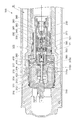
図2は、本発明の実施の形態に係るフロントフォーク21の断面図である。
本実施の形態に係るフロントフォーク21は、自動二輪車1の車両本体10と前輪2との間に配置されて前輪2を支えるとともに、後述するアウタ部材110が前輪2側にインナチューブ210が車両本体10側に配置された、所謂正立型のフロントフォークである。
<Configuration of front fork 21>
Next, the front fork 21 will be described in detail.
FIG. 2 is a cross-sectional view of the front fork 21 according to the embodiment of the present invention.
The front fork 21 according to the present embodiment is disposed between the vehicle body 10 and the front wheel 2 of the motorcycle 1 to support the front wheel 2, and an outer member 110 described later has an inner tube 210 on the front wheel 2 side. This is a so-called upright front fork disposed on the 10 side.

フロントフォーク21は、アウタ部材110を有して前輪2の車軸に取り付けられる車軸側ユニット100と、インナチューブ210を有して車両本体10に取り付けられる本体側ユニット200と、を備えている。また、フロントフォーク21は、車軸側ユニット100と本体側ユニット200との間に配置されて、路面の凸凹に伴い前輪2が受ける振動を吸収するスプリング500を備えている。   The front fork 21 includes an axle-side unit 100 that has an outer member 110 and is attached to the axle of the front wheel 2, and a body-side unit 200 that has an inner tube 210 and is attached to the vehicle body 10. Further, the front fork 21 includes a spring 500 that is disposed between the axle side unit 100 and the main body side unit 200 and absorbs vibrations received by the front wheels 2 due to unevenness of the road surface.

アウタ部材110及びインナチューブ210は、同軸的に配置された円筒状の部材であり、この円筒の中心線の方向(軸方向)を、以下では「上下方向」と称する場合がある。かかる場合、車両本体10側が「上」側、前輪2側が「下」側である。そして、フロントフォーク21は、車軸側ユニット100と本体側ユニット200とが上下方向(軸方向)に相対的に移動することにより、前輪2を支持しながら路面の凸凹を吸収して振動を抑制する。   The outer member 110 and the inner tube 210 are coaxially arranged cylindrical members, and the direction of the center line (axial direction) of the cylinder may be referred to as “vertical direction” below. In this case, the vehicle body 10 side is the “upper” side, and the front wheel 2 side is the “lower” side. The front fork 21 suppresses vibration by absorbing the unevenness of the road surface while supporting the front wheel 2 by relatively moving the axle side unit 100 and the main body side unit 200 in the vertical direction (axial direction). .

[車軸側ユニット100の構成]
車軸側ユニット100は、前輪2の車軸に取り付けられるアウタ部材110と、オイルの粘性抵抗を利用した減衰力を発生する減衰力発生ユニット130と、減衰力発生ユニット130を保持するロッド150と、ロッド150の下端部を保持するロッド保持部材160とを備えている。
また、車軸側ユニット100は、ロッド保持部材160の後述する軸方向凹部161aに挿入された球状のボール166と、ボール166の移動を制限する制限部材167とを備えている。
また、車軸側ユニット100は、前輪側スプリング500の下端部を支持するスプリング支持部材170と、スプリング支持部材170を保持する支持部材保持部材180と、インナチューブ210の軸方向の移動を案内する案内部材190とを備えている。
[Configuration of Axle Side Unit 100]
The axle-side unit 100 includes an outer member 110 attached to the axle of the front wheel 2, a damping force generation unit 130 that generates a damping force using the viscous resistance of oil, a rod 150 that holds the damping force generation unit 130, a rod 150, and a rod holding member 160 that holds the lower end of 150.
In addition, the axle side unit 100 includes a spherical ball 166 inserted into an axial recess 161a (described later) of the rod holding member 160, and a limiting member 167 that limits the movement of the ball 166.
The axle-side unit 100 also includes a spring support member 170 that supports the lower end of the front-wheel spring 500, a support member holding member 180 that holds the spring support member 170, and a guide that guides the axial movement of the inner tube 210. Member 190.

(減衰力発生ユニット130の構成)
減衰力発生ユニット130は、後述するシリンダ230の内側の空間に形成された作動油室50内を区画するピストン131と、ピストン131の上端側に設けられた上端側バルブ136と、ピストン131の下端側に設けられた下端側バルブ137とを備えている。また、減衰力発生ユニット130は、ピストン131、上端側バルブ136及び下端側バルブ137などを支持するピストンボルト140と、ピストンボルト140に締め付けられてピストン131、上端側バルブ136及び下端側バルブ137などの位置を定めるナット145とを備えている。
(Configuration of damping force generation unit 130)
The damping force generation unit 130 includes a piston 131 that defines a hydraulic oil chamber 50 formed in a space inside a cylinder 230, which will be described later, an upper end valve 136 that is provided on the upper end side of the piston 131, and a lower end of the piston 131. The lower end side valve | bulb 137 provided in the side is provided. Further, the damping force generation unit 130 includes a piston bolt 140 that supports the piston 131, the upper end side valve 136, the lower end side valve 137, and the like, and is fastened to the piston bolt 140 so that the piston 131, the upper end side valve 136, the lower end side valve 137, and the like. And a nut 145 for determining the position of.

ピストン131は、円筒状の部材であって、外周面に、シリンダ230との間の隙間をシールするシール部材を有している。ピストン131には、軸方向の貫通孔である第1貫通孔132及び第2貫通孔133が形成されている。また、ピストン131には、上端部にて径方向に延びて形成されると共に第1貫通孔132に連通する第1径方向連通路134と、下端部にて径方向に延びて形成されると共に第2貫通孔133に連通する第2径方向連通路135とが形成される。第1貫通孔132及び第2貫通孔133は、それぞれ周方向に等間隔に複数(例えば3つ)形成されており、第1径方向連通路134,第2径方向連通路135は、それぞれ第1貫通孔132,第2貫通孔133に対応する位置に形成されている。   The piston 131 is a cylindrical member, and has a seal member that seals the gap between the piston 131 and the cylinder 230 on the outer peripheral surface. The piston 131 is formed with a first through hole 132 and a second through hole 133 that are axial through holes. In addition, the piston 131 is formed to extend in the radial direction at the upper end portion and is formed to extend in the radial direction at the lower end portion, and a first radial communication path 134 communicating with the first through hole 132. A second radial communication path 135 communicating with the second through hole 133 is formed. A plurality of (for example, three) first through holes 132 and second through holes 133 are formed at equal intervals in the circumferential direction. The first radial communication path 134 and the second radial communication path 135 are respectively It is formed at a position corresponding to the first through hole 132 and the second through hole 133.

ピストンボルト140は、上端側に設けられた円柱状の軸部141と、下端側に設けられるとともに軸部141の半径よりも大きな半径の円柱状の基部142とを有する。ピストンボルト140には、基部142の下端面から軸部141にかけて凹んだ凹部143が形成されている。凹部143における上端部には、軸部141の外側と凹部143とを連通するように径方向に貫通された径方向貫通孔144が形成されている。   The piston bolt 140 has a columnar shaft portion 141 provided on the upper end side, and a columnar base portion 142 provided on the lower end side and having a radius larger than the radius of the shaft portion 141. The piston bolt 140 has a recess 143 that is recessed from the lower end surface of the base portion 142 to the shaft portion 141. A radial through hole 144 is formed at the upper end of the concave portion 143 so as to penetrate the outer side of the shaft portion 141 and the concave portion 143 in the radial direction.

ナット145には、上端部に、ピストンボルト140の雄ねじが締め付けられる雌ねじ146が形成され、雌ねじ146よりも下方には、下端面から凹むとともに雌ねじ146の谷の半径よりも大きな半径の円柱状の凹部147が形成されている。また、ナット145には、ナット145の外部と凹部147とを連通するように径方向に貫通された径方向貫通孔148が形成されている。   The nut 145 is formed with a female screw 146 to which the male screw of the piston bolt 140 is fastened at the upper end, and is formed in a cylindrical shape having a radius that is recessed from the lower end surface and larger than the radius of the valley of the female screw 146 below the female screw 146. A recess 147 is formed. Further, the nut 145 is formed with a radial through hole 148 that is penetrated in the radial direction so as to communicate the outside of the nut 145 with the recess 147.

以上のように構成された減衰力発生ユニット130は、ピストンボルト140の凹部143に形成された雌ねじにロッド150の上端部に形成された雄ねじが締め付けられることでロッド150に保持される。そして、ピストン131が、その外周面に設けられたシール部材を介してシリンダ230の内周面に接触し、シリンダ230内の空間を、ピストン131よりも上方の第1油室51と、ピストンよりも下方の第2油室52とに区画する。   The damping force generation unit 130 configured as described above is held by the rod 150 by tightening the male screw formed at the upper end of the rod 150 to the female screw formed in the recess 143 of the piston bolt 140. The piston 131 comes into contact with the inner peripheral surface of the cylinder 230 via a seal member provided on the outer peripheral surface thereof, and the space in the cylinder 230 is separated from the first oil chamber 51 above the piston 131 and the piston. Is also divided into a lower second oil chamber 52.

(ロッド保持部材160の構成)
ロッド保持部材160は、それぞれ径が異なる複数の円柱状の部位を有する部材であり、上端部にある上端側円柱状部161と、下端部にある下端側円柱状部162と、上端側円柱状部161と下端側円柱状部162との間にある中間円柱状部163とを有している。
(Configuration of rod holding member 160)
The rod holding member 160 is a member having a plurality of cylindrical portions each having a different diameter. The upper end side cylindrical portion 161 at the upper end portion, the lower end side cylindrical portion 162 at the lower end portion, and the upper end side cylindrical shape. An intermediate cylindrical portion 163 located between the portion 161 and the lower-end-side cylindrical portion 162.

上端側円柱状部161には、上端面から軸方向に凹んだ軸方向凹部161aと、外周面から径方向に全周に渡って凹んだ径方向凹部161bと、軸方向凹部161aと径方向凹部161bとを径方向に貫通する径方向貫通孔161cとが形成されている。
また、軸方向凹部161aには、内径が下方に行くに従って徐々に小さくなるように軸方向に対して傾斜した傾斜面161eが形成されている。
The upper cylindrical portion 161 includes an axial recess 161a that is recessed in the axial direction from the upper end surface, a radial recess 161b that is recessed from the outer peripheral surface in the radial direction over the entire circumference, and the axial recess 161a and the radial recess. A radial through hole 161c that penetrates 161b in the radial direction is formed.
The axial recess 161a is formed with an inclined surface 161e that is inclined with respect to the axial direction so that the inner diameter gradually decreases as it goes downward.

(支持部材保持部材180の構成)
支持部材保持部材180は、円筒状の部材であり、支持部材保持部材180には、軸方向の位置においてロッド保持部材160の径方向凹部161bに対応する位置に、内外を連通する連通孔182が形成されている。
(Configuration of Support Member Holding Member 180)
The support member holding member 180 is a cylindrical member, and the support member holding member 180 has a communication hole 182 communicating with the inside and outside at a position corresponding to the radial recess 161b of the rod holding member 160 in the axial position. Is formed.

以上のように構成された車軸側ユニット100においては、アウタ部材110の内周面と、ロッド150や支持部材保持部材180の外周面との間には、フロントフォーク21内に密封されたオイルを貯留するリザーバ室40(貯留室)が形成される。   In the axle-side unit 100 configured as described above, oil sealed in the front fork 21 is placed between the inner peripheral surface of the outer member 110 and the outer peripheral surface of the rod 150 or the support member holding member 180. A reservoir chamber 40 (storage chamber) for storage is formed.

[本体側ユニット200の構成]
本体側ユニット200は、両端が開口した円筒状のインナチューブ210と、インナチューブ210における上端部に取り付けられたキャップ220と、を備えている。
また、本体側ユニット200は、円筒状のシリンダ230と、シリンダ230における下端部に取り付けられてシリンダ230内の空間を密封する密封部材240とを備えている。
また、本体側ユニット200は、前輪側スプリング500の上端部を支持するとともに前輪側スプリング500の長さを調整(変更)する前輪側スプリング長変更ユニット250と、シリンダ230における上端部に取り付けられてオイルの流路を切り替える前輪側流路切替ユニット300とを備えている。
また、本体側ユニット200は、前輪側スプリング長変更ユニット250の後述するベース部材260に対する上端部支持部材270の相対位置を検出する前輪側相対位置検出部281(図11参照)を有している。
[Configuration of main unit 200]
The main unit 200 includes a cylindrical inner tube 210 having both ends opened, and a cap 220 attached to the upper end of the inner tube 210.
The main unit 200 includes a cylindrical cylinder 230 and a sealing member 240 that is attached to the lower end of the cylinder 230 and seals the space in the cylinder 230.
The main unit 200 is attached to the front wheel side spring length changing unit 250 that supports the upper end part of the front wheel side spring 500 and adjusts (changes) the length of the front wheel side spring 500, and the upper end part of the cylinder 230. And a front-wheel-side channel switching unit 300 that switches the oil channel.
The main unit 200 has a front wheel side relative position detection unit 281 (see FIG. 11) that detects the relative position of the upper end support member 270 with respect to a base member 260 described later of the front wheel side spring length changing unit 250. .

(キャップ220の構成)
キャップ220は略円筒状の部材である。キャップ220の外周面には、インナチューブ210に形成された雌ねじ213に締め付けられる雄ねじ221が形成され、内周面には、前輪側スプリング長変更ユニット250や前輪側流路切替ユニット300に形成された雄ねじが締め付けられる雌ねじが形成されている。そして、キャップ220は、インナチューブ210に取り付けられるとともに、前輪側スプリング長変更ユニット250や前輪側流路切替ユニット300を保持する。
また、キャップ220は、インナチューブ210の内部空間を液密に保つためのOリング222を有している。
(Configuration of cap 220)
The cap 220 is a substantially cylindrical member. A male screw 221 fastened to a female screw 213 formed on the inner tube 210 is formed on the outer peripheral surface of the cap 220, and formed on the front wheel side spring length changing unit 250 and the front wheel side flow path switching unit 300 on the inner peripheral surface. A female screw to which the male screw is tightened is formed. The cap 220 is attached to the inner tube 210 and holds the front wheel side spring length changing unit 250 and the front wheel side flow path switching unit 300.
The cap 220 has an O-ring 222 for keeping the inner space of the inner tube 210 liquid-tight.

(前輪側スプリング長変更ユニット250の構成)
前輪側スプリング長変更ユニット250は、キャップ220に固定されたベース部材260と、前輪側スプリング500の上端部を支持するとともにベース部材260に対して軸方向に相対移動することで前輪側スプリング500の長さを変更する上端部支持部材270とを備えている。
(Configuration of front wheel side spring length changing unit 250)
The front-wheel-side spring length changing unit 250 supports the base member 260 fixed to the cap 220 and the upper end of the front-wheel-side spring 500 and moves relative to the base member 260 in the axial direction, thereby And an upper end support member 270 that changes the length.

ベース部材260は、略円筒状の部材である。ベース部材260の上端部は、周方向の一部が径方向に突出した突出部260bが形成されており、突出部260bの内側と、後述する支持部材400の下端部における外周面との間に、シリンダ230内のオイルをリザーバ室40へ排出する排出流路41を形成する。また、ベース部材260の内周面とシリンダ230の外周面との間には、環状の環状流路61が形成される。   The base member 260 is a substantially cylindrical member. The upper end portion of the base member 260 is formed with a protruding portion 260b in which a part of the circumferential direction protrudes in the radial direction, and between the inner side of the protruding portion 260b and the outer peripheral surface of the lower end portion of the support member 400 described later. A discharge passage 41 for discharging the oil in the cylinder 230 to the reservoir chamber 40 is formed. In addition, an annular channel 61 is formed between the inner peripheral surface of the base member 260 and the outer peripheral surface of the cylinder 230.

上端部支持部材270は、円筒状の円筒状部271と、円筒状部271における下端部から半径方向の内側に向かうように形成された内向部272とを有している。上端部支持部材270は、シリンダ230の外周面及びベース部材260の下端部との間の空間に、ベース部材260に対する上端部支持部材270の位置を変更するオイルを収容するジャッキ室60を形成する。   The upper end support member 270 has a cylindrical cylindrical portion 271 and an inward portion 272 formed so as to go radially inward from the lower end portion of the cylindrical portion 271. The upper end support member 270 forms a jack chamber 60 that accommodates oil for changing the position of the upper end support member 270 relative to the base member 260 in a space between the outer peripheral surface of the cylinder 230 and the lower end portion of the base member 260. .

円筒状部271には、この円筒状部271の内外を連通するように径方向に貫通した径方向貫通孔273が形成されている。この径方向貫通孔273を介してオイルがジャッキ室60からリザーバ室40へ排出されることにより、ベース部材260に対する上端部支持部材270の移動量が制限される。
また、ジャッキ室60へは、ベース部材260の内周面とシリンダ230の外周面との間に形成された環状流路61を介してシリンダ230内のオイルが供給される。その詳細については後で詳述する。
The cylindrical portion 271 is formed with a radial through hole 273 penetrating in the radial direction so as to communicate the inside and outside of the cylindrical portion 271. The oil is discharged from the jack chamber 60 to the reservoir chamber 40 through the radial through-hole 273, whereby the amount of movement of the upper end support member 270 relative to the base member 260 is limited.
Further, the oil in the cylinder 230 is supplied to the jack chamber 60 via an annular channel 61 formed between the inner peripheral surface of the base member 260 and the outer peripheral surface of the cylinder 230. Details thereof will be described later.

(前輪側相対位置検出部281の構成)
前輪側相対位置検出部281(図11参照)は、ベース部材260に対する上端部支持部材270の上下方向への移動量、言い換えれば車体フレーム11に対する上端部支持部材270の上下方向への移動量を検出する物であることを例示することができる。例えば、ベース部材260の外周面にコイルを巻くとともに、上端部支持部材270を磁性体とし、ベース部材260に対する上端部支持部材270の上下方向への移動に応じて変化するコイルのインピーダンスに基づいて上端部支持部材270の移動量を検出する物であることを例示することができる。
(Configuration of Front Wheel Side Relative Position Detection Unit 281)
The front wheel side relative position detection unit 281 (see FIG. 11) indicates the amount of movement of the upper end support member 270 in the vertical direction relative to the base member 260, in other words, the amount of movement of the upper end support member 270 in the vertical direction relative to the vehicle body frame 11. It can be exemplified that it is an object to be detected. For example, a coil is wound around the outer peripheral surface of the base member 260, and the upper end support member 270 is made of a magnetic material. Based on the impedance of the coil that changes according to the vertical movement of the upper end support member 270 relative to the base member 260, It can be exemplified that it is an object for detecting the amount of movement of the upper end support member 270.

(前輪側流路切替ユニット300の構成)
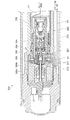
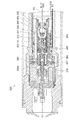
図3は、図2のIII部の拡大図である。
図4は、図3のIV部の拡大図である。
前輪側流路切替ユニット300は、後述するポンプ600にて吐出されたオイルをリザーバ室40へ供給するか、ポンプ600にて吐出されたオイルをジャッキ室60へ供給するか、ジャッキ室60に収容されたオイルをリザーバ室40へ供給するかを切り替える装置である。
(Configuration of front wheel side flow path switching unit 300)
FIG. 3 is an enlarged view of a portion III in FIG.
FIG. 4 is an enlarged view of a portion IV in FIG.
The front wheel side flow path switching unit 300 supplies oil discharged from a pump 600 described later to the reservoir chamber 40, supplies oil discharged from the pump 600 to the jack chamber 60, or accommodates in the jack chamber 60. It is a device for switching whether to supply the oil to the reservoir chamber 40.

前輪側流路切替ユニット300は、前輪側ソレノイド310と、球状の弁体321と、弁体321を押す棒状のプッシュロッド322と、弁体321の座面を有する弁体シート部材330と、コイルスプリング340と、コイルスプリング340のバネ力を受けて弁体321を座面に押し付ける押付部材350とを備えている。   The front wheel side flow path switching unit 300 includes a front wheel side solenoid 310, a spherical valve body 321, a rod-like push rod 322 that presses the valve body 321, a valve body seat member 330 having a seat surface of the valve body 321, a coil A spring 340 and a pressing member 350 that receives the spring force of the coil spring 340 and presses the valve body 321 against the seat surface are provided.

また、前輪側流路切替ユニット300は、球状のボール360と、ボール360に対して軸方向の付勢力を与えるコイルスプリング361と、ボール360とコイルスプリング361との間に介在する円板362と、を備えている。また、前輪側流路切替ユニット300は、ボール360の座面を有するボールシート部材365と、コイルスプリング361及び円板362を収容する収容部材370とを備えている。
また、前輪側流路切替ユニット300は、弁体321や弁体シート部材330などを収容するバルブ収容内側部材380と、バルブ収容内側部材380の外側に配置されてボール360やボールシート部材365などを収容するバルブ収容外側部材390と、バルブ収容内側部材380及びバルブ収容外側部材390を支持する支持部材400とを備えている。
また、前輪側流路切替ユニット300は、前輪側ソレノイド310の後述する作動ロッド314の下端部に装着され、前輪側ソレノイド310の推力をプッシュロッド322に伝達する伝達部材410と、伝達部材410に対して軸方向の付勢力を与えるコイルスプリング415とを備えている。
The front wheel side flow path switching unit 300 includes a spherical ball 360, a coil spring 361 that applies an urging force in the axial direction to the ball 360, and a disk 362 that is interposed between the ball 360 and the coil spring 361. It is equipped with. Further, the front wheel side flow path switching unit 300 includes a ball seat member 365 having a seating surface of the ball 360, and a housing member 370 for housing the coil spring 361 and the disc 362.
The front wheel side flow path switching unit 300 includes a valve housing inner member 380 that houses the valve body 321, the valve body seat member 330, and the like, and a ball 360, a ball seat member 365, and the like that are disposed outside the valve housing inner member 380. And a support member 400 for supporting the valve housing inner member 380 and the valve housing outer member 390.
The front wheel side flow path switching unit 300 is attached to a lower end portion of a later-described operation rod 314 of the front wheel side solenoid 310, and transmits a thrust of the front wheel side solenoid 310 to the push rod 322. A coil spring 415 that applies an urging force in the axial direction is provided.

<前輪側ソレノイド310の構成>
前輪側ソレノイド310は、コイル311と、コイル311の内側に配置されたコア312と、コア312に案内されるプランジャ313と、プランジャ313に連結された作動ロッド314とを備えた、比例ソレノイドである。
また、前輪側ソレノイド310は、コイル311、コア312及びプランジャ313などを収容するケース315と、ケース315の開口部を覆うカバー316とを備えている。
<Configuration of front wheel side solenoid 310>
The front wheel side solenoid 310 is a proportional solenoid including a coil 311, a core 312 disposed inside the coil 311, a plunger 313 guided by the core 312, and an operating rod 314 coupled to the plunger 313. .
The front wheel side solenoid 310 includes a case 315 that houses the coil 311, the core 312, the plunger 313, and the like, and a cover 316 that covers the opening of the case 315.

ケース315は、円筒状の円筒状部315aと、円筒状部315aにおける下端部から半径方向の内側に向かうように形成された内向部315bとを有している。内向部315bには、作動ロッド314を通す貫通孔が形成されているとともに作動ロッド314の移動をガイドするガイドブッシュ315cが嵌め込まれている。   The case 315 has a cylindrical cylindrical portion 315a and an inward portion 315b formed so as to be directed radially inward from the lower end portion of the cylindrical portion 315a. A through hole through which the operating rod 314 passes is formed in the inward portion 315b, and a guide bush 315c that guides the movement of the operating rod 314 is fitted therein.

作動ロッド314は、中空であり、上端部はケース315の内部に収容され、下端部はケース315から突出している。そして、作動ロッド314におけるケース315から突出した部位には、バルブ収容内側部材380に形成された後述する流路を開閉する円板状のバルブ317が取り付けられている。また、バルブ317とケース315との間における作動ロッド314の周囲には、バルブ317に対して軸方向の付勢力を与えるコイルスプリング318が取り付けられている。   The operating rod 314 is hollow, the upper end portion is accommodated in the case 315, and the lower end portion protrudes from the case 315. A disk-shaped valve 317 that opens and closes a flow path, which will be described later, formed in the valve housing inner member 380 is attached to a portion of the operating rod 314 that protrudes from the case 315. A coil spring 318 that applies an urging force in the axial direction to the valve 317 is attached around the operating rod 314 between the valve 317 and the case 315.

以上のように構成された前輪側ソレノイド310は、キャップ220に装着されたコネクタ、リード線を介してコイル311に通電されることにより、通電電流に応じてプランジャ313に軸方向の推力が発生する。そして、プランジャ313の推力によってプランジャ313に連結された作動ロッド314が軸方向に移動する。本実施の形態に係る前輪側ソレノイド310は、コイル311への通電電流が大きくなるほど作動ロッド314のケース315からの突出量が大きくなるようにプランジャ313に軸方向の推力が発生する。
なお、コイル311への通電量は制御装置70にて制御される。
The front-wheel side solenoid 310 configured as described above is energized to the coil 311 via the connector and lead wire attached to the cap 220, so that axial thrust is generated in the plunger 313 according to the energized current. . Then, the operating rod 314 connected to the plunger 313 is moved in the axial direction by the thrust of the plunger 313. The front wheel side solenoid 310 according to the present embodiment generates axial thrust on the plunger 313 so that the amount of protrusion of the operating rod 314 from the case 315 increases as the current flowing to the coil 311 increases.
The energization amount to the coil 311 is controlled by the control device 70.

<弁体シート部材330の構成>
弁体シート部材330は、外径が下方に行くに従って徐々に大きくなるように軸方向に対して傾斜した傾斜面331を有する円錐状の円錐状部332と、円柱状の円柱状部333とを有する。
<Configuration of valve body sheet member 330>
The valve seat member 330 includes a conical conical portion 332 having an inclined surface 331 inclined with respect to the axial direction so that the outer diameter gradually increases as it goes downward, and a cylindrical columnar portion 333. Have.

円錐状部332の内部には、上端面から凹んだ上端側凹部334が形成されている。また、円柱状部333の内部には、下端面から凹んだ下端側凹部335と、この下端側凹部335と上端側凹部334とを連通する連通孔336が形成されている。   Inside the conical portion 332, an upper end side recess 334 that is recessed from the upper end surface is formed. Further, inside the cylindrical portion 333, a lower end side recess 335 that is recessed from the lower end surface, and a communication hole 336 that communicates the lower end side recess 335 and the upper end side recess 334 are formed.

下端側凹部335は、半径が下方に行くに従って徐々に大きくなるように軸方向に対して傾斜した傾斜面335aを有する円錐状の円錐状凹部335bと、円柱状の円柱状凹部335cとを有する。
円錐状部332の外周面には、全周に渡って凹んだ溝332aが形成されている。溝332aに、バルブ収容内側部材380との間の隙間をシールするOリング337が嵌め込まれている。
The lower end side recess 335 includes a conical conical recess 335b having an inclined surface 335a inclined with respect to the axial direction so that the radius gradually increases as it goes downward, and a cylindrical columnar recess 335c.
On the outer circumferential surface of the conical portion 332, a groove 332a that is recessed over the entire circumference is formed. An O-ring 337 that seals the gap with the valve housing inner member 380 is fitted in the groove 332a.

<バルブ収容内側部材380の構成>
バルブ収容内側部材380は、概略、上端部にフランジ部が形成された円柱状の部材である。バルブ収容内側部材380には、上端面から凹んだ上端側凹部381と、下端面から凹んだ下端側凹部382と、上端側凹部381と下端側凹部382とを連通する連通孔383とが形成されている。また、バルブ収容内側部材380の外周面には、全周に渡って径方向に凹んだ第1径方向凹部384と第2径方向凹部385とが形成されている。
<Configuration of Valve Housing Inner Member 380>
The valve housing inner member 380 is generally a columnar member having a flange portion formed at the upper end portion. The valve housing inner member 380 is formed with an upper end side recess 381 that is recessed from the upper end surface, a lower end side recess 382 that is recessed from the lower end surface, and a communication hole 383 that communicates the upper end side recess 381 and the lower end side recess 382. ing. A first radial recess 384 and a second radial recess 385 are formed on the outer peripheral surface of the valve housing inner member 380 so as to be recessed in the radial direction over the entire circumference.

上端側凹部381は、伝達部材410及びコイルスプリング415を収容するように、円柱状に形成されている。
下端側凹部382は、円柱状で径が互いに異なる第1円柱状凹部382a及び第2円柱状凹部382bと、第1円柱状凹部382aと第2円柱状凹部382bとの間に形成され半径が下方に行くに従って徐々に大きくなるように軸方向に対して傾斜した傾斜面を有する円錐状の円錐状凹部382cとを有する。
The upper end side recess 381 is formed in a columnar shape so as to accommodate the transmission member 410 and the coil spring 415.
The lower end side concave portion 382 is formed between the first cylindrical concave portion 382a and the second cylindrical concave portion 382b, which are cylindrical and have different diameters, and the radius is lower between the first cylindrical concave portion 382a and the second cylindrical concave portion 382b. And a conical conical recess 382c having an inclined surface inclined with respect to the axial direction so as to gradually increase as it goes to.

また、バルブ収容内側部材380には、下端側凹部382の第1円柱状凹部382aと第1径方向凹部384とを連通する径方向の貫通孔である第1径方向連通孔387が形成されている。第1径方向連通孔387は、周方向に等間隔に複数形成されている。
また、バルブ収容内側部材380には、第2円柱状凹部382bとバルブ収容内側部材380の外側とを連通する径方向の貫通孔である第2径方向連通孔388が形成されている。第2径方向連通孔388は、周方向に等間隔に複数形成されている。
In addition, the valve housing inner member 380 is formed with a first radial communication hole 387 that is a radial through hole that communicates the first cylindrical recess 382 a of the lower end recess 382 and the first radial recess 384. Yes. A plurality of first radial communication holes 387 are formed at equal intervals in the circumferential direction.
Further, the valve housing inner member 380 is formed with a second radial communication hole 388 that is a radial through hole that communicates the second columnar recess 382b and the outside of the valve housing inner member 380. A plurality of second radial communication holes 388 are formed at equal intervals in the circumferential direction.

また、バルブ収容内側部材380には、上端面と第1径方向凹部384とを連通する軸方向の貫通孔である内側軸方向連通孔389aが形成されている。内側軸方向連通孔389aは、周方向に等間隔に複数形成されている。
また、バルブ収容内側部材380のフランジ部には、このフランジ部を軸方向に貫通する貫通孔である外側軸方向連通孔389bが形成されている。外側軸方向連通孔389bは、周方向に等間隔に複数形成されている。
The valve housing inner member 380 is formed with an inner axial communication hole 389a that is an axial through hole that communicates the upper end surface with the first radial recess 384. A plurality of inner axial communication holes 389a are formed at equal intervals in the circumferential direction.
The flange portion of the valve housing inner member 380 is formed with an outer axial communication hole 389b that is a through hole penetrating the flange portion in the axial direction. A plurality of outer axial communication holes 389b are formed at equal intervals in the circumferential direction.

<バルブ収容外側部材390の構成>
バルブ収容外側部材390は、円筒状でそれぞれ外径が互いに異なる第1円筒状部391及び第2円筒状部392と、第1円筒状部391における上端部から半径方向に外側に向かうフランジ部とを有している。第1円筒状部391の外径は第2円筒状部392の外径よりも大きい。
バルブ収容外側部材390には、上端面から凹んだ上端面側凹部393が形成されている。
第1円筒状部391には、第1円筒状部391の下方であって第2円筒状部392の外周面とシリンダ230の内周面との間に形成された空間と、上端面側凹部393とを連通する軸方向の貫通孔である軸方向連通孔394が形成されている。軸方向連通孔394は、周方向に等間隔に複数形成されている。
<Configuration of Valve Housing Outer Member 390>
The valve housing outer member 390 includes a first cylindrical portion 391 and a second cylindrical portion 392 that are cylindrical and have different outer diameters, and a flange portion that radially outwards from the upper end portion of the first cylindrical portion 391. have. The outer diameter of the first cylindrical portion 391 is larger than the outer diameter of the second cylindrical portion 392.
The valve housing outer member 390 is formed with an upper end surface side recess 393 that is recessed from the upper end surface.
The first cylindrical portion 391 includes a space formed below the first cylindrical portion 391 and between the outer peripheral surface of the second cylindrical portion 392 and the inner peripheral surface of the cylinder 230, and an upper end surface side concave portion. An axial communication hole 394 which is an axial through hole communicating with 393 is formed. A plurality of axial communication holes 394 are formed at equal intervals in the circumferential direction.

また、第1円筒状部391には、内部と外部とを連通する径方向の貫通孔である第1径方向連通孔397及び第2径方向連通孔398が形成されている。第1径方向連通孔397及び第2径方向連通孔398は、周方向に等間隔に、軸方向連通孔394が形成されていない部位に複数形成されている。   In addition, the first cylindrical portion 391 is formed with a first radial communication hole 397 and a second radial communication hole 398 that are radial through holes that communicate the inside and the outside. A plurality of first radial communication holes 397 and second radial communication holes 398 are formed at equal intervals in the circumferential direction at portions where the axial communication holes 394 are not formed.

以上のように構成された前輪側流路切替ユニット300においては、前輪側ソレノイド310のコイル311への通電が停止しているか又は予め定められた第1基準電流未満の電流が供給されている場合には、作動ロッド314に取り付けられたバルブ317がバルブ収容内側部材380の上端面に着座せずに、バルブ収容内側部材380に形成された内側軸方向連通孔389aの上端側の開口を開放する。   In the front wheel side flow path switching unit 300 configured as described above, the energization to the coil 311 of the front wheel side solenoid 310 is stopped or a current less than a predetermined first reference current is supplied. The valve 317 attached to the actuating rod 314 does not sit on the upper end surface of the valve accommodating inner member 380, and opens the upper end side opening of the inner axial communication hole 389a formed in the valve accommodating inner member 380. .

他方、前輪側ソレノイド310のコイル311へ第1基準電流以上の電流が供給されている場合には、作動ロッド314が下方に移動し、作動ロッド314に取り付けられたバルブ317がバルブ収容内側部材380の上端面に着座して内側軸方向連通孔389aの上端側の開口を閉じる。   On the other hand, when a current greater than or equal to the first reference current is supplied to the coil 311 of the front-wheel side solenoid 310, the operating rod 314 moves downward, and the valve 317 attached to the operating rod 314 is connected to the valve housing inner member 380. The upper end of the inner axial communication hole 389a is closed.

そして、前輪側ソレノイド310のコイル311へ、第1基準電流よりも大きい予め定められた第2基準電流以上の電流が供給されている場合には、作動ロッド314がさらに下方に移動して伝達部材410を介してプッシュロッド322を下方へ押す。プッシュロッド322が下方へ移動すると、弁体321がプッシュロッド322から押されて弁体シート部材330の下端側凹部335の傾斜面335aから離れる。   When the coil 311 of the front wheel side solenoid 310 is supplied with a current greater than a predetermined second reference current larger than the first reference current, the operating rod 314 moves further downward to transmit the transmission member. Push the push rod 322 downward through 410. When the push rod 322 moves downward, the valve body 321 is pushed from the push rod 322 and is separated from the inclined surface 335 a of the lower end side recess 335 of the valve body sheet member 330.

以下では、コイル311への通電が停止しているか又は第1基準電流未満の電流が供給されている場合に、作動ロッド314に取り付けられたバルブ317がバルブ収容内側部材380に形成された内側軸方向連通孔389aを開放するとともに弁体321が弁体シート部材330の下端側凹部335の傾斜面335aに着座している状態を第1切替状態と称す。   In the following, when the coil 311 is de-energized or supplied with a current less than the first reference current, the valve 317 attached to the operating rod 314 is formed on the valve housing inner member 380. A state in which the direction communication hole 389a is opened and the valve body 321 is seated on the inclined surface 335a of the lower end side recess 335 of the valve body seat member 330 is referred to as a first switching state.

また、コイル311へ第1基準電流以上であって第2基準電流未満の電流が供給され、作動ロッド314に取り付けられたバルブ317がバルブ収容内側部材380に形成された内側軸方向連通孔389aを閉じるとともに弁体321が弁体シート部材330の下端側凹部335の傾斜面335aに着座している状態を第2切替状態と称す。   The coil 311 is supplied with a current that is greater than or equal to the first reference current and less than the second reference current, and the valve 317 attached to the operating rod 314 passes through the inner axial communication hole 389 a formed in the valve housing inner member 380. A state in which the valve body 321 is closed and is seated on the inclined surface 335 a of the lower end side recess 335 of the valve body seat member 330 is referred to as a second switching state.

また、コイル311へ第2基準電流以上であって第3基準電流未満の電流が供給され、作動ロッド314に取り付けられたバルブ317がバルブ収容内側部材380に形成された内側軸方向連通孔389aを閉じるとともに弁体321が弁体シート部材330の下端側凹部335の傾斜面335aから離れている状態を第3切替状態と称す。
なお、第1基準電流、第2基準電流は、それぞれ0.1A、0.5Aであることを例示することができる。また、前輪側ソレノイド310のコイル311に流れる最大電流は、3.2Aであることを例示することができる。
The coil 311 is supplied with a current that is greater than or equal to the second reference current and less than the third reference current, and the valve 317 attached to the operating rod 314 passes through the inner axial communication hole 389 a formed in the valve housing inner member 380. A state in which the valve body 321 is closed and separated from the inclined surface 335a of the lower end side recess 335 of the valve body sheet member 330 is referred to as a third switching state.
It can be exemplified that the first reference current and the second reference current are 0.1 A and 0.5 A, respectively. Further, it can be exemplified that the maximum current flowing through the coil 311 of the front wheel side solenoid 310 is 3.2A.

また、コイル311へ第3基準電流以上の電流が供給され、作動ロッド314に取り付けられたバルブ317がバルブ収容内側部材380に形成された内側軸方向連通孔389aを閉じるとともに、弁体シート部材330の円錐状部332の傾斜面331がバルブ収容内側部材380の円錐状凹部382cに形成された傾斜面から離れている状態を第4切替状態と称す。なお、この第4切替状態においては、弁体321は弁体シート部材330の下端側凹部335の傾斜面335aに着座している。   In addition, a current equal to or greater than the third reference current is supplied to the coil 311, and the valve 317 attached to the operating rod 314 closes the inner axial communication hole 389 a formed in the valve housing inner member 380, and the valve body seat member 330. A state in which the inclined surface 331 of the conical portion 332 is separated from the inclined surface formed in the conical recess 382c of the valve housing inner member 380 is referred to as a fourth switching state. In the fourth switching state, the valve body 321 is seated on the inclined surface 335 a of the lower end side recess 335 of the valve body seat member 330.

<フロントフォーク21の作用>
以上のように構成されたフロントフォーク21は、前輪側スプリング500が自動二輪車1の車重を支えて衝撃を吸収し、減衰力発生ユニット130が前輪側スプリング500の振動を減衰する。
図5は、フロントフォーク21の圧縮行程時の作用を説明するための図である。
フロントフォーク21の圧縮行程においては、減衰力発生ユニット130のピストン131が、白抜き矢印のようにシリンダ230に対して上方へ移動し、ピストン131の移動で第1油室51内のオイルは押されて圧力が上昇する。その結果、第1貫通孔132を塞ぐ下端側バルブ137が開き、オイルは第1貫通孔132を通って第2油室52に流入する(矢印C1参照)。この第1油室51から第2油室52へのオイルの流れは、第1貫通孔132及び下端側バルブ137で絞られ、圧縮行程時における減衰力を得る。
<Operation of front fork 21>
In the front fork 21 configured as described above, the front wheel side spring 500 supports the weight of the motorcycle 1 to absorb the impact, and the damping force generation unit 130 attenuates the vibration of the front wheel side spring 500.
FIG. 5 is a diagram for explaining the operation of the front fork 21 during the compression stroke.
In the compression stroke of the front fork 21, the piston 131 of the damping force generation unit 130 moves upward with respect to the cylinder 230 as indicated by the white arrow, and the oil in the first oil chamber 51 is pushed by the movement of the piston 131. As a result, the pressure rises. As a result, the lower end side valve 137 that closes the first through hole 132 is opened, and the oil flows into the second oil chamber 52 through the first through hole 132 (see arrow C1). The flow of oil from the first oil chamber 51 to the second oil chamber 52 is throttled by the first through hole 132 and the lower end side valve 137 to obtain a damping force during the compression stroke.

また、圧縮行程時にシリンダ230内部へロッド150が進入したことに起因して、ロッド進入体積分のオイルが、前輪側流路切替ユニット300の切替状態に応じて、ジャッキ室60又はリザーバ室40へ供給される(矢印C2参照)。前輪側流路切替ユニット300の切替状態に応じて、ジャッキ室60、リザーバ室40のいずれへ供給されるかについては後述する。なお、減衰力発生ユニット130、ロッド150及びシリンダ230などは、シリンダ230内のオイルをジャッキ室60又はリザーバ室40へ供給するポンプとして機能する。以下では、このポンプを「ポンプ600」と称す場合もある。   Further, due to the rod 150 entering the cylinder 230 during the compression stroke, the oil corresponding to the rod entry volume flows into the jack chamber 60 or the reservoir chamber 40 according to the switching state of the front wheel side flow path switching unit 300. (See arrow C2). Which of the jack chamber 60 and the reservoir chamber 40 is supplied according to the switching state of the front wheel side flow path switching unit 300 will be described later. The damping force generation unit 130, the rod 150, the cylinder 230, and the like function as a pump that supplies oil in the cylinder 230 to the jack chamber 60 or the reservoir chamber 40. Hereinafter, this pump may be referred to as “pump 600”.

図6は、フロントフォーク21の伸張行程時の作用を説明するための図である。
フロントフォーク21の伸張行程においては、減衰力発生ユニット130のピストン131が、白抜き矢印のようにシリンダ230に対して下方へ移動し、ピストン131の移動で第2油室52内のオイルは押されて圧力が上昇する。その結果、第2貫通孔133を塞ぐ上端側バルブ136が開き、オイルは第2貫通孔133を通って第1油室51に流入する(矢印T1参照)。この第2油室52から第1油室51へのオイルの流れは、第2貫通孔133及び上端側バルブ136で絞られ、伸張行程時における減衰力を得る。
FIG. 6 is a diagram for explaining the operation of the front fork 21 during the extension stroke.
In the extension stroke of the front fork 21, the piston 131 of the damping force generation unit 130 moves downward with respect to the cylinder 230 as indicated by the white arrow, and the movement of the piston 131 causes the oil in the second oil chamber 52 to be pushed. As a result, the pressure rises. As a result, the upper end valve 136 that closes the second through hole 133 is opened, and the oil flows into the first oil chamber 51 through the second through hole 133 (see arrow T1). The flow of oil from the second oil chamber 52 to the first oil chamber 51 is throttled by the second through hole 133 and the upper end side valve 136 to obtain a damping force during the extension stroke.

また、伸張行程時にシリンダ230内部からロッド150が退出したことに起因して、ロッド退出体積分のオイルが、リザーバ室40から第1油室51へ供給される。つまり、ピストン131が下方へ移動したことに起因して低圧となった第1油室51へ、リザーバ室40のオイルが進入する。つまり、リザーバ室40のオイルは、支持部材保持部材180の連通孔182、ロッド保持部材160の径方向貫通孔161cを通ってロッド保持部材160の軸方向凹部161aに進入した後にボール166を上方へ移動させてロッド150内部へ進入する(矢印T2参照)。そして、ロッド150内部へ進入したオイルは、ピストンボルト140の凹部143,径方向貫通孔144、ナット145の径方向貫通孔148を通って第1油室51へ至る(矢印T3参照)。   Further, due to the rod 150 withdrawing from the cylinder 230 during the extension stroke, oil corresponding to the rod withdrawal volume is supplied from the reservoir chamber 40 to the first oil chamber 51. That is, the oil in the reservoir chamber 40 enters the first oil chamber 51 that has become a low pressure due to the piston 131 moving downward. That is, the oil in the reservoir chamber 40 enters the axial recess 161a of the rod holding member 160 through the communication hole 182 of the support member holding member 180 and the radial through hole 161c of the rod holding member 160 and then moves the ball 166 upward. Move to enter the rod 150 (see arrow T2). The oil that has entered the rod 150 reaches the first oil chamber 51 through the recess 143 of the piston bolt 140, the radial through hole 144, and the radial through hole 148 of the nut 145 (see arrow T3).

このように、支持部材保持部材180の連通孔182、ロッド保持部材160の径方向貫通孔161c、ロッド保持部材160の軸方向凹部161a、ロッド150内部、ピストンボルト140の凹部143,径方向貫通孔144、ナット145の径方向貫通孔148は、リザーバ室40からシリンダ230内(第1油室51)へオイルを吸入する吸入路として機能する。また、ボール166及びロッド保持部材160の軸方向凹部161aに形成された傾斜面161eは、リザーバ室40からロッド150内部へのオイルの流入を許容するとともにロッド150内部からリザーバ室40へのオイルの排出を抑制するチェック弁として機能する。   As described above, the communication hole 182 of the support member holding member 180, the radial through hole 161c of the rod holding member 160, the axial concave portion 161a of the rod holding member 160, the inside of the rod 150, the concave portion 143 of the piston bolt 140, the radial through hole. 144 and the radial through hole 148 of the nut 145 function as a suction path for sucking oil from the reservoir chamber 40 into the cylinder 230 (first oil chamber 51). In addition, the inclined surface 161e formed in the axial concave portion 161a of the ball 166 and the rod holding member 160 allows oil to flow from the reservoir chamber 40 into the rod 150, and allows oil to flow from the rod 150 into the reservoir chamber 40. It functions as a check valve that suppresses discharge.

<前輪側流路切替ユニット300の切替状態に応じたオイルの流通状態>
図7は、前輪側流路切替ユニット300が第1切替状態である場合のオイルの流通状態を示す図である。
フロントフォーク21の圧縮行程時に前輪側流路切替ユニット300が第1切替状態である場合、減衰力発生ユニット130、ロッド150及びシリンダ230などにより構成されるポンプ600から吐出されたオイルは、図7に示した矢印P1のように、バルブ収容外側部材390に形成された軸方向連通孔394を通って上方へ向かう。そして、バルブ収容外側部材390に形成された軸方向連通孔394を通って上方へ向かったオイルは、バルブ収容内側部材380の外側軸方向連通孔389bを通って上方へ向かい、開放された内側軸方向連通孔389aを通って下方へ向かう。その後、オイルは、バルブ収容外側部材390に形成された第1径方向連通孔397、ベース部材260の突出部260bと支持部材400の下端部との間に形成された排出流路41を通ってリザーバ室40に向かう。
<Oil distribution state according to the switching state of the front wheel side channel switching unit 300>
FIG. 7 is a diagram illustrating the oil circulation state when the front wheel side flow path switching unit 300 is in the first switching state.
When the front wheel side flow path switching unit 300 is in the first switching state during the compression stroke of the front fork 21, the oil discharged from the pump 600 including the damping force generation unit 130, the rod 150, the cylinder 230, and the like is as shown in FIG. As shown by the arrow P1 shown in FIG. 6, the valve housing outer member 390 is directed upward through the axial communication hole 394 formed in the valve housing outer member 390. Then, the oil directed upward through the axial communication hole 394 formed in the valve housing outer member 390 is directed upward through the outer axial communication hole 389b of the valve housing inner member 380, and the opened inner shaft It goes downward through the direction communication hole 389a. Thereafter, the oil passes through the first radial communication hole 397 formed in the valve housing outer member 390, and the discharge channel 41 formed between the protruding portion 260 b of the base member 260 and the lower end portion of the support member 400. Head toward reservoir chamber 40.

このように、バルブ収容外側部材390の軸方向連通孔394、バルブ収容内側部材380の外側軸方向連通孔389b及び内側軸方向連通孔389a、バルブ収容外側部材390の第1径方向連通孔397、排出流路41は、シリンダ230内とリザーバ室40とを連通する第1連通路R1(図11参照)として機能する。また、作動ロッド314に取り付けられたバルブ317、コイルスプリング318及びバルブ収容内側部材380の上端面が、この第1連通路R1を開閉する第1連通路開閉弁V1(図11参照)として機能する。   Thus, the axial communication hole 394 of the valve housing outer member 390, the outer axial communication hole 389b and the inner axial communication hole 389a of the valve housing inner member 380, the first radial communication hole 397 of the valve housing outer member 390, The discharge flow path 41 functions as a first communication path R1 (see FIG. 11) that connects the inside of the cylinder 230 and the reservoir chamber 40. Further, the upper end surfaces of the valve 317, the coil spring 318, and the valve housing inner member 380 attached to the operating rod 314 function as a first communication passage opening / closing valve V1 (see FIG. 11) that opens and closes the first communication passage R1. .

図8は、前輪側流路切替ユニット300が第2切替状態である場合のオイルの流通状態を示す図である。
フロントフォーク21の圧縮行程時に前輪側流路切替ユニット300が第2切替状態である場合、作動ロッド314に取り付けられたバルブ317がバルブ収容内側部材380に形成された内側軸方向連通孔389aを閉じているので、ポンプ600から吐出されたオイルは、図8に示した矢印P2のように、ジャッキ室60へ向かう。つまり、ポンプ600から吐出されたオイルは、コイルスプリング361の付勢力に抗してボール360を押し上げ、バルブ収容内側部材380の外周面及び収容部材370の外周面と、バルブ収容外側部材390の内周面との間の隙間を通って上方へ向かい、バルブ収容外側部材390の第2径方向連通孔398を通ってバルブ収容外側部材390の外側に向かう。第2径方向連通孔398を通ったオイルは、その後、シリンダ230の外周面と前輪側スプリング長変更ユニット250のベース部材260の内周面との間に形成された環状流路61を通ってジャッキ室60に向かう。
FIG. 8 is a diagram illustrating an oil circulation state when the front wheel side flow path switching unit 300 is in the second switching state.
When the front wheel side flow path switching unit 300 is in the second switching state during the compression stroke of the front fork 21, the valve 317 attached to the operating rod 314 closes the inner axial communication hole 389a formed in the valve housing inner member 380. Therefore, the oil discharged from the pump 600 goes to the jack chamber 60 as indicated by an arrow P2 shown in FIG. That is, the oil discharged from the pump 600 pushes up the ball 360 against the urging force of the coil spring 361, and the outer peripheral surface of the valve housing inner member 380, the outer peripheral surface of the housing member 370, and the inner surface of the valve housing outer member 390. It goes upward through a gap between the outer peripheral surface and the outer side of the valve housing outer member 390 through the second radial communication hole 398 of the valve housing outer member 390. The oil that has passed through the second radial communication hole 398 then passes through the annular flow path 61 formed between the outer peripheral surface of the cylinder 230 and the inner peripheral surface of the base member 260 of the front wheel side spring length changing unit 250. Head to jack room 60.

このように、バルブ収容内側部材380の外周面及び収容部材370の外周面と、バルブ収容外側部材390の内周面との間の隙間、バルブ収容外側部材390の第2径方向連通孔398及び環状流路61は、シリンダ230内とジャッキ室60とを連通する第2連通路R2(図11参照)として機能する。また、ボール360、コイルスプリング361、円板362及びボールシート部材365が、この第2連通路R2を開閉する第2連通路開閉弁V2(図11参照)として機能する。第2連通路開閉弁V2は、シリンダ230内からジャッキ室60へのオイルの流れを許容するとともにジャッキ室60からシリンダ230内へのオイルの流れを妨げるチェック弁でもある。   Thus, the clearance between the outer peripheral surface of the valve housing inner member 380 and the outer peripheral surface of the housing member 370 and the inner peripheral surface of the valve housing outer member 390, the second radial communication hole 398 of the valve housing outer member 390, and The annular flow path 61 functions as a second communication path R <b> 2 (see FIG. 11) that communicates the inside of the cylinder 230 and the jack chamber 60. Further, the ball 360, the coil spring 361, the disc 362, and the ball seat member 365 function as a second communication passage opening / closing valve V2 (see FIG. 11) that opens and closes the second communication passage R2. The second communication passage opening / closing valve V <b> 2 is a check valve that allows the oil flow from the cylinder 230 to the jack chamber 60 and prevents the oil flow from the jack chamber 60 to the cylinder 230.

図9は、前輪側流路切替ユニット300が第3切替状態である場合のオイルの流通状態を示す図である。
フロントフォーク21の圧縮行程時に前輪側流路切替ユニット300が第3切替状態である場合、図9に示した矢印P3のように、ジャッキ室60内のオイルは、リザーバ室40に向かう。つまり、ジャッキ室60内のオイルは、シリンダ230の外周面と前輪側スプリング長変更ユニット250のベース部材260の内周面との間に形成された環状流路61、バルブ収容外側部材390の第2径方向連通孔398及びバルブ収容内側部材380の第2径方向連通孔388を通ってバルブ収容内側部材380の下端側凹部382に進入する。バルブ収容内側部材380の下端側凹部382に進入したオイルは、バルブ収容内側部材380と弁体シート部材330の円柱状部333の外周面との間の隙間を通って下方へ向かい、弁体シート部材330の下端側凹部335に進入する。弁体シート部材330の下端側凹部335に進入したオイルは、押付部材350、弁体321及びプッシュロッド322と弁体シート部材330との間の隙間を通って上方へ向かい、バルブ収容内側部材380の第1径方向連通孔387を通る。バルブ収容内側部材380の第1径方向連通孔387を通ったオイルは、バルブ収容外側部材390に形成された第1径方向連通孔397及びベース部材260の突出部260bと支持部材400の下端部との間に形成された排出流路41を通ってリザーバ室40に向かう。
FIG. 9 is a diagram illustrating an oil circulation state when the front wheel side flow path switching unit 300 is in the third switching state.
When the front wheel side flow path switching unit 300 is in the third switching state during the compression stroke of the front fork 21, the oil in the jack chamber 60 moves toward the reservoir chamber 40 as indicated by an arrow P3 shown in FIG. That is, the oil in the jack chamber 60 flows through the annular flow path 61 formed between the outer peripheral surface of the cylinder 230 and the inner peripheral surface of the base member 260 of the front wheel side spring length changing unit 250, and the valve housing outer member 390. It enters the lower end side recess 382 of the valve housing inner member 380 through the two radial communication holes 398 and the second radial communication hole 388 of the valve housing inner member 380. The oil that has entered the lower end side recess 382 of the valve housing inner member 380 travels downward through a gap between the valve housing inner member 380 and the outer peripheral surface of the columnar portion 333 of the valve body seat member 330, and the valve body seat The lower end side recess 335 of the member 330 is entered. The oil that has entered the lower end side recess 335 of the valve body sheet member 330 passes upward through the gap between the pressing member 350, the valve body 321, the push rod 322 and the valve body sheet member 330, and the valve housing inner member 380. Through the first radial communication hole 387. The oil that has passed through the first radial communication hole 387 of the valve housing inner member 380 passes through the first radial communication hole 397 formed in the valve housing outer member 390, the protrusion 260b of the base member 260, and the lower end of the support member 400. It goes to the reservoir chamber 40 through the discharge channel 41 formed between the two.

このように、環状流路61、バルブ収容外側部材390の第2径方向連通孔398、バルブ収容内側部材380の第2径方向連通孔388、バルブ収容内側部材380と弁体シート部材330の円柱状部333の外周面との間の隙間、押付部材350、弁体321及びプッシュロッド322と弁体シート部材330との間の隙間、バルブ収容内側部材380の第1径方向連通孔387、バルブ収容外側部材390の第1径方向連通孔397、排出流路41が、ジャッキ室60とリザーバ室40とを連通する第3連通路R3(図11参照)として機能する。また、弁体321、弁体シート部材330の下端側凹部335の傾斜面335aが、この第3連通路R3を開閉する第3連通路開閉弁V3(図11参照)として機能する。   Thus, the circular flow path 61, the second radial communication hole 398 of the valve housing outer member 390, the second radial communication hole 388 of the valve housing inner member 380, the circle of the valve housing inner member 380 and the valve body seat member 330. A gap between the columnar portion 333 and the outer peripheral surface, a pressing member 350, a valve body 321, a gap between the push rod 322 and the valve body seat member 330, a first radial communication hole 387 of the valve housing inner member 380, a valve The first radial direction communication hole 397 and the discharge passage 41 of the outer housing member 390 function as a third communication path R3 (see FIG. 11) that connects the jack chamber 60 and the reservoir chamber 40. Further, the inclined surface 335a of the lower end side recess 335 of the valve body 321 and the valve body seat member 330 functions as a third communication path on-off valve V3 (see FIG. 11) that opens and closes the third communication path R3.

図10は、前輪側流路切替ユニット300が第4切替状態である場合のオイルの流通状態を示す図である。
フロントフォーク21の圧縮行程時に前輪側流路切替ユニット300が第4切替状態である場合、図10に示した矢印P4のように、ジャッキ室60内のオイルは、リザーバ室40に向かう。つまり、ジャッキ室60内のオイルは、環状流路61、バルブ収容外側部材390の第2径方向連通孔398及びバルブ収容内側部材380の第2径方向連通孔388を通ってバルブ収容内側部材380の下端側凹部382に進入する。バルブ収容内側部材380の下端側凹部382に進入したオイルは、弁体シート部材330の円錐状部332の傾斜面331及びOリング337とバルブ収容内側部材380の円錐状凹部382cに形成された傾斜面との間の隙間を通って上方へ向かい、バルブ収容内側部材380の第1径方向連通孔387を通る。バルブ収容内側部材380の第1径方向連通孔387を通ったオイルは、バルブ収容外側部材390に形成された第1径方向連通孔397及びベース部材260の突出部260bと支持部材400の下端部との間に形成された排出流路41を通ってリザーバ室40に向かう。
FIG. 10 is a diagram illustrating an oil circulation state when the front wheel side flow path switching unit 300 is in the fourth switching state.
When the front wheel side flow path switching unit 300 is in the fourth switching state during the compression stroke of the front fork 21, the oil in the jack chamber 60 is directed to the reservoir chamber 40 as indicated by an arrow P4 shown in FIG. That is, the oil in the jack chamber 60 passes through the annular flow path 61, the second radial communication hole 398 of the valve housing outer member 390, and the second radial communication hole 388 of the valve housing inner member 380, and the valve housing inner member 380. The lower end side recess 382 is entered. The oil that has entered the lower end side concave portion 382 of the valve housing inner member 380 is inclined in the inclined surface 331 of the conical portion 332 and the O-ring 337 of the valve body seat member 330 and the conical concave portion 382c of the valve housing inner member 380. It passes upward through a gap with the surface and passes through the first radial communication hole 387 of the valve housing inner member 380. The oil that has passed through the first radial communication hole 387 of the valve housing inner member 380 passes through the first radial communication hole 397 formed in the valve housing outer member 390, the protrusion 260b of the base member 260, and the lower end of the support member 400. It goes to the reservoir chamber 40 through the discharge channel 41 formed between the two.

このように、環状流路61、バルブ収容外側部材390の第2径方向連通孔398、バルブ収容内側部材380の第2径方向連通孔388、弁体シート部材330の傾斜面331及びOリング337とバルブ収容内側部材380の円錐状凹部382cに形成された傾斜面との間の隙間、バルブ収容内側部材380の第1径方向連通孔387、バルブ収容外側部材390の第1径方向連通孔397、排出流路41が、ジャッキ室60とリザーバ室40とを連通する第4連通路R4(不図示)として機能する。また、弁体シート部材330の円錐状部332の傾斜面331及びOリング337、バルブ収容内側部材380の円錐状凹部382cに形成された傾斜面が、この第4連通路R4を開閉する第4連通路開閉弁V4(不図示)として機能する。   Thus, the annular flow path 61, the second radial communication hole 398 of the valve housing outer member 390, the second radial communication hole 388 of the valve housing inner member 380, the inclined surface 331 and the O-ring 337 of the valve body seat member 330. And the inclined surface formed in the conical recess 382c of the valve housing inner member 380, the first radial communication hole 387 of the valve housing inner member 380, and the first radial communication hole 397 of the valve housing outer member 390. The discharge channel 41 functions as a fourth communication path R4 (not shown) that connects the jack chamber 60 and the reservoir chamber 40. Further, the inclined surface 331 and the O-ring 337 of the conical portion 332 of the valve body seat member 330 and the inclined surface formed in the conical recess 382c of the valve housing inner member 380 open and close the fourth communication path R4. It functions as a communication passage opening / closing valve V4 (not shown).

(前輪側流路切替ユニット300の第3切替状態から第4切替状態への変遷)
前輪側流路切替ユニット300が第3切替状態である場合に図9に示した矢印P3のようにジャッキ室60内のオイルがリザーバ室40に向かうと、ジャッキ室60内のオイルが減って前輪側スプリング500の長さが短くなり、ジャッキ室60内の圧力が低下する。その結果、前輪側流路切替ユニット300が第3切替状態である場合における弁体シート部材330と収容部材370との間に形成される背圧室の圧力は、前輪側流路切替ユニット300が第2切替状態である場合における背圧室の圧力よりも低下する。これにより、弁体シート部材330が下方に移動し始める。
前輪側ソレノイド310のコイル311へ第3基準電流以上の電流が供給されると、プッシュロッド322により弁体321が第3切替状態よりもさらに下方へ移動させられて弁体321と弁体シート部材330の下端側凹部335の傾斜面335aとの間の隙間が大きくなる。その結果、ジャッキ室60内の圧力がさらに低下して、背圧室の圧力がさらに低下する。これにより、弁体シート部材330が下方に移動し、弁体シート部材330の円錐状部332の傾斜面331がバルブ収容内側部材380の円錐状凹部382cに形成された傾斜面から離れて第4切替状態となる。
(Transition from the third switching state to the fourth switching state of the front wheel side flow path switching unit 300)
When the front wheel side flow path switching unit 300 is in the third switching state, when the oil in the jack chamber 60 moves toward the reservoir chamber 40 as indicated by the arrow P3 shown in FIG. 9, the oil in the jack chamber 60 decreases and the front wheels The length of the side spring 500 is shortened, and the pressure in the jack chamber 60 is reduced. As a result, the pressure in the back pressure chamber formed between the valve seat member 330 and the housing member 370 when the front wheel side flow path switching unit 300 is in the third switching state is determined by the front wheel side flow path switching unit 300. The pressure is lower than the pressure in the back pressure chamber in the second switching state. Thereby, the valve body sheet | seat member 330 begins to move below.
When a current greater than or equal to the third reference current is supplied to the coil 311 of the front wheel side solenoid 310, the valve body 321 is moved further downward than the third switching state by the push rod 322, and the valve body 321 and the valve body seat member The clearance gap between the inclined surface 335a of the lower end side recessed part 335 of 330 becomes large. As a result, the pressure in the jack chamber 60 further decreases, and the pressure in the back pressure chamber further decreases. As a result, the valve body seat member 330 moves downward, and the inclined surface 331 of the conical portion 332 of the valve body seat member 330 moves away from the inclined surface formed in the conical recess 382c of the valve housing inner member 380. A switching state is entered.

<前輪側流路切替ユニット300の切替状態に応じた連通路の開閉状態>
図11(a)は、前輪側流路切替ユニット300が第1切替状態である場合の、第1連通路R1、第2連通路R2及び第3連通路R3の開閉状態を模式的に示す図である。図11(b)は、前輪側流路切替ユニット300が第2切替状態である場合の、第1連通路R1、第2連通路R2及び第3連通路R3の開閉状態を模式的に示す図である。図11(c)は、前輪側流路切替ユニット300が第3切替状態である場合の、第1連通路R1、第2連通路R2及び第3連通路R3の開閉状態を模式的に示す図である。
<Opening / closing state of communication path according to switching state of front wheel side flow path switching unit 300>
FIG. 11A schematically shows an open / close state of the first communication path R1, the second communication path R2, and the third communication path R3 when the front wheel side flow path switching unit 300 is in the first switching state. It is. FIG. 11B schematically shows an open / closed state of the first communication path R1, the second communication path R2, and the third communication path R3 when the front wheel side flow path switching unit 300 is in the second switching state. It is. FIG. 11C schematically shows an open / closed state of the first communication path R1, the second communication path R2, and the third communication path R3 when the front wheel side flow path switching unit 300 is in the third switching state. It is.

図11(a)に示すように、前輪側ソレノイド310のコイル311への通電が第1基準電流未満である場合には、前輪側流路切替ユニット300は第1切替状態、つまり第1連通路開閉弁V1は開き、第3連通路開閉弁V3は閉じているので、ポンプ600から吐出されたオイルは、第1連通路R1を介してリザーバ室40に至る。かかる場合、ポンプ600から吐出されたオイルは第2連通路開閉弁V2を開くほど高圧ではないので、オイルは第2連通路R2を流通しない。言い換えれば、第1連通路開閉弁V1が開いているので、第2連通路開閉弁V2は閉じている。この第1切替状態においては、ジャッキ室60内のオイルは増減しない。   As shown in FIG. 11A, when the energization of the coil 311 of the front wheel side solenoid 310 is less than the first reference current, the front wheel side flow path switching unit 300 is in the first switching state, that is, the first communication path. Since the on-off valve V1 is open and the third communication path on-off valve V3 is closed, the oil discharged from the pump 600 reaches the reservoir chamber 40 via the first communication path R1. In such a case, since the oil discharged from the pump 600 is not so high as to open the second communication passage opening / closing valve V2, the oil does not flow through the second communication passage R2. In other words, since the first communication passage opening / closing valve V1 is open, the second communication passage opening / closing valve V2 is closed. In the first switching state, the oil in the jack chamber 60 does not increase or decrease.

図11(b)に示すように、前輪側ソレノイド310のコイル311への通電が第1基準電流以上であって第2基準電流未満である場合には、前輪側流路切替ユニット300は第2切替状態、つまり第1連通路開閉弁V1及び第3連通路開閉弁V3は閉じているので、ポンプ600から吐出されたオイルは、第2連通路開閉弁V2を開いて第2連通路R2を介してジャッキ室60に至る。この第2切替状態においては、ジャッキ室60内のオイルの量が増える。   As shown in FIG. 11B, when the energization of the coil 311 of the front wheel side solenoid 310 is equal to or higher than the first reference current and lower than the second reference current, the front wheel side flow path switching unit 300 is set to the second reference current. Since the first communication path on / off valve V1 and the third communication path on / off valve V3 are closed, the oil discharged from the pump 600 opens the second communication path on / off valve V2 and opens the second communication path R2. To the jack chamber 60. In the second switching state, the amount of oil in the jack chamber 60 increases.

図11(c)に示すように、前輪側ソレノイド310のコイル311への通電が第2基準電流以上であって第3基準電流未満である場合には、前輪側流路切替ユニット300は第3切替状態、つまり第1連通路開閉弁V1は閉じており、第3連通路開閉弁V3は開いているので、ジャッキ室60のオイルは、第3連通路R3を介してリザーバ室40に至る。この第3切替状態においては、ジャッキ室60内のオイルの量が減る。   As shown in FIG. 11C, when the energization of the coil 311 of the front wheel side solenoid 310 is equal to or greater than the second reference current and less than the third reference current, the front wheel side flow path switching unit 300 is the third reference current. In the switching state, that is, the first communication path on / off valve V1 is closed and the third communication path on / off valve V3 is open, the oil in the jack chamber 60 reaches the reservoir chamber 40 via the third communication path R3. In the third switching state, the amount of oil in the jack chamber 60 is reduced.

前輪側ソレノイド310のコイル311への通電が第3基準電流以上である場合には、前輪側流路切替ユニット300は第4切替状態、つまり第1連通路開閉弁V1は閉じており、第4連通路開閉弁V4は開いているので、ジャッキ室60のオイルは、第4連通路R4を介してリザーバ室40に至る。
この第4切替状態における弁体シート部材330の円錐状部332の傾斜面331及びOリング337とバルブ収容内側部材380に形成された傾斜面との間の隙間で作られた流路は、第3切替状態におけるバルブ収容内側部材380と弁体シート部材330の円柱状部333の外周面との間の隙間で作られた流路よりも広い。
また、第3切替状態における弁体321と弁体シート部材330に形成された傾斜面335aとの間の隙間で作られた流路は、第3切替状態におけるバルブ収容内側部材380と弁体シート部材330の円柱状部333の外周面との間の隙間で作られた流路よりも狭い。それゆえ、この第4切替状態においては、第3切替状態よりも、ジャッキ室60内のオイルの量が高速で減る。
When the energization of the coil 311 of the front wheel side solenoid 310 is greater than or equal to the third reference current, the front wheel side flow path switching unit 300 is in the fourth switching state, that is, the first communication passage opening / closing valve V1 is closed, Since the communication passage opening / closing valve V4 is open, the oil in the jack chamber 60 reaches the reservoir chamber 40 via the fourth communication passage R4.
The flow path formed by the gap between the inclined surface 331 and the O-ring 337 of the conical portion 332 of the valve body seat member 330 and the inclined surface formed on the valve housing inner member 380 in the fourth switching state is It is wider than the flow path formed by the gap between the valve housing inner member 380 and the outer peripheral surface of the columnar portion 333 of the valve seat member 330 in the three-switching state.
Further, the flow path formed by the gap between the valve body 321 in the third switching state and the inclined surface 335a formed in the valve body seat member 330 is the valve housing inner member 380 and the valve body seat in the third switching state. It is narrower than the flow path formed by the gap between the cylindrical portion 333 and the outer peripheral surface of the member 330. Therefore, in the fourth switching state, the amount of oil in the jack chamber 60 is reduced faster than in the third switching state.

<車高の昇降について>
以上述べたように作用するフロントフォーク21において、前輪側流路切替ユニット300が第2切替状態である場合、圧縮行程時に、ポンプ600から吐出されたオイルがジャッキ室60に流入し、ジャッキ室60内のオイル量が増す。そして、ジャッキ室60内のオイル量が増すことによって前輪側スプリング長変更ユニット250のベース部材260に対して上端部支持部材270が下方へ移動する。上端部支持部材270がベース部材260に対して下方へ移動することで前輪側スプリング500のバネ長が短くなると、上端部支持部材270がベース部材260に対して移動する前と比べて前輪側スプリング500が上端部支持部材270を押すバネ力が大きくなる。その結果、車体フレーム11から前輪2側へ力が作用したとしても両者の相対位置を変化させない初期セット荷重(プリロード)が大きくなる。かかる場合、車体フレーム11(シート19)側から軸方向に同じ力が作用した場合には、フロントフォーク21の沈み込み量が小さくなる。それゆえ、上端部支持部材270がベース部材260に対して移動することで前輪側スプリング500のバネ長が短くなると、上端部支持部材270がベース部材260に対して移動する前と比べて、シート19の高さが上昇する(車高が高くなる)。
<About raising and lowering the vehicle height>
In the front fork 21 acting as described above, when the front wheel side flow path switching unit 300 is in the second switching state, the oil discharged from the pump 600 flows into the jack chamber 60 during the compression stroke, and the jack chamber 60 The amount of oil inside increases. Then, as the amount of oil in the jack chamber 60 increases, the upper end support member 270 moves downward relative to the base member 260 of the front wheel side spring length changing unit 250. When the upper end support member 270 moves downward with respect to the base member 260 and the spring length of the front wheel side spring 500 becomes shorter, the front wheel side spring becomes shorter than before the upper end support member 270 moves with respect to the base member 260. The spring force that 500 pushes the upper end support member 270 increases. As a result, even if a force is applied from the vehicle body frame 11 to the front wheel 2 side, an initial set load (preload) that does not change the relative position between the two becomes large. In such a case, when the same force acts in the axial direction from the body frame 11 (seat 19) side, the amount of sinking of the front fork 21 is reduced. Therefore, when the upper end support member 270 moves with respect to the base member 260 and the spring length of the front wheel side spring 500 becomes shorter, the upper end support member 270 moves with respect to the base member 260 than when the upper end support member 270 moves with respect to the base member 260. The height of 19 increases (the vehicle height increases).

他方、前輪側流路切替ユニット300が第3切替状態や第4切替状態である場合、ジャッキ室60内のオイル量が減少することによって前輪側スプリング長変更ユニット250のベース部材260に対して上端部支持部材270が上方へ移動する。上端部支持部材270がベース部材260に対して上方に移動することで前輪側スプリング500のバネ長が長くなると、上端部支持部材270がベース部材260に対して移動する前と比べて前輪側スプリング500が上端部支持部材270を押すバネ力が小さくなる。かかる場合、初期セット荷重(プリロード)が小さくなり、車体フレーム11(シート19)側から軸方向に同じ力が作用した場合のフロントフォーク21の沈み込み量が大きくなる。それゆえ、上端部支持部材270がベース部材260に対して上方に移動することで前輪側スプリング500のバネ長が長くなると、上端部支持部材270がベース部材260に対して移動する前と比べて、シート19の高さが下降する(車高が低くなる)。なお、前輪側流路切替ユニット300が第4切替状態である場合には、第3切替状態である場合よりもジャッキ室60内のオイルの量が高速で減るので、第3切替状態である場合よりも高速で車高が低くなる。   On the other hand, when the front wheel side flow path switching unit 300 is in the third switching state or the fourth switching state, the upper end with respect to the base member 260 of the front wheel side spring length changing unit 250 is reduced by reducing the amount of oil in the jack chamber 60. The part support member 270 moves upward. When the upper end support member 270 moves upward with respect to the base member 260 and the spring length of the front wheel side spring 500 becomes longer, the front wheel side spring becomes longer than before the upper end support member 270 moves with respect to the base member 260. The spring force with which 500 pushes the upper end support member 270 is reduced. In such a case, the initial set load (preload) decreases, and the amount of sinking of the front fork 21 when the same force acts in the axial direction from the body frame 11 (seat 19) side increases. Therefore, when the upper end support member 270 moves upward with respect to the base member 260 and the spring length of the front wheel side spring 500 becomes longer, compared to before the upper end support member 270 moves with respect to the base member 260. The height of the seat 19 is lowered (the vehicle height is lowered). In the case where the front wheel side flow path switching unit 300 is in the fourth switching state, the amount of oil in the jack chamber 60 is reduced at a higher speed than in the third switching state. The vehicle height is lower at higher speeds.

なお、前輪側流路切替ユニット300が第1切替状態である場合、圧縮行程時にポンプ600から吐出されたオイルはリザーバ室40に流入するので、ジャッキ室60内のオイル量は増減しない。それゆえ、シート19の高さが維持される(車高が維持される)。   In addition, when the front wheel side flow path switching unit 300 is in the first switching state, the oil discharged from the pump 600 during the compression stroke flows into the reservoir chamber 40, so the amount of oil in the jack chamber 60 does not increase or decrease. Therefore, the height of the seat 19 is maintained (the vehicle height is maintained).

<リヤサスペンション22の構成>
リヤサスペンション22は、自動二輪車1の車両本体10と後輪3との間に配置されて後輪3を支える。リヤサスペンション22は、後輪3の車軸に取り付けられる車軸側ユニットと、車両本体10に取り付けられる本体側ユニットと、車軸側ユニットと本体側ユニットとの間に配置されて、路面の凸凹に伴い後輪3が受ける振動を吸収する後輪側スプリング502(図1参照)とを備えている。後輪側スプリング502は、上端部が本体側ユニットに支持され、下端部が車軸側ユニット側に支持されている。
<Configuration of rear suspension 22>
The rear suspension 22 is disposed between the vehicle body 10 and the rear wheel 3 of the motorcycle 1 to support the rear wheel 3. The rear suspension 22 is disposed between the axle side unit attached to the axle of the rear wheel 3, the body side unit attached to the vehicle body 10, and the axle side unit and the body side unit. A rear wheel side spring 502 (see FIG. 1) that absorbs vibration received by the wheel 3 is provided. The rear wheel side spring 502 has an upper end supported by the main unit and a lower end supported by the axle unit.

車軸側ユニットは、オイルの粘性抵抗を利用した減衰力を発生する減衰力発生ユニットと、減衰力発生ユニットを保持するロッド152(図1参照)と、後輪側スプリング502の下端部を支持するスプリング下端部支持部材153(図1参照)とを備えている。
本体側ユニットは、減衰力発生ユニットが挿入されるシリンダ232(図1参照)と、後輪側スプリング502の上端部を支持するとともに後輪側スプリング502の長さを調整(変更)する後輪側スプリング長変更ユニット252(図1参照)と、シリンダ232の外部に取り付けられてオイルの流路を切り替える後輪側流路切替ユニット302(図1参照)とを備えている。
また、リヤサスペンション22は、オイルを貯留するリザーバ室(貯留室)と、シリンダ232を有し、車両本体10と後輪3との間の相対距離が大きくなった場合にはリザーバ室に溜められたオイルをシリンダ232内に吸引し、車両本体10と後輪3との間の相対距離が小さくなった場合にはシリンダ232内のオイルを吐出するポンプとを備える。
The axle side unit supports a damping force generation unit that generates a damping force using the viscous resistance of oil, a rod 152 (see FIG. 1) that holds the damping force generation unit, and a lower end portion of the rear wheel side spring 502. And a spring lower end support member 153 (see FIG. 1).
The main unit is a rear wheel that supports the cylinder 232 (see FIG. 1) into which the damping force generation unit is inserted and the upper end of the rear wheel spring 502 and adjusts (changes) the length of the rear wheel spring 502. A side spring length changing unit 252 (see FIG. 1) and a rear wheel side passage switching unit 302 (see FIG. 1) attached to the outside of the cylinder 232 to switch the oil passage.
The rear suspension 22 has a reservoir chamber (storage chamber) for storing oil and a cylinder 232, and is stored in the reservoir chamber when the relative distance between the vehicle body 10 and the rear wheel 3 becomes large. And a pump that discharges the oil in the cylinder 232 when the relative distance between the vehicle body 10 and the rear wheel 3 is reduced.

後輪側スプリング長変更ユニット252は、フロントフォーク21が有する前輪側スプリング長変更ユニット250と同様に、車体フレーム11側に固定されたベース部材253(図1参照)と、後輪側スプリング502の上端部を支持するとともにベース部材253に対して軸方向に相対移動することで後輪側スプリング502の長さを変更する上端部支持部材254(図1参照)とを備えている。そして、後輪側スプリング長変更ユニット252は、オイルを収容するジャッキ室(収容室)を有して、上端部支持部材254が後輪側スプリング502における上端部を支持し、ジャッキ室内のオイルの量に応じて後輪側スプリング502の長さを調整する。   Similar to the front wheel side spring length changing unit 250 of the front fork 21, the rear wheel side spring length changing unit 252 includes a base member 253 (see FIG. 1) fixed to the vehicle body frame 11 side, and a rear wheel side spring 502. An upper end support member 254 (see FIG. 1) that supports the upper end portion and changes the length of the rear wheel side spring 502 by moving relative to the base member 253 in the axial direction is provided. The rear wheel side spring length changing unit 252 has a jack chamber (accommodating chamber) for containing oil, and the upper end support member 254 supports the upper end of the rear wheel side spring 502 so that the oil in the jack chamber The length of the rear wheel side spring 502 is adjusted according to the amount.

また、リヤサスペンション22は、車体フレーム11に対する後輪側スプリング502における上端部を支持する部材の相対位置を検出する後輪側相対位置検出部282(図12参照)を有している。後輪側相対位置検出部282は、ベース部材253に対する上端部支持部材254の軸方向への移動量、言い換えれば車体フレーム11に対する上端部支持部材254の軸方向への移動量を検出する物であることを例示することができる。例えば、ベース部材253の外周面にコイルを巻くとともに、上端部支持部材254を磁性体とし、ベース部材253に対する上端部支持部材254の上下方向への移動に応じて変化するコイルのインピーダンスに基づいて上端部支持部材254の移動量を検出する物であることを例示することができる。   Further, the rear suspension 22 has a rear wheel side relative position detection unit 282 (see FIG. 12) that detects a relative position of a member that supports an upper end portion of the rear wheel side spring 502 with respect to the vehicle body frame 11. The rear wheel side relative position detector 282 detects the amount of movement of the upper end support member 254 relative to the base member 253 in the axial direction, in other words, the amount of movement of the upper end support member 254 relative to the vehicle body frame 11 in the axial direction. It can be exemplified. For example, a coil is wound around the outer peripheral surface of the base member 253, and the upper end support member 254 is made of a magnetic material. Based on the impedance of the coil that changes in accordance with the vertical movement of the upper end support member 254 relative to the base member 253. It can be exemplified that the amount of movement of the upper end support member 254 is detected.

<後輪側流路切替ユニット302の切替状態に応じた連通路の開閉状態>
後輪側流路切替ユニット302は、フロントフォーク21が有する前輪側流路切替ユニット300と同様の構成であり、同様に作用する。すなわち、後輪側流路切替ユニット302は、シリンダ232内とリザーバ室とを連通する第1連通路R1と、シリンダ232内とジャッキ室とを連通する第2連通路R2と、ジャッキ室とリザーバ室とを連通する第3連通路R3とを備えている。また、後輪側流路切替ユニット302は、第1連通路R1を開閉する第1連通路開閉弁V1と、第2連通路R2を開閉する第2連通路開閉弁V2と、第3連通路R3を開閉する第3連通路開閉弁V3とを備えている。
<Opening / closing state of communication path according to switching state of rear wheel side flow path switching unit 302>
The rear wheel side flow path switching unit 302 has the same configuration as the front wheel side flow path switching unit 300 included in the front fork 21 and operates in the same manner. That is, the rear wheel side flow path switching unit 302 includes a first communication path R1 that communicates the inside of the cylinder 232 and the reservoir chamber, a second communication path R2 that communicates the interior of the cylinder 232 and the jack chamber, a jack chamber, and a reservoir. And a third communication passage R3 communicating with the chamber. The rear wheel side flow path switching unit 302 includes a first communication path on / off valve V1 that opens and closes the first communication path R1, a second communication path on / off valve V2 that opens and closes the second communication path R2, and a third communication path. And a third communication passage opening / closing valve V3 that opens and closes R3.

そして、後輪側流路切替ユニット302は、供給される電流が予め定められた第1基準電流未満である場合には第1連通路R1を開くとともに第3連通路R3を閉じる。また、後輪側流路切替ユニット302は、供給される電流が第1基準電流以上であって第2基準電流未満である場合には第1連通路R1及び第3連通路R3を閉じる。また、後輪側流路切替ユニット302は、供給される電流が第2基準電流以上である場合には第3連通路R3を開くとともに第1連通路R1を閉じる。   Then, the rear wheel side flow path switching unit 302 opens the first communication path R1 and closes the third communication path R3 when the supplied current is less than the predetermined first reference current. Further, the rear wheel side flow path switching unit 302 closes the first communication path R1 and the third communication path R3 when the supplied current is equal to or higher than the first reference current and lower than the second reference current. Further, when the supplied current is equal to or higher than the second reference current, the rear wheel side flow path switching unit 302 opens the third communication path R3 and closes the first communication path R1.

つまり、後輪側流路切替ユニット302は、供給される電流が予め定められた第1基準電流未満である場合には、ポンプから吐出されたオイルをリザーバ室に導くべくシリンダ232内とリザーバ室とを連通する。また、後輪側流路切替ユニット302は、供給される電流が第1基準電流以上であって第2基準電流未満である場合には、ポンプから吐出されたオイルをジャッキ室に導くべくシリンダ232内とジャッキ室とを連通する。また、後輪側流路切替ユニット302は、供給される電流が第2基準電流以上である場合には、ジャッキ室に収容されたオイルをリザーバ室に導くべくジャッキ室とリザーバ室とを連通する。   That is, the rear-wheel-side flow path switching unit 302, when the supplied current is less than the first reference current determined in advance, in the cylinder 232 and the reservoir chamber to guide the oil discharged from the pump to the reservoir chamber. Communicate with. Further, when the supplied current is equal to or greater than the first reference current and less than the second reference current, the rear wheel side flow path switching unit 302 is configured to introduce the cylinder 232 to guide the oil discharged from the pump to the jack chamber. The inside communicates with the jack room. Further, when the supplied current is equal to or higher than the second reference current, the rear wheel side flow path switching unit 302 communicates the jack chamber and the reservoir chamber so as to guide the oil stored in the jack chamber to the reservoir chamber. .

より具体的には、後輪側流路切替ユニット302の後輪側ソレノイドのコイルへの通電が第1基準電流未満である場合には、後輪側流路切替ユニット302は第1切替状態、つまり第1連通路開閉弁V1は開き、第3連通路開閉弁V3は閉じているので、ポンプから吐出されたオイルは、第1連通路R1を介してリザーバ室に至る。かかる場合、ポンプから吐出されたオイルは第2連通路開閉弁V2を開くほど高圧ではないので、オイルは第2連通路R2を流通しない。言い換えれば、第1連通路開閉弁V1が開いているので、第2連通路開閉弁V2は閉じている。この第1切替状態においては、ジャッキ室内のオイルは増減しないため、車高が維持される。   More specifically, when energization to the coil of the rear wheel side solenoid of the rear wheel side flow path switching unit 302 is less than the first reference current, the rear wheel side flow path switching unit 302 is in the first switching state, That is, since the first communication passage opening / closing valve V1 is opened and the third communication passage opening / closing valve V3 is closed, the oil discharged from the pump reaches the reservoir chamber via the first communication passage R1. In such a case, since the oil discharged from the pump is not so high as to open the second communication passage opening / closing valve V2, the oil does not flow through the second communication passage R2. In other words, since the first communication passage opening / closing valve V1 is open, the second communication passage opening / closing valve V2 is closed. In this first switching state, the oil in the jack chamber does not increase or decrease, so the vehicle height is maintained.

後輪側流路切替ユニット302の後輪側ソレノイドのコイルへの通電が第1基準電流以上であって第2基準電流未満である場合には、後輪側流路切替ユニット302は第2切替状態、つまり第1連通路開閉弁V1及び第3連通路開閉弁V3は閉じているので、ポンプから吐出されたオイルは、第2連通路開閉弁V2を開いてジャッキ室に至る。この第2切替状態においては、ジャッキ室内のオイルの量が増え、車高が高くなる。   When the energization of the coil of the rear wheel side solenoid of the rear wheel side flow path switching unit 302 is equal to or higher than the first reference current and lower than the second reference current, the rear wheel side flow path switching unit 302 performs the second switching. Since the first communication path on / off valve V1 and the third communication path on / off valve V3 are closed, the oil discharged from the pump opens the second communication path on / off valve V2 and reaches the jack chamber. In this second switching state, the amount of oil in the jack chamber increases and the vehicle height increases.

後輪側流路切替ユニット302の後輪側ソレノイドのコイルへの通電が第2基準電流以上であって第3基準電流未満である場合には、後輪側流路切替ユニット302は第3切替状態、つまり第1連通路開閉弁V1は閉じており、第3連通路開閉弁V3は開いているので、ジャッキ室のオイルは、第3連通路R3を介してリザーバ室に至る。この第3切替状態においては、ジャッキ室内のオイルの量が減り、車高が低くなる。   When the energization of the coil of the rear wheel side solenoid at the rear wheel side flow path switching unit 302 is equal to or higher than the second reference current and lower than the third reference current, the rear wheel side flow path switching unit 302 performs the third switching. Since the first communication path on / off valve V1 is closed and the third communication path on / off valve V3 is open, the oil in the jack chamber reaches the reservoir chamber via the third communication path R3. In the third switching state, the amount of oil in the jack chamber is reduced and the vehicle height is lowered.

後輪側ソレノイドのコイルへの通電が第3基準電流以上である場合には、後輪側流路切替ユニット302は第4切替状態、つまり第1連通路開閉弁V1は閉じており、第4連通路開閉弁V4は開いているので、ジャッキ室のオイルは、第4連通路R4を介してリザーバ室に至る。この第4切替状態においては、第3切替状態よりも、ジャッキ室内のオイルの量が高速で減り、車高が高速で低くなる。   When the energization of the coil of the rear wheel side solenoid is greater than or equal to the third reference current, the rear wheel side flow path switching unit 302 is in the fourth switching state, that is, the first communication passage opening / closing valve V1 is closed, and the fourth Since the communication passage opening / closing valve V4 is open, the oil in the jack chamber reaches the reservoir chamber via the fourth communication passage R4. In the fourth switching state, the amount of oil in the jack chamber decreases at a higher speed and the vehicle height decreases at a higher speed than in the third switching state.

<制御装置70の構成>
次に、制御装置70について説明する。
図12は、制御装置70のブロック図である。
制御装置70は、CPUと、CPUにて実行されるプログラムや各種データ等が記憶されたROMと、CPUの作業用メモリ等として用いられるRAMと、を備えている。制御装置70には、上述した前輪回転検出センサ31、後輪回転検出センサ32、前輪側相対位置検出部281及び後輪側相対位置検出部282などからの出力信号が入力される。
<Configuration of Control Device 70>
Next, the control device 70 will be described.
FIG. 12 is a block diagram of the control device 70.
The control device 70 includes a CPU, a ROM that stores programs executed by the CPU, various data, and the like, and a RAM that is used as a working memory for the CPU. The control device 70 receives output signals from the front wheel rotation detection sensor 31, the rear wheel rotation detection sensor 32, the front wheel side relative position detection unit 281 and the rear wheel side relative position detection unit 282 described above.

制御装置70は、前輪回転検出センサ31からの出力信号を基に前輪2の回転速度を演算する前輪回転速度演算部71と、後輪回転検出センサ32からの出力信号を基に後輪3の回転速度を演算する後輪回転速度演算部72と、を備えている。これら前輪回転速度演算部71、後輪回転速度演算部72は、それぞれ、センサからの出力信号であるパルス信号を基に回転角度を把握し、それを経過時間で微分することで回転速度を演算する。   The control device 70 calculates the rotation speed of the front wheel 2 based on the output signal from the front wheel rotation detection sensor 31 and the output signal of the rear wheel 3 based on the output signal from the rear wheel rotation detection sensor 32. And a rear wheel rotation speed calculation unit 72 that calculates the rotation speed. Each of the front wheel rotation speed calculation unit 71 and the rear wheel rotation speed calculation unit 72 grasps the rotation angle based on the pulse signal that is an output signal from the sensor, and calculates the rotation speed by differentiating it with the elapsed time. To do.

制御装置70は、前輪側相対位置検出部281からの出力信号を基に前輪側スプリング長変更ユニット250の上端部支持部材270のベース部材260に対する移動量である前輪側移動量Lfを把握する前輪側移動量把握部73を備えている。また、制御装置70は、後輪側相対位置検出部282からの出力信号を基に後輪側スプリング長変更ユニット252の上端部支持部材254のベース部材253に対する移動量である後輪側移動量Lrを把握する後輪側移動量把握部74を備えている。前輪側移動量把握部73,後輪側移動量把握部74は、予めROMに記憶された、コイルのインピーダンスと、前輪側移動量Lf,後輪側移動量Lrとの相関関係に基づいて、前輪側移動量Lf,後輪側移動量Lrを把握する。   The control device 70 recognizes a front wheel side movement amount Lf that is a movement amount of the upper end support member 270 of the front wheel side spring length changing unit 250 relative to the base member 260 based on an output signal from the front wheel side relative position detection unit 281. A side movement amount grasping unit 73 is provided. The control device 70 also determines the rear wheel side movement amount that is the movement amount of the upper end support member 254 of the rear wheel side spring length changing unit 252 relative to the base member 253 based on the output signal from the rear wheel side relative position detection unit 282. A rear wheel side movement amount grasping unit 74 for grasping Lr is provided. The front wheel side movement amount grasping unit 73 and the rear wheel side movement amount grasping unit 74 are based on the correlation between the coil impedance and the front wheel side movement amount Lf and the rear wheel side movement amount Lr, which are stored in the ROM in advance. The front wheel side movement amount Lf and the rear wheel side movement amount Lr are grasped.

また、制御装置70は、前輪回転速度演算部71が演算した前輪2の回転速度及び/又は後輪回転速度演算部72が演算した後輪3の回転速度を基に自動二輪車1の移動速度である車速Vvを把握する車速把握部76を備えている。車速把握部76は、前輪回転速度Rf又は後輪回転速度Rrを用いて前輪2又は後輪3の移動速度を演算することにより車速Vvを把握する。前輪2の移動速度は、前輪回転速度Rfと前輪2のタイヤの外径とを用いて演算することができ、後輪3の移動速度は、後輪回転速度Rrと後輪3のタイヤの外径とを用いて演算することができる。そして、自動二輪車1が通常の状態で走行している場合には、車速Vvは、前輪2の移動速度及び/又は後輪3の移動速度と等しいと解することができる。また、車速把握部76は、前輪回転速度Rfと後輪回転速度Rrとの平均値を用いて前輪2と後輪3の平均の移動速度を演算することにより車速Vvを把握してもよい。なお、前輪回転速度演算部71,後輪回転速度演算部72,車速把握部76は、車速Vvを把握する車速把握部の一例である。   Further, the control device 70 determines the moving speed of the motorcycle 1 based on the rotational speed of the front wheel 2 calculated by the front wheel rotational speed calculating unit 71 and / or the rotational speed of the rear wheel 3 calculated by the rear wheel rotational speed calculating unit 72. A vehicle speed grasping unit 76 for grasping a certain vehicle speed Vv is provided. The vehicle speed grasping part 76 grasps the vehicle speed Vv by calculating the moving speed of the front wheel 2 or the rear wheel 3 using the front wheel rotational speed Rf or the rear wheel rotational speed Rr. The moving speed of the front wheel 2 can be calculated using the front wheel rotating speed Rf and the outer diameter of the tire of the front wheel 2, and the moving speed of the rear wheel 3 is calculated based on the rear wheel rotating speed Rr and the outside of the tire of the rear wheel 3. It is possible to calculate using the diameter. When the motorcycle 1 is traveling in a normal state, it can be understood that the vehicle speed Vv is equal to the moving speed of the front wheel 2 and / or the moving speed of the rear wheel 3. Further, the vehicle speed grasping unit 76 may grasp the vehicle speed Vv by calculating an average moving speed of the front wheels 2 and the rear wheels 3 using an average value of the front wheel rotational speed Rf and the rear wheel rotational speed Rr. The front wheel rotational speed calculation unit 71, the rear wheel rotational speed calculation unit 72, and the vehicle speed grasping unit 76 are examples of a vehicle speed grasping unit that grasps the vehicle speed Vv.

また、制御装置70は、正確な車速Vvを把握できない故障を検出する故障検出部の一例としての故障検出部75を備えている。故障検出部75は、車速把握部76にて把握された車速Vvを後述する流路切替ユニット制御部77に出力するとともに、保持しておく。ここで、故障検出部75は、正確な車速Vvを把握できない故障を検出していない通常の状態では、車速把握部76にて把握された車速Vvをそのまま、流路切替ユニット制御部77に出力する。一方、正確な車速Vvを把握できない故障を検出した場合、故障検出部75は、故障発生前に車速把握部76にて把握された車速Vvを流路切替ユニット制御部77に出力する。
故障検出部75の詳細については後で詳述する。
In addition, the control device 70 includes a failure detection unit 75 as an example of a failure detection unit that detects a failure in which the accurate vehicle speed Vv cannot be grasped. The failure detection unit 75 outputs and holds the vehicle speed Vv grasped by the vehicle speed grasping unit 76 to a flow path switching unit control unit 77 described later. Here, the failure detection unit 75 outputs the vehicle speed Vv grasped by the vehicle speed grasping unit 76 to the flow path switching unit control unit 77 as it is in a normal state where a failure where the accurate vehicle speed Vv cannot be grasped is not detected. To do. On the other hand, when a failure in which the accurate vehicle speed Vv cannot be grasped is detected, the failure detection unit 75 outputs the vehicle speed Vv grasped by the vehicle speed grasping unit 76 before the failure occurs to the flow path switching unit control unit 77.
Details of the failure detection unit 75 will be described later.

また、制御装置70は、車速把握部76が把握した車速Vvに基づいて、前輪側流路切替ユニット300の切替状態及び後輪側流路切替ユニット302の切替状態を制御する流路切替ユニット制御部77を有している。この流路切替ユニット制御部77については、後で詳述する。
これら前輪回転速度演算部71、後輪回転速度演算部72、前輪側移動量把握部73、後輪側移動量把握部74、故障検出部75、車速把握部76及び流路切替ユニット制御部77は、CPUがROMなどの記憶領域に記憶されたソフトウェアを実行することにより実現される。
Further, the control device 70 controls the switching state of the front wheel side channel switching unit 300 and the switching state of the rear wheel side channel switching unit 302 based on the vehicle speed Vv grasped by the vehicle speed grasping unit 76. A portion 77 is provided. The flow path switching unit control unit 77 will be described in detail later.
These front wheel rotation speed calculation section 71, rear wheel rotation speed calculation section 72, front wheel side movement amount grasping section 73, rear wheel side movement amount grasping section 74, failure detection section 75, vehicle speed grasping section 76, and flow path switching unit control section 77. Is realized by the CPU executing software stored in a storage area such as a ROM.

次に、制御装置70の流路切替ユニット制御部77について詳しく説明する。
図13は、流路切替ユニット制御部77のブロック図である。
流路切替ユニット制御部77は、前輪側移動量Lfの目標移動量である前輪側目標移動量を決定する前輪側目標移動量決定部771と、後輪側移動量Lrの目標移動量である後輪側目標移動量を決定する後輪側目標移動量決定部772と、を有する目標移動量決定部770を有している。また、流路切替ユニット制御部77は、前輪側流路切替ユニット300の前輪側ソレノイド310及び後輪側流路切替ユニット302の後輪側ソレノイド(不図示)に供給する目標電流を決定する目標電流決定部710と、目標電流決定部710が決定した目標電流に基づいてフィードバック制御などを行う制御部720とを有している。なお、流路切替ユニット制御部77は、車速Vvに基づいて車高を制御する車高制御部の一例である。
Next, the flow path switching unit controller 77 of the control device 70 will be described in detail.
FIG. 13 is a block diagram of the flow path switching unit controller 77.
The flow path switching unit control unit 77 is a front wheel side target movement amount determination unit 771 that determines a front wheel side target movement amount that is a target movement amount of the front wheel side movement amount Lf, and a target movement amount of the rear wheel side movement amount Lr. A target movement amount determination unit 770 having a rear wheel side target movement amount determination unit 772 for determining a rear wheel side target movement amount. In addition, the flow path switching unit control unit 77 determines a target current to be supplied to the front wheel side solenoid 310 of the front wheel side flow path switching unit 300 and the rear wheel side solenoid (not shown) of the rear wheel side flow path switching unit 302. A current determination unit 710 and a control unit 720 that performs feedback control and the like based on the target current determined by the target current determination unit 710 are included. The flow path switching unit control unit 77 is an example of a vehicle height control unit that controls the vehicle height based on the vehicle speed Vv.

目標移動量決定部770は、車速把握部76が把握した車速Vv及び自動二輪車1に設けられた車高調整スイッチ(不図示)がどの位置に操作されているかに基づいて目標移動量を決定する。車高調整スイッチは、所謂ダイヤル式のスイッチであり、運転者がつまみを回転させることにより、「低」と、「中」と、「高」とを選択できるように構成されている。そして、車高調整スイッチは、例えばスピードメータの近傍に設けられている。   The target movement amount determination unit 770 determines the target movement amount based on the vehicle speed Vv grasped by the vehicle speed grasping unit 76 and the position at which the vehicle height adjustment switch (not shown) provided in the motorcycle 1 is operated. . The vehicle height adjustment switch is a so-called dial type switch, and is configured such that the driver can select “low”, “medium”, and “high” by rotating a knob. The vehicle height adjustment switch is provided in the vicinity of the speedometer, for example.

目標移動量決定部770は、自動二輪車1が走行開始後、車速把握部76が把握した車速Vvが予め定められた上昇車速Vuよりも小さいときには目標移動量を零に決定し、車速Vvが上昇車速Vuより小さい状態から上昇車速Vu以上となった場合には、目標移動量を、車高調整スイッチの操作位置に応じて予め定められた値に決定する。より具体的には、前輪側目標移動量決定部771は、車速Vvが上昇車速Vuより小さい状態から上昇車速Vu以上となった場合には、前輪側目標移動量を、車高調整スイッチの操作位置に応じて予め定められた所定前輪側目標移動量Lf0に決定する。他方、後輪側目標移動量決定部772は、車速Vvが上昇車速Vuより小さい状態から上昇車速Vu以上となった場合には、後輪側目標移動量を、車高調整スイッチの操作位置に応じて予め定められた所定後輪側目標移動量Lr0に決定する。以降、車速把握部76が把握した車速Vvが上昇車速Vu以上である間は、前輪側目標移動量決定部771,後輪側目標移動量決定部772は、前輪側目標移動量,後輪側目標移動量を、所定前輪側目標移動量Lf0,所定後輪側目標移動量Lr0に決定する。車高調整スイッチの操作位置と、この操作位置に応じた所定前輪側目標移動量Lf0,所定後輪側目標移動量Lr0との関係は、予めROMに記憶しておく。前輪側移動量Lfと後輪側移動量Lrとに応じて自動二輪車1の車高が定まることから、車高調整スイッチの操作位置に応じて自動二輪車1の車高の目標値である目標車高を定め、この目標車高に応じた所定前輪側目標移動量Lf0,所定後輪側目標移動量Lr0を予め定め、ROMに記憶しておくことを例示することができる。   The target movement amount determination unit 770 determines the target movement amount to be zero and increases the vehicle speed Vv when the vehicle speed Vv grasped by the vehicle speed grasping unit 76 is smaller than a predetermined rising vehicle speed Vu after the motorcycle 1 starts traveling. When the vehicle speed Vu becomes equal to or higher than the ascending vehicle speed Vu, the target movement amount is determined to be a predetermined value according to the operation position of the vehicle height adjustment switch. More specifically, the front wheel side target movement amount determination unit 771 determines the front wheel side target movement amount by operating the vehicle height adjustment switch when the vehicle speed Vv becomes lower than the rising vehicle speed Vu from a state where the vehicle speed Vv is lower than the rising vehicle speed Vu. The predetermined front wheel side target movement amount Lf0 is determined in advance according to the position. On the other hand, when the vehicle speed Vv becomes lower than the rising vehicle speed Vu from the state where the vehicle speed Vv is lower than the rising vehicle speed Vu, the rear wheel side target moving amount determination unit 772 sets the rear wheel side target movement amount to the operation position of the vehicle height adjustment switch. Accordingly, the predetermined rear wheel side target movement amount Lr0 is determined in advance. Thereafter, while the vehicle speed Vv grasped by the vehicle speed grasping unit 76 is equal to or higher than the rising vehicle speed Vu, the front wheel side target moving amount determining unit 771 and the rear wheel side target moving amount determining unit 772 The target movement amount is determined to be a predetermined front wheel side target movement amount Lf0 and a predetermined rear wheel side target movement amount Lr0. The relationship between the operation position of the vehicle height adjustment switch and the predetermined front wheel side target movement amount Lf0 and the predetermined rear wheel side target movement amount Lr0 corresponding to the operation position is stored in advance in the ROM. Since the vehicle height of the motorcycle 1 is determined according to the front wheel side movement amount Lf and the rear wheel side movement amount Lr, the target vehicle that is the target value of the vehicle height of the motorcycle 1 according to the operation position of the vehicle height adjustment switch. It can be exemplified that a predetermined height is determined, and a predetermined front wheel side target movement amount Lf0 and a predetermined rear wheel side target movement amount Lr0 corresponding to the target vehicle height are determined in advance and stored in the ROM.

他方、目標移動量決定部770は、自動二輪車1が上昇車速Vu以上で走行している状態から予め定められた下降車速Vd以下となった場合には目標移動量を零に決定する。つまり、前輪側目標移動量決定部771,後輪側目標移動量決定部772は、前輪側目標移動量,後輪側目標移動量を零に決定する。なお、上昇車速Vuは7km/h、下降車速Vdは5km/hであることを例示することができる。   On the other hand, the target movement amount determination unit 770 determines the target movement amount to be zero when the motorcycle 1 travels at a speed higher than the rising vehicle speed Vu or falls below a predetermined lowering vehicle speed Vd. That is, the front wheel side target movement amount determination unit 771 and the rear wheel side target movement amount determination unit 772 determine the front wheel side target movement amount and the rear wheel side target movement amount to be zero. It can be exemplified that the ascending vehicle speed Vu is 7 km / h and the descending vehicle speed Vd is 5 km / h.

目標電流決定部710は、前輪側目標移動量決定部771が決定した前輪側目標移動量に基づいて前輪側流路切替ユニット300の前輪側ソレノイド310の目標電流である前輪側目標電流を決定する前輪側目標電流決定部711と、後輪側目標移動量決定部772が決定した後輪側目標移動量に基づいて後輪側流路切替ユニット302の後輪側ソレノイドの目標電流である後輪側目標電流を決定する後輪側目標電流決定部712と、を有している。
前輪側目標電流決定部711は、例えば、予め経験則に基づいて作成しROMに記憶しておいた、前輪側目標移動量と前輪側目標電流との対応を示すマップに、前輪側目標移動量決定部771が決定した前輪側目標移動量を代入することにより前輪側目標電流を決定する。
後輪側目標電流決定部712は、例えば、予め経験則に基づいて作成しROMに記憶しておいた、後輪側目標移動量と後輪側目標電流との対応を示すマップに、後輪側目標移動量決定部772が決定した後輪側目標移動量を代入することにより後輪側目標電流を決定する。
The target current determination unit 710 determines a front wheel side target current that is a target current of the front wheel side solenoid 310 of the front wheel side flow path switching unit 300 based on the front wheel side target movement amount determined by the front wheel side target movement amount determination unit 771. The rear wheel which is the target current of the rear wheel side solenoid of the rear wheel side flow path switching unit 302 based on the rear wheel side target movement amount determined by the front wheel side target current determination unit 711 and the rear wheel side target movement amount determination unit 772. A rear wheel side target current determining unit 712 that determines a side target current.
The front wheel side target current determining unit 711, for example, displays a map indicating the correspondence between the front wheel side target movement amount and the front wheel side target current, which is previously created based on an empirical rule and stored in the ROM, on the front wheel side target movement amount. The front wheel side target current is determined by substituting the front wheel side target movement amount determined by the determination unit 771.
For example, the rear wheel side target current determination unit 712 creates a map indicating the correspondence between the rear wheel side target movement amount and the rear wheel side target current, which is previously created based on an empirical rule and stored in the ROM. The rear wheel side target current is determined by substituting the rear wheel side target movement amount determined by the side target movement amount determination unit 772.

また、前輪側目標電流決定部711は、前輪側目標移動量決定部771が決定した前輪側目標移動量に基づいて前輪側目標電流を決定する際、前輪側目標移動量決定部771が決定した前輪側目標移動量と、前輪側移動量把握部73が把握した前輪側移動量Lfとの偏差に基づいてフィードバック制御を行い、前輪側目標電流を決定してもよい。同様に、後輪側目標電流決定部712は、後輪側目標移動量決定部772が決定した後輪側目標移動量に基づいて後輪側目標電流を決定する際、後輪側目標移動量決定部772が決定した後輪側目標移動量と、後輪側移動量把握部74が把握した後輪側移動量Lrとの偏差に基づいてフィードバック制御を行い、後輪側目標電流を決定してもよい。   Further, when the front wheel side target current determining unit 711 determines the front wheel side target current based on the front wheel side target moving amount determined by the front wheel side target moving amount determining unit 771, the front wheel side target moving amount determining unit 771 determines. Feedback control may be performed based on the deviation between the front wheel side target movement amount and the front wheel side movement amount Lf grasped by the front wheel side movement amount grasping unit 73 to determine the front wheel side target current. Similarly, when the rear wheel side target current determining unit 712 determines the rear wheel side target current based on the rear wheel side target moving amount determined by the rear wheel side target moving amount determining unit 772, the rear wheel side target moving amount is determined. Feedback control is performed based on the deviation between the rear wheel side target movement amount determined by the determination unit 772 and the rear wheel side movement amount Lr determined by the rear wheel side movement amount determination unit 74, and the rear wheel side target current is determined. May be.

制御部720は、前輪側流路切替ユニット300の前輪側ソレノイド310を駆動させる前輪側ソレノイド駆動部733と、前輪側ソレノイド駆動部733の作動を制御する前輪側作動制御部730と、前輪側ソレノイド310に流れる電流を検出する前輪側電流検出部734とを有している。また、制御部720は、後輪側ソレノイドを駆動させる後輪側ソレノイド駆動部743と、後輪側ソレノイド駆動部743の作動を制御する後輪側作動制御部740と、後輪側ソレノイドに流れる電流を検出する後輪側電流検出部744とを有している。なお、前輪側ソレノイド駆動部733,後輪側ソレノイド駆動部743は、アクチュエータを駆動させるアクチュエータ駆動部の一例である。   The control unit 720 includes a front wheel side solenoid drive unit 733 that drives the front wheel side solenoid 310 of the front wheel side flow path switching unit 300, a front wheel side operation control unit 730 that controls the operation of the front wheel side solenoid drive unit 733, and a front wheel side solenoid. And a front-wheel-side current detection unit 734 that detects a current flowing through 310. Further, the control unit 720 flows to the rear wheel side solenoid drive unit 743 that drives the rear wheel side solenoid, the rear wheel side operation control unit 740 that controls the operation of the rear wheel side solenoid drive unit 743, and the rear wheel side solenoid. And a rear wheel side current detector 744 that detects current. The front wheel side solenoid drive unit 733 and the rear wheel side solenoid drive unit 743 are an example of an actuator drive unit that drives an actuator.

前輪側作動制御部730は、前輪側目標電流決定部711が決定した前輪側目標電流と、前輪側電流検出部734が検出した電流(前輪側検出電流)との偏差に基づいてフィードバック制御を行う前輪側フィードバック(F/B)制御部731と、前輪側ソレノイド310をPWM制御する前輪側PWM制御部732とを有している。
後輪側作動制御部740は、後輪側目標電流決定部712が決定した後輪側目標電流と、後輪側電流検出部744が検出した電流(後輪側検出電流)との偏差に基づいてフィードバック制御を行う後輪側フィードバック(F/B)制御部741と、後輪側ソレノイドをPWM制御する後輪側PWM制御部742とを有している。
The front wheel side operation control unit 730 performs feedback control based on a deviation between the front wheel side target current determined by the front wheel side target current determination unit 711 and the current detected by the front wheel side current detection unit 734 (front wheel side detection current). A front wheel side feedback (F / B) control unit 731 and a front wheel side PWM control unit 732 that performs PWM control of the front wheel side solenoid 310 are provided.
The rear wheel side operation control unit 740 is based on a deviation between the rear wheel side target current determined by the rear wheel side target current determination unit 712 and the current detected by the rear wheel side current detection unit 744 (rear wheel side detection current). A rear wheel side feedback (F / B) control unit 741 that performs feedback control and a rear wheel side PWM control unit 742 that performs PWM control of the rear wheel side solenoid.

前輪側フィードバック制御部731は、前輪側目標電流と、前輪側電流検出部734が検出した前輪側検出電流との偏差を求め、その偏差がゼロとなるようにフィードバック処理を行う。後輪側フィードバック制御部741は、後輪側目標電流と、後輪側電流検出部744が検出した後輪側検出電流との偏差を求め、その偏差がゼロとなるようにフィードバック処理を行う。前輪側フィードバック制御部731,後輪側フィードバック制御部741は、例えば、前輪側目標電流と前輪側検出電流との偏差,後輪側目標電流と後輪側検出電流との偏差に対して、比例要素で比例処理し、積分要素で積分処理し、加算演算部でこれらの値を加算するものであることを例示することができる。あるいは、前輪側フィードバック制御部731,後輪側フィードバック制御部741は、例えば、目標電流と検出電流との偏差に対して、比例要素で比例処理し、積分要素で積分処理し、微分要素で微分処理し、加算演算部でこれらの値を加算するものであることを例示することができる。   The front wheel side feedback control unit 731 obtains a deviation between the front wheel side target current and the front wheel side detected current detected by the front wheel side current detection unit 734, and performs feedback processing so that the deviation becomes zero. The rear wheel side feedback control unit 741 obtains a deviation between the rear wheel side target current and the rear wheel side detected current detected by the rear wheel side current detection unit 744, and performs feedback processing so that the deviation becomes zero. The front wheel side feedback control unit 731 and the rear wheel side feedback control unit 741 are, for example, proportional to the deviation between the front wheel side target current and the front wheel side detection current and the deviation between the rear wheel side target current and the rear wheel side detection current. It can be exemplified that the proportional processing is performed with the elements, the integration processing is performed with the integration elements, and the addition operation unit adds these values. Alternatively, for example, the front wheel side feedback control unit 731 and the rear wheel side feedback control unit 741 perform a proportional process with a proportional element, an integral process with an integral element, and a differential element with a differential element with respect to the deviation between the target current and the detected current. It can be exemplified that the values are processed and the addition operation unit adds these values.

前輪側PWM制御部732は、一定周期(T)のパルス幅(t)のデューティ比(=t/T×100(%))を変え、前輪側ソレノイド310の開度(前輪側ソレノイド310のコイル311に印加される電圧)をPWM制御する。PWM制御が行われると、前輪側ソレノイド310のコイル311に印加される電圧が、デューティ比に応じたパルス状に印加される。このとき、前輪側ソレノイド310のコイル311に流れる電流は、コイル311のインピーダンスにより、パルス状に印加される電圧に追従して変化することができずになまって出力され、前輪側ソレノイド310のコイル311を流れる電流は、デューティ比に比例して増減される。そして、前輪側PWM制御部732は、例えば、前輪側目標電流が零である場合にはデューティ比を零に設定し、前輪側目標電流が最大電流である場合にはデューティ比を100%に設定することを例示することができる。例えば、デューティ比が100%に設定された場合、前輪側ソレノイド310のコイル311に3.2Aの電流が流れるように制御される。また、例えば、デューティ比が50%に設定された場合、前輪側ソレノイド310のコイル311に1.6Aの電流が流れるように制御される。   The front wheel side PWM control unit 732 changes the duty ratio (= t / T × 100 (%)) of the pulse width (t) of a constant cycle (T), and the opening degree of the front wheel side solenoid 310 (the coil of the front wheel side solenoid 310) The voltage applied to 311 is PWM-controlled. When the PWM control is performed, the voltage applied to the coil 311 of the front wheel side solenoid 310 is applied in a pulse shape corresponding to the duty ratio. At this time, the current flowing through the coil 311 of the front wheel side solenoid 310 cannot be changed following the voltage applied in a pulsed manner due to the impedance of the coil 311 and is output without being changed. The current flowing through 311 is increased or decreased in proportion to the duty ratio. For example, the front wheel side PWM control unit 732 sets the duty ratio to zero when the front wheel side target current is zero, and sets the duty ratio to 100% when the front wheel side target current is the maximum current. Can be exemplified. For example, when the duty ratio is set to 100%, control is performed so that a current of 3.2 A flows through the coil 311 of the front wheel side solenoid 310. For example, when the duty ratio is set to 50%, control is performed such that a current of 1.6 A flows through the coil 311 of the front-wheel side solenoid 310.

同様に、後輪側PWM制御部742は、デューティ比を変え、後輪側ソレノイドの開度(後輪側ソレノイドのコイルに印加される電圧)をPWM制御する。PWM制御が行われると、後輪側ソレノイドのコイルに印加される電圧がデューティ比に応じたパルス状に印加され、後輪側ソレノイドのコイルを流れる電流がデューティ比に比例して増減する。そして、後輪側PWM制御部742は、例えば、後輪側目標電流が零である場合にはデューティ比を零に設定し、後輪側目標電流が最大電流である場合にはデューティ比を100%に設定することを例示することができる。例えば、デューティ比が100%に設定された場合、後輪側ソレノイドのコイルに3.2Aの電流が流れるように制御される。また、例えば、デューティ比が50%に設定された場合、後輪側ソレノイドのコイルに1.6Aの電流が流れるように制御される。   Similarly, the rear wheel side PWM control unit 742 changes the duty ratio and performs PWM control on the opening degree of the rear wheel side solenoid (voltage applied to the coil of the rear wheel side solenoid). When PWM control is performed, the voltage applied to the coil of the rear wheel side solenoid is applied in a pulse shape according to the duty ratio, and the current flowing through the coil of the rear wheel side solenoid increases or decreases in proportion to the duty ratio. For example, the rear wheel side PWM control unit 742 sets the duty ratio to zero when the rear wheel side target current is zero, and sets the duty ratio to 100 when the rear wheel side target current is the maximum current. Setting to% can be exemplified. For example, when the duty ratio is set to 100%, control is performed such that a current of 3.2 A flows through the coil of the rear wheel side solenoid. Further, for example, when the duty ratio is set to 50%, control is performed such that a current of 1.6 A flows through the coil of the rear wheel side solenoid.

前輪側ソレノイド駆動部733は、例えば、電源の正極側ラインと前輪側ソレノイド310のコイル311との間に接続された、スイッチング素子としてのトランジスタ(FET)を備えている。そして、このトランジスタのゲートを駆動してこのトランジスタをスイッチング動作させることにより、前輪側ソレノイド310の駆動を制御する。後輪側ソレノイド駆動部743は、例えば、電源の正極側ラインと後輪側ソレノイドのコイルとの間に接続されたトランジスタを備えている。そして、このトランジスタのゲートを駆動してこのトランジスタをスイッチング動作させることにより、後輪側ソレノイドの駆動を制御する。
前輪側電流検出部734は、前輪側ソレノイド駆動部733に接続されたシャント抵抗の両端に生じる電圧から前輪側ソレノイド310に流れる電流の値を検出する。後輪側電流検出部744は、後輪側ソレノイド駆動部743に接続されたシャント抵抗の両端に生じる電圧から後輪側ソレノイドに流れる電流の値を検出する。
The front wheel side solenoid drive unit 733 includes, for example, a transistor (FET) as a switching element connected between the positive line of the power source and the coil 311 of the front wheel side solenoid 310. Then, the driving of the front-wheel side solenoid 310 is controlled by driving the gate of the transistor and switching the transistor. The rear wheel side solenoid drive unit 743 includes, for example, a transistor connected between the positive electrode side line of the power source and the coil of the rear wheel side solenoid. Then, the driving of the rear-wheel side solenoid is controlled by driving the gate of the transistor and switching the transistor.
The front wheel side current detection unit 734 detects the value of the current flowing through the front wheel side solenoid 310 from the voltage generated at both ends of the shunt resistor connected to the front wheel side solenoid drive unit 733. The rear wheel side current detection unit 744 detects the value of the current flowing through the rear wheel side solenoid from the voltage generated at both ends of the shunt resistor connected to the rear wheel side solenoid drive unit 743.

以上のように構成された自動二輪車1においては、制御装置70の流路切替ユニット制御部77が、車高調整スイッチの操作位置に応じた目標車高に基づいて目標電流を決定し、前輪側ソレノイド310及び後輪側ソレノイドに供給される実際の電流が決定した目標電流となるようにPWM制御を行う。つまり、流路切替ユニット制御部77の前輪側PWM制御部732,後輪側PWM制御部742は、デューティ比を変更することにより前輪側ソレノイド310のコイル311,後輪側ソレノイドのコイルに供給される電力を制御し、前輪側ソレノイド310,後輪側ソレノイドを任意の開度に制御する。   In the motorcycle 1 configured as described above, the flow path switching unit control unit 77 of the control device 70 determines the target current based on the target vehicle height corresponding to the operation position of the vehicle height adjustment switch, PWM control is performed so that the actual current supplied to the solenoid 310 and the rear wheel side solenoid becomes the determined target current. That is, the front wheel side PWM control unit 732 and the rear wheel side PWM control unit 742 of the flow path switching unit control unit 77 are supplied to the coil 311 of the front wheel side solenoid 310 and the coil of the rear wheel side solenoid by changing the duty ratio. The front wheel side solenoid 310 and the rear wheel side solenoid are controlled to an arbitrary opening degree.

以上のように構成された制御装置70においては、車速把握部76が正確な車速Vvを把握できない故障が生じた場合には、車高を適切に調整できない。
例えば、自動二輪車1が走行中であるにもかかわらず車速把握部76にて車速Vvが零と誤って認識されると、目標移動量決定部770は、目標移動量を零に決定する。この場合、前輪側目標電流決定部711は、前輪側移動量Lfを小さくするべく、車高を下降させる下降電流(第2基準電流以上の電流)を前輪側目標電流に決定する。同様に、後輪側目標電流決定部712は、後輪側移動量Lrを小さくするべく、下降電流を後輪側目標電流に決定する。
In the control device 70 configured as described above, the vehicle height cannot be appropriately adjusted when a failure occurs in which the vehicle speed grasping unit 76 cannot grasp the accurate vehicle speed Vv.
For example, if the vehicle speed Vv is erroneously recognized as zero by the vehicle speed grasping unit 76 even though the motorcycle 1 is traveling, the target movement amount determining unit 770 determines the target movement amount to be zero. In this case, the front wheel side target current determination unit 711 determines the lowering current (current equal to or higher than the second reference current) for lowering the vehicle height as the front wheel side target current in order to reduce the front wheel side movement amount Lf. Similarly, the rear wheel side target current determination unit 712 determines the lowering current as the rear wheel side target current in order to reduce the rear wheel side movement amount Lr.

図14(a)は、正確な車速Vvを把握できない故障が生じた場合の不具合を例示するタイムチャートである。
図14(a)に示す例では、車高を上昇させた後に車高を維持するべく目標電流が維持電流(零以上第1基準電流未満の電流)の値に設定され、その目標電流となるように前輪側ソレノイド310,後輪側ソレノイドに供給される電流が制御されているときに、正確な車速Vvを把握できない故障が発生した場合を示している。
FIG. 14A is a time chart illustrating a problem when a failure occurs in which the accurate vehicle speed Vv cannot be grasped.
In the example shown in FIG. 14 (a), the target current is set to the value of the maintenance current (current greater than zero and less than the first reference current) to maintain the vehicle height after the vehicle height is raised, and becomes the target current. In this way, when the current supplied to the front wheel side solenoid 310 and the rear wheel side solenoid is controlled, a failure that cannot accurately grasp the vehicle speed Vv occurs.

ここで、正確な車速Vvを把握できない故障としては、例えば、コネクタの外れ、断線、CAN(Controller Area Network)信号の通信不具合などにより、前輪回転検出センサ31及び後輪回転検出センサ32からの出力信号を制御装置70にて正しく取得できない場合が考えられる。前輪回転検出センサ31及び後輪回転検出センサ32からの出力信号を取得できない場合、車速把握部76は、例えば車速Vvを零と誤認識してしまう。また、前輪回転検出センサ31及び後輪回転検出センサ32のセンサ自体が故障し、車輪が回転しているにもかかわらず、センサから例えば零を示す値が出力されることも考えられる。このようなセンサ自体の故障が発生した場合も、車速把握部76は車速Vvを零と誤認識してしまい、正確な車速Vvを把握できない故障に該当する。   Here, as the failure in which the accurate vehicle speed Vv cannot be grasped, for example, output from the front wheel rotation detection sensor 31 and the rear wheel rotation detection sensor 32 due to disconnection of a connector, disconnection, communication failure of a CAN (Controller Area Network) signal, and the like. A case where the signal cannot be correctly acquired by the control device 70 is considered. When the output signals from the front wheel rotation detection sensor 31 and the rear wheel rotation detection sensor 32 cannot be acquired, the vehicle speed grasping unit 76 erroneously recognizes, for example, the vehicle speed Vv as zero. It is also conceivable that the sensor itself of the front wheel rotation detection sensor 31 and the rear wheel rotation detection sensor 32 breaks down and a value indicating, for example, zero is output from the sensor even though the wheel is rotating. Even when such a failure of the sensor itself occurs, the vehicle speed grasping unit 76 erroneously recognizes the vehicle speed Vv as zero, which corresponds to a failure in which the accurate vehicle speed Vv cannot be grasped.

正確な車速Vvを把握できない故障が生じた場合には、車速把握部76は、車速Vvが例えば零であると誤認識してしまう。かかる場合、前輪側目標電流決定部711は、下降電流を前輪側目標電流に決定し続ける。また、後輪側目標電流決定部712は、下降電流を後輪側目標電流に決定し続ける。その結果、自動二輪車1の車速Vvが上昇車速Vu以上である場合であっても、前輪側移動量Lf及び後輪側移動量Lrが小さくなり車高が下降してしまう。そして、上昇車速Vu以上で走行中に不意に車高が低下すると、例えば、運転者は車体を傾けることが難しくなり、バンク角を大きく採り難くなる。   When a failure occurs in which the accurate vehicle speed Vv cannot be grasped, the vehicle speed grasping unit 76 erroneously recognizes that the vehicle speed Vv is, for example, zero. In such a case, the front wheel side target current determining unit 711 continues to determine the descending current as the front wheel side target current. Further, the rear wheel side target current determining unit 712 continues to determine the descending current as the rear wheel side target current. As a result, even when the vehicle speed Vv of the motorcycle 1 is equal to or higher than the rising vehicle speed Vu, the front wheel side movement amount Lf and the rear wheel side movement amount Lr are reduced and the vehicle height is lowered. If the vehicle height is unexpectedly lowered during traveling at the rising vehicle speed Vu or more, for example, it becomes difficult for the driver to tilt the vehicle body, and it becomes difficult to take a large bank angle.

また、正確な車速Vvを把握できない故障とは、実際の車速Vvが上昇車速Vu以上であるのに下降車速Vd以下であると誤認識する場合であることを例示することができる。好ましくは、実際の車速Vvに対して1km/h以上ずれて誤認識する場合を、正確な車速Vvを把握できない故障とすることができる。   Further, the failure in which the accurate vehicle speed Vv cannot be grasped can be exemplified when the actual vehicle speed Vv is not less than the rising vehicle speed Vu but erroneously recognized as being the falling vehicle speed Vd or less. Preferably, the case where the vehicle is erroneously recognized with a deviation of 1 km / h or more from the actual vehicle speed Vv can be regarded as a failure in which the accurate vehicle speed Vv cannot be grasped.

なお、正確な車速Vvを把握できない故障については、例えば、車高を上昇させるべく目標電流が上昇電流(第1基準電流以上第2基準電流未満の電流)の値に設定され、その目標電流となるように前輪側ソレノイド310,後輪側ソレノイドに供給される電流が制御されているときに発生することも考えられる。このように、目標電流が上昇電流の値に設定されている場合に正確な車速Vvを把握できない故障が発生すると、前輪側目標電流決定部711は、下降電流を前輪側目標電流に決定し続ける。また、後輪側目標電流決定部712も、下降電流を後輪側目標電流に決定し続ける。その結果、自動二輪車1の車高が上昇している途中に、前輪側移動量Lf及び後輪側移動量Lrが小さくなり車高が下降してしまう。そして、上昇車速Vu以上で走行中に不意に車高が低下すると、例えば、運転者は車体を傾けることが難しくなり、バンク角を大きく採り難くなる。   For a failure in which the accurate vehicle speed Vv cannot be grasped, for example, the target current is set to the value of the rising current (the current not lower than the first reference current and lower than the second reference current) in order to increase the vehicle height. It is also conceivable that this occurs when the current supplied to the front wheel side solenoid 310 and the rear wheel side solenoid is controlled. As described above, when a failure occurs in which the accurate vehicle speed Vv cannot be grasped when the target current is set to the ascending current value, the front wheel side target current determining unit 711 continues to determine the descending current as the front wheel side target current. . The rear wheel side target current determining unit 712 also continues to determine the descending current as the rear wheel side target current. As a result, while the vehicle height of the motorcycle 1 is increasing, the front wheel side movement amount Lf and the rear wheel side movement amount Lr become smaller and the vehicle height decreases. If the vehicle height is unexpectedly lowered during traveling at the rising vehicle speed Vu or more, for example, it becomes difficult for the driver to tilt the vehicle body, and it becomes difficult to take a large bank angle.

(故障検出部75の詳細)
以上の事項に鑑み、本実施の形態に係る故障検出部75においては、車速把握部76が正確な車速Vvを把握できない故障を検出する。そして、故障検出部75は、故障を検出した場合、故障発生前に車速把握部76が把握した車速Vvを前輪側流路切替ユニット300,後輪側流路切替ユニット302に出力する。
(Details of failure detection unit 75)
In view of the above matters, the failure detection unit 75 according to the present embodiment detects a failure in which the vehicle speed grasping unit 76 cannot grasp the accurate vehicle speed Vv. When a failure is detected, the failure detection unit 75 outputs the vehicle speed Vv grasped by the vehicle speed grasping unit 76 before the failure occurs to the front wheel side flow path switching unit 300 and the rear wheel side flow path switching unit 302.

ここで、故障検出部75は、先ず、前輪回転検出センサ31又は後輪回転検出センサ32の何れか一方のセンサからの出力信号(検出値)を基に演算される回転速度が、この一方のセンサからの出力信号を取得する1サンプル周期の間に、予め定められた速度Va以上から停車判定の速度Vb以下へ変化したか否かを判定する。言い換えると、故障検出部75は、前輪回転検出センサ31及び後輪回転検出センサ32のそれぞれで、前回取得した出力信号を基に演算された回転速度と、新たに取得した出力信号を基に演算された回転速度とを比較し、予め定められた速度Va以上から停車判定の速度Vb以下へ変化したか否かを判定する。
なお、予め定められた速度Vaは、第1基準速度の一例であり、自動二輪車1の仕様に拠る。例えば、車速Vvが10km/hとなるような回転速度を例示することができる。また、停車判定の速度Vbは、第2基準速度の一例であり、速度Vaよりも小さい値である。例えば、車速Vvが0km/h〜3km/hとなるような回転速度を例示することができる。さらに、1サンプル周期は、基準時間の一例であり、10ミリ秒を例示することができる。
Here, the failure detection unit 75 first has a rotation speed calculated based on an output signal (detection value) from either one of the front wheel rotation detection sensor 31 or the rear wheel rotation detection sensor 32. It is determined whether or not the vehicle speed changes from a predetermined speed Va or higher to a stop determination speed Vb or lower during one sample period in which an output signal from the sensor is acquired. In other words, the failure detection unit 75 calculates the rotation speed calculated based on the output signal acquired last time and the newly acquired output signal in each of the front wheel rotation detection sensor 31 and the rear wheel rotation detection sensor 32. Is compared with the determined rotational speed, and it is determined whether or not the vehicle speed has changed from a predetermined speed Va or higher to a stop determination speed Vb or lower.
The predetermined speed Va is an example of the first reference speed and depends on the specification of the motorcycle 1. For example, a rotation speed at which the vehicle speed Vv is 10 km / h can be exemplified. The stop determination speed Vb is an example of a second reference speed, and is a value smaller than the speed Va. For example, a rotation speed at which the vehicle speed Vv is 0 km / h to 3 km / h can be exemplified. Furthermore, one sample period is an example of a reference time, and can be exemplified by 10 milliseconds.

そして、何れか一方のセンサからの出力信号を基に演算される回転速度が、1サンプル周期の間に速度Va以上から速度Vb以下へ変化した場合、故障検出部75は、さらに、前輪回転検出センサ31又は後輪回転検出センサ32の他方のセンサからの出力信号(検出値)に基づく回転速度についても判定を行う。より具体的には、故障検出部75は、他方のセンサからの出力信号に基づく回転速度が、他方のセンサからの出力信号を取得する1サンプル周期の間に、速度Va以上から速度Vb以下へ変化した否かを判定する。言い換えると、故障検出部75は、他方のセンサについて、前回取得した出力信号を基に演算された回転速度と、新たに取得した出力信号を基に演算された回転速度とを比較し、速度Va以上から速度Vb以下へ変化したか否かを判定する。   When the rotation speed calculated based on the output signal from one of the sensors changes from the speed Va to the speed Vb during one sample period, the failure detection unit 75 further detects the front wheel rotation. The rotational speed based on the output signal (detected value) from the sensor 31 or the other sensor of the rear wheel rotation detection sensor 32 is also determined. More specifically, the failure detection unit 75 causes the rotation speed based on the output signal from the other sensor to change from the speed Va to the speed Vb during one sample period in which the output signal from the other sensor is acquired. Determine whether it has changed. In other words, the failure detection unit 75 compares the rotation speed calculated based on the previously acquired output signal with the rotation speed calculated based on the newly acquired output signal for the other sensor, and the speed Va. It is determined whether or not the speed has changed to Vb or less.

そして、他方のセンサからの出力信号を基に演算される回転速度が、1サンプル周期の間に速度Va以上から速度Vb以下へ変化した場合、故障検出部75は、前輪回転検出センサ31による前輪2の回転速度及び後輪回転検出センサ32による後輪3の回転速度の両方が速度Vb以下のままである期間が、予め定められた第1所定期間t1以上続くか否かを判定する。予め定められた第1所定期間t1以上続いた場合、故障検出部75は、正確な車速Vvを把握できない故障が発生したと判断する。ここで、故障検出部75は、車速把握部76(又は、前輪回転速度演算部71,後輪回転速度演算部72)が前輪回転検出センサ31及び後輪回転検出センサ32から検出値を取得できなくなった、又は、前輪回転検出センサ31及び後輪回転検出センサ32が検出値を検出できなくなったために、正確な車速Vvを把握できない故障が発生したものと推定する。   When the rotation speed calculated based on the output signal from the other sensor changes from the speed Va to the speed Vb during one sample period, the failure detection unit 75 causes the front wheel by the front wheel rotation detection sensor 31 to It is determined whether or not a period in which both the rotational speed 2 and the rotational speed of the rear wheel 3 by the rear wheel rotation detection sensor 32 remain below the speed Vb continues for a predetermined first predetermined period t1 or more. If the predetermined first predetermined period t1 or more continues, the failure detection unit 75 determines that a failure has occurred in which the accurate vehicle speed Vv cannot be grasped. Here, in the failure detection unit 75, the vehicle speed grasping unit 76 (or the front wheel rotation speed calculation unit 71 and the rear wheel rotation speed calculation unit 72) can acquire detection values from the front wheel rotation detection sensor 31 and the rear wheel rotation detection sensor 32. It is presumed that a failure has occurred in which the vehicle speed Vv cannot be accurately determined because it has disappeared or because the front wheel rotation detection sensor 31 and the rear wheel rotation detection sensor 32 cannot detect the detection value.

故障検出部75は、正確な車速Vvを把握できない故障が発生していると判断したら、ウォーニングランプを点灯させるとともに、故障発生前に車速把握部76が把握した車速Vvを流路切替ユニット制御部77に出力する。言い換えると、故障検出部75は、故障が発生する前の1サンプル周期にて演算された回転速度(前輪2の回転速度、後輪3の回転速度)に基づいて把握された車速Vvの値を、流路切替ユニット制御部77に出力する。
その結果、故障発生前に車速把握部76が把握した車速Vvに基づいて、車高が制御される。即ち、故障が発生して予め定められた第1所定期間t1の間は車高が下降するが、故障検出部75が故障を検出することにより、故障発生前に車速把握部76が把握した車速Vvに基づいて車高が制御される。そのため、故障発生前に車速Vvが上昇車速Vu以上であった場合には、前輪側目標移動量決定部771は、前輪側目標移動量を、所定前輪側目標移動量Lf0に決定する。また、後輪側目標移動量決定部772は、後輪側目標移動量を、所定後輪側目標移動量Lr0に決定する。そして、目標車高になるように車高が上昇する。即ち、正確な車速Vvを把握できない故障が発生して、実際の前輪側移動量Lf,後輪側移動量Lrと所定前輪側目標移動量Lf0,所定後輪側目標移動量Lr0との間の差異が増加し始め、予め定められた第1所定期間t1が経過した後には、前輪側移動量Lf,後輪側移動量Lrを差異が増加し始める前の目標移動量である所定前輪側目標移動量Lf0,所定後輪側目標移動量Lr0とするように制御されることとなる。
If the failure detection unit 75 determines that a failure has occurred in which the vehicle speed Vv cannot be accurately determined, the failure detection unit 75 turns on the warning lamp and determines the vehicle speed Vv acquired by the vehicle speed determination unit 76 before the failure occurs. Output to 77. In other words, the failure detection unit 75 obtains the value of the vehicle speed Vv obtained based on the rotation speed (the rotation speed of the front wheel 2 and the rotation speed of the rear wheel 3) calculated in one sample period before the failure occurs. And output to the flow path switching unit control unit 77.
As a result, the vehicle height is controlled based on the vehicle speed Vv grasped by the vehicle speed grasping unit 76 before the failure occurs. In other words, the vehicle height decreases during the first predetermined period t1 that is determined in advance after the occurrence of the failure, but the vehicle speed grasped by the vehicle speed grasping portion 76 before the failure occurs when the failure detecting portion 75 detects the failure. The vehicle height is controlled based on Vv. Therefore, when the vehicle speed Vv is equal to or higher than the rising vehicle speed Vu before the occurrence of the failure, the front wheel side target movement amount determination unit 771 determines the front wheel side target movement amount as the predetermined front wheel side target movement amount Lf0. Further, the rear wheel side target movement amount determination unit 772 determines the rear wheel side target movement amount as the predetermined rear wheel side target movement amount Lr0. Then, the vehicle height increases so as to reach the target vehicle height. That is, when a failure that cannot accurately grasp the vehicle speed Vv occurs, the actual front wheel side movement amount Lf, the rear wheel side movement amount Lr, the predetermined front wheel side target movement amount Lf0, and the predetermined rear wheel side target movement amount Lr0. After the difference starts to increase and a predetermined first predetermined period t1 elapses, the predetermined front wheel side target, which is the target movement amount before the difference starts to increase, is determined for the front wheel side movement amount Lf and the rear wheel side movement amount Lr. The movement amount Lf0 and the predetermined rear wheel side target movement amount Lr0 are controlled.

図14(b)は、本実施の形態に係る故障検出部75の制御態様を説明するタイムチャートである。図14(b)に示す例は、図14(a)と同様に、車高を上昇させ維持されているときに故障が発生した場合を示している。
ここで、故障検出部75は、前輪回転検出センサ31又は後輪回転検出センサ32の何れか一方のセンサからの出力信号に基づく回転速度が、この一方のセンサからの出力信号を取得する1サンプル周期の間に、速度Va以上から速度Vb以下へ変化したか否かを判定する。さらに、故障検出部75は、前輪回転検出センサ31又は後輪回転検出センサ32の他方のセンサからの出力信号に基づく回転速度が、他方のセンサからの出力信号を取得する1サンプル周期の間に、速度Va以上から速度Vb以下へ変化したか否かを判定する。
FIG. 14B is a time chart illustrating a control mode of the failure detection unit 75 according to the present embodiment. The example shown in FIG. 14 (b) shows a case where a failure occurs when the vehicle height is raised and maintained, as in FIG. 14 (a).
Here, the failure detection unit 75 obtains an output signal from one of the rotation speeds based on the output signal from either the front wheel rotation detection sensor 31 or the rear wheel rotation detection sensor 32. It is determined whether or not the speed changes from the speed Va to the speed Vb during the cycle. Further, the failure detection unit 75 detects that the rotation speed based on the output signal from the other sensor of the front wheel rotation detection sensor 31 or the rear wheel rotation detection sensor 32 is one sample period during which the output signal from the other sensor is acquired. Then, it is determined whether or not the speed Va is changed to a speed Vb or less.

そして、故障検出部75は、前輪回転検出センサ31からの出力信号に基づく回転速度及び後輪回転検出センサ32からの出力信号に基づく回転速度が速度Vb以下である期間が、予め定められた第1所定期間t1以上続いた場合に、正確な車速Vvを把握できない故障が発生したと判断する。そして、故障検出部75は、故障発生前に車速把握部76が把握した車速Vvを流路切替ユニット制御部77に出力する。その結果、故障が発生することにより車高が下降するが、故障検出部75が故障を検出することにより、故障発生前に車速把握部76が把握した車速Vvに基づいて車高が制御される。そして、目標車高になるように車高が上昇する。   Then, the failure detection unit 75 has a predetermined period during which the rotation speed based on the output signal from the front wheel rotation detection sensor 31 and the rotation speed based on the output signal from the rear wheel rotation detection sensor 32 are equal to or lower than the speed Vb. If it continues for one predetermined period t1 or more, it is determined that a failure has occurred in which the accurate vehicle speed Vv cannot be determined. Then, the failure detection unit 75 outputs the vehicle speed Vv grasped by the vehicle speed grasping unit 76 before the failure occurs to the flow path switching unit control unit 77. As a result, the vehicle height is lowered due to the occurrence of a failure, but the vehicle height is controlled based on the vehicle speed Vv grasped by the vehicle speed grasping portion 76 before the failure occurs when the failure detecting portion 75 detects the failure. . Then, the vehicle height increases so as to reach the target vehicle height.

次に、フローチャートを用いて、故障検出部75が行う制御処理の手順について説明する。
図15は、故障検出部75が行う制御処理の手順を示すフローチャートである。
故障検出部75は、この制御処理を、例えば予め定めた期間(例えば1ミリ秒)毎に繰り返し実行する。
Next, the procedure of control processing performed by the failure detection unit 75 will be described using a flowchart.
FIG. 15 is a flowchart illustrating a procedure of control processing performed by the failure detection unit 75.
The failure detection unit 75 repeatedly executes this control process, for example, every predetermined period (for example, 1 millisecond).

故障検出部75は、先ず、前輪回転検出センサ31又は後輪回転検出センサ32の何れか一方のセンサにおいて、フラグがONであるか否かを判定する(S101)。これは、後述するS104又はS106にてRAMに設定されるフラグがONであるか否かを判定する処理である。一方のセンサにおいてフラグがONの場合(S101でYes)、故障検出部75は、前輪回転検出センサ31又は後輪回転検出センサ32の他方のセンサにおいても、フラグがONであるか否かを判定する(S102)。他方のセンサにおいてもフラグがONの場合(S102でYes)、後述するS109へ移行する。   First, the failure detection unit 75 determines whether or not the flag is ON in any one of the front wheel rotation detection sensor 31 and the rear wheel rotation detection sensor 32 (S101). This is a process for determining whether or not a flag set in the RAM in S104 or S106 described later is ON. When the flag is ON in one sensor (Yes in S101), the failure detection unit 75 determines whether the flag is also ON in the other sensor of the front wheel rotation detection sensor 31 or the rear wheel rotation detection sensor 32. (S102). If the flag is also ON in the other sensor (Yes in S102), the process proceeds to S109 described later.

一方、S101において、何れのセンサにおいてもフラグがONでない場合(S101でNo)、故障検出部75は、前輪回転検出センサ31又は後輪回転検出センサ32の何れか一方のセンサからの出力信号に基づく回転速度(即ち、前後一方の回転速度)が、この一方のセンサからの出力信号を取得する1サンプル周期の間に、速度Va以上から速度Vb以下へ変化したか否かを判定する(S103)。例えば、前輪回転検出センサ31については、前輪回転検出センサ31からの出力信号に基づく回転速度が、前輪回転検出センサ31からの出力信号を取得する1サンプル周期の間に、速度Va以上から速度Vb以下へ変化したか否かが判定される。また、例えば、後輪回転検出センサ32については、後輪回転検出センサ32からの出力信号に基づく回転速度が、後輪回転検出センサ32からの出力信号を取得する1サンプル周期の間に、速度Va以上から速度Vb以下へ変化したか否かが判定される。   On the other hand, if the flag is not ON in any sensor in S101 (No in S101), the failure detection unit 75 uses the output signal from either the front wheel rotation detection sensor 31 or the rear wheel rotation detection sensor 32 as an output signal. It is determined whether or not the rotation speed based (that is, one of the front and rear rotation speeds) has changed from the speed Va to the speed Vb during one sample period in which the output signal from the one sensor is acquired (S103). ). For example, for the front wheel rotation detection sensor 31, the rotation speed based on the output signal from the front wheel rotation detection sensor 31 is from the speed Va to the speed Vb during one sample period in which the output signal from the front wheel rotation detection sensor 31 is acquired. It is determined whether or not the following has been changed. Further, for example, with respect to the rear wheel rotation detection sensor 32, the rotation speed based on the output signal from the rear wheel rotation detection sensor 32 is the speed during one sample period for acquiring the output signal from the rear wheel rotation detection sensor 32. It is determined whether or not there has been a change from Va to Vb or less.

S103において、前輪回転検出センサ31及び後輪回転検出センサ32の両方で、回転速度が速度Va以上から速度Vb以下へ変化していない場合(S103でNo)、故障検出部75は、本制御処理の実行を終了する。
他方、何れか一方のセンサからの出力信号に基づく回転速度が速度Va以上から速度Vb以下へ変化した場合(S103でYes)、故障検出部75は、RAMにて、この一方のセンサのフラグをONに設定する(S104)。
In S103, when both the front wheel rotation detection sensor 31 and the rear wheel rotation detection sensor 32 have not changed the rotation speed from the speed Va to the speed Vb (No in S103), the failure detection unit 75 performs this control process. The execution of is terminated.
On the other hand, when the rotational speed based on the output signal from one of the sensors changes from the speed Va to the speed Vb (Yes in S103), the failure detection unit 75 sets the flag of the one sensor in the RAM. Set to ON (S104).

S104の後、又は、S102において否定の判断(No)がされた場合、故障検出部75は、前輪回転検出センサ31又は後輪回転検出センサ32の他方のセンサからの出力信号に基づく回転速度が、他方のセンサからの出力信号を取得する1サンプル周期の間に、速度Va以上から速度Vb以下へ変化したか否かを判定する(S105)。例えば、S101で、前輪回転検出センサ31のフラグがON、後輪回転検出センサ32のフラグがOFFの場合、S105では、後輪3の回転速度について、速度Va以上から速度Vb以下へ変化したか否かが判定される。また、例えば、S103で、前輪2の回転速度が速度Va以上から速度Vb以下へ変化した場合、S105では、後輪3の回転速度について、速度Va以上から速度Vb以下へ変化したか否かが判定される。   After S104 or when a negative determination (No) is made in S102, the failure detection unit 75 determines the rotation speed based on the output signal from the other sensor of the front wheel rotation detection sensor 31 or the rear wheel rotation detection sensor 32. Then, it is determined whether or not the speed changes from the speed Va to the speed Vb during one sample period for obtaining the output signal from the other sensor (S105). For example, if the flag of the front wheel rotation detection sensor 31 is ON and the flag of the rear wheel rotation detection sensor 32 is OFF in S101, has the rotation speed of the rear wheel 3 changed from the speed Va to the speed Vb in S105? It is determined whether or not. For example, when the rotational speed of the front wheel 2 changes from the speed Va to the speed Vb or less in S103, whether or not the rotational speed of the rear wheel 3 changes from the speed Va or more to the speed Vb or less in S105. Determined.

そして、他方のセンサからの出力信号に基づく回転速度(即ち、他方の回転速度)が速度Va以上から速度Vb以下へ変化した場合(S105でYes)、故障検出部75は、RAMにて、他方のセンサのフラグをONに設定する(S106)。一方、他方のセンサからの出力信号に基づく回転速度が速度Va以上から速度Vb以下へ変化していない場合(S105でNo)、S107へ移行する。S107では、故障検出部75は、フラグがONである一方のセンサについて、サンプル周期が循環して、フラグONの一方のセンサから新たな出力信号が出力されたか否かを判定する(S107)。新たな出力信号が出力されている場合(S107でYes)、故障検出部75は、一方のセンサのフラグをOFFにして(S108)、本制御処理の実行を終了する。他方、新たな出力信号が出力されていない場合(S107でNo)、故障検出部75は、一方のセンサのフラグをONのままにして、本制御処理の実行を終了する。   When the rotation speed based on the output signal from the other sensor (that is, the other rotation speed) changes from the speed Va to the speed Vb (Yes in S105), the failure detection unit 75 uses the RAM to The sensor flag is set to ON (S106). On the other hand, when the rotational speed based on the output signal from the other sensor has not changed from the speed Va to the speed Vb (No in S105), the process proceeds to S107. In S107, the failure detection unit 75 determines whether or not a new output signal is output from one of the sensors with the flag ON by circulating the sample cycle for the one of the sensors with the flag ON (S107). When a new output signal is output (Yes in S107), the failure detection unit 75 turns off the flag of one sensor (S108) and ends the execution of this control process. On the other hand, when a new output signal is not output (No in S107), the failure detection unit 75 leaves the flag of one sensor ON and ends the execution of this control process.

S106の後、又は、S102において肯定の判断(Yes)がされた場合、故障検出部75は、継続カウンタを増加させる(S109)。次に、故障検出部75は、継続カウンタが、第1所定期間t1に相当する値として予め定められた第1基準値以上であるか否かを判定する(S110)。これは、前輪2の回転速度及び後輪3の回転速度の両方が速度Vb以下である期間が、第1所定期間t1以上であるか否かを判定する処理である。   After S106 or when an affirmative determination (Yes) is made in S102, the failure detection unit 75 increments the continuation counter (S109). Next, the failure detection unit 75 determines whether or not the continuation counter is greater than or equal to a first reference value that is predetermined as a value corresponding to the first predetermined period t1 (S110). This is a process for determining whether or not the period in which both the rotational speed of the front wheel 2 and the rotational speed of the rear wheel 3 are equal to or lower than the speed Vb is equal to or longer than the first predetermined period t1.

継続カウンタが第1基準値以上である場合(S110でYes)、故障検出部75は、車速把握部76が正確な車速Vvを把握できない故障が生じていると判断する。そして、故障検出部75は、ウォーニングランプを点灯させるとともに、故障発生前に車速把握部76が把握した車速Vvの値を流路切替ユニット制御部77に出力する(S111)。また、故障検出部75は、継続カウンタをリセットして、本制御処理の実行を終了する。   When the continuation counter is equal to or greater than the first reference value (Yes in S110), the failure detection unit 75 determines that a failure has occurred in which the vehicle speed grasping unit 76 cannot grasp the accurate vehicle speed Vv. Then, the failure detection unit 75 turns on the warning lamp and outputs the value of the vehicle speed Vv grasped by the vehicle speed grasping unit 76 before the failure occurs to the flow path switching unit control unit 77 (S111). Further, the failure detection unit 75 resets the continuation counter and ends the execution of this control process.

一方、S110において、継続カウンタが第1基準値未満である場合(S110でNo)、故障検出部75は、前輪回転検出センサ31からの出力信号に基づく回転速度及び後輪回転検出センサ32からの出力信号に基づく回転速度の両方が、継続して速度Vb以下であるか否かを判定する(S112)。両方の回転速度が継続して速度Vb以下である場合(S112でYes)、本制御処理の実行を終了する。他方、前輪回転検出センサ31からの出力信号に基づく回転速度又は後輪回転検出センサ32からの出力信号に基づく回転速度の何れかが速度Vbより大きい場合(S112でNo)、故障検出部75は、前輪回転検出センサ31及び後輪回転検出センサ32の両方のセンサでフラグをOFFにして、継続カウンタをリセットする(S113)。そして、本制御処理の実行を終了する。   On the other hand, in S110, when the continuation counter is less than the first reference value (No in S110), the failure detection unit 75 detects the rotation speed based on the output signal from the front wheel rotation detection sensor 31 and the output from the rear wheel rotation detection sensor 32. It is determined whether or not both of the rotation speeds based on the output signal are continuously below the speed Vb (S112). If both rotation speeds continue to be equal to or lower than the speed Vb (Yes in S112), the execution of this control process is terminated. On the other hand, when either the rotation speed based on the output signal from the front wheel rotation detection sensor 31 or the rotation speed based on the output signal from the rear wheel rotation detection sensor 32 is greater than the speed Vb (No in S112), the failure detection unit 75 Then, the flag is turned OFF by both the front wheel rotation detection sensor 31 and the rear wheel rotation detection sensor 32, and the continuation counter is reset (S113). Then, the execution of this control process ends.

なお、第1所定期間t1は、車速Vvに応じて変更してもよい。例えば、第1所定期間t1は、車速Vvが40km以上の場合には80ミリ秒にするなど、車速Vvが大きいほど短くしてもよい。車速Vvが大きいほど、走行中に不意に車高が低下すると車体を傾けることが難しくなるからである。   The first predetermined period t1 may be changed according to the vehicle speed Vv. For example, the first predetermined period t1 may be shortened as the vehicle speed Vv increases, such as 80 milliseconds when the vehicle speed Vv is 40 km or more. This is because as the vehicle speed Vv increases, it becomes more difficult to tilt the vehicle body when the vehicle height suddenly decreases during traveling.

以上のように構成された故障検出部75は、前輪回転検出センサ31及び後輪回転検出センサ32からの出力信号に基づく車輪の回転速度の変動量により、車速把握部76が正確な車速Vvを把握できない故障を検出する。そして、故障が検出された場合、故障検出部75は、車速Vvの値を故障発生前の値に保持して流路切替ユニット制御部77に出力する。これにより、車高の下降が抑制されるため、例えば、高速で走行しているにもかかわらず不意に車高が低くなることが抑制される。そして、走行中に不意に車高が低下することに起因して運転者が車体を傾けることが難しくなるのを抑制することができる。   The failure detection unit 75 configured as described above is configured so that the vehicle speed grasping unit 76 determines an accurate vehicle speed Vv based on the fluctuation amount of the rotation speed of the wheel based on the output signals from the front wheel rotation detection sensor 31 and the rear wheel rotation detection sensor 32. Detect failures that cannot be grasped. When a failure is detected, the failure detection unit 75 holds the value of the vehicle speed Vv at a value before the occurrence of the failure and outputs it to the flow path switching unit control unit 77. Thereby, since the fall of the vehicle height is suppressed, for example, the vehicle height is suppressed from being unexpectedly lowered despite traveling at a high speed. And it can suppress that it becomes difficult for a driver to incline a vehicle body resulting from a vehicle height falling unexpectedly during driving | running | working.

また、上述した実施の形態においては、故障検出部75は、前輪回転検出センサ31からの出力信号に基づく回転速度の変動量及び後輪回転検出センサ32からの出力信号に基づく回転速度の変動量に基づいて故障を検出することとしたが、特にかかる態様に限定されない。例えば、故障検出部75は、前輪2の回転速度から把握される車速Vvの変動量及び後輪3の回転速度から把握される車速Vvの変動量に基づいて、故障を検出しても良い。   Further, in the above-described embodiment, the failure detection unit 75 has a rotational speed fluctuation amount based on the output signal from the front wheel rotation detection sensor 31 and a rotational speed fluctuation amount based on the output signal from the rear wheel rotation detection sensor 32. However, the present invention is not limited to such a mode. For example, the failure detection unit 75 may detect a failure based on the fluctuation amount of the vehicle speed Vv grasped from the rotation speed of the front wheel 2 and the fluctuation amount of the vehicle speed Vv grasped from the rotation speed of the rear wheel 3.

さらに、上述した実施の形態においては、故障が発生したと判断された場合に、車速Vvを故障発生前の値に保持して車高を制御しているが、特にかかる態様に限定されない。故障が発生したと判断された場合、故障検出部75は、例えば、前輪側流路切替ユニット300,後輪側流路切替ユニット302が第1切替状態になるように制御しても良い。例えば前輪側流路切替ユニット300が第1切替状態になるように制御する場合には、前輪側目標電流が維持電流に設定され、車高を維持するように制御される。   Furthermore, in the above-described embodiment, when it is determined that a failure has occurred, the vehicle height is controlled by maintaining the vehicle speed Vv at a value before the failure occurs, but the present invention is not particularly limited to this aspect. When it is determined that a failure has occurred, the failure detection unit 75 may control the front wheel side flow path switching unit 300 and the rear wheel side flow path switching unit 302 to be in the first switching state, for example. For example, when controlling the front wheel side flow path switching unit 300 to be in the first switching state, the front wheel side target current is set to the maintenance current, and the vehicle height is controlled.

ここで、故障検出部75が故障を検出した場合、前輪側目標電流を維持電流にする代わりに、流路切替ユニット制御部77において、前輪側ソレノイド駆動部733と前輪側ソレノイド310との間の電流経路に接続されて、前輪側ソレノイド駆動部733から前輪側ソレノイド310に供給される電流を通電・遮断する前輪側リレー(不図示)をオフ(遮断)してもよい。同様に、故障検出部75が故障を検出した場合、後輪側目標電流を維持電流にする代わりに、流路切替ユニット制御部77において、後輪側ソレノイド駆動部743と後輪側ソレノイドとの間の電流経路に接続されて、後輪側ソレノイド駆動部743から後輪側ソレノイドに供給される電流を通電・遮断する後輪側リレー(不図示)をオフ(遮断)してもよい。   Here, when the failure detection unit 75 detects a failure, instead of using the front wheel side target current as the maintenance current, the flow path switching unit control unit 77 determines whether the front wheel side solenoid drive unit 733 and the front wheel side solenoid 310 are connected. A front wheel relay (not shown) connected to the current path and energizing / cutting off the current supplied from the front wheel solenoid drive unit 733 to the front wheel solenoid 310 may be turned off (cut off). Similarly, when the failure detection unit 75 detects a failure, instead of using the rear wheel side target current as the maintenance current, the flow path switching unit control unit 77 uses the rear wheel side solenoid drive unit 743 and the rear wheel side solenoid. The rear wheel side relay (not shown) that is connected to the current path between the current wheel and energizes / cuts off the current supplied from the rear wheel side solenoid drive unit 743 to the rear wheel side solenoid may be turned off (cut off).

図16は、本実施の形態に係る故障検出部の他の制御態様を説明するタイムチャートである。図16に示す例は、故障検出部75が故障を検出した場合に、前輪側リレー及び後輪側リレーをオフにして、前輪側ソレノイド310に供給される電流、後輪側ソレノイドに供給される電流を遮断するものである。なお、図14(a)、(b)と同様に、車高を上昇させ維持されているときに、故障が発生した場合を示している。   FIG. 16 is a time chart illustrating another control mode of the failure detection unit according to the present embodiment. In the example shown in FIG. 16, when the failure detection unit 75 detects a failure, the front wheel side relay and the rear wheel side relay are turned off, and the current supplied to the front wheel side solenoid 310 is supplied to the rear wheel side solenoid. The current is cut off. Note that, as in FIGS. 14A and 14B, the case where a failure occurs when the vehicle height is raised and maintained is shown.

先ず、故障検出部75は、図14(b)と同様に、前輪回転検出センサ31又は後輪回転検出センサ32の何れか一方のセンサからの出力信号に基づく回転速度が、この一方のセンサからの出力信号を取得する1サンプル周期の間に、速度Va以上から速度Vb以下へ変化したか否かを判定する。さらに、故障検出部75は、前輪回転検出センサ31又は後輪回転検出センサ32の他方のセンサからの出力信号に基づく回転速度が、他方のセンサからの出力信号を取得する1サンプル周期の間に、速度Va以上から速度Vb以下へ変化したか否かを判定する。   First, similarly to FIG. 14 (b), the failure detection unit 75 causes the rotation speed based on the output signal from either the front wheel rotation detection sensor 31 or the rear wheel rotation detection sensor 32 to be detected from this one sensor. It is determined whether or not there is a change from the speed Va to the speed Vb during one sample period in which the output signal is acquired. Further, the failure detection unit 75 detects that the rotation speed based on the output signal from the other sensor of the front wheel rotation detection sensor 31 or the rear wheel rotation detection sensor 32 is one sample period during which the output signal from the other sensor is acquired. Then, it is determined whether or not the speed Va is changed to a speed Vb or less.

そして、故障検出部75は、前輪回転検出センサ31からの出力信号に基づく回転速度及び後輪回転検出センサ32からの出力信号に基づく回転速度が速度Vb以下である期間が、予め定められた第1所定期間t1以上続いた場合に、正確な車速Vvを把握できない故障が発生したと判断する。ここで、図16に示す例では、前輪側リレー及び後輪側リレーがオフにされ、前輪側ソレノイド310に供給される電流及び後輪側ソレノイドに供給される電流が遮断される。その結果、前輪側流路切替ユニット300,後輪側流路切替ユニット302は第1切替状態になり、車高を維持するように制御される。言い換えると、正確な車速Vvを把握できない故障が発生して、実際の前輪側移動量Lf,後輪側移動量Lrと所定前輪側目標移動量Lf0,所定後輪側目標移動量Lr0との間の差異が増加し始め、予め定められた第1所定期間t1が経過した後には、車高を維持するように制御されることとなる。   Then, the failure detection unit 75 has a predetermined period during which the rotation speed based on the output signal from the front wheel rotation detection sensor 31 and the rotation speed based on the output signal from the rear wheel rotation detection sensor 32 are equal to or lower than the speed Vb. If it continues for one predetermined period t1 or more, it is determined that a failure has occurred in which the accurate vehicle speed Vv cannot be determined. Here, in the example shown in FIG. 16, the front wheel side relay and the rear wheel side relay are turned off, and the current supplied to the front wheel side solenoid 310 and the current supplied to the rear wheel side solenoid are cut off. As a result, the front wheel side flow path switching unit 300 and the rear wheel side flow path switching unit 302 are in the first switching state and are controlled to maintain the vehicle height. In other words, when a failure occurs in which the accurate vehicle speed Vv cannot be grasped, the actual front wheel side movement amount Lf, the rear wheel side movement amount Lr, the predetermined front wheel side target movement amount Lf0, and the predetermined rear wheel side target movement amount Lr0. After the first predetermined time period t1 elapses, the vehicle height is controlled to be maintained.

また、前輪側流路切替ユニット300,後輪側流路切替ユニット302は、1つのユニットにて、車高を上昇させる上昇モード、車高を下降させる下降モード、車高を維持する維持モードの3つの制御モードを、電流量に応じて制御するユニットである。そして、上述した実施の形態においては、故障検出部75が行う制御を、1つのユニットにて3つの制御モードを制御する前輪側流路切替ユニット300,後輪側流路切替ユニット302に適用した場合を例示している。しかしながら、故障検出部75が行う制御を適用するのは、1つのユニットにて3つの制御モードを制御するユニットに限定されない。3つの制御モードを2つの制御バルブ(電磁アクチュエータ)で実現する構成に対しても適用することができる。   Further, the front wheel side flow path switching unit 300 and the rear wheel side flow path switching unit 302 are, in one unit, an ascending mode for raising the vehicle height, a descent mode for lowering the vehicle height, and a maintenance mode for maintaining the vehicle height. It is a unit that controls three control modes according to the amount of current. And in embodiment mentioned above, the control which the failure detection part 75 performs was applied to the front-wheel side flow-path switching unit 300 and the rear-wheel side flow-path switching unit 302 which control three control modes in one unit. The case is illustrated. However, application of the control performed by the failure detection unit 75 is not limited to a unit that controls three control modes with one unit. The present invention can also be applied to a configuration in which three control modes are realized by two control valves (electromagnetic actuators).

21…フロントフォーク、22…リヤサスペンション、31…前輪回転検出センサ、32…後輪回転検出センサ、70…制御装置、71…前輪回転速度演算部、72…後輪回転速度演算部、75…故障検出部、76…車速把握部、77…流路切替ユニット制御部、300…前輪側流路切替ユニット、302…後輪側流路切替ユニット、710…目標電流決定部、720…制御部、770…目標移動量決定部 DESCRIPTION OF SYMBOLS 21 ... Front fork, 22 ... Rear suspension, 31 ... Front wheel rotation detection sensor, 32 ... Rear wheel rotation detection sensor, 70 ... Control device, 71 ... Front wheel rotation speed calculation part, 72 ... Rear wheel rotation speed calculation part, 75 ... Failure Detection unit, 76 ... vehicle speed grasping unit, 77 ... flow path switching unit control unit, 300 ... front wheel side flow path switching unit, 302 ... rear wheel side flow path switching unit, 710 ... target current determination unit, 720 ... control unit, 770 ... Target movement amount determination unit

Claims (8)

複数の車輪を有する車両の車両本体と車軸との相対位置を変更する変更装置と、
前記車両の移動速度である車速を把握する車速把握部と、
前記車速把握部が把握した前記車速に基づいて前記車両本体の高さである車高を制御する車高制御部と、
前記車速把握部が正確な車速を把握できない故障を検出する故障検出部と、
を備える車高調整装置。
A change device for changing a relative position between a vehicle body and an axle of a vehicle having a plurality of wheels;
A vehicle speed grasping unit for grasping a vehicle speed that is a moving speed of the vehicle;
A vehicle height control unit that controls a vehicle height that is a height of the vehicle main body based on the vehicle speed grasped by the vehicle speed grasping unit;
A failure detecting unit for detecting a failure in which the vehicle speed grasping unit cannot grasp an accurate vehicle speed; and
A vehicle height adjustment device comprising:
前記複数の車輪の回転角度を検出するために車輪毎に設けられた複数の回転角度検出部をさらに備え、
前記車速把握部は、前記複数の回転角度検出部から取得した検出値に基づいて前記車速を把握し、
前記故障検出部は、前記車速把握部が前記複数の回転角度検出部から検出値を取得できなくなった場合又は前記複数の回転角度検出部が検出値を検出できなくなった場合に、前記故障が生じたと判断する、
請求項1に記載の車高調整装置。
A plurality of rotation angle detectors provided for each wheel to detect rotation angles of the plurality of wheels;
The vehicle speed grasping unit grasps the vehicle speed based on detection values acquired from the plurality of rotation angle detection units,
The failure detection unit generates the failure when the vehicle speed grasping unit cannot acquire detection values from the plurality of rotation angle detection units or when the plurality of rotation angle detection units cannot detect detection values. Judge that
The vehicle height adjusting device according to claim 1.
前記故障検出部は、前記複数の回転角度検出部から取得されるそれぞれの検出値に基づくそれぞれの速度の変動量により、前記故障を検出する、
請求項2に記載の車高調整装置。
The failure detection unit detects the failure based on a variation amount of each speed based on each detection value acquired from the plurality of rotation angle detection units.
The vehicle height adjusting device according to claim 2.
前記複数の回転角度検出部は、一の回転角度検出部及び他の回転角度検出部を含み、
前記故障検出部は、前記一の回転角度検出部の検出値に基づく速度が基準時間内に第1基準速度以上から第2基準速度以下へ低下し、前記他の回転角度検出部の検出値に基づく速度が基準時間内に第1基準速度以上から第2基準速度以下へ低下した後に、両方の速度が前記第2基準速度以下である状態が予め定められた所定期間継続した場合に、前記故障が生じたと判断する、
請求項3に記載の車高調整装置。
The plurality of rotation angle detection units include one rotation angle detection unit and another rotation angle detection unit,
In the failure detection unit, a speed based on a detection value of the one rotation angle detection unit decreases from a first reference speed to a second reference speed within a reference time, and the detection value of the other rotation angle detection unit is reduced. The failure occurs when a state in which both speeds are equal to or lower than the second reference speed continues for a predetermined period after the base speed is reduced from the first reference speed to the second reference speed within the reference time. To determine that
The vehicle height adjusting device according to claim 3.
前記車高制御部は、前記故障検出部が前記故障を検出した場合には、前記故障の発生前に前記車速把握部が把握した前記車速に基づいて前記車高を制御する、
請求項1乃至4の何れか1項に記載の車高調整装置。
The vehicle height control unit, when the failure detection unit detects the failure, controls the vehicle height based on the vehicle speed grasped by the vehicle speed grasping unit before the occurrence of the failure.
The vehicle height adjusting device according to any one of claims 1 to 4.
前記変更装置は、電流が供給されることにより駆動し、前記相対位置を変更可能なアクチュエータを有し、
前記車高制御部は、前記アクチュエータを駆動させるアクチュエータ駆動部と、前記アクチュエータ駆動部と前記アクチュエータとを電気的に接続したり遮断したりするリレーとを有し、前記故障検出部が前記故障を検出した場合に前記リレーを遮断する、
請求項1乃至4の何れか1項に記載の車高調整装置。
The changing device is driven by being supplied with an electric current, and has an actuator capable of changing the relative position,
The vehicle height control unit includes an actuator drive unit that drives the actuator, and a relay that electrically connects and disconnects the actuator drive unit and the actuator, and the failure detection unit detects the failure. Shuts off the relay when detected,
The vehicle height adjusting device according to any one of claims 1 to 4.
車両の車両本体と車軸との相対位置を変更する変更装置と、
前記車両の移動速度である車速が予め定められた上昇車速以上である場合に前記相対位置を目標相対位置とするように前記変更装置を制御し、前記車速が前記上昇車速以上であるにもかかわらず実際の相対位置と前記目標相対位置との間の差異が増加し始めた場合には、差異が増加し始めてから所定期間経過後に前記相対位置を差異が増加し始める前の目標相対位置とするように前記変更装置を制御する車高制御部と、
を備える車高調整装置。
A change device for changing the relative position of the vehicle body and axle of the vehicle;
When the vehicle speed, which is the moving speed of the vehicle, is equal to or higher than a predetermined rising vehicle speed, the changing device is controlled so that the relative position is set as a target relative position, and the vehicle speed is equal to or higher than the rising vehicle speed. If the difference between the actual relative position and the target relative position starts to increase, the relative position is set as the target relative position before the difference starts increasing after a lapse of a predetermined period after the difference starts to increase. A vehicle height control unit for controlling the changing device,
A vehicle height adjustment device comprising:
車両の車両本体と車軸との相対位置を変更する変更装置と、
前記車両の移動速度である車速が予め定められた上昇車速以上である場合に前記相対位置を目標相対位置とするように前記変更装置を制御し、前記車速が前記上昇車速以上であるにもかかわらず実際の相対位置と前記目標相対位置との間の差異が増加し始めた場合には、差異が増加し始めてから所定期間経過後に前記車両本体の高さである車高を維持するように前記変更装置を制御する車高制御部と、
を備える車高調整装置。
A change device for changing the relative position of the vehicle body and axle of the vehicle;
When the vehicle speed, which is the moving speed of the vehicle, is equal to or higher than a predetermined rising vehicle speed, the changing device is controlled so that the relative position is set as a target relative position, and the vehicle speed is equal to or higher than the rising vehicle speed. When the difference between the actual relative position and the target relative position starts to increase, the vehicle height, which is the height of the vehicle main body, is maintained after a predetermined period after the difference starts to increase. A vehicle height control unit for controlling the changing device;
A vehicle height adjustment device comprising:
JP2016054512A 2016-03-17 2016-03-17 Vehicle height adjustment device Expired - Fee Related JP6689635B2 (en)

Priority Applications (4)

Application Number Priority Date Filing Date Title
JP2016054512A JP6689635B2 (en) 2016-03-17 2016-03-17 Vehicle height adjustment device
US15/405,750 US10214069B2 (en) 2016-03-17 2017-01-13 Vehicle height adjustment device
EP17152957.1A EP3222443B1 (en) 2016-03-17 2017-01-25 Vehicle height adjustment device
CN201710061265.6A CN107200092B (en) 2016-03-17 2017-01-25 Vehicle height adjustment device

Applications Claiming Priority (1)

Application Number Priority Date Filing Date Title
JP2016054512A JP6689635B2 (en) 2016-03-17 2016-03-17 Vehicle height adjustment device

Publications (2)

Publication Number Publication Date
JP2017165341A true JP2017165341A (en) 2017-09-21
JP6689635B2 JP6689635B2 (en) 2020-04-28

Family

ID=57914754

Family Applications (1)

Application Number Title Priority Date Filing Date
JP2016054512A Expired - Fee Related JP6689635B2 (en) 2016-03-17 2016-03-17 Vehicle height adjustment device

Country Status (4)

Country Link
US (1) US10214069B2 (en)
EP (1) EP3222443B1 (en)
JP (1) JP6689635B2 (en)
CN (1) CN107200092B (en)

Families Citing this family (6)

* Cited by examiner, † Cited by third party
Publication number Priority date Publication date Assignee Title
JP6460876B2 (en) * 2015-03-27 2019-01-30 株式会社ショーワ Vehicle height adjustment device
GB2552706B (en) * 2016-08-04 2019-09-11 Jaguar Land Rover Ltd A system for use in a vehicle
DE102018111739B3 (en) * 2018-05-16 2019-04-25 Schaeffler Technologies AG & Co. KG Device for level adjustment of a vehicle body
JP7378881B2 (en) * 2019-08-05 2023-11-14 カヤバモーターサイクルサスペンション株式会社 Front fork
CN115871393B (en) * 2021-09-29 2025-02-11 比亚迪股份有限公司 Vehicle height actuator control method, device, storage medium and vehicle
US12447947B2 (en) * 2024-03-14 2025-10-21 GM Global Technology Operations LLC Road condition detection using suspension sensors

Citations (8)

* Cited by examiner, † Cited by third party
Publication number Priority date Publication date Assignee Title
JPH0592713A (en) * 1991-10-03 1993-04-16 Nissan Motor Co Ltd Suspension for vehicles
JP2009001193A (en) * 2007-06-22 2009-01-08 Toyota Motor Corp Vehicle height adjustment device
JP2009113624A (en) * 2007-11-06 2009-05-28 Honda Motor Co Ltd Electric vehicle attitude control device
JP2014065326A (en) * 2012-09-24 2014-04-17 Showa Corp Vehicle height control system
JP2014065344A (en) * 2012-09-24 2014-04-17 Showa Corp Automotive level adjuster of motorcycle
JP2014065343A (en) * 2012-09-24 2014-04-17 Showa Corp Vehicle height adjustment device for two-wheeled motor vehicle
JP2014065389A (en) * 2012-09-25 2014-04-17 Showa Corp Vehicle height adjustment device for two-wheeled motor vehicle
JP2014193666A (en) * 2013-03-28 2014-10-09 Showa Corp Vehicle height adjustment device for motorcycle

Family Cites Families (11)

* Cited by examiner, † Cited by third party
Publication number Priority date Publication date Assignee Title
US4568101A (en) * 1984-05-02 1986-02-04 Harley-Davidson Motor Co., Inc. Automatic suspension system
JPH0822680B2 (en) 1985-04-11 1996-03-06 ヤマハ発動機株式会社 Vehicle height adjustment device
JPS63169511A (en) * 1987-01-08 1988-07-13 Nippon Denso Co Ltd Vehicle height detector
JPH0822680A (en) 1994-07-01 1996-01-23 Sony Corp Information playback device
CN1058234C (en) * 1995-05-17 2000-11-08 本田技研工业株式会社 Regulating method for height of motorcycle
JPH09196106A (en) * 1996-01-11 1997-07-29 Kayaba Ind Co Ltd Front fork
JP3428414B2 (en) * 1998-01-12 2003-07-22 トヨタ自動車株式会社 Vehicle height adjustment device
US7416189B2 (en) * 2005-02-17 2008-08-26 Spartan Motors Chassis, Inc. Vehicle ride control system
JP4539694B2 (en) * 2007-08-28 2010-09-08 トヨタ自動車株式会社 Vehicle height adjustment device
EP2851221B1 (en) * 2012-05-14 2016-08-31 Nissan Motor Co., Ltd. Vehicle control device, and vehicle control method
JP5947320B2 (en) * 2014-01-27 2016-07-06 株式会社ショーワ Vehicle height adjustment device and vehicle height adjustment method

Patent Citations (8)

* Cited by examiner, † Cited by third party
Publication number Priority date Publication date Assignee Title
JPH0592713A (en) * 1991-10-03 1993-04-16 Nissan Motor Co Ltd Suspension for vehicles
JP2009001193A (en) * 2007-06-22 2009-01-08 Toyota Motor Corp Vehicle height adjustment device
JP2009113624A (en) * 2007-11-06 2009-05-28 Honda Motor Co Ltd Electric vehicle attitude control device
JP2014065326A (en) * 2012-09-24 2014-04-17 Showa Corp Vehicle height control system
JP2014065344A (en) * 2012-09-24 2014-04-17 Showa Corp Automotive level adjuster of motorcycle
JP2014065343A (en) * 2012-09-24 2014-04-17 Showa Corp Vehicle height adjustment device for two-wheeled motor vehicle
JP2014065389A (en) * 2012-09-25 2014-04-17 Showa Corp Vehicle height adjustment device for two-wheeled motor vehicle
JP2014193666A (en) * 2013-03-28 2014-10-09 Showa Corp Vehicle height adjustment device for motorcycle

Also Published As

Publication number Publication date
CN107200092A (en) 2017-09-26
US10214069B2 (en) 2019-02-26
US20170267045A1 (en) 2017-09-21
CN107200092B (en) 2020-10-20
EP3222443A1 (en) 2017-09-27
JP6689635B2 (en) 2020-04-28
EP3222443B1 (en) 2019-10-30

Similar Documents

Publication Publication Date Title
JP6609498B2 (en) Vehicle height adjustment device
JP6622129B2 (en) Vehicle height adjustment device
JP6689635B2 (en) Vehicle height adjustment device
JP6453132B2 (en) Vehicle height adjustment device
JP6363050B2 (en) Vehicle height adjustment device
JP6453133B2 (en) Vehicle height adjustment device
JP6692191B2 (en) Vehicle height adjustment device
JP6460876B2 (en) Vehicle height adjustment device
JP6527774B2 (en) Height adjustment device
JP2017177900A (en) Vehicle height adjustment device

Legal Events

Date Code Title Description
A621 Written request for application examination

Free format text: JAPANESE INTERMEDIATE CODE: A621

Effective date: 20180926

A977 Report on retrieval

Free format text: JAPANESE INTERMEDIATE CODE: A971007

Effective date: 20190719

A131 Notification of reasons for refusal

Free format text: JAPANESE INTERMEDIATE CODE: A131

Effective date: 20190903

A521 Request for written amendment filed

Free format text: JAPANESE INTERMEDIATE CODE: A523

Effective date: 20191028

TRDD Decision of grant or rejection written
A01 Written decision to grant a patent or to grant a registration (utility model)

Free format text: JAPANESE INTERMEDIATE CODE: A01

Effective date: 20200331

A61 First payment of annual fees (during grant procedure)

Free format text: JAPANESE INTERMEDIATE CODE: A61

Effective date: 20200408

R150 Certificate of patent or registration of utility model

Ref document number: 6689635

Country of ref document: JP

Free format text: JAPANESE INTERMEDIATE CODE: R150

S111 Request for change of ownership or part of ownership

Free format text: JAPANESE INTERMEDIATE CODE: R313111

R350 Written notification of registration of transfer

Free format text: JAPANESE INTERMEDIATE CODE: R350

R250 Receipt of annual fees

Free format text: JAPANESE INTERMEDIATE CODE: R250

R250 Receipt of annual fees

Free format text: JAPANESE INTERMEDIATE CODE: R250

LAPS Cancellation because of no payment of annual fees