JP2017165352A - Rear part vehicle body structure of automobile with storage type roof - Google Patents
Rear part vehicle body structure of automobile with storage type roof Download PDFInfo
- Publication number
- JP2017165352A JP2017165352A JP2016054762A JP2016054762A JP2017165352A JP 2017165352 A JP2017165352 A JP 2017165352A JP 2016054762 A JP2016054762 A JP 2016054762A JP 2016054762 A JP2016054762 A JP 2016054762A JP 2017165352 A JP2017165352 A JP 2017165352A
- Authority
- JP
- Japan
- Prior art keywords
- vehicle body
- vehicle
- upward
- deck cover
- link mechanism
- Prior art date
- Legal status (The legal status is an assumption and is not a legal conclusion. Google has not performed a legal analysis and makes no representation as to the accuracy of the status listed.)
- Granted
Links
Images




Classifications
-
- B—PERFORMING OPERATIONS; TRANSPORTING
- B60—VEHICLES IN GENERAL
- B60J—WINDOWS, WINDSCREENS, NON-FIXED ROOFS, DOORS, OR SIMILAR DEVICES FOR VEHICLES; REMOVABLE EXTERNAL PROTECTIVE COVERINGS SPECIALLY ADAPTED FOR VEHICLES
- B60J7/00—Non-fixed roofs; Roofs with movable panels, e.g. rotary sunroofs
- B60J7/20—Vehicle storage compartments for roof parts or for collapsible flexible tops
- B60J7/202—Vehicle storage compartments for roof parts or for collapsible flexible tops being characterised by moveable cover parts for closing the gap between boot lid and rearmost seats
-
- B—PERFORMING OPERATIONS; TRANSPORTING
- B60—VEHICLES IN GENERAL
- B60J—WINDOWS, WINDSCREENS, NON-FIXED ROOFS, DOORS, OR SIMILAR DEVICES FOR VEHICLES; REMOVABLE EXTERNAL PROTECTIVE COVERINGS SPECIALLY ADAPTED FOR VEHICLES
- B60J7/00—Non-fixed roofs; Roofs with movable panels, e.g. rotary sunroofs
- B60J7/20—Vehicle storage compartments for roof parts or for collapsible flexible tops
-
- B—PERFORMING OPERATIONS; TRANSPORTING
- B60—VEHICLES IN GENERAL
- B60J—WINDOWS, WINDSCREENS, NON-FIXED ROOFS, DOORS, OR SIMILAR DEVICES FOR VEHICLES; REMOVABLE EXTERNAL PROTECTIVE COVERINGS SPECIALLY ADAPTED FOR VEHICLES
- B60J1/00—Windows; Windscreens; Accessories therefor
- B60J1/18—Windows; Windscreens; Accessories therefor arranged at the vehicle rear
- B60J1/1807—Windows; Windscreens; Accessories therefor arranged at the vehicle rear movable for vehicles with convertible top
- B60J1/1823—Windows; Windscreens; Accessories therefor arranged at the vehicle rear movable for vehicles with convertible top adjustable relative to hard- or soft-top, e.g. pivotable
-
- B—PERFORMING OPERATIONS; TRANSPORTING
- B60—VEHICLES IN GENERAL
- B60J—WINDOWS, WINDSCREENS, NON-FIXED ROOFS, DOORS, OR SIMILAR DEVICES FOR VEHICLES; REMOVABLE EXTERNAL PROTECTIVE COVERINGS SPECIALLY ADAPTED FOR VEHICLES
- B60J7/00—Non-fixed roofs; Roofs with movable panels, e.g. rotary sunroofs
- B60J7/08—Non-fixed roofs; Roofs with movable panels, e.g. rotary sunroofs of non-sliding type, i.e. movable or removable roofs or panels, e.g. let-down tops or roofs capable of being easily detached or of assuming a collapsed or inoperative position
- B60J7/12—Non-fixed roofs; Roofs with movable panels, e.g. rotary sunroofs of non-sliding type, i.e. movable or removable roofs or panels, e.g. let-down tops or roofs capable of being easily detached or of assuming a collapsed or inoperative position foldable; Tensioning mechanisms therefor, e.g. struts
- B60J7/14—Non-fixed roofs; Roofs with movable panels, e.g. rotary sunroofs of non-sliding type, i.e. movable or removable roofs or panels, e.g. let-down tops or roofs capable of being easily detached or of assuming a collapsed or inoperative position foldable; Tensioning mechanisms therefor, e.g. struts with a plurality of rigid plate-like elements or rigid non plate-like elements, e.g. with non-slidable, but pivotable or foldable movement
- B60J7/143—Non-fixed roofs; Roofs with movable panels, e.g. rotary sunroofs of non-sliding type, i.e. movable or removable roofs or panels, e.g. let-down tops or roofs capable of being easily detached or of assuming a collapsed or inoperative position foldable; Tensioning mechanisms therefor, e.g. struts with a plurality of rigid plate-like elements or rigid non plate-like elements, e.g. with non-slidable, but pivotable or foldable movement for covering the passenger compartment
-
- B—PERFORMING OPERATIONS; TRANSPORTING
- B62—LAND VEHICLES FOR TRAVELLING OTHERWISE THAN ON RAILS
- B62D—MOTOR VEHICLES; TRAILERS
- B62D25/00—Superstructure or monocoque structure sub-units; Parts or details thereof not otherwise provided for
- B62D25/08—Front or rear portions
Landscapes
- Engineering & Computer Science (AREA)
- Mechanical Engineering (AREA)
- Chemical & Material Sciences (AREA)
- Combustion & Propulsion (AREA)
- Transportation (AREA)
- Body Structure For Vehicles (AREA)
Abstract
【課題】簡易な構成で後側開閉体と衝突物の直接干渉を防止すること。
【解決手段】
車室7よりも車体後部に開閉可能なデッキカバー10が設けられ、後突による車体変形によってリヤバンパ131やリヤエンドパネル133等の車体後端部に対して上方変位するリヤホイールハウス13の頂部130が車体後部に設けられ、該車体後部における、頂部130に対して鉛直上方位置または前側位置においてデッキカバー10が車体後部から上方へ荷重伝達可能に支持された構造とした。
【選択図】図3[PROBLEMS] To prevent direct interference between a rear opening / closing body and a collision object with a simple configuration.
[Solution]
A deck cover 10 that can be opened and closed is provided at the rear part of the vehicle body relative to the vehicle compartment 7. The deck cover 10 is provided at the rear part of the vehicle body and is supported so as to be able to transmit a load upward from the rear part of the vehicle body at a vertical upper position or a front side position with respect to the top 130 at the rear part of the vehicle body.
[Selection] Figure 3
Description
車体後部に、ルーフ格納室の上方を開閉するデッキカバーや車室の上方を開閉する後側ルーフ等の開閉変位可能な後側開閉体が設けられた格納式ルーフ付き自動車の後部車体構造に関する。 The present invention relates to a rear vehicle body structure for a vehicle with a retractable roof, in which a rear cover that can be opened and closed such as a deck cover that opens and closes a roof storage chamber and a rear roof that opens and closes a vehicle roof is provided at the rear of the vehicle body.
上記格納式ルーフ付き自動車の後部車体構造としては、例えば、特許文献1に例示するように、デッキカバーとしての蓋部材(15)を開閉可能に変動させる開閉装置(20)を車体後部に備えた構造が知られている。
As the rear vehicle body structure of an automobile with a retractable roof, for example, as illustrated in
この特許文献1の開閉装置(20)は、駆動機構(30)と、該駆動機構(30)の駆動により揺動する駆動アーム(41)と、蓋部材(15)の下部と駆動アーム(41)の遊端とに連結されたリンク部材(46)とで構成されたものである。
The opening / closing device (20) of
ところで、自動車に対して後方から衝突物が衝突する後突時には、車体後部に備えた例えば、リヤホイールハウス等の車体部品は、衝突物に圧縮されてリヤバンパ等の車体後端部に対して上方に変形する。すなわち、車体後部には、リヤホイールハウスの頂部(上端)のように後突による該車体後部の変形時に上方に変位する上方変位部を有しているものが多く、例えば、リヤホイールハウスの頂部よりも後方位置は、後突時時に頂部である上方変位部が上方に変位するに伴って後傾する場所となる。 By the way, at the time of a rear collision in which a colliding object collides with the automobile from the rear, a vehicle body part such as a rear wheel house provided at the rear part of the vehicle body is compressed by the collision object and is above the vehicle rear end part such as a rear bumper. Transforms into That is, the rear part of the vehicle body often has an upper displacement part that is displaced upward when the rear part of the vehicle body is deformed due to a rear collision, such as the top part (upper end) of the rear wheel house. The rear position is a place that tilts backward as the upper displacement part, which is the top, is displaced upward at the time of rear collision.
そして、特許文献1の開閉装置(20)に備えた駆動機構(30)は、リヤホイールハウスにおける頂部(上方変位部)よりも後方位置に設けられており、蓋部材(15)は、このような開閉装置(20)によって支持された構成としている(特許文献1中の図2参照)。
And the drive mechanism (30) with which the opening / closing apparatus (20) of
このため、例えば、後突時にリヤホイールハウスが山状に変形するに伴って、該リヤホイールハウスの頂部が上方変位すると、頂部よりも後側位置に開閉装置(20)を介して支持された蓋部材(15)は、その後部が下がった後傾の姿勢となり易い。すなわち、蓋部材(15)は、後突時に車体後方から侵入してくる衝突物と直接干渉し易い姿勢となるおそれがあった。 For this reason, for example, when the rear wheel house is deformed in a mountain shape at the time of a rear collision, when the top part of the rear wheel house is displaced upward, the rear wheel house is supported via the opening / closing device (20) at a position behind the top part. The lid member (15) tends to be tilted backward after its rear part is lowered. That is, there is a possibility that the lid member (15) is likely to directly interfere with a collision object entering from the rear of the vehicle body at the time of a rear collision.
仮に、蓋部材(15)が後突時に衝突物に衝突すると、該蓋部材(15)が破損することや車体側から外れるといった事態も想定されるため、蓋部材(15)を更に後方へ延ばして大型化したり、更に車体後端近傍に配設したりしようとすると、何らかの対策が必要であった。 If the lid member (15) collides with a colliding object at the time of a rear collision, the lid member (15) may be damaged or detached from the vehicle body side. Therefore, the lid member (15) is further extended rearward. In order to increase the size of the vehicle or to dispose it near the rear end of the vehicle body, some countermeasure is required.
このような後突時に蓋部材(15)の衝突物との干渉を防ぐための対策として、後側開閉体をより一層高い位置で支持する支持構造とすることも考えられるが、後側開閉体の重心が高くたるため、不安定になるおそれがあった。また、後側開閉体を車体取付位置よりも高い位置で支持するだけの支持強度を確保するために後側開閉機構を構成するリンク部材(46)等を補強する必要があるが、そうすると開閉装置(20)が重量化、大型化するといった問題が生じることになる。 As a measure for preventing the lid member (15) from colliding with the collision object at the time of such a rear collision, a support structure that supports the rear opening / closing body at a higher position may be considered. Since the center of gravity of the material is high, there is a risk of instability. Further, in order to secure a support strength sufficient to support the rear opening / closing body at a position higher than the vehicle body mounting position, it is necessary to reinforce the link member (46) constituting the rear opening / closing mechanism. There is a problem that (20) increases in weight and size.
特に、格納式ルーフ付きの自動車は、スポーツ性や嗜好性が高いものが多く、空力抵抗の低減、あるいは意匠的なスポーティ感の向上の為に車高を低くするニーズがあり、後側開閉体が大型化すると、後突時に衝突物と直接干渉するおそれが益々高くなるとともに、後突時に衝突物との緩衝を防ぐために後側開閉体を高い位置でリンク部材によって支持すると該リンク部材の負担も大きくなるので上述した課題に対しての対策がより一層必要であった。 In particular, cars with retractable roofs often have high sportiness and palatability, and there is a need to lower the vehicle height in order to reduce aerodynamic resistance or improve design sportiness. If the size of the rear door is increased, the possibility of direct interference with the collision object at the time of the rear collision increases, and if the rear opening / closing body is supported by the link member at a high position in order to prevent the collision with the collision object at the time of the rear collision, the load on the link member is increased. Therefore, it is necessary to take measures against the above-mentioned problems.
そこで、本出願人は車体後部の衝突時の変形の態様に注目し、車体後部の上方に変位する上方変位部を利用して後側開閉体を上昇させることを思い至った。 Therefore, the present applicant paid attention to the deformation mode at the time of the collision of the rear part of the vehicle body and came up with the idea of raising the rear opening / closing body using the upper displacement part that is displaced above the rear part of the vehicle body.
しかし、特許文献1の開閉装置(20)の場合、蓋部材(15)が閉位置においても、上方に延びた姿勢のリンク部材(46)によって蓋部材(15)を支持する支持構造であるため、後突によるリヤホイールハウス変形時の衝撃によってリンク部材(46)がその回動範囲である下方へ回動してしまうおそれがある。
However, in the case of the opening / closing device (20) of
このようなリンク部材(46)の回動によって、リヤホイールハウスから開閉装置(20)が受ける突き上げエネルギーが吸収され、結果的に後突時に蓋部材(15)を十分に上昇させることができず、該蓋部材(15)が車体後方から侵入してくる衝突物に干渉するおそれがあり、リンク等を補強しても車体の重量化や大型化の問題が生じるため更なる対策が必要であった。 By such rotation of the link member (46), the thrust energy received by the opening / closing device (20) from the rear wheel house is absorbed, and as a result, the lid member (15) cannot be sufficiently raised at the time of rear collision. The lid member (15) may interfere with a collision object entering from the rear of the vehicle body, and even if the link or the like is reinforced, additional measures need to be taken because the vehicle body may increase in weight and size. It was.
そこでこの発明は、簡易な構成で後側開閉体と衝突物との直接干渉を防止できる格納式ルーフ付き自動車の後部車体構造の提供を目的とする。 Accordingly, an object of the present invention is to provide a rear body structure of a vehicle with a retractable roof that can prevent direct interference between a rear opening / closing body and a collision object with a simple configuration.
この発明の格納式ルーフ付き自動車の後部車体構造は、車室よりも車体後部に開閉可能な後側開閉体が設けられ、後突による車体変形によって車体後端部に対して上方変位する上方変位部が前記車体後部に設けられ、前記車体後部における、前記上方変位部に対して鉛直上方位置または前側位置において、前記後側開閉体が前記車体後部から上方へ荷重伝達可能に支持されたものである。 The rear vehicle body structure of a car with a retractable roof according to the present invention is provided with a rear opening / closing body that can be opened / closed at the rear of the vehicle rather than the passenger compartment, and is displaced upward relative to the rear end of the vehicle by deformation of the vehicle due to a rear collision. A rear portion is provided at the rear of the vehicle body, and the rear opening / closing body is supported so as to be able to transmit a load upward from the rear portion of the vehicle body at a position vertically above or in front of the upper displacement portion at the rear of the vehicle body. is there.
上記構成によれば、簡易な構成で後側開閉体と衝突物との直接干渉を防止できる。 According to the above configuration, direct interference between the rear opening / closing body and the collision object can be prevented with a simple configuration.
前記上方変位部は、例えば、後突により上方に変形する車体後部に有する部位であり、このような上方変位部は、例えば、後突による車体後部が変形する様子を確認するシミュレーション又は衝突試験の結果を基に設定することができるが、後側開閉体の支持部自体を、後突荷重を受けて上方に変位しやすい構造とする方法、例えば側面視への字状や台形状の形状としたり、上方に凹むビード等の上方屈曲促進部を設けたりするなど、その他の設定方法を採用してもよい。 The upper displacement part is, for example, a part of the rear part of the vehicle body that is deformed upward by a rear collision, and such an upper displacement part is, for example, a simulation or a collision test for confirming the deformation of the rear part of the vehicle body due to the rear collision. Although it can be set based on the results, the support part of the rear opening / closing body itself has a structure that is easily displaced upward under a rear impact load, for example, a side view or a trapezoidal shape. Other setting methods, such as providing an upward bending promoting part such as a bead that is recessed upward, may be adopted.
この発明の態様として、前記上方変位部を上方屈曲容易部の頂部とし、前記後側開閉体は、前記上方屈曲容易部の頂部よりも前方部位に支持されたものである。 As an aspect of the present invention, the upper displacement portion is a top portion of the upward bendable portion, and the rear opening / closing body is supported at a front portion of the top portion of the upward bendable portion.
上記構成によれば、後側開閉体をその後端が上昇するよう傾けることで、衝突物をさらに容易に回避することができる。 According to the said structure, a collision object can be avoided still more easily by inclining a rear side opening / closing body so that the rear end may raise.
この発明の態様として、前記上方変位部をホイールハウスの頂部としたものである。 As an aspect of the present invention, the upper displacement portion is a top portion of a wheel house.
上記構成によれば、既存の車体構造であるホイールハウスをそのまま用いて後側開閉体を上昇させることで、衝突物をさらに容易に回避することができる。 According to the said structure, a collision object can be avoided further easily by raising a rear side opening / closing body using the wheel house which is the existing vehicle body structure as it is.
またこの発明の態様として、前記後側開閉体を前記後部車体に開閉可能に支持するリンク機構が設けられ、該リンク機構の基部には、前記上方変位部が上方変位することを容易とする折曲げ促進部を有するものである。 Further, as an aspect of the present invention, a link mechanism that supports the rear opening / closing body so as to be openable / closable to the rear vehicle body is provided, and the upper displacement portion is easily folded upward at a base portion of the link mechanism. It has a bending promoting part.
上記構成によれば、リンク機構の基部に有する折曲げ促進部が後突による車体後部変形時にリンク機構の屈曲起点となり、上方変位部のより一層の上方変位を誘発することができ、更にリンク機構による後側開閉体の上昇荷重を増加させることができる。 According to the above configuration, the bending promoting portion provided at the base portion of the link mechanism serves as a bending start point of the link mechanism when the rear part of the vehicle body is deformed due to a rear collision, and can induce further upward displacement of the upper displacement portion. As a result, the rising load of the rear opening / closing body can be increased.
またこの発明の態様として、前記後側開閉体を前記後部車体に開閉可能に支持するリンク機構が設けられ、該リンク機構は、前後方向荷重に対し屈曲変形容易部を有するものである。 Further, as an aspect of the present invention, a link mechanism that supports the rear opening / closing body so as to be openable / closable to the rear vehicle body is provided, and the link mechanism has an easily bending deformation portion with respect to a longitudinal load.
上記構成によれば、後側開閉体の前方変位や、衝突物との干渉によるリンク破断を抑制し、後側開閉体を円滑に上昇させることができる。 According to the said structure, the front side displacement of a rear side opening / closing body and the link fracture | rupture by interference with a collision object can be suppressed, and a rear side opening / closing body can be raised smoothly.
またこの発明の態様として、前記後側開閉体を前記後部車体に開閉可能に支持するリンク機構が設けられ、該リンク機構は、閉止状態の前記後側開閉体を、構造上の作動可能範囲の下限位置、または下限位置近傍で支持するものである。 Also, as an aspect of the present invention, a link mechanism that supports the rear opening / closing body to be opened / closed to the rear vehicle body is provided, and the link mechanism connects the rear opening / closing body in a closed state within a structural operable range. It is supported at the lower limit position or near the lower limit position.
上記構成によれば、リンク機構の作動可能範囲中間位置での後部開閉体支持剛性に関係なく確実に後側開閉体を上昇させて、衝突物を回避することができる。 According to the above configuration, it is possible to reliably raise the rear opening / closing member regardless of the rear opening / closing member support rigidity at the intermediate position in the operable range of the link mechanism, thereby avoiding a collision object.
この発明によれば、簡易な構成で後側開閉体と衝突物の直接干渉を防止できる。 According to the present invention, direct interference between the rear opening / closing body and the collision object can be prevented with a simple configuration.
この発明の一実施例を以下図面に基づいて詳述する。
なお、図中、矢印Fは車両前方を示し、矢印INは車幅方向内方を示し、矢印OUTは車幅方向外方を示し、矢印Uは車両上方を示す。
An embodiment of the present invention will be described in detail with reference to the drawings.
In the figure, an arrow F indicates the front of the vehicle, an arrow IN indicates the inner side in the vehicle width direction, an arrow OUT indicates the outer side in the vehicle width direction, and an arrow U indicates the upper side of the vehicle.
図面は本実施形態のオープンカーVの車体構造を示し、図1(a)は開閉ルーフが閉鎖状態である場合の側面図、図1(b)は開閉ルーフが開放状態である場合の側面図である。 The drawings show the vehicle body structure of the open car V according to the present embodiment. FIG. 1A is a side view when the open / close roof is closed, and FIG. 1B is a side view when the open / close roof is open. It is.
本実施形態のオープンカーVは、図1(a)、(b)に示すように、乗員が着座するシート(図示省略)として運転席及び助手席が配置された車室7が画成された車体本体11を備え、該車体本体11には車室7の上方、及び後方を覆う開閉ルーフ1を閉鎖するルーフ閉鎖状態(図1(a)参照)と、開閉ルーフ1を折り畳んで開放したルーフ開放状態(図1(b)参照)とに選択的に変更可能な構造としている。
As shown in FIGS. 1 (a) and 1 (b), the open car V of this embodiment has a
図1(a)に示すように、車体本体11の後部にはトランクルーム4が形成されており、その上方に有する開口はトランクリッド5によって開閉可能に閉塞されている。車室7とトランクルーム4との間には、開閉ルーフ1が格納される格納室2が上方に開口して形成されている。
As shown in FIG. 1 (a), a trunk room 4 is formed at the rear part of the
格納室2の上方には、該格納室2の上端に有する上端開口2a(図1(a)参照)を開閉可能に覆うデッキカバー10が配設され、このデッキカバー10は、図1(a)、(b)に示すように、開閉ルーフ1が閉鎖状態と開放状態において、格納室2の上端開口2aを閉塞する閉位置(定位置)に配置される一方で、開閉ルーフ1を閉鎖状態と開放状態との間で変更する際には、格納室2の後側上方に開閉ルーフ1とは独立して起立して格納室2の上端開口2aを開口する開放位置に配置される(図2中の仮想線で示したデッキカバー10参照)。
A
また、図1(a)、(b)に示すように、サイドドア3のドアガラス3a後端よりも僅かに後側には、ルーフ閉鎖状態、或いはルーフ開放状態に関わらず、リヤフェンダ134の上端辺部134uよりも上方へ突出するようにBピラー4(センターピラー4)を車体本体11から立設している。
なお、Bピラー4は、閉位置にあるデッキカバー10の車幅方向左右各側の前端に対して車幅方向の内側から当接するように構成している。
As shown in FIGS. 1A and 1B, the upper end of the
Note that the B pillar 4 is configured to come into contact with the front ends of the
開閉ルーフ1は、図1(a)、(b)に示すように、車幅方向に延びて車室7前部のフロントウインドガラス5(フロントウインド部材)の上辺を支持する強度部材であるフロントヘッダ8から車室7の後方に連なって車室7上部から後部を形成し、詳しくは、車室7の天井となるセンタールーフ1A,1Bと、車室7の後部側のリヤルーフ1Cとで構成し、それぞれ前後方向に配設している。これらセンタールーフ1A,1Bおよびリヤルーフ1Cは共にハードルーフ部材にて形成されている。
As shown in FIGS. 1A and 1B, the open /
センタールーフ1A,1Bは、センタールーフ本体部1Aと、該センタールーフ本体部1Aの後方に配置されたセンタールーフ後部1Bとを備えるとともに、互いの対向部分を枢支連結して構成している。
The
開閉ルーフ1は、モータやギヤ等で構成された駆動ユニット12と、該駆動ユニットの駆動を該開閉ルーフ1に伝達するリンク機構とによって閉鎖状態と開放状態の間で作動するように構成している(図4参照)。
The open /
なお、開閉ルーフ1用のリンク機構は、互いに連動するように各リンク同士の端部同士を枢支結合した複数のリンクで構成され、センタールーフ本体部1Aとセンタールーフ後部1Bとリヤルーフ1Cの夫々の底部に取り付けられたブラケット(図示省略)と、車体側のブラケット29との間に連結されている(図4参照)。なお、図4中の符号R1,F1は、車体に取り付けられるブラケット29側に備えたリンクを示す。
The link mechanism for the open /
これにより、開閉ルーフ1は、センタールーフ本体部1Aとセンタールーフ後部1Bとリヤルーフ1Cとで3分割に折り畳み可能に構成しており、ルーフ開放状態の時、折り畳まれた状態で格納室2に格納される(図1(b)参照)。
Accordingly, the open /
また、上述したデッキカバー10は、図1(a)、(b)に示すように、車室7とトランクルーム4との間の車体ボディを構成し、閉止時には車両本体11の後側上部外観面を形成するようにデッキカバー10の主に前部側が上方に突出するとともに車幅方向の両側に備えた突出部22,22と、該突出部22,22間に、車幅方向に延びるように架設したデッキカバーヘッダ23とを備えて形成している。
Further, as shown in FIGS. 1 (a) and 1 (b), the
突出部22は、その前端がデッキカバーヘッダ23と略同じ高さまで上方に突出し、後端がトランクリッド5の上面と略同じ高さとなるまで前高後低状に緩やかに傾斜しながらトランクルーム4の車幅方向両側の前部に至まで後方へ延設している。
The
デッキカバー10は、上述した一対の突出部22,22とデッキカバーヘッダ23とで車両本体11の車室7の後側部分を正面視門型に構成し、該後側部分には、図1(a)に示すように、車室7側と車室7の後方外側とを車両前後方向に連通するように前方視略四角形状に開口してリヤルーフ1Cが取り外し可能に配設されるリヤルーフ配置開口部24を構成している。
The
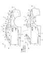
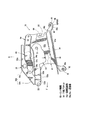
図2は後側開閉体としてのデッキカバーの支持構造を車幅方向内側から見た状態で示す側面図、図3はデッキカバーの車体に対する支持構造を車幅方向内側から見た状態で示す側面図、図4は自動車の後部車体構造において車両左側の構造を示す平面図、図5は図3の要部を拡大して示す側面図、図6は図4の要部を拡大して示す平面図である。
なお、図3中の符号131は車体後部の緩衝装置として車幅方向に延びるリヤバンパであるとともに図3中の符号133はトランクルーム4の後端を構成するリヤエンドパネルであり、いずれも車体後端部に位置する。
2 is a side view showing the support structure of the deck cover as the rear opening / closing body as seen from the inside in the vehicle width direction, and FIG. 3 is a side view showing the support structure of the deck cover with respect to the vehicle body as seen from the inside in the vehicle width direction. FIG. 4, FIG. 4 is a plan view showing the structure on the left side of the vehicle in the rear body structure of the automobile, FIG. 5 is an enlarged side view showing the main part of FIG. 3, and FIG. 6 is an enlarged plan view showing the main part of FIG. FIG.
3 is a rear bumper extending in the vehicle width direction as a shock absorber at the rear of the vehicle body, and 133 is a rear end panel constituting the rear end of the trunk room 4, both of which are rear end portions of the vehicle body. Located in.
図2に示すように、このデッキカバー10はアッパパネル10bとロアパネル10cとで骨組みを構成している。
また上述のデッキカバー10はその下部にデッキカバー支持ブラケット50(以下単にブラケット50と略記する)を備えている。
As shown in FIG. 2, the
Further, the above-described
さらに、リヤホイールハウス13の上部には、図3,図4に示すように、下部ブラケット14と上部ブラケット61とを取付けており、この上部ブラケット61には、車両前後方向に離間して2つの基端軸51,52を設け、これらの各基端軸51,52には平行リンクを構成するリンク53,54をそれぞれ取付けている。
Further, as shown in FIGS. 3 and 4, a
駆動側となる下側のリンク53の前端部は、ピン55を介してブラケット50の前下に枢支連結しており、従動側となる上側のリンク54の前端部は、ピン56を介してブラケット50の前後方向中間下部に枢支連結されている。
上述の基端軸51は開閉ルーフ1側の駆動ユニット12(図4参照)に備えた駆動モータとは別のデッキカバー10専用の駆動モータにより正逆駆動されるよう構成している。
The front end of the
The above-mentioned
そして、駆動モータの正転時には、平行リンクを構成する各リンク53,54が上昇方向(図2の時計方向)に回動し、ブラケット50を介してデッキカバー10を図2に仮想線βで示すように上方かつ後方に上昇駆動し、当該デッキカバー10を、センタールーフ1A,1Bおよびリヤルーフ1Cの開閉時に、これら各ルーフ1A,1B,1Cに対して非干渉位置に開放するものである。
When the drive motor rotates in the forward direction, the
要するに、後側開閉体としてのデッキカバー10は、当該デッキカバー10を支持する支持構造70としてブラケット50と、下部ブラケット14(取付けブラケット)と、上部ブラケット61(ベースブラケット)と四節のリンク機構60(リンク53,54を含む)とを備えている。ところで、リヤホイールハウス13は後輪を回転可能に覆うことができるように前後方向の中間位置が上方へ膨出した側面視アーチ形状に形成され、その頂部130(上端部)は、後突によるリヤホイールハウス13を含めた車体後部変形時にリヤバンパ131に対して上方に変形するため、該頂部130を上方変形部として形成している。
In short, the
上述のデッキカバー10の支持構造70は、該デッキカバー10をリヤホイールハウス13における頂部130(上方変位部)よりも前方部位に載置支持している。
The above-described
また、上述した各リンク53,54は、夫々の回動範囲のうち、それ以上ブラケット50が降下しない下限位置(反時計回り方向の限界回動位置)又はその近傍で、閉位置にあるデッキカバー10を支持する構造としている(図2、図3参照)。
In addition, each of the
これにより、後突による車体後部変形によって支持構造70がデッキカバー10を押し上げる際に、その押上げエネルギーがリンク53,54の反時計回りの回動によって吸収されない構成としたものである。
なお、上記の下限位置の近傍とは、目安として各リンク53,54の回動範囲に対して下限位置から10%以内の範囲を示すものとする。
Thus, when the
In addition, the vicinity of said lower limit position shall show the range within 10% from a lower limit position with respect to the rotation range of each
また、下部ブラケット14は、図5、図6に示すように、上部ブラケット61の台座であって、該上部ブラケット61の取付け座61aを載置支持可能に前下後高状に略水平に延びるベースプレート81と、該ベースプレート81の周縁であって前後方向および車幅方向に離間した各位置に取付孔82aを有する取付け部82とで一体に形成している。
5 and 6, the
ここで、図3、図4に示すように、上述のリヤホイールハウス13における下部ブラケット14に対応する位置には、リヤホイールハウス13の上面に沿ってプレート状のレインフォースメント132が設けられており、図3に示すように、上述の取付孔82aを有する取付け部82と、リヤホイールハウス13と、レインフォースメント132とをボルト、ナット等の締結部材91により締結固定している。
なお、図4、図6、図7の図面には、締結部材91は図示省略している。
Here, as shown in FIGS. 3 and 4, a plate-
4, 6, and 7, the
図3〜図6に示すように、複数の取付け部82のうち、下部ブラケット14の後端かつ車幅方向の内側に設けた取付け部82は、リヤホイールハウス13の上面に向けて延出した後側取付け脚部82Rとして形成している。この後側取付け脚部82Rは、図5、図6に示すように、ベースプレート81の後端から後下へ延出した延出部85と、該延出部85の後下端からレインフォースメント132の取付け箇所に当接可能に延出し、取付孔82aが貫通形成されたフランジ部86とで一体に形成している。
As shown in FIGS. 3 to 6, among the plurality of mounting
延出部85の基端部は、ベースプレート81と延出部85とで側面視ブリッジ(逆V字状)に屈曲した後側屈曲部14cを形成している。
The base end portion of the extending
後側取付け脚部82Rは、リヤホイールハウス13における頂部130に位置するように該リヤホイールハウス13の上面に取り付けている(図3、図4参照)。詳しくは、本実施例においては、後側取付け脚部82Rは、該後側取付け脚部82Rにおける後側屈曲部14cがリヤホイールハウス13における頂部130の鉛直上方位置(真上の位置)、すなわち頂部130と前後方向に一致する位置に取り付いている(図3中の仮想線で示したラインγ参照)。
The rear
また、図3〜図6に示すように、上部ブラケット61は下部に位置する取付け座61aと、この取付け座61aから上方に立上がる縦壁61bとを一体形成したもので、該縦壁61bの車幅方向内側に基端軸51,52を介して上述の各リンク53,54を取付ける一方、縦壁61bの車幅方向外側の面には、駆動側の基端側51を正逆駆動するモータおよびギヤから成る駆動ユニット62を取付けている。
As shown in FIGS. 3 to 6, the
さらに、縦壁61bの後端辺の上下方向の中間位置には、車体側に対して上部ブラケット61を仮止めする位置決め用の係止フック63が形成されている(図3、図5参照)。この係止フック63は、縦壁61bの後端辺から前方へ切欠き状に延び、さらに後端辺に沿って前上方向に延びるスリット状(溝状)に形成したものである。一方、車体側面の内壁における該中間位置に対応する部位には、係止フック63の縁部に係止可能に該部位から車幅方向内側へ突出するピン64が設けられている。
Further, a
係止フック63の溝形形成方向は、該係止フック63とピン64とが係止された状態から後突時にはピン64と係止フック63との係止が外れて上部ブラケット61が前傾姿勢になることを許容する方向に形成している。
The groove-forming direction of the locking
これにより、後突によりリヤホイールハウス13の山状に変形時に、係止フック63がピン64から抜けることを許容することで上部ブラケット61が車体側に対して仮固定された位置で踏ん張る(突張る)ことなく前傾し、リヤホイールハウス13の山状への変形を促進することができる。
As a result, when the
図3に示すように、上述のデッキカバー10を支持するブラケット50は、略水平なデッキカバー取付け部50aと、この取付け部50aの前端から前下に延びる延出部50bと、取付け部50aの前端に貫通形成された開口50c(いわゆる孔部)とを備えており、この開口50c上述の前下に延びる延出部50bとの両者により屈曲促進部50dを形成している。
As shown in FIG. 3, the
ここで、上述のデッキカバー10におけるブラケット50の取付け部50aと対応する位置には、図3に示すように、ロアパネル10cの上面に沿ってレインフォースメント10dを設けており、上述のデッキカバー取付け部50aと、ロアパネル10cと、レインフォースメント10dとを、ボルト、ナット等の締結部材15,15により共締め固定している。
Here, as shown in FIG. 3, a
また、上述の屈曲促進部50dは、周辺部位と比較して意図的に前後方向に脆弱にして変形を容易にした前後荷重脆弱部であって、後突による車体後部の変形時に、ブラケット50の車幅方向外側および上方への屈曲を促進するものである。
Further, the above-described
図5,図6に示すように、上述のリンク機構60のうちの下側のリンク53の前部には、前後方向に離間して屈曲ポイント53a,53bを形成し、後側の屈曲ポイント53aから前側の屈曲ポイント53bに向けて車幅方向外側前方に屈曲する屈曲部53cが一体形成されており、この屈曲部53cを、後突による車体後部の変形時に、当該リンク53の車幅方向外側への屈曲を促進する屈曲促進部と成している。
As shown in FIG. 5 and FIG. 6, bending
同様に、図5,図6に示すように、上述のリンク機構60のうちの上側のリンク54の前部には、前後方向に離間して屈曲ポイント54a,54bを形成し、後側の屈曲ポイント54aから前側の屈曲ポイント54bに向けて車幅方向外側前方に屈曲する屈曲部54cが一体形成されており、この屈曲部54cを、後突による車体後部の変形時に、当該リンク54の車幅方向外側への屈曲を促進する屈曲促進部と成している。
上述の各屈曲部53c,54cは、後側開閉体であるデッキカバー10と車体取付部である上部ブラケット61との前後相対変位を許容するものである。
Similarly, as shown in FIGS. 5 and 6, bending points 54 a and 54 b are formed in the front portion of the
Each of the
また、デッキカバー10の支持構造70は、上部ブラケット61を、リヤホイールハウス13の上面に沿って取り付けたレインフォースメント132に取り付けるのではなく、下部ブラケット14を介してレインフォースメント132に取り付けることで、リヤホイールハウス13における支持構造70の取付け箇所の周辺の補強と、荷重分散性と、支持構造70のリヤホイールハウス13に対する取付け性とを両立している。
The
ところで、図4に示すように、リンク53,54を備えたリンク機構60の前側には、他のリンクとしての前述の第1リンクF1および上下リンクR1と、車体剛性部材としてのシートバッククロスメンバ16(クロスバー部材と同意)とが設けられている。
Incidentally, as shown in FIG. 4, on the front side of the
上述のシートバッククロスメンバ16は、図示しないシートの背もたれ部であるシートバックの後方に位置するクロスバー部材であって、このシートバッククロスメンバ16は、車幅方向に延びる閉断面構造のクロスメンバ本体17と、このクロスメンバ本体17の左右両端部(但し、図4では車両左端部のみを示す)を車体に連結する連結部材18とを備えると共に、クロスメンバ本体17の左右両部は図示しないピラー部材を介してリヤフロアに連結されている。
The above-described seat
図4に示すように、上述のデッキカバー10のリンク機構60は、シートバッククロスメンバ16の後側に位置すると共に、このリンク機構60はシートバッククロスメンバ16における連結部材18と車幅方向にオーバラップするよう設けられている。一方で、上述の第1リンクF1および上下リンクR1は、連結部材18に対して車幅方向外側に位置しており、これにより車両デザイン要求を満足するよう構成している。
As shown in FIG. 4, the
図4に示すように、各リンクF1,R1を枢支したブラケット29の後部とボディサイド部28との間、並びに、各リンク53,54を有するリンク機構60の前部とボディサイド部28との間には、後突時における部材退避スペースS1が形成されている。
As shown in FIG. 4, between the rear part of the
このように構成したオープンカーVの後部車体構造の作用について説明する。
図3,図4に示す後突前のノーマルな状態から、車両後突により車体後部が変形すると、図8に示すようにリヤホイールハウス13が山状に変形し、当該リヤホイールハウス13の前後方向が圧縮される。
The operation of the rear body structure of the open car V configured as described above will be described.
3 and FIG. 4, when the rear part of the vehicle body is deformed by the rear collision of the vehicle from the normal state before the rear collision, the
ここで、本実施例においては、デッキカバー10は、リヤホイールハウス13における頂部130に対して前側部位に取り付けた支持構造70によって支持された構成としている。
Here, in the present embodiment, the
このため、後突によるリヤホイールハウス13の変形時にデッキカバー10は、上方に変位する力が加わるとともに、リヤホイールハウス13から支持構造70を介して前のめりになるようなモーメント、すなわちデッキカバー10後端が上方に変位するようなモーメントが加わることになり、車体後部へ侵入してくる衝突物を素早く回避することができる。
For this reason, when the
しかも下部ブラケット14の後端に設けた後側屈曲部14cをリヤホイールハウス13の頂部130近傍に配置することで、車両後突時に該後側屈曲部14cが屈曲起点となり、リヤホイールハウス13の頂部130がより一層上方に変形することを誘発する。
In addition, by arranging the rear
これにより、デッキカバー10は、該デッキカバー10後端が上方に変位するより大きなモーメントを、支持構造70を介してリヤホイールハウス13から受けることができ、衝突物をより素早く回避することができる。
As a result, the
また、デッキカバー10は上部ブラケット61の前のめり時に、支持構造70を介して後方から押圧されても、開閉ルーフ1や車幅方向の両側に設けたBピラー4,4等により、その前方移動が規制されているため、車室7に侵入することがなく、該車室7に対して上方や車幅方向外側へ変位する。
Further, even when the
このとき、支持構造70には、図7に示すように、屈曲部53c,54cが車幅方向外側へ屈曲したり、屈曲促進部50dが屈曲変形することで後突により山状に変形するリヤホイールハウス13に対してデッキカバー10が相対変位することを支持構造70によって許容することができる。
At this time, as shown in FIG. 7, the
従って、支持構造70における下側リンク53や上側リンク54が破断することがなく、各ピン55,56と各基端軸51,52とによるブラケット50と上部ブラケット61との連携を維持することができるため、重量物であるデッキカバー10は、車室7に向けて勢いよく前方へ変位しすぎることがなく、また支持構造70から分離することがなくしっかりと支持構造70に支持された状態を保つことができる。
Therefore, the
さらにまた、図7に示すように、各リンク53,54が車両前方かつ車幅方向外方へ屈曲変形しても、これら各リンク53,54の前部がシートバッククロスメンバ16と干渉することはなく、上記各リンク53,54の前部は部材退避スペースS1側に退避移動することになる。
Furthermore, as shown in FIG. 7, even if the
ここで、上述の各リンク53,54の前端部は、ピン55,56を介してブラケット50の上方へ屈曲しやすい屈曲促進部50dに連結されているので、この屈曲促進部50dの屈曲により、より一層荷重吸収を図ることができる。なお、図8においてはデッキカバー10が上動した状態を実線で示し、衝突前の状態を仮想線αで示している。
Here, since the front end portions of the
上述のブラケット50の屈曲促進部50dは前下に延びており、この延出構造により相対変位を許容する量(変位量)を増加させることができる。また、該屈曲促進部50dの基部には、通常時の剛性が確保できる範囲でサービスホール50cが形成されており、該サービスホール50c部に衝突荷重の応力を集中させることができるので、変形をコントロールすることができる。なお、サービスホール50cに代えてブラケット50の該当部を薄肉状となした低剛性部を形成してもよい。
The
また、上記リンク機構60の前方に他のリンクや車体剛性部材としてのシートバッククロスメンバ16が存在するが、その車幅方向外側に上述の部材退避スペースS1を設けたので、リンク機構60前部と他のリンクやシートバッククロスメンバ16との干渉を回避することができる。
Further, there is another link and a seat
なお、上述のデッキカバー10は車体に載置され、各リンク53,54による位置決め強度と、デッキカバー10それ自体の自重とで車体に当接支持されることが好ましく、これにより、デッキカバー10を円滑に上方に逃がして前後相対変位許容量を増加させることができる。
The
上述したオープンカーVの後部車体構造は、車室7よりも車体後部に開閉可能な後側開閉体としてのデッキカバー10が設けられ、後突による車体変形によって車体後端部としてのリヤバンパ131やリヤエンドパネル133に対して上方変位する上方変位部としての頂部130が車体後部に設けられ、該車体後部における、頂部130に対して鉛直上方位置(真上の位置)または前側位置、すなわち後突による車体変形時に上方変形する位置または前傾変形する位置においてデッキカバー10が車体後部から上方へ荷重伝達可能に支持されたものである(図3参照)。
The rear vehicle body structure of the open car V described above is provided with a
上記構成によれば、簡易な構成でデッキカバー10と衝突物との直接干渉を防止できる。
According to the above configuration, direct interference between the
詳述すると、上述したように、本実施例のオープンカーVの後部車体構造は、車体後部に備えたリヤホイールハウス13における頂部130に対して前側部位に取り付けた支持構造70によってデッキカバー10を支持する構成としている。すなわち、後突時の車体後部変形によって頂部130が上方変位するに伴って前傾変位する位置に取り付けた支持構造70によってデッキカバー10を支持する構成としている。
More specifically, as described above, the rear vehicle body structure of the open car V according to the present embodiment is such that the
これにより、デッキカバー10は、その後部が下がるような後のめりに変位することがなく、すなわち後方から車体に侵入してくる衝突物が存在する側へ変位することなく該デッキカバー10の後部を上方へ変位させることができる。
As a result, the
従って、デッキカバー10が該衝突物に直接干渉することを防止することができる。
Therefore, it is possible to prevent the
さらに、本実施例のオープンカーVの後部車体構造は、後突時に車体後部に侵入してきた衝突物とデッキカバー10とが直接干渉することを回避するために、例えば、デッキカバー10をより高い位置へ配置した構成のようにデッキカバー10を支持するリンク機構60を補強する必要がなく安定してデッキカバー10を支持することができる。加えて、車体重量が重量化したり配置スペースが嵩張ることもないため、簡素な構成でデッキカバー10が衝突物に直接干渉することを防止することができる。
Further, the rear vehicle body structure of the open car V according to the present embodiment has, for example, a
しかも、デッキカバー10を、後突と同時に衝突物と干渉しない位置まで駆動ユニット12に備えたモータの駆動によって素早く上昇させることなく、後突による車体後部変形を利用してデッキカバー10の後部を上方変位させる構成としたため、大型で高価な駆動ユニット12を備えることがなく簡素な構成によりデッキカバー10の衝突物との干渉を回避することができる。
In addition, the rear portion of the
この発明の態様として、上方変位部をリヤホイールハウス13の頂部130とし、デッキカバー10は、リヤホイールハウス13の頂部130よりも前方部位に支持されたものである(図3参照)。
As an aspect of the present invention, the upper displacement portion is the
ここで、リヤホイールハウス13の頂部130よりも前方部位は、後突時にリヤホイールハウス13の頂部130が上方変位することによって前傾変位する場所に相当する。上記構成によれば、デッキカバー10は、このようなリヤホイールハウス13の頂部130よりも前方部位に支持構造70を介して支持されるものである。このため、後突時にリヤホイールハウス13の頂部130が上方変位することによってデッキカバー10には、支持構造70を介して前傾するようなモーメント、すなわち、デッキカバー10の後端が上昇するようなモーメントを発生させることができ、後突により車体後方から侵入してくる衝突物に干渉することをより確実に回避することができる。
Here, the front part of the
またこの発明の態様として、デッキカバー10を支持する支持構造70には、該デッキカバー10を後部車体に開閉可能に支持するリンク機構60が設けられ、支持構造70の基部には、リヤホイールハウス13の頂部130が上方変位することを容易とする折曲げ促進部としての後側屈曲部14cを有するものである(図3〜図8参照)。
As an aspect of the present invention, the
上記構成によれば、後突時に上へ突の山状に変形するリヤホイールハウス13から上昇荷重を受けた支持構造70は、その基部に有する下部ブラケット14に設けた後側屈曲部14cが屈曲起点となることで該支持構造70がその配置場所で踏ん張ってリヤホイールハウス13の頂部130の上方変位を阻害することがなく、後突時に山状に変形するリヤホイールハウス13から受ける、デッキカバー10の上昇荷重を増加させることができる。
According to the above configuration, the
特に、本実施例では、後側屈曲部14cをリヤホイールハウス13の頂部130の鉛直上方に位置させたため、後突時にリヤホイールハウス13の頂部130の上方変形をさらに誘発することができる。
In particular, in the present embodiment, since the rear
またこの発明の態様として、デッキカバー10を支持する支持構造70には、該デッキカバー10を後部車体に開閉可能に支持するリンク機構60が設けられ、支持構造70には、屈曲変形容易部としての屈曲部53c,54cおよび屈曲促進部50dを有するものである(図5、図6参照)。
As an aspect of the present invention, the
上記構成によれば、デッキカバー10の前方変位や、衝突物との干渉による各リンク53,54の破断(意図しない折れ、割れ、せん断等)を抑制し、デッキカバー10を円滑に上昇させることができる。
According to the above configuration, the
詳述すると、後突時に後側屈曲部14cが曲げ変形することで支持構造70がデッキカバー10へ付与する荷重を吸収して山状に変形するリヤホイールハウス13に対するデッキカバー10の相対変位を許容することができる。
More specifically, the relative displacement of the
これにより、デッキカバー10が前方変位しすぎることを抑制することができるとともに、後突時にデッキカバー10が支持構造70から分離することなく、該デッキカバー10を円滑に上昇させることができる。
Accordingly, it is possible to suppress the
またこの発明の態様として、デッキカバー10を後部車体に開閉可能に支持するリンク機構60が設けられ、該リンク機構60は、閉止状態のデッキカバー10を、構造上の作動可能範囲の下限位置、または下限位置近傍で支持するものである(図2、図3参照)。
Further, as an aspect of the present invention, a
上記構成によれば、リンク機構60の作動可能範囲中間位置でのデッキカバー10の支持剛性に関係なく確実にデッキカバー10を上昇させて、後方からの衝突物を回避することができる。
According to the above configuration, it is possible to reliably raise the
この発明の構成と、上述の実施例との対応において、この発明の格納式ルーフ付き自動車は本実施例のオープンカーVに対応し、以下同様に、
後側開閉体はデッキカバー10に対応し、
上方屈曲容易部又はホイールハウスはリヤホイールハウス13に対応し、
車体後端部はリヤバンパ131又はリヤエンドパネル133に対応し、
リンク機構の基部は下部ブラケット14に対応し、
折曲げ促進部は後側屈曲部14cに対応し、
屈曲変形容易部は屈曲部53c,54cに対応するも、この発明は、上述の実施例の構成のみに限定されるものではない。
In the correspondence between the configuration of the present invention and the above-described embodiment, the retractable roof-equipped vehicle of the present invention corresponds to the open car V of the present embodiment, and so on.
The rear opening / closing body corresponds to the
The upward bendable part or wheel house corresponds to the
The rear end of the vehicle corresponds to the
The base of the link mechanism corresponds to the
The bending promoting portion corresponds to the
Although the easily deformable portion corresponds to the
例えば、本実施例のデッキカバー10は、車体後部に備えたリヤホイールハウス13における上方変位部としての頂部130よりも前側部位に取り付けた支持構造70を介して支持する構成としたが、この構成に限らず、リヤホイールハウス13における頂部130よりも後側部位でなければ、リヤホイールハウス13の頂部130の上方位置に取り付けた支持構造70を介して支持する構成であってもよい。
For example, the
また、上方変位部は、ホイールハウス13の頂部130に限らず、後突荷重を受けて前側に配置された部材に当接することで上方に突き上げられる部材など後突により上方変位する部位であれば特に限定しない。
Further, the upper displacement portion is not limited to the
例えば、後部車体側壁に沿って前後方向に延びるレインフォースメントを設け、これにリンク機構を取付ける場合には、上方屈曲容易部として、そのレインフォースメントを側面視で「へ」の字状に形成したり、下面にビードを設けたりするなど、後突時の変形による上方変位を促進する手段を設ければよい。 For example, when a reinforcement that extends in the front-rear direction along the rear vehicle body side wall is provided, and the link mechanism is attached to this, the reinforcement is formed in a letter-like shape in a side view as an easy-to-bend portion. It is sufficient to provide means for promoting upward displacement due to deformation at the time of rear collision, such as providing a bead on the lower surface.
また1つの頂部で「へ」の字状に変形させず、リンク機構の前後2点に上方に折れ曲がる頂部を発生させるようにして、リンク機構の取付け部位を台形状に上方変位させるようにしても良い。 In addition, the top of the link mechanism is not deformed into a “he” shape at one top, but a top that bends upward at two points before and after the link mechanism is generated, and the attachment part of the link mechanism is displaced upward in a trapezoidal shape. good.
さらにまた上記実施例においては後側開閉体としてデッキカバー10を例示したが、後側開閉体は車種によってはリヤルーフとしてもよい。また、リンクの前側に位置する車体剛性部材としては、シートバッククロスメンバ16に代えて、車室と荷室とを前後方向に仕切るバルクヘッドであってもよい。
Furthermore, in the above embodiment, the
以上説明したように、本発明は、例えば、車室よりも車体後部に、デッキカバー、後側ルーフ等の開閉可能な後側開閉体が設けられた格納式ルーフ付き自動車の後部車体構造について有用である。 As described above, the present invention is useful for, for example, a rear body structure of a vehicle with a retractable roof in which a rear opening and closing body such as a deck cover and a rear roof is provided at the rear of the vehicle body rather than the passenger compartment. It is.
7…車室
10…デッキカバー(後側開閉体)
131…リヤバンパ(車体後端部)
133…リヤエンドパネル(車体後端部)
130…ホイールハウスの頂部(上方変位部)
60…リンク機構
14…下部ブラケット(リンク機構の基部)
14c…後側屈曲部(折曲げ促進部)
53c,54c…屈曲部(屈曲変形容易部)
7.
131 ... Rear bumper (rear end of vehicle body)
133: Rear end panel (rear end of vehicle body)
130: Top of wheel house (upward displacement part)
60 ...
14c ... Rear bent part (folding promoting part)
53c, 54c ... bent portion (flexible deformation easy portion)
Claims (6)
後突による車体変形によって車体後端部に対して上方変位する上方変位部が前記車体後部に設けられ、
前記車体後部における、前記上方変位部に対して鉛直上方位置または前側位置に、前記後側開閉体が前記車体後部から上方へ荷重伝達可能に支持された
格納式ルーフ付き自動車の後部車体構造。 A rear opening / closing body that can be opened / closed at the rear of the vehicle body than the passenger compartment is provided,
An upper displacement portion that is displaced upward with respect to the rear end portion of the vehicle body by deformation of the vehicle body due to a rear collision is provided at the rear portion of the vehicle body,
A rear body structure of a vehicle with a retractable roof, wherein the rear opening / closing body is supported in a rearward direction of the vehicle body at a position vertically upward or a front side with respect to the upper displacement portion so that a load can be transmitted upward from the rear portion of the vehicle body.
前記後側開閉体は、前記上方屈曲容易部の頂部よりも前方部位に支持されたものである
請求項1に記載の格納式ルーフ付き自動車の後部車体構造。 The upper displacement part is a top part of the upward bendable part,
2. The rear body structure of a vehicle with a retractable roof according to claim 1, wherein the rear opening / closing body is supported at a front portion of a top portion of the upward bendable portion.
請求項1、または2に記載の格納式ルーフ付き自動車の後部車体構造。 The rear body structure of an automobile with a retractable roof according to claim 1 or 2, wherein the upper displacement portion is a top portion of a wheel house.
請求項1乃至3のいずれか1に記載の格納式ルーフ付き自動車の後部車体構造。 A link mechanism that supports the rear opening / closing body so as to be openable / closable to the rear vehicle body is provided, and a bending promoting portion that facilitates upward displacement of the upper displacement portion is provided at a base portion of the link mechanism. 4. A rear body structure of a car with a retractable roof according to any one of 1 to 3.
請求項1乃至4のいずれか1項に記載の格納式ルーフ付き自動車の後部車体構造。 5. The link mechanism for supporting the rear opening / closing body on the rear vehicle body so as to be openable / closable is provided, and the link mechanism has an easily bending deformation portion with respect to a longitudinal load. Rear body structure of a car with retractable roof.
請求項1乃至5のいずれか1項に記載の格納式ルーフ付き自動車の後部車体構造。 There is provided a link mechanism that supports the rear opening / closing body to be openable / closable on the rear vehicle body, and the link mechanism connects the rear opening / closing body in a closed state to a lower limit position of a structural operable range or near a lower limit position. The rear body structure of an automobile with a retractable roof according to any one of claims 1 to 5, wherein the rear body structure is supported by the vehicle.
Priority Applications (4)
| Application Number | Priority Date | Filing Date | Title |
|---|---|---|---|
| JP2016054762A JP6315012B2 (en) | 2016-03-18 | 2016-03-18 | Rear body structure of a car with retractable roof |
| US15/454,347 US9963024B2 (en) | 2016-03-18 | 2017-03-09 | Rear vehicle-body structure of automotive vehicle with storing-type roof |
| CN201710146077.3A CN107199861B (en) | 2016-03-18 | 2017-03-13 | Rear body structure of automobile with storage type ceiling |
| DE102017002481.2A DE102017002481B4 (en) | 2016-03-18 | 2017-03-14 | Rear vehicle body structure of a motor vehicle with a storage-type roof and method for absorbing a rear-end impact |
Applications Claiming Priority (1)
| Application Number | Priority Date | Filing Date | Title |
|---|---|---|---|
| JP2016054762A JP6315012B2 (en) | 2016-03-18 | 2016-03-18 | Rear body structure of a car with retractable roof |
Publications (2)
| Publication Number | Publication Date |
|---|---|
| JP2017165352A true JP2017165352A (en) | 2017-09-21 |
| JP6315012B2 JP6315012B2 (en) | 2018-04-25 |
Family
ID=59751536
Family Applications (1)
| Application Number | Title | Priority Date | Filing Date |
|---|---|---|---|
| JP2016054762A Active JP6315012B2 (en) | 2016-03-18 | 2016-03-18 | Rear body structure of a car with retractable roof |
Country Status (4)
| Country | Link |
|---|---|
| US (1) | US9963024B2 (en) |
| JP (1) | JP6315012B2 (en) |
| CN (1) | CN107199861B (en) |
| DE (1) | DE102017002481B4 (en) |
Families Citing this family (1)
| Publication number | Priority date | Publication date | Assignee | Title |
|---|---|---|---|---|
| JP6315012B2 (en) * | 2016-03-18 | 2018-04-25 | マツダ株式会社 | Rear body structure of a car with retractable roof |
Citations (10)
| Publication number | Priority date | Publication date | Assignee | Title |
|---|---|---|---|---|
| JPH0282624U (en) * | 1988-12-16 | 1990-06-26 | ||
| JPH05213068A (en) * | 1992-02-06 | 1993-08-24 | Honda Motor Co Ltd | Storage roof fixing device for open roof type automobile |
| JPH07195944A (en) * | 1993-10-23 | 1995-08-01 | Dr Ing H C F Porsche Ag | Controls for car hoods and hood box lids |
| JPH09104234A (en) * | 1995-09-04 | 1997-04-22 | Dr Ing H C F Porsche Ag | Vehicle hood |
| JP2001239838A (en) * | 2000-01-18 | 2001-09-04 | Webasto Vehicle Systems Internatl Gmbh | Convertible vehicle roof |
| JP2006321278A (en) * | 2005-05-17 | 2006-11-30 | Mazda Motor Corp | Rear body structure |
| JP2012101770A (en) * | 2010-11-15 | 2012-05-31 | Mazda Motor Corp | Rear body structure of vehicle |
| US20160031306A1 (en) * | 2014-07-30 | 2016-02-04 | Dr. Ing. H.C. F. Porsche Aktiengesellschaft | Arrangement of a cover of a folding-top compartment in a cabriolet |
| JP2016117459A (en) * | 2014-12-24 | 2016-06-30 | マツダ株式会社 | Deck cover support structure of motor vehicle |
| JP2016150587A (en) * | 2015-02-16 | 2016-08-22 | マツダ株式会社 | Rear part body structure of vehicle |
Family Cites Families (18)
| Publication number | Priority date | Publication date | Assignee | Title |
|---|---|---|---|---|
| US6217104B1 (en) * | 1999-06-16 | 2001-04-17 | Cts Fahrzeug Dachsysteme Gmbh | Retractable hard top module |
| JP3594912B2 (en) | 2001-06-29 | 2004-12-02 | 高田工業株式会社 | Folding roof opening and closing device for vehicles |
| US7246841B2 (en) * | 2004-09-23 | 2007-07-24 | Asc Incorporated | In-folding convertible roof |
| JP5245610B2 (en) * | 2008-07-28 | 2013-07-24 | アイシン精機株式会社 | Panel moving device |
| DE112010000832T5 (en) * | 2009-01-08 | 2012-09-13 | Fisker Automotive, Inc. | Hinged hood |
| US7819459B2 (en) * | 2009-02-11 | 2010-10-26 | Valmet Automotive Oy | Convertible vehicle |
| US20110095575A1 (en) * | 2009-10-22 | 2011-04-28 | Mazda Motor Corporation | Movable roof structure of vehicle |
| DE102009050497A1 (en) * | 2009-10-23 | 2011-04-28 | Dr. Ing. H.C. F. Porsche Aktiengesellschaft | Device for locking and unlocking a top compartment lid |
| DE102011010842A1 (en) * | 2011-02-10 | 2012-02-02 | Daimler Ag | Convertible soft top for open passenger car, has roof part forming front region of top in closed position and partially transparent, where top is partially accommodatable in storage space in open position |
| DE102012005509A1 (en) * | 2012-03-17 | 2012-11-15 | Daimler Ag | Method for mounting flap element to corresponding pivot part of motor vehicle, involves positioning rule part of setting gauge relative to component and another rule part of setting gauge relative to pivot part |
| ITBO20130137A1 (en) * | 2013-03-29 | 2014-09-30 | Ferrari Spa | CAR WITH RIGID OPENING ROOF, PREFERABLY WITH FOUR PLACES |
| DE102015010338B4 (en) * | 2014-09-26 | 2018-10-31 | Mazda Motor Corporation | Rear vehicle body structure of a vehicle |
| JP6308086B2 (en) * | 2014-09-26 | 2018-04-11 | マツダ株式会社 | Rear body structure of the vehicle |
| DE102015016630B4 (en) * | 2014-12-24 | 2019-05-29 | Mazda Motor Corporation | Structure of a rear portion of a vehicle body for a motor vehicle |
| JP6323429B2 (en) * | 2015-10-29 | 2018-05-16 | マツダ株式会社 | Rear structure of the vehicle |
| JP6586383B2 (en) * | 2016-03-18 | 2019-10-02 | マツダ株式会社 | Automobile roof structure |
| JP6677543B2 (en) * | 2016-03-18 | 2020-04-08 | マツダ株式会社 | Automobile body structure with retractable roof |
| JP6315012B2 (en) * | 2016-03-18 | 2018-04-25 | マツダ株式会社 | Rear body structure of a car with retractable roof |
-
2016
- 2016-03-18 JP JP2016054762A patent/JP6315012B2/en active Active
-
2017
- 2017-03-09 US US15/454,347 patent/US9963024B2/en active Active
- 2017-03-13 CN CN201710146077.3A patent/CN107199861B/en active Active
- 2017-03-14 DE DE102017002481.2A patent/DE102017002481B4/en active Active
Patent Citations (10)
| Publication number | Priority date | Publication date | Assignee | Title |
|---|---|---|---|---|
| JPH0282624U (en) * | 1988-12-16 | 1990-06-26 | ||
| JPH05213068A (en) * | 1992-02-06 | 1993-08-24 | Honda Motor Co Ltd | Storage roof fixing device for open roof type automobile |
| JPH07195944A (en) * | 1993-10-23 | 1995-08-01 | Dr Ing H C F Porsche Ag | Controls for car hoods and hood box lids |
| JPH09104234A (en) * | 1995-09-04 | 1997-04-22 | Dr Ing H C F Porsche Ag | Vehicle hood |
| JP2001239838A (en) * | 2000-01-18 | 2001-09-04 | Webasto Vehicle Systems Internatl Gmbh | Convertible vehicle roof |
| JP2006321278A (en) * | 2005-05-17 | 2006-11-30 | Mazda Motor Corp | Rear body structure |
| JP2012101770A (en) * | 2010-11-15 | 2012-05-31 | Mazda Motor Corp | Rear body structure of vehicle |
| US20160031306A1 (en) * | 2014-07-30 | 2016-02-04 | Dr. Ing. H.C. F. Porsche Aktiengesellschaft | Arrangement of a cover of a folding-top compartment in a cabriolet |
| JP2016117459A (en) * | 2014-12-24 | 2016-06-30 | マツダ株式会社 | Deck cover support structure of motor vehicle |
| JP2016150587A (en) * | 2015-02-16 | 2016-08-22 | マツダ株式会社 | Rear part body structure of vehicle |
Also Published As
| Publication number | Publication date |
|---|---|
| DE102017002481B4 (en) | 2025-12-11 |
| CN107199861A (en) | 2017-09-26 |
| US20170267083A1 (en) | 2017-09-21 |
| DE102017002481A1 (en) | 2017-09-21 |
| US9963024B2 (en) | 2018-05-08 |
| JP6315012B2 (en) | 2018-04-25 |
| CN107199861B (en) | 2020-01-14 |
Similar Documents
| Publication | Publication Date | Title |
|---|---|---|
| JP5471559B2 (en) | Automobile undercarriage | |
| JP5769092B2 (en) | Power supply protection frame structure | |
| US8167360B2 (en) | Vehicle cross member assembly with tunnel bracket | |
| CN103987615A (en) | car body front structure | |
| JP6131967B2 (en) | Auto body structure | |
| JP2014034226A (en) | Vehicle seat | |
| JP4556674B2 (en) | Vehicle side body structure | |
| JP6082234B2 (en) | Steering column support structure | |
| JP6315012B2 (en) | Rear body structure of a car with retractable roof | |
| JP5852623B2 (en) | Body structure | |
| JP5494429B2 (en) | Rear body structure of the vehicle | |
| JP2010163113A (en) | Rear part vehicle body structure for vehicle | |
| JP2010163112A (en) | Roof opening and closing structure for vehicle | |
| JP2007145129A (en) | Body front structure | |
| JP4290016B2 (en) | Slope device for vehicle | |
| JP2007261481A (en) | Vehicle side body structure | |
| JP5035836B2 (en) | Cab | |
| JP2010167872A (en) | Vehicular seatbelt arranging structure | |
| JP4507871B2 (en) | Open car rear body structure | |
| JP2000211547A (en) | Body structure of one box car with chassis frame | |
| JP6197903B2 (en) | Rear body structure of a car with retractable roof | |
| JP2015193342A (en) | Vehicle floor structure | |
| JP6893385B2 (en) | Vehicle front structure | |
| JP2008006899A (en) | Center hinge structure of split retractable seat back | |
| JP6052310B2 (en) | Auto body structure |
Legal Events
| Date | Code | Title | Description |
|---|---|---|---|
| A977 | Report on retrieval |
Free format text: JAPANESE INTERMEDIATE CODE: A971007 Effective date: 20170707 |
|
| A131 | Notification of reasons for refusal |
Free format text: JAPANESE INTERMEDIATE CODE: A131 Effective date: 20170725 |
|
| A521 | Request for written amendment filed |
Free format text: JAPANESE INTERMEDIATE CODE: A523 Effective date: 20170921 |
|
| TRDD | Decision of grant or rejection written | ||
| A01 | Written decision to grant a patent or to grant a registration (utility model) |
Free format text: JAPANESE INTERMEDIATE CODE: A01 Effective date: 20180227 |
|
| A61 | First payment of annual fees (during grant procedure) |
Free format text: JAPANESE INTERMEDIATE CODE: A61 Effective date: 20180312 |
|
| R150 | Certificate of patent or registration of utility model |
Ref document number: 6315012 Country of ref document: JP Free format text: JAPANESE INTERMEDIATE CODE: R150 |