JP2017166366A - Scroll compressor - Google Patents
Scroll compressor Download PDFInfo
- Publication number
- JP2017166366A JP2017166366A JP2016050888A JP2016050888A JP2017166366A JP 2017166366 A JP2017166366 A JP 2017166366A JP 2016050888 A JP2016050888 A JP 2016050888A JP 2016050888 A JP2016050888 A JP 2016050888A JP 2017166366 A JP2017166366 A JP 2017166366A
- Authority
- JP
- Japan
- Prior art keywords
- scroll
- back pressure
- pressure chamber
- compression mechanism
- compression
- Prior art date
- Legal status (The legal status is an assumption and is not a legal conclusion. Google has not performed a legal analysis and makes no representation as to the accuracy of the status listed.)
- Granted
Links
Images






Classifications
-
- F—MECHANICAL ENGINEERING; LIGHTING; HEATING; WEAPONS; BLASTING
- F04—POSITIVE - DISPLACEMENT MACHINES FOR LIQUIDS; PUMPS FOR LIQUIDS OR ELASTIC FLUIDS
- F04C—ROTARY-PISTON, OR OSCILLATING-PISTON, POSITIVE-DISPLACEMENT MACHINES FOR LIQUIDS; ROTARY-PISTON, OR OSCILLATING-PISTON, POSITIVE-DISPLACEMENT PUMPS
- F04C18/00—Rotary-piston pumps specially adapted for elastic fluids
- F04C18/02—Rotary-piston pumps specially adapted for elastic fluids of arcuate-engagement type, i.e. with circular translatory movement of co-operating members, each member having the same number of teeth or tooth-equivalents
-
- F—MECHANICAL ENGINEERING; LIGHTING; HEATING; WEAPONS; BLASTING
- F04—POSITIVE - DISPLACEMENT MACHINES FOR LIQUIDS; PUMPS FOR LIQUIDS OR ELASTIC FLUIDS
- F04C—ROTARY-PISTON, OR OSCILLATING-PISTON, POSITIVE-DISPLACEMENT MACHINES FOR LIQUIDS; ROTARY-PISTON, OR OSCILLATING-PISTON, POSITIVE-DISPLACEMENT PUMPS
- F04C18/00—Rotary-piston pumps specially adapted for elastic fluids
- F04C18/02—Rotary-piston pumps specially adapted for elastic fluids of arcuate-engagement type, i.e. with circular translatory movement of co-operating members, each member having the same number of teeth or tooth-equivalents
- F04C18/0207—Rotary-piston pumps specially adapted for elastic fluids of arcuate-engagement type, i.e. with circular translatory movement of co-operating members, each member having the same number of teeth or tooth-equivalents both members having co-operating elements in spiral form
- F04C18/0215—Rotary-piston pumps specially adapted for elastic fluids of arcuate-engagement type, i.e. with circular translatory movement of co-operating members, each member having the same number of teeth or tooth-equivalents both members having co-operating elements in spiral form where only one member is moving
-
- F—MECHANICAL ENGINEERING; LIGHTING; HEATING; WEAPONS; BLASTING
- F04—POSITIVE - DISPLACEMENT MACHINES FOR LIQUIDS; PUMPS FOR LIQUIDS OR ELASTIC FLUIDS
- F04C—ROTARY-PISTON, OR OSCILLATING-PISTON, POSITIVE-DISPLACEMENT MACHINES FOR LIQUIDS; ROTARY-PISTON, OR OSCILLATING-PISTON, POSITIVE-DISPLACEMENT PUMPS
- F04C18/00—Rotary-piston pumps specially adapted for elastic fluids
- F04C18/02—Rotary-piston pumps specially adapted for elastic fluids of arcuate-engagement type, i.e. with circular translatory movement of co-operating members, each member having the same number of teeth or tooth-equivalents
- F04C18/0207—Rotary-piston pumps specially adapted for elastic fluids of arcuate-engagement type, i.e. with circular translatory movement of co-operating members, each member having the same number of teeth or tooth-equivalents both members having co-operating elements in spiral form
- F04C18/0246—Details concerning the involute wraps or their base, e.g. geometry
- F04C18/0269—Details concerning the involute wraps
- F04C18/0276—Different wall heights
-
- F—MECHANICAL ENGINEERING; LIGHTING; HEATING; WEAPONS; BLASTING
- F04—POSITIVE - DISPLACEMENT MACHINES FOR LIQUIDS; PUMPS FOR LIQUIDS OR ELASTIC FLUIDS
- F04C—ROTARY-PISTON, OR OSCILLATING-PISTON, POSITIVE-DISPLACEMENT MACHINES FOR LIQUIDS; ROTARY-PISTON, OR OSCILLATING-PISTON, POSITIVE-DISPLACEMENT PUMPS
- F04C23/00—Combinations of two or more pumps, each being of rotary-piston or oscillating-piston type, specially adapted for elastic fluids; Pumping installations specially adapted for elastic fluids; Multi-stage pumps specially adapted for elastic fluids
- F04C23/008—Hermetic pumps
-
- F—MECHANICAL ENGINEERING; LIGHTING; HEATING; WEAPONS; BLASTING
- F04—POSITIVE - DISPLACEMENT MACHINES FOR LIQUIDS; PUMPS FOR LIQUIDS OR ELASTIC FLUIDS
- F04C—ROTARY-PISTON, OR OSCILLATING-PISTON, POSITIVE-DISPLACEMENT MACHINES FOR LIQUIDS; ROTARY-PISTON, OR OSCILLATING-PISTON, POSITIVE-DISPLACEMENT PUMPS
- F04C27/00—Sealing arrangements in rotary-piston pumps specially adapted for elastic fluids
- F04C27/005—Axial sealings for working fluid
-
- F—MECHANICAL ENGINEERING; LIGHTING; HEATING; WEAPONS; BLASTING
- F04—POSITIVE - DISPLACEMENT MACHINES FOR LIQUIDS; PUMPS FOR LIQUIDS OR ELASTIC FLUIDS
- F04C—ROTARY-PISTON, OR OSCILLATING-PISTON, POSITIVE-DISPLACEMENT MACHINES FOR LIQUIDS; ROTARY-PISTON, OR OSCILLATING-PISTON, POSITIVE-DISPLACEMENT PUMPS
- F04C29/00—Component parts, details or accessories of pumps or pumping installations, not provided for in groups F04C18/00 - F04C28/00
- F04C29/02—Lubrication; Lubricant separation
- F04C29/028—Means for improving or restricting lubricant flow
Landscapes
- Engineering & Computer Science (AREA)
- Mechanical Engineering (AREA)
- General Engineering & Computer Science (AREA)
- Rotary Pumps (AREA)
- Applications Or Details Of Rotary Compressors (AREA)
Abstract
Description
本発明は、固定スクロールに対して可動スクロールを公転旋回運動させることにより、両スクロールのラップ間に形成された圧縮室で作動流体を圧縮するスクロール圧縮機に関する。 The present invention relates to a scroll compressor that compresses a working fluid in a compression chamber formed between laps of both scrolls by orbiting a movable scroll with respect to a fixed scroll.
従来よりこの種スクロール圧縮機は、鏡板の表面に渦巻き状のラップを備えた固定スクロールと、鏡板の表面に渦巻き状のラップを備えた可動スクロールから成る圧縮機構を備え、各スクロールのラップを対向させてラップ間に圧縮室を形成し、モータにより固定スクロールに対して可動スクロールを公転旋回運動させることにより、圧縮室で作動流体(冷媒)を圧縮するように構成されている(例えば、特許文献1参照)。 Conventionally, this type of scroll compressor has a compression mechanism composed of a fixed scroll having a spiral wrap on the surface of the end plate and a movable scroll having a spiral wrap on the surface of the end plate, and each scroll wrap is opposed to each other. The compression chamber is formed between the wraps, and the movable fluid is revolved with respect to the fixed scroll by a motor, and the working fluid (refrigerant) is compressed in the compression chamber (for example, Patent Documents). 1).
この場合、可動スクロールの鏡板の背面には、圧縮室からの圧縮反力に対向して可動スクロールを固定スクロールに押し付けるための背圧室が形成されている。従来ではこの背圧室に吐出圧を調整した後に供給し、且つ、背圧室の圧力を一定に維持することにより、圧縮反力に打ち勝つ一定の背圧荷重を可動スクロールに付加していた。また、特許文献1では圧縮最終工程(設計吐出終了工程)の近傍で吸入側と背圧室とを連通するバランス穴を形成し、このバランス穴により各摺動部分に強制給油する構成としていた。
In this case, a back pressure chamber for pressing the movable scroll against the fixed scroll is formed on the back surface of the end plate of the movable scroll so as to oppose the compression reaction force from the compression chamber. Conventionally, a constant back pressure load that overcomes the compression reaction force is applied to the movable scroll by supplying the back pressure chamber after adjusting the discharge pressure and maintaining the pressure in the back pressure chamber constant. Moreover, in
ここで、圧縮反力は可動スクロールの公転旋回運動の一回転中で大きく変動する。そして、背圧荷重は従来ではこの変動する圧縮反力が最大となる値より大きくなるように設定されていた。そのため、圧縮反力が小さくなる旋回角度では、固定スクロールに可動スクロールに押し付ける力が過剰となり、各ラップとそれが押し付けられる鏡板との摩擦力が大きくなって、消費動力が増大する問題がある。 Here, the compression reaction force largely fluctuates during one revolution of the orbiting scroll. Conventionally, the back pressure load is set to be larger than a value at which the fluctuating compression reaction force becomes maximum. Therefore, at the turning angle at which the compression reaction force becomes small, the force pressing the movable scroll against the fixed scroll becomes excessive, and the frictional force between each lap and the end plate against which the lap is pressed increases, resulting in a problem that the power consumption increases.
この圧縮反力は理論的には前述した吐出終了工程で最小となる。そこで、例えば特許文献1のように設計吐出終了工程(圧縮最終工程)の近傍で吸入側と背圧室とをバランス穴で連通することも考えられる。
The compression reaction force is theoretically minimized in the above-described discharge end process. Therefore, for example, it is conceivable to connect the suction side and the back pressure chamber through a balance hole in the vicinity of the designed discharge end process (compression final process) as in
しかしながら、設計吐出終了工程が過ぎても、ラップ間はオイルによってシールされているので、圧縮反力は設計吐出終了工程よりも遅れて低下することになる。そのため、従来の如く設計吐出終了工程で吸入側と背圧室とを連通してしまうと、押し付ける力が不足し、最悪の場合には背圧荷重が圧縮反力より小さくなって、両スクロールが離れてしまい、圧縮不良を引き起こすと云う問題があった。 However, even after the design discharge end process, the lap is sealed with oil, so that the compression reaction force falls later than the design discharge end process. Therefore, if the suction side communicates with the back pressure chamber in the design discharge end process as in the conventional case, the pressing force is insufficient, and in the worst case, the back pressure load becomes smaller than the compression reaction force, and both scrolls are There was a problem that it was separated and caused a compression failure.
本発明は、係る従来の技術的課題を解決するために成されたものであり、圧縮不良を引き起こすこと無く、両スクロール間の摩擦力を低減することができるスクロール圧縮機を提供することを目的とする。 The present invention has been made to solve the conventional technical problem, and an object of the present invention is to provide a scroll compressor capable of reducing the frictional force between both scrolls without causing a compression failure. And
上記課題を解決するために、本発明のスクロール圧縮機は、各鏡板の各表面にそれぞれ渦巻き状のラップが対向して形成された固定スクロール及び可動スクロールから成る圧縮機構を備え、可動スクロールを固定スクロールに対して公転旋回運動させることにより、両スクロールの各ラップ間に形成された圧縮室で作動流体を圧縮するものであって、可動スクロールの鏡板の背面に形成された背圧室と、公転旋回運動する可動スクロールにより開閉され、背圧室と吸入圧領域とを連通するための連通部を備え、この連通部は、圧縮機構の設計吐出終了工程より所定の旋回角度だけ遅れた角度において背圧室と吸入圧領域とを連通することを特徴とする。 In order to solve the above problems, a scroll compressor according to the present invention includes a compression mechanism including a fixed scroll and a movable scroll each having a spiral wrap formed on each surface of each end plate so as to face each other, and the movable scroll is fixed. By rotating orbiting the scroll, the working fluid is compressed in the compression chamber formed between the laps of both scrolls, and the back pressure chamber formed on the back surface of the end plate of the movable scroll and the revolution It is opened and closed by an orbiting scroll that has a turning motion, and has a communication part for communicating the back pressure chamber and the suction pressure region. This communication part has a back at an angle delayed by a predetermined turning angle from the design discharge end process of the compression mechanism. The pressure chamber communicates with the suction pressure region.
請求項2の発明のスクロール圧縮機は、上記発明において連通部は、圧縮機構の設計吐出終了工程の旋回角度より、各ラップ間がオイルシールされている範囲だけ遅れた角度において背圧室と吸入圧領域とを連通することを特徴とする。 In the scroll compressor according to a second aspect of the present invention, in the above invention, the communication portion is connected to the back pressure chamber and the suction at an angle that is delayed from the turning angle in the design discharge end process of the compression mechanism by a range in which each lap is oil sealed. It is characterized by communicating with the pressure region.
請求項3の発明のスクロール圧縮機は、上記発明において連通部は、圧縮機構の設計吐出終了工程の旋回角度より、各ラップ間がオイルシールされている範囲だけ遅れた角度を中心とした所定の旋回角度の範囲に複数形成されていることを特徴とする。 According to a third aspect of the present invention, there is provided the scroll compressor according to the above invention, wherein the communicating portion has a predetermined centered on an angle delayed by a range in which each lap is oil-sealed from the turning angle in the design discharge end process of the compression mechanism. A plurality of swivel angles are formed.
請求項4の発明のスクロール圧縮機は、上記各発明において可動スクロールの鏡板の背面に接触して背圧室と吸入圧領域とを区画するスラストプレートを備え、連通部は、スラストプレートに形成されていることを特徴とする。 According to a fourth aspect of the present invention, there is provided a scroll compressor comprising a thrust plate that contacts the back surface of the end plate of the movable scroll in each of the above inventions to partition the back pressure chamber and the suction pressure region, and the communication portion is formed on the thrust plate. It is characterized by.
請求項5の発明のスクロール圧縮機は、上記各発明において連通部を、背圧室と吸入圧領域とに開口した孔にて構成したことを特徴とする。 A scroll compressor according to a fifth aspect of the present invention is characterized in that, in each of the above-described inventions, the communicating portion is configured by a hole opened to the back pressure chamber and the suction pressure region.
請求項6の発明のスクロール圧縮機は、請求項1乃至請求項4の発明において連通部を、背圧室から吸入圧領域に渡る溝にて構成したことを特徴とする。 A scroll compressor according to a sixth aspect of the invention is characterized in that, in the first to fourth aspects of the invention, the communicating portion is formed by a groove extending from the back pressure chamber to the suction pressure region.
本発明によれば、各鏡板の各表面にそれぞれ渦巻き状のラップが対向して形成された固定スクロール及び可動スクロールから成る圧縮機構を備え、可動スクロールを固定スクロールに対して公転旋回運動させることにより、両スクロールの各ラップ間に形成された圧縮室で作動流体を圧縮するスクロール圧縮機において、可動スクロールの鏡板の背面に形成された背圧室と、公転旋回運動する可動スクロールにより開閉され、背圧室と吸入圧領域とを連通するための連通部を備えており、この連通部が、圧縮機構の設計吐出終了工程より所定の旋回角度だけ遅れた角度において背圧室と吸入圧領域とを連通するようにしたので、可動スクロールの公転旋回運動の一回転中で大きく変動する圧縮反力が低下する適切な角度にて背圧室からの背圧荷重を低下させることができるようになる。 According to the present invention, a compression mechanism including a fixed scroll and a movable scroll each having a spiral wrap formed on each surface of each end plate is opposed to each other, and the movable scroll is revolved with respect to the fixed scroll. In the scroll compressor that compresses the working fluid in the compression chamber formed between the laps of both scrolls, the back pressure chamber formed on the back surface of the end plate of the movable scroll and the movable scroll that revolves and revolves. A communication portion for communicating the pressure chamber and the suction pressure region is provided, and this communication portion connects the back pressure chamber and the suction pressure region at an angle delayed by a predetermined turning angle from the design discharge end process of the compression mechanism. Because it is in communication, the back pressure from the back pressure chamber is at an appropriate angle at which the compression reaction force, which fluctuates greatly during one revolution of the orbiting scroll, is reduced. So heavy can be reduced.
これにより、圧縮機構において圧縮不良を引き起こすこと無く、両スクロール間の摩擦力を低減して、消費動力の増大を解消することができるようになる。 As a result, the frictional force between the scrolls can be reduced and the increase in power consumption can be eliminated without causing a compression failure in the compression mechanism.
特に、請求項2の発明の如く連通部が、圧縮機構の設計吐出終了工程の旋回角度より、各ラップ間がオイルシールされている範囲だけ遅れた角度において背圧室と吸入圧領域とを連通するようにすれば、設計吐出終了工程の後も、オイルで各ラップ間がシールされることによる圧縮反力の低下の遅れに合わせて的確に背圧荷重を低下させることができるようになる。 In particular, as in the second aspect of the present invention, the communicating portion communicates the back pressure chamber and the suction pressure region at an angle that is delayed from the swivel angle in the design discharge end process of the compression mechanism by a range in which each lap is oil-sealed. By doing so, it is possible to accurately reduce the back pressure load in accordance with the delay in the reduction of the compression reaction force due to the sealing between the laps with oil even after the design discharge end process.
更に、請求項3の発明の如く連通部を、圧縮機構の設計吐出終了工程の旋回角度より、各ラップ間がオイルシールされている範囲だけ遅れた角度を中心とした所定の旋回角度の範囲に複数形成するようにすれば、圧縮反力の低下に沿って背圧荷重を低下させることが可能となり、両スクロール間の摩擦力をより一層好適に低減することができるようになるものである。 Further, as in the third aspect of the present invention, the communication portion is set within a predetermined swivel angle range centered on an angle that is delayed by a range in which each lap is oil-sealed from the swivel angle in the design discharge end process of the compression mechanism. If a plurality of them are formed, the back pressure load can be reduced along with the reduction of the compression reaction force, and the frictional force between the two scrolls can be more suitably reduced.
この場合、請求項4の発明の如く可動スクロールの鏡板の背面に接触して背圧室と吸入圧領域とを区画するスラストプレートを備えるとき、このスラストプレートに連通部を形成すようにすれば、圧縮機を構成するハウジング等に直接形成する場合に比して、生産性が極めて良好となる。
In this case, when a thrust plate that contacts the rear surface of the end plate of the movable scroll and separates the back pressure chamber and the suction pressure region is provided as in the invention of
また、請求項5の発明の如く背圧室と吸入圧領域とに開口した孔にて連通部を構成すれば、加工性も良好と成る。これは、請求項6の発明の如く背圧室から吸入圧領域に渡る溝にて連通部を構成した場合にも同様である。 Further, if the communicating portion is constituted by a hole opened in the back pressure chamber and the suction pressure region as in the invention of claim 5, the workability is improved. The same applies to the case where the communicating portion is constituted by a groove extending from the back pressure chamber to the suction pressure region as in the sixth aspect of the invention.
以下、本発明の実施の形態について、図面に基づき詳細に説明する。 Hereinafter, embodiments of the present invention will be described in detail with reference to the drawings.
図1は本発明を適用した一実施形態のスクロール圧縮機1の断面図である。実施例のスクロール圧縮機1は、例えば車両用空気調和装置の冷媒回路に使用され、車両用空気調和装置の作動流体としての冷媒を吸入し、圧縮して吐出するものであり、電動モータ2と、この電動モータ2を運転するためのインバータ3と、電動モータ2によって駆動される圧縮機構4とを備えた所謂インバータ一体型のスクロール圧縮機である。
FIG. 1 is a cross-sectional view of a
実施例のスクロール圧縮機1は、電動モータ2及びインバータ3をその内側に収容するメインハウジング6と、圧縮機構4をその内側に収容する圧縮機構ハウジング7と、インバータカバー8と、圧縮機構カバー9を備えている。そして、これらメインハウジング6と、圧縮機構ハウジング7とインバータカバー8と圧縮機構カバー9は何れも金属製(実施例ではアルミニウム製)であり、それらが一体的に接合されてスクロール圧縮機1のハウジング11が構成されている。
The
メインハウジング6は、筒状の周壁部6Aと仕切壁部6Bとから構成されている。この仕切壁部6Bは、メインハウジング6内を、電動モータ2を収容するモータ収容部12とインバータ3を収容するインバータ収容部13とに仕切る隔壁である。このインバータ収容部13は一端面が開口しており、この開口はインバータ3が収容された後、インバータカバー8によって閉塞される。モータ収容部12も他端面が開口しており、この開口は電動モータ2が収容された後、圧縮機構ハウジング7によって閉塞される。仕切壁部6Bには電動モータ2の回転軸14の一端部を支持するための支持部16が突設されている。
The main housing 6 includes a cylindrical
圧縮機構ハウジング7は、メインハウジング6とは反対側が開口しており、この開口は圧縮機構4が収容された後、圧縮機構カバー9によって閉塞される。圧縮機構ハウジング7は、筒状の周壁部7Aと、その一端側のフレーム部7Bとから構成され、これら周壁部7Aとフレーム部7Bで区画される空間内に圧縮機構4が収容される。フレーム部7Bはメインハウジング6内と圧縮機構ハウジング7内を仕切る隔壁を成す。また、フレーム部7Bには電動モータ2の回転軸14の他端部を挿通する貫通孔17が開設されており、この貫通孔17の圧縮機構4側には、回転軸14の他端部を支持するベアリング18が嵌合されている。また、19は貫通孔17部分にて回転軸14の外周面と圧縮機構ハウジング7内とをシールするシール材である。
The compression mechanism housing 7 is open on the opposite side to the main housing 6, and this opening is closed by the compression mechanism cover 9 after the
電動モータ2は、コイル21が巻装されたステータ22と、ロータ23から構成されている。そして、例えば車両のバッテリ(図示せず)からの直流電流がインバータ3により三相交流電流に変換され、電動モータ2のコイル21に給電されることで、ロータ23が回転駆動されるよう構成されている。
The
また、メインハウジング6には、図示しない吸入ポートが形成されており、吸入ポートから吸入された冷媒は、メインハウジング6内を通過した後、圧縮機構ハウジング7内の圧縮機構4の外側の後述する吸入部37に吸入される。これにより、電動モータ2は吸入冷媒により冷却される。また、圧縮機構4にて圧縮された冷媒は、後述する吐出空間27から圧縮機構カバー9に形成された図示しない吐出ポートより吐出される構成とされている。
The main housing 6 is formed with a suction port (not shown), and the refrigerant sucked from the suction port passes through the main housing 6 and is described later outside the
圧縮機構4は、固定スクロール21と可動スクロール22から構成されている。固定スクロール21は、円盤状の鏡板23と、この鏡板23の表面(一方の面)に立設されたインボリュート状、又は、これに近似した曲線から成る渦巻き状のラップ24を一体に備えており、このラップ24が立設された鏡板23の表面をフレーム部7B側として圧縮機構ハウジング7に固定されている。固定スクロール21の鏡板23の中央には吐出孔26が形成されており、この吐出孔26は圧縮機構カバー9内の吐出空間27に連通している。28は吐出孔26の鏡板23の背面(他方の面)側の開口に設けられた吐出バルブである。
The
可動スクロール22は、固定スクロール21に対して公転旋回運動するスクロールであり、円盤状の鏡板31と、この鏡板31の表面(一方の面)に立設されたインボリュート状、又は、これに近似した曲線から成る渦巻き状のラップ32と、鏡板31の背面(他方の面)の中央に突出形成されたボス33を一体に備えている。この可動スクロール22は、ラップ32の突出方向を固定スクロール21側としてラップ32が固定スクロール21のラップ24に対向し、相互に向かい合って噛み合うように配置され、各ラップ24、32間に圧縮室34を形成する。
The
即ち、可動スクロール22のラップ32は、固定スクロール21のラップ24と対向し、ラップ32の先端が鏡板23の表面に接し、ラップ24の先端が鏡板31の表面に接するように噛み合い、且つ、可動スクロール22のボス33には、回転軸14の他端において軸心から偏心して設けられた偏心部36が嵌合されている。そして、電動モータ2のロータ23と共に回転軸14が回転されると、可動スクロール22は自転すること無く、固定スクロール21に対して公転旋回運動するように構成されている。
That is, the
可動スクロール22は固定スクロール21に対して偏心して公転旋回するため、各ラップ24、32の偏心方向と接触位置は回転しながら移動し、外側の前述した吸入部37から冷媒を吸入した圧縮室34は、内側に向かって移動しながら次第に縮小していく。これにより冷媒は圧縮されていき、最終的に中央の吐出孔26から吐出バルブ28を経て吐出空間27に吐出される。
Since the
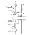
図1において38は円環状のスラストプレートである。このスラストプレート38は、可動スクロール22の鏡板31の背面側に形成された背圧室39と、圧縮機構ハウジング7内の圧縮機構4の外側の吸入圧領域としての吸入部37とを区画するためのものであり、ボス33の外側に位置してフレーム部7Bと可動スクロール22の間に介設されている。41は可動スクロール22の鏡板31の背面に取り付けられてスラストプレート38に当接するシール材であり、このシール材41とスラストプレート38により背圧室39と吸入部37とが区画される。
In FIG. 1,
尚、このスラストプレート38には本発明の連通部を構成する連通孔48が穿設されている。また、42はフレーム部7Bのスラストプレート38側の面に取り付けられてスラストプレート38の外周部に当接し、フレーム部7Bとスラストプレート38間をシールするシール材である。
The
43は圧縮機構カバー9から圧縮機構ハウジング7に渡って形成された背圧通路であり、この背圧通路43内にはオリフィス44が取り付けられている。この背圧通路43は圧縮機構カバー9内の吐出空間27内と背圧室39とを連通しており、これにより、背圧室39にはオリフィス44で減圧調整された吐出圧が供給されるように構成されている。この背圧室39内の圧力(背圧)により、可動スクロール22を固定スクロール21に押し付ける背圧荷重が生じる。この背圧荷重により、圧縮機構4の圧縮室34からの圧縮反力に抗して可動スクロール22が固定スクロール21に押し付けられ、ラップ24、32と鏡板31、23との接触が維持され、圧縮室34で冷媒を圧縮可能となる。
尚、図1の実施例では回転軸14内にオイル通路46が形成され、このオイル通路46内には圧力調整弁47が設けられている。オイル通路46は背圧室39とメインハウジング6内(吸入圧領域)とを連通しているが、圧力調整弁47は背圧室39内の圧力(背圧)が最大値となった場合に開放し、それ以上背圧が上昇しないように機能する。
In the embodiment of FIG. 1, an
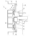
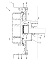
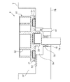
次に、図3は固定スクロール21を除く圧縮機構4部分の断面を拡大して示している。尚、図3の場合、圧力調整弁47をフレーム部7Bに取り付けた例で示している。実施例の場合、前述した如くスラストプレート38には連通部としての連通孔48が穿設されている。この連通孔48は、背圧室39と吸入圧領域としての吸入部37とを連通するための通路であるが、可動スクロール22の公転旋回運動により開閉される。
Next, FIG. 3 shows an enlarged cross section of the
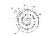
即ち、図3及び図4の如く可動スクロール22の中心X2が、当該可動スクロール22の旋回中心X1より連通孔48側に移動したときは、可動スクロール22のシール材41が連通孔48の外側に位置することになり、連通孔48は背圧室39内に位置する。即ち、この状態では連通孔48は可動スクロール22の鏡板31により閉じられ、吸入部37と背圧室39は連通されない。
3 and 4, when the center X2 of the
一方、図5及び図6の如く可動スクロール22の中心X2が旋回中心X1に対して連通孔48とは反対側に移動したときは、連通孔48は可動スクロール22のシール材41より外側に位置することになり、この状態で連通孔48は背圧室39と吸入部37とに開口し、背圧室39と吸入部37とを連通する。これにより、背圧室39内の圧力(背圧)は吸入部37に逃げるので、背圧荷重は低下することになる。
On the other hand, when the center X2 of the
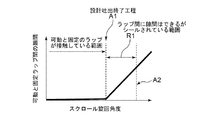
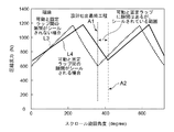
次に、この連通孔48を形成する位置について説明する。図7は固定スクロール21のラップ24と可動スクロール22のラップ32の隙間と可動スクロール22の旋回角度の関係、図8は圧縮機構4内の圧縮室34の圧力と旋回角度の関係、図9は可動スクロール22に加わる圧縮反力と旋回角度の関係をそれぞれ示している。
Next, the position where the
両ラップ24、32の中心側の端部は、図2に示すように接触している状態から、設計吐出終了工程の旋回角度A1にて離れ始める。しかしながら、ラップ24、32間は、設計吐出終了工程の旋回角度A1を過ぎても、それより遅れた所定の旋回角度A2までの範囲R1では、冷媒と共に封入される摺動部潤滑用のオイルによって、ラップ24、32間は実質的にシールされている(図7)。そのため、圧縮機構4の圧縮室34の圧力は、理論的には図8に破線L1で示すように吸入圧から吐出圧に向けて変化すると考えられるが、オイルによるシールにより、圧力は図8に実線L2で示す如く設計吐出終了工程の旋回角度A1よりこの範囲R1だけ遅れた旋回角度A2まで吐出圧が維持されることになる。
The ends on the center side of both
従って、固定スクロール21から可動スクロール22を引き離す方向に当該可動スクロール22に加わる圧縮反力は、理論的には図9に破線L3で示すように設計吐出終了工程の旋回角度A1で最小となる変化を示すものの、実際には実線L4で示す如く旋回角度A1から所定角度遅れた旋回角度A2にて最小となる変化を示すことになる。
Therefore, the compression reaction force applied to the
そのため、例えば、連通孔48が開放される可動スクロール22の旋回角度を、設計吐出終了工程の旋回角度A1に設定した場合、背圧室39からの背圧荷重は、図10に破線L5で示す如く旋回角度A1で最小となるように低下してしまうため、実線L4で示す実際の圧縮反力の低下よりも早く低下し、逆転してしまう。圧縮反力に対して背圧荷重が小さくなると、可動スクロール22が固定スクロール21から離れてしまい、圧縮不良を来すことになる。
Therefore, for example, when the turning angle of the
そこで、本発明では可動スクロール22が、設計吐出終了工程の旋回角度A1より前記範囲R1分の所定の旋回角度だけ遅れた前述の旋回角度A2(図9、図10にL4で示す実際の圧縮反力が最小となる旋回角度)となったときに図5及び図6に示す如く開放される位置に連通孔48を形成した。これにより、図10に実線L6で示す如く実際に圧縮反力が最小となる旋回角度と、背圧荷重が最小となる旋回角度とが的確に一致することになる。
Therefore, in the present invention, the
このように、本発明では背圧室39と吸入部37(吸入圧領域)とを連通するための連通孔48を形成し、この連通孔48が、圧縮機構4の設計吐出終了工程の旋回角度A1より所定の角度だけ遅れた旋回角度A2において背圧室39と吸入部37とを連通するようにしたので、可動スクロール22の公転旋回運動の一回転中で大きく変動する圧縮反力が低下する適切な角度にて背圧室39からの背圧荷重を低下させることができるようになる。これにより、圧縮機構4において圧縮不良を引き起こすこと無く、両スクロール21、22間の摩擦力を低減して、消費動力の増大を解消することができるようになる。
Thus, in the present invention, the
特に、連通孔48が、圧縮機構4の設計吐出終了工程の旋回角度A1より、各ラップ21、22間がオイルシールされている範囲R1だけ遅れた旋回角度A2において背圧室39と吸入部37とを連通するようにしているので、設計吐出終了工程の後も、オイルで各ラップ21、22間がシールされることによる圧縮反力の低下の遅れに合わせて的確に背圧荷重を低下させることができるようになる。
In particular, the
また、実施例では可動スクロール22の鏡板31の背面に接触して背圧室39と吸入部37とを区画するスラストプレート38に連通孔48を形成しているので、圧縮機構ハウジング7に直接形成する場合に比して、生産性が極めて良好となる。また、実施例では背圧室39と吸入部37とに開口した連通孔48にて背圧室39と吸入部37を連通する連通部を構成しているので、加工性も良好と成る。
Further, in the embodiment, since the
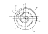
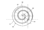
尚、前記実施例では連通孔48により本発明の連通部を構成したが、それに限らず、図11〜図13に示す如き溝(連通溝51と称する)にて連通部を構成してもよい。その場合は、スラストプレート38の可動スクロール22側の面に、当該可動スクロール22の半径方向に長い連通溝51を形成する。
In the above embodiment, the communication portion of the present invention is configured by the
そして、この連通溝51も可動スクロール22の公転旋回運動により開閉され、開放された状態で背圧室39と吸入部37とを連通するようにし、連通溝51を形成する位置も前述と同様に可動スクロール22が、設計吐出終了工程の旋回角度A1より前記範囲R1分の所定の旋回角度だけ遅れた前述の旋回角度A2となったときに開放される位置とする。
The
即ち、図13の如く可動スクロール22の中心X2が、当該可動スクロール22の旋回中心X1より連通溝51側に移動したときは、可動スクロール22のシール材41が連通溝51の外端よりも外側に位置するようにする。この状態では連通溝51は背圧室39内に位置するので、連通溝51の全体が可動スクロール22の鏡板31により閉じられ、吸入部37と背圧室39は連通されない。
That is, as shown in FIG. 13, when the center X2 of the
一方、図11及び図12の如く可動スクロール22の中心X2が旋回中心X1に対して連通溝51とは反対側に移動し、前述した旋回角度A2となったときは、連通溝51の外側の一部が可動スクロール22のシール材41より外側に位置するようにする。この状態で連通溝51は背圧室39から吸入部37に渡り、その内側が背圧室39に開口し、外側が吸入部37に開口することになるので、背圧室39と吸入部37とが連通される。これにより、背圧室39内の圧力(背圧)は吸入部37に逃げるので、前記実施例と同様に背圧荷重は低下することになる。
On the other hand, as shown in FIGS. 11 and 12, when the center X2 of the
このように、スラストプレート38に背圧室39から吸入部37(吸入圧領域9に渡る連通溝51により連通部を構成した場合にも、同様に加工性が良好となる。
As described above, when the communication portion is formed by the
また、上記各実施例ではスラストプレート38が設けられるスクロール圧縮機1にて本発明を説明したが、スラストプレートを有しないタイプのスクロール圧縮機の場合には、図14に示す如く圧縮機構ハウジング7のフレーム部7Bの可動スクロール22側の面に、上記実施例と同様の形状の連通溝52(連通部)を同様の旋回角度A2で開く位置に形成すればよい。但し、その場合にはシール材41が直接フレーム部7Bに当接して背圧室39と吸入部37とがシールされ、区画されることになる。
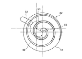
In the above embodiments, the present invention has been described with the
即ち、その場合には図16の如く可動スクロール22の中心X2が、当該可動スクロール22の旋回中心X1より連通溝52側に移動したときは、可動スクロール22のシール材41が連通溝52の外端よりも外側に位置するようにする。この状態では連通溝52は背圧室39内に位置するので、連通溝52の全体が可動スクロール22の鏡板31により閉じられ、吸入部37と背圧室39は連通されない。
That is, in this case, as shown in FIG. 16, when the center X2 of the
一方、図14及び図15の如く可動スクロール22の中心X2が旋回中心X1に対して連通溝52とは反対側に移動し、前述した旋回角度A2となったときは、連通溝52の外側の一部が可動スクロール22のシール材41より外側に位置するようにする。この状態で連通溝52は背圧室39から吸入部37に渡り、その内側が背圧室39に開口し、外側が吸入部37に開口することになるので、背圧室39と吸入部37とが連通される。これにより、背圧室39内の圧力(背圧)は吸入部37に逃げるので、前記各実施例と同様に背圧荷重は低下することになる。
On the other hand, as shown in FIGS. 14 and 15, when the center X2 of the
尚、スラストプレートが設けられない場合にも、フレーム部7Bに前述した如き連通孔を形成して連通部を構成してもよい、この実施例の如く連通溝52を形成する方が加工性は良好となる。
Even when the thrust plate is not provided, the communication portion may be formed by forming the communication hole as described above in the
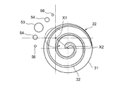
次に、図17は前述した実施例の如き連通孔(連通部)を複数形成した例を示している。この場合の連通孔53、54、56も前述同様にスラストプレート38に形成されるものであるが、実施例の場合には前述した可動スクロール22の旋回角度A2で開く位置に先ず通路面積の最も大きい第1の連通孔53(大孔)が形成されている。そして、この旋回角度A2を中心にとした所定の旋回角度の範囲に、次に通路面積が大きい第2の連通孔54(中孔)と、最も通路面積が小さい第3の連通孔56(小孔)がそれぞれ二つずつ形成されている。
Next, FIG. 17 shows an example in which a plurality of communication holes (communication portions) as in the embodiment described above are formed. The communication holes 53, 54, and 56 in this case are also formed in the
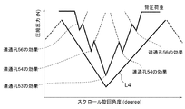
この場合、第2の連通孔54は第1の連通孔53の旋回角度において両側にそれぞれ形成され、第3の連通孔56は各第2の連通孔54の第1の連通孔53とは反対側にそれぞれ形成されている。このような構成としたことで、第3の連通孔56が開いたときは背圧荷重が少し低下し、第2の連通孔54が開いたときは更に低下し、第1の連通孔53が開いたときは最も低下するようになるので、図18に各連通孔53、54、56の効果として示すように、実際の圧縮反力(図19の実線L4)の低下に略沿って背圧荷重を低下させることが可能となる。これにより、両スクロール21、22間の摩擦力をより一層好適に低減することができるようになる。
In this case, the second communication holes 54 are formed on both sides at the turning angle of the
尚、実施例では車両用空気調和装置の冷媒回路に使用されるスクロール圧縮機に本発明を適用したが、それに限らず、各種冷凍装置の冷媒回路で使用されるスクロール圧縮機に本発明は有効である。また、実施例では所謂インバータ一体型のスクロール圧縮機に本発明を適用したが、それに限らず、インバータを一体に備えない通常のスクロール圧縮機にも適用可能である。 In the embodiment, the present invention is applied to the scroll compressor used in the refrigerant circuit of the vehicle air conditioner. However, the present invention is not limited to this, and the present invention is effective for the scroll compressor used in the refrigerant circuit of various refrigeration apparatuses. It is. In the embodiments, the present invention is applied to a so-called inverter-integrated scroll compressor. However, the present invention is not limited to this, and the present invention can also be applied to a normal scroll compressor not integrally provided with an inverter.
1 スクロール圧縮機
2 電動モータ
3 インバータ
4 圧縮機構
6 メインハウジング
7 圧縮機構ハウジング
8 インバータカバー
9 圧縮機構カバー
21 固定スクロール
22 可動スクロール
24、32 ラップ
23、31 鏡板
34 圧縮室
37 吸入部(吸入圧領域)
38 スラストプレート
39 背圧室
41 シール材
48、53、54、56 連通孔(連通部
51、52 連通溝(連通部)
DESCRIPTION OF
38
Claims (6)
前記可動スクロールの鏡板の背面に形成された背圧室と、
公転旋回運動する前記可動スクロールにより開閉され、前記背圧室と吸入圧領域とを連通するための連通部を備え、
該連通部は、前記圧縮機構の設計吐出終了工程より所定の旋回角度だけ遅れた角度において前記背圧室と前記吸入圧領域とを連通することを特徴とするスクロール圧縮機。 A compression mechanism composed of a fixed scroll and a movable scroll each having a spiral wrap formed on each surface of each end plate so as to face each other, and by rotating the movable scroll with respect to the fixed scroll, In a scroll compressor that compresses a working fluid in a compression chamber formed between the wraps,
A back pressure chamber formed on the back of the end plate of the movable scroll;
Opened and closed by the orbiting scroll that revolves and revolves, and includes a communicating portion for communicating the back pressure chamber and the suction pressure region;
The communication portion communicates the back pressure chamber and the suction pressure region at an angle delayed by a predetermined turning angle from the design discharge end step of the compression mechanism.
前記連通部は、前記スラストプレートに形成されていることを特徴とする請求項1乃至請求項3のうちの何れかに記載のスクロール圧縮機。 A thrust plate for contacting the back surface of the end plate of the movable scroll and partitioning the back pressure chamber and the suction pressure region;
The scroll compressor according to any one of claims 1 to 3, wherein the communication portion is formed in the thrust plate.
Priority Applications (4)
| Application Number | Priority Date | Filing Date | Title |
|---|---|---|---|
| JP2016050888A JP6738170B2 (en) | 2016-03-15 | 2016-03-15 | Scroll compressor |
| DE112017001321.6T DE112017001321T5 (en) | 2016-03-15 | 2017-02-24 | scroll compressor |
| CN201780015491.9A CN108700070A (en) | 2016-03-15 | 2017-02-24 | Screw compressor |
| PCT/JP2017/008394 WO2017159393A1 (en) | 2016-03-15 | 2017-02-24 | Scroll compressor |
Applications Claiming Priority (1)
| Application Number | Priority Date | Filing Date | Title |
|---|---|---|---|
| JP2016050888A JP6738170B2 (en) | 2016-03-15 | 2016-03-15 | Scroll compressor |
Publications (2)
| Publication Number | Publication Date |
|---|---|
| JP2017166366A true JP2017166366A (en) | 2017-09-21 |
| JP6738170B2 JP6738170B2 (en) | 2020-08-12 |
Family
ID=59852265
Family Applications (1)
| Application Number | Title | Priority Date | Filing Date |
|---|---|---|---|
| JP2016050888A Active JP6738170B2 (en) | 2016-03-15 | 2016-03-15 | Scroll compressor |
Country Status (4)
| Country | Link |
|---|---|
| JP (1) | JP6738170B2 (en) |
| CN (1) | CN108700070A (en) |
| DE (1) | DE112017001321T5 (en) |
| WO (1) | WO2017159393A1 (en) |
Cited By (5)
| Publication number | Priority date | Publication date | Assignee | Title |
|---|---|---|---|---|
| CN109763982A (en) * | 2019-01-11 | 2019-05-17 | 郑州跃博新能源汽车科技有限公司 | A kind of exhaust structure reducing flow resistance |
| KR20200109621A (en) * | 2019-03-13 | 2020-09-23 | 한온시스템 주식회사 | Scroll compressor |
| KR20210082790A (en) * | 2019-12-26 | 2021-07-06 | 엘지전자 주식회사 | Scroll compressor |
| DE112020001381T5 (en) | 2019-03-20 | 2021-12-02 | Sanden Automotive Components Corporation | Scroll compressor |
| US11867173B2 (en) | 2019-03-22 | 2024-01-09 | Sanden Corporation | Scroll compressor |
Families Citing this family (2)
| Publication number | Priority date | Publication date | Assignee | Title |
|---|---|---|---|---|
| JP7523370B2 (en) * | 2021-01-22 | 2024-07-26 | サンデン株式会社 | Scroll Compressor |
| CN118346606B (en) * | 2023-01-13 | 2025-09-09 | 比亚迪股份有限公司 | Scroll compressor having a rotor with a rotor shaft having a rotor shaft with a |
Citations (3)
| Publication number | Priority date | Publication date | Assignee | Title |
|---|---|---|---|---|
| JPS61178589A (en) * | 1985-01-31 | 1986-08-11 | Matsushita Electric Ind Co Ltd | scroll compressor |
| JPS61232396A (en) * | 1985-04-05 | 1986-10-16 | Matsushita Electric Ind Co Ltd | Scroll compressor |
| JP2012092773A (en) * | 2010-10-28 | 2012-05-17 | Hitachi Appliances Inc | Scroll compressor |
Family Cites Families (3)
| Publication number | Priority date | Publication date | Assignee | Title |
|---|---|---|---|---|
| JPH0979151A (en) * | 1995-09-11 | 1997-03-25 | Sanyo Electric Co Ltd | Scroll compressor |
| JP4440564B2 (en) * | 2003-06-12 | 2010-03-24 | パナソニック株式会社 | Scroll compressor |
| JP5272031B2 (en) * | 2011-03-10 | 2013-08-28 | 日立アプライアンス株式会社 | Scroll compressor |
-
2016
- 2016-03-15 JP JP2016050888A patent/JP6738170B2/en active Active
-
2017
- 2017-02-24 CN CN201780015491.9A patent/CN108700070A/en active Pending
- 2017-02-24 DE DE112017001321.6T patent/DE112017001321T5/en not_active Withdrawn
- 2017-02-24 WO PCT/JP2017/008394 patent/WO2017159393A1/en not_active Ceased
Patent Citations (3)
| Publication number | Priority date | Publication date | Assignee | Title |
|---|---|---|---|---|
| JPS61178589A (en) * | 1985-01-31 | 1986-08-11 | Matsushita Electric Ind Co Ltd | scroll compressor |
| JPS61232396A (en) * | 1985-04-05 | 1986-10-16 | Matsushita Electric Ind Co Ltd | Scroll compressor |
| JP2012092773A (en) * | 2010-10-28 | 2012-05-17 | Hitachi Appliances Inc | Scroll compressor |
Cited By (7)
| Publication number | Priority date | Publication date | Assignee | Title |
|---|---|---|---|---|
| CN109763982A (en) * | 2019-01-11 | 2019-05-17 | 郑州跃博新能源汽车科技有限公司 | A kind of exhaust structure reducing flow resistance |
| KR20200109621A (en) * | 2019-03-13 | 2020-09-23 | 한온시스템 주식회사 | Scroll compressor |
| KR102649532B1 (en) * | 2019-03-13 | 2024-03-21 | 한온시스템 주식회사 | Scroll compressor |
| DE112020001381T5 (en) | 2019-03-20 | 2021-12-02 | Sanden Automotive Components Corporation | Scroll compressor |
| US11867173B2 (en) | 2019-03-22 | 2024-01-09 | Sanden Corporation | Scroll compressor |
| KR20210082790A (en) * | 2019-12-26 | 2021-07-06 | 엘지전자 주식회사 | Scroll compressor |
| KR102332364B1 (en) * | 2019-12-26 | 2021-11-26 | 엘지전자 주식회사 | Scroll compressor |
Also Published As
| Publication number | Publication date |
|---|---|
| WO2017159393A1 (en) | 2017-09-21 |
| CN108700070A (en) | 2018-10-23 |
| DE112017001321T5 (en) | 2019-01-03 |
| JP6738170B2 (en) | 2020-08-12 |
Similar Documents
| Publication | Publication Date | Title |
|---|---|---|
| JP6738170B2 (en) | Scroll compressor | |
| JP7349279B2 (en) | scroll compressor | |
| US9157438B2 (en) | Scroll compressor with bypass hole | |
| WO2003076808A1 (en) | Scroll type fluid machine | |
| US11933297B2 (en) | Scroll compressor | |
| JP6555543B2 (en) | Scroll compressor | |
| US20190078567A1 (en) | Scroll compressor with bypass portions | |
| JPWO2017158665A1 (en) | Scroll compressor | |
| US10247188B2 (en) | Scroll compressor | |
| KR20200132421A (en) | Scroll-type compressor | |
| JP6961413B2 (en) | Scroll type fluid machine | |
| WO2020189602A1 (en) | Scroll compressor | |
| JPH09112450A (en) | Scroll compressor | |
| WO2019021712A1 (en) | Scroll fluid machine | |
| WO2024062859A1 (en) | Electric compressor | |
| JP2020148114A (en) | Scroll compressor | |
| WO2025079602A1 (en) | Compressor | |
| JP2024030222A (en) | scroll compressor | |
| JP2002138975A (en) | Scroll compressor | |
| KR20160122313A (en) | Scroll compressor | |
| JP2006152929A (en) | Scroll compressor | |
| JP2015183654A (en) | Scroll type compressor | |
| JP2012132314A (en) | Scroll compressor |
Legal Events
| Date | Code | Title | Description |
|---|---|---|---|
| A621 | Written request for application examination |
Free format text: JAPANESE INTERMEDIATE CODE: A621 Effective date: 20190306 |
|
| A131 | Notification of reasons for refusal |
Free format text: JAPANESE INTERMEDIATE CODE: A131 Effective date: 20200310 |
|
| A521 | Request for written amendment filed |
Free format text: JAPANESE INTERMEDIATE CODE: A523 Effective date: 20200501 |
|
| TRDD | Decision of grant or rejection written | ||
| A01 | Written decision to grant a patent or to grant a registration (utility model) |
Free format text: JAPANESE INTERMEDIATE CODE: A01 Effective date: 20200630 |
|
| A61 | First payment of annual fees (during grant procedure) |
Free format text: JAPANESE INTERMEDIATE CODE: A61 Effective date: 20200717 |
|
| R150 | Certificate of patent or registration of utility model |
Ref document number: 6738170 Country of ref document: JP Free format text: JAPANESE INTERMEDIATE CODE: R150 |
|
| S111 | Request for change of ownership or part of ownership |
Free format text: JAPANESE INTERMEDIATE CODE: R313111 |
|
| R360 | Written notification for declining of transfer of rights |
Free format text: JAPANESE INTERMEDIATE CODE: R360 |
|
| R360 | Written notification for declining of transfer of rights |
Free format text: JAPANESE INTERMEDIATE CODE: R360 |
|
| R371 | Transfer withdrawn |
Free format text: JAPANESE INTERMEDIATE CODE: R371 |
|
| S111 | Request for change of ownership or part of ownership |
Free format text: JAPANESE INTERMEDIATE CODE: R313111 |
|
| R350 | Written notification of registration of transfer |
Free format text: JAPANESE INTERMEDIATE CODE: R350 |