JP2017166460A - 内燃機関の可変動弁機構 - Google Patents
内燃機関の可変動弁機構 Download PDFInfo
- Publication number
- JP2017166460A JP2017166460A JP2016055014A JP2016055014A JP2017166460A JP 2017166460 A JP2017166460 A JP 2017166460A JP 2016055014 A JP2016055014 A JP 2016055014A JP 2016055014 A JP2016055014 A JP 2016055014A JP 2017166460 A JP2017166460 A JP 2017166460A
- Authority
- JP
- Japan
- Prior art keywords
- arm
- inner arm
- outer arm
- variable valve
- valve mechanism
- Prior art date
- Legal status (The legal status is an assumption and is not a legal conclusion. Google has not performed a legal analysis and makes no representation as to the accuracy of the status listed.)
- Granted
Links
Images


Classifications
-
- F—MECHANICAL ENGINEERING; LIGHTING; HEATING; WEAPONS; BLASTING
- F01—MACHINES OR ENGINES IN GENERAL; ENGINE PLANTS IN GENERAL; STEAM ENGINES
- F01L—CYCLICALLY OPERATING VALVES FOR MACHINES OR ENGINES
- F01L1/00—Valve-gear or valve arrangements, e.g. lift-valve gear
- F01L1/20—Adjusting or compensating clearance
- F01L1/22—Adjusting or compensating clearance automatically, e.g. mechanically
-
- F—MECHANICAL ENGINEERING; LIGHTING; HEATING; WEAPONS; BLASTING
- F01—MACHINES OR ENGINES IN GENERAL; ENGINE PLANTS IN GENERAL; STEAM ENGINES
- F01L—CYCLICALLY OPERATING VALVES FOR MACHINES OR ENGINES
- F01L1/00—Valve-gear or valve arrangements, e.g. lift-valve gear
- F01L1/12—Transmitting gear between valve drive and valve
- F01L1/18—Rocking arms or levers
- F01L1/185—Overhead end-pivot rocking arms
-
- F—MECHANICAL ENGINEERING; LIGHTING; HEATING; WEAPONS; BLASTING
- F01—MACHINES OR ENGINES IN GENERAL; ENGINE PLANTS IN GENERAL; STEAM ENGINES
- F01L—CYCLICALLY OPERATING VALVES FOR MACHINES OR ENGINES
- F01L1/00—Valve-gear or valve arrangements, e.g. lift-valve gear
- F01L1/12—Transmitting gear between valve drive and valve
- F01L1/18—Rocking arms or levers
- F01L1/181—Centre pivot rocking arms
-
- F—MECHANICAL ENGINEERING; LIGHTING; HEATING; WEAPONS; BLASTING
- F01—MACHINES OR ENGINES IN GENERAL; ENGINE PLANTS IN GENERAL; STEAM ENGINES
- F01L—CYCLICALLY OPERATING VALVES FOR MACHINES OR ENGINES
- F01L1/00—Valve-gear or valve arrangements, e.g. lift-valve gear
- F01L1/46—Component parts, details, or accessories, not provided for in preceding subgroups
- F01L1/462—Valve return spring arrangements
-
- F—MECHANICAL ENGINEERING; LIGHTING; HEATING; WEAPONS; BLASTING
- F01—MACHINES OR ENGINES IN GENERAL; ENGINE PLANTS IN GENERAL; STEAM ENGINES
- F01L—CYCLICALLY OPERATING VALVES FOR MACHINES OR ENGINES
- F01L13/00—Modifications of valve-gear to facilitate reversing, braking, starting, changing compression ratio, or other specific operations
- F01L13/0015—Modifications of valve-gear to facilitate reversing, braking, starting, changing compression ratio, or other specific operations for optimising engine performances by modifying valve lift according to various working parameters, e.g. rotational speed, load, torque
- F01L13/0036—Modifications of valve-gear to facilitate reversing, braking, starting, changing compression ratio, or other specific operations for optimising engine performances by modifying valve lift according to various working parameters, e.g. rotational speed, load, torque the valves being driven by two or more cams with different shape, size or timing or a single cam profiled in axial and radial direction
-
- F—MECHANICAL ENGINEERING; LIGHTING; HEATING; WEAPONS; BLASTING
- F01—MACHINES OR ENGINES IN GENERAL; ENGINE PLANTS IN GENERAL; STEAM ENGINES
- F01L—CYCLICALLY OPERATING VALVES FOR MACHINES OR ENGINES
- F01L13/00—Modifications of valve-gear to facilitate reversing, braking, starting, changing compression ratio, or other specific operations
- F01L13/0005—Deactivating valves
-
- F—MECHANICAL ENGINEERING; LIGHTING; HEATING; WEAPONS; BLASTING
- F01—MACHINES OR ENGINES IN GENERAL; ENGINE PLANTS IN GENERAL; STEAM ENGINES
- F01L—CYCLICALLY OPERATING VALVES FOR MACHINES OR ENGINES
- F01L1/00—Valve-gear or valve arrangements, e.g. lift-valve gear
- F01L1/12—Transmitting gear between valve drive and valve
- F01L1/18—Rocking arms or levers
- F01L2001/186—Split rocking arms, e.g. rocker arms having two articulated parts and means for varying the relative position of these parts or for selectively connecting the parts to move in unison
-
- F—MECHANICAL ENGINEERING; LIGHTING; HEATING; WEAPONS; BLASTING
- F01—MACHINES OR ENGINES IN GENERAL; ENGINE PLANTS IN GENERAL; STEAM ENGINES
- F01L—CYCLICALLY OPERATING VALVES FOR MACHINES OR ENGINES
- F01L1/00—Valve-gear or valve arrangements, e.g. lift-valve gear
- F01L1/46—Component parts, details, or accessories, not provided for in preceding subgroups
- F01L2001/467—Lost motion springs
-
- F—MECHANICAL ENGINEERING; LIGHTING; HEATING; WEAPONS; BLASTING
- F01—MACHINES OR ENGINES IN GENERAL; ENGINE PLANTS IN GENERAL; STEAM ENGINES
- F01L—CYCLICALLY OPERATING VALVES FOR MACHINES OR ENGINES
- F01L13/00—Modifications of valve-gear to facilitate reversing, braking, starting, changing compression ratio, or other specific operations
- F01L13/0015—Modifications of valve-gear to facilitate reversing, braking, starting, changing compression ratio, or other specific operations for optimising engine performances by modifying valve lift according to various working parameters, e.g. rotational speed, load, torque
- F01L2013/0089—Modifications of valve-gear to facilitate reversing, braking, starting, changing compression ratio, or other specific operations for optimising engine performances by modifying valve lift according to various working parameters, e.g. rotational speed, load, torque with means for delaying valve closing
- F01L2013/0094—Modifications of valve-gear to facilitate reversing, braking, starting, changing compression ratio, or other specific operations for optimising engine performances by modifying valve lift according to various working parameters, e.g. rotational speed, load, torque with means for delaying valve closing with switchable clamp for keeping valve open
-
- F—MECHANICAL ENGINEERING; LIGHTING; HEATING; WEAPONS; BLASTING
- F01—MACHINES OR ENGINES IN GENERAL; ENGINE PLANTS IN GENERAL; STEAM ENGINES
- F01L—CYCLICALLY OPERATING VALVES FOR MACHINES OR ENGINES
- F01L2305/00—Valve arrangements comprising rollers
-
- F—MECHANICAL ENGINEERING; LIGHTING; HEATING; WEAPONS; BLASTING
- F01—MACHINES OR ENGINES IN GENERAL; ENGINE PLANTS IN GENERAL; STEAM ENGINES
- F01L—CYCLICALLY OPERATING VALVES FOR MACHINES OR ENGINES
- F01L2820/00—Details on specific features characterising valve gear arrangements
- F01L2820/02—Formulas
Landscapes
- Engineering & Computer Science (AREA)
- Mechanical Engineering (AREA)
- General Engineering & Computer Science (AREA)
- Valve Device For Special Equipments (AREA)
- Valve-Gear Or Valve Arrangements (AREA)
Abstract
【解決手段】幅方向中間部に空所39が形成されているアウタアーム30と、空所39内に揺動可能に設けられたインナアーム20と、インナアーム20とアウタアーム30とを連結した連結状態とその連結を解除した非連結状態とに切り替える切替装置40と、非連結状態のときにインナアーム20をカム10に付勢するロストモーションスプリング50とを備えている。ロストモーションスプリング50は、空所39外から空所39内にまで延びる延出部53を備えている。その延出部53は、空所39内でインナアーム20に当接する当接部53bを備え、インナアーム20の揺動に伴い揺動する。そして、アウタアーム30の上下中間部に、延出部50における当接部53bよりも揺動量が小さい箇所を通す通し孔35が、該通し孔の上下両側に繋ぎ部36を残す形で貫設されている。
【選択図】図1
Description
[i]ロストモーションスプリングは、前記延出部のみからなる板バネである態様。
[ii]ロストモーションスプリングは、空所外に設置されるコイル状のコイル部と、コイル部から空所内にまで延びる前記延出部とを備えている態様。
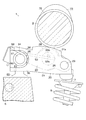
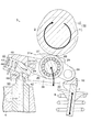
カム10は、図1等に示すように、内燃機関が2回転する毎に1回転するカムシャフト9に設けられており、そのカムシャフト9と一緒に回転する。このカム10は、図2等に示すように、断面形状が円形のベース円11と、該ベース円11から突出したノーズ12とから構成されている。また、図1等に示すように、カムシャフト9のカム10の左右両側方に位置する部位には、ベース円のみからなる休止カム15が設けられている。
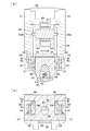
インナアーム20は、図4等に示すように、アウタアーム30の空所39に設けられており、図2等に示すように、前端部がアウタアーム30の前端部に軸材29によって揺動可能に軸着されている。そして、後端部に、カム10に当接するローラ28が、ローラシャフト26及びベアリング27を介して回転可能に取り付けられている。そして、ローラシャフト26の両端には、図3(b)等に示すように、掛合突起26bが設けられている。
アウタアーム30は、図4等に示すように、インナアーム20の左右両側に一枚ずつ設けられた側板部31と、左右の側板部31の後端どうしを繋いだ基部33とにより、前方に開いたコ字形に形成されている。そのコ字形の内側が空所39になっている。よって、アウタアーム30は、幅方向中央部に空所39を備えている。そして、左右の側板部31の前端部の下端部どうしは、架橋部32によって繋がっている。このアウタアーム30は、図2等に示すように、基部33の下面に凹設された半球状凹部33aが、ピボット60の上端の半球部63により、揺動可能に支持されている。そして、架橋部32が、バルブ7のステムエンドに当接している。そして、左右の側板部31の上端部には、休止カム15に摺接するスリッパ31aが設けられている。
切替装置40は、図2等に示すように、切替ピン41と油圧経路42とスプリング43とを含み構成されている。切替ピン41は、アウタアーム30の基部33の左右中央部に貫設された前後に延びるピン穴48の内側に取り付けられており、前側の連結位置p1と後側の非連結位置p2とに変位可能に設けられている。前側の連結位置p1は、図2等に示すように、切替ピン41の前端部が基部33から前方の空所39内に突出することで、該前端部がインナアーム20の後端部24の下方に入り込むようになる位置である。その連結位置p1に配されると、図2に矢印で示すように、インナアーム20とアウタアーム30とが、ピボット60の半球部63を軸に一緒に揺動してバルブ7を駆動するようになる。他方、後側の非連結位置p2は、図3(a)等に示すように、切替ピン41の前端部が基部33に退入することで、該前端部がインナアーム20の後端部24の下方に入り込まなくなる位置である。その非連結位置p2に配されると、図3(a)に矢印で示すように、インナアーム20がアウタアーム30に対して軸材29を軸に揺動(空振り)してバルブ7の駆動を休止するようになる。
ロストモーションスプリング50は、非連結状態のときにインナアーム20をカム10に付勢するためのスプリングであって、図4等に示すように、左側のロストモーションスプリング50と、右側のロストモーションスプリング50とがある。各ロストモーションスプリング50は、コイル部51と延出部53と第二延出部58とを含み構成されている。
7 バルブ
10 カム
20 インナアーム
30 アウタアーム
34 格納部
35 通し孔
36 繋ぎ部
39 空所
40 切替装置
50 ロストモーションスプリング
51 コイル部
53 延出部
53a 延出部の基端
53b 延出部の当接部
L1 延出部の基端から空所に差し掛かる位置までの長さ
L2 延出部の基端から当接部に差し掛かる位置までの長さ
Claims (3)
- 揺動時にはバルブ(7)を駆動し、幅方向中間部に空所(39)が形成されているアウタアーム(30)と、空所(39)内に揺動可能に設けられ、カム(10)に駆動されて揺動するインナアーム(20)と、インナアーム(20)とアウタアーム(30)とを一緒に揺動するように連結した連結状態とその連結を解除した非連結状態とに切り替える切替装置(40)と、非連結状態のときにインナアーム(20)をカム(10)に付勢するロストモーションスプリング(50)とを備えた可変動弁機構において、
ロストモーションスプリング(50)は、空所(39)外から空所(39)内にまで延びる延出部(53)を備え、延出部(53)は、空所(39)内でインナアーム(20)に当接する当接部(53b)を備え、インナアーム(20)の揺動に伴い揺動するように構成され、
アウタアーム(30)の上下中間部に、延出部(53)における当接部(53b)よりも揺動量が小さい箇所をその揺動を許容するように通す通し孔(35)が、該通し孔の上下両側に繋ぎ部(36)を残す形で貫設されていることを特徴とする内燃機関の可変動弁機構。 - ロストモーションスプリング(50)は、空所(39)外に設置されるコイル状のコイル部(51)と、コイル部(51)から空所(39)内にまで延びる前記延出部(53)とを備え、
延出部(53)は、その基端(53a)から通し孔(35)を通過して空所(39)に差し掛かる位置までの長さ(L1)が、該基端(53a)から当接部(53b)に差し掛かる位置までの長さ(L2)の50%以下である請求項1記載の内燃機関の可変動弁機構。 - アウタアーム(30)にコイル部(51)を格納する格納部(34)が設けられ、格納部(34)の一部は空所(39)にまで連通しており、該連通している部分が前記通し孔(35)を構成している請求項2記載の内燃機関の可変動弁機構。
Priority Applications (4)
| Application Number | Priority Date | Filing Date | Title |
|---|---|---|---|
| JP2016055014A JP6571569B2 (ja) | 2016-03-18 | 2016-03-18 | 内燃機関の可変動弁機構 |
| US15/419,836 US10167745B2 (en) | 2016-03-18 | 2017-01-30 | Variable valve mechanism of internal combustion engine |
| DE102017103380.7A DE102017103380A1 (de) | 2016-03-18 | 2017-02-20 | Variabler ventilmechanismus einer brennkraftmaschine |
| GB1703762.3A GB2549840B (en) | 2016-03-18 | 2017-03-09 | Variable valve mechanism of internal combustion engine |
Applications Claiming Priority (1)
| Application Number | Priority Date | Filing Date | Title |
|---|---|---|---|
| JP2016055014A JP6571569B2 (ja) | 2016-03-18 | 2016-03-18 | 内燃機関の可変動弁機構 |
Publications (2)
| Publication Number | Publication Date |
|---|---|
| JP2017166460A true JP2017166460A (ja) | 2017-09-21 |
| JP6571569B2 JP6571569B2 (ja) | 2019-09-04 |
Family
ID=58605571
Family Applications (1)
| Application Number | Title | Priority Date | Filing Date |
|---|---|---|---|
| JP2016055014A Active JP6571569B2 (ja) | 2016-03-18 | 2016-03-18 | 内燃機関の可変動弁機構 |
Country Status (4)
| Country | Link |
|---|---|
| US (1) | US10167745B2 (ja) |
| JP (1) | JP6571569B2 (ja) |
| DE (1) | DE102017103380A1 (ja) |
| GB (1) | GB2549840B (ja) |
Cited By (1)
| Publication number | Priority date | Publication date | Assignee | Title |
|---|---|---|---|---|
| US20170268386A1 (en) * | 2016-03-18 | 2017-09-21 | Otics Corporation | Variable valve mechanism of internal combustion engine |
Families Citing this family (2)
| Publication number | Priority date | Publication date | Assignee | Title |
|---|---|---|---|---|
| GB2568107B (en) * | 2017-11-07 | 2022-11-02 | Camcon Auto Ltd | Actuation assembly and methods of operation thereof |
| DE112021001325T5 (de) * | 2020-04-06 | 2022-12-15 | Eaton Intelligent Power Limited | Schaltkipphebel mit gestanzter innenhebelkonfiguration |
Citations (3)
| Publication number | Priority date | Publication date | Assignee | Title |
|---|---|---|---|---|
| JP2014532840A (ja) * | 2011-11-06 | 2014-12-08 | イートン コーポレーションEaton Corporation | ラッチピンアセンブリ |
| US20150275712A1 (en) * | 2014-03-31 | 2015-10-01 | Schaeffler Technologies AG & Co. KG | Switchable finger follower with normally unlocked coupling element |
| JP2015534005A (ja) * | 2012-11-05 | 2015-11-26 | イートン コーポレーションEaton Corporation | 内燃機関における気筒休止のためのスイッチングローラーフィンガーフォロワーの開発 |
Family Cites Families (8)
| Publication number | Priority date | Publication date | Assignee | Title |
|---|---|---|---|---|
| US6532920B1 (en) | 2002-02-08 | 2003-03-18 | Ford Global Technologies, Inc. | Multipositional lift rocker arm assembly |
| US7909007B2 (en) | 2007-06-04 | 2011-03-22 | Schaeffler Kg | Roller finger follower for valve deactivation |
| US8215275B2 (en) * | 2010-08-13 | 2012-07-10 | Eaton Corporation | Single lobe deactivating rocker arm |
| US8627796B2 (en) * | 2011-04-21 | 2014-01-14 | Eaton Corporation | Pivot foot for deactivating rocker arm |
| US10196944B2 (en) * | 2014-10-10 | 2019-02-05 | Schaeffler Technologies AG & Co. KG | Mechanical lash control for a switchable roller finger follower |
| JP6326348B2 (ja) | 2014-10-21 | 2018-05-16 | 株式会社オティックス | 内燃機関の可変動弁機構 |
| EP3314097B1 (en) | 2015-06-29 | 2020-04-29 | Eaton Corporation | Switching rocker arm for internal exhaust gas recirculation with simple latch control |
| JP6571569B2 (ja) * | 2016-03-18 | 2019-09-04 | 株式会社オティックス | 内燃機関の可変動弁機構 |
-
2016
- 2016-03-18 JP JP2016055014A patent/JP6571569B2/ja active Active
-
2017
- 2017-01-30 US US15/419,836 patent/US10167745B2/en active Active
- 2017-02-20 DE DE102017103380.7A patent/DE102017103380A1/de not_active Withdrawn
- 2017-03-09 GB GB1703762.3A patent/GB2549840B/en not_active Expired - Fee Related
Patent Citations (3)
| Publication number | Priority date | Publication date | Assignee | Title |
|---|---|---|---|---|
| JP2014532840A (ja) * | 2011-11-06 | 2014-12-08 | イートン コーポレーションEaton Corporation | ラッチピンアセンブリ |
| JP2015534005A (ja) * | 2012-11-05 | 2015-11-26 | イートン コーポレーションEaton Corporation | 内燃機関における気筒休止のためのスイッチングローラーフィンガーフォロワーの開発 |
| US20150275712A1 (en) * | 2014-03-31 | 2015-10-01 | Schaeffler Technologies AG & Co. KG | Switchable finger follower with normally unlocked coupling element |
Cited By (2)
| Publication number | Priority date | Publication date | Assignee | Title |
|---|---|---|---|---|
| US20170268386A1 (en) * | 2016-03-18 | 2017-09-21 | Otics Corporation | Variable valve mechanism of internal combustion engine |
| US10167745B2 (en) * | 2016-03-18 | 2019-01-01 | Otics Corporation | Variable valve mechanism of internal combustion engine |
Also Published As
| Publication number | Publication date |
|---|---|
| DE102017103380A1 (de) | 2017-09-21 |
| US10167745B2 (en) | 2019-01-01 |
| GB2549840B (en) | 2021-03-31 |
| GB2549840A (en) | 2017-11-01 |
| GB201703762D0 (en) | 2017-04-26 |
| US20170268386A1 (en) | 2017-09-21 |
| JP6571569B2 (ja) | 2019-09-04 |
Similar Documents
| Publication | Publication Date | Title |
|---|---|---|
| JP4891793B2 (ja) | 可変動弁機構 | |
| US20110197843A1 (en) | Switchable roller finger follower | |
| JP6571569B2 (ja) | 内燃機関の可変動弁機構 | |
| JP5767603B2 (ja) | 可変動弁機構 | |
| JP2008232078A (ja) | 可変動弁機構 | |
| JP6661478B2 (ja) | 内燃機関の可変動弁機構 | |
| JP6234310B2 (ja) | 内燃機関の可変動弁機構 | |
| JP2008208746A (ja) | 可変動弁機構 | |
| JP4541471B2 (ja) | 燃焼エンジンのバルブリフトと相対的なタイミングとを同時制御するロッカアーム装置 | |
| JP6326349B2 (ja) | 内燃機関の可変動弁機構 | |
| JP6691459B2 (ja) | 内燃機関の可変動弁機構 | |
| JP2009197732A (ja) | 動弁機構 | |
| KR101055479B1 (ko) | 엔진의 동작 밸브 기구 | |
| JP6546811B2 (ja) | 内燃機関の可変動弁機構 | |
| JP2019157631A (ja) | 内燃機関の可変動弁機構 | |
| JP4833102B2 (ja) | 可変動弁機構 | |
| JP6546855B2 (ja) | 内燃機関の可変動弁機構 | |
| JP2011080380A (ja) | ロッカアーム及び動弁機構 | |
| JP4711999B2 (ja) | 可変動弁機構 | |
| JP5801747B2 (ja) | 可変動弁機構 | |
| JP6043206B2 (ja) | 内燃機関の可変動弁機構 | |
| JP2019056327A (ja) | 内燃機関の可変動弁機構 | |
| JP2009209847A (ja) | 可変動弁機構 | |
| JP2018197511A (ja) | ロッカーアーム及びこれを備えた可変動弁機構 | |
| JP2024082821A (ja) | 内燃機関の可変動弁機構 |
Legal Events
| Date | Code | Title | Description |
|---|---|---|---|
| A521 | Request for written amendment filed |
Free format text: JAPANESE INTERMEDIATE CODE: A523 Effective date: 20161220 |
|
| A621 | Written request for application examination |
Free format text: JAPANESE INTERMEDIATE CODE: A621 Effective date: 20180927 |
|
| A977 | Report on retrieval |
Free format text: JAPANESE INTERMEDIATE CODE: A971007 Effective date: 20190724 |
|
| TRDD | Decision of grant or rejection written | ||
| A01 | Written decision to grant a patent or to grant a registration (utility model) |
Free format text: JAPANESE INTERMEDIATE CODE: A01 Effective date: 20190730 |
|
| A61 | First payment of annual fees (during grant procedure) |
Free format text: JAPANESE INTERMEDIATE CODE: A61 Effective date: 20190808 |
|
| R150 | Certificate of patent or registration of utility model |
Ref document number: 6571569 Country of ref document: JP Free format text: JAPANESE INTERMEDIATE CODE: R150 |
|
| R250 | Receipt of annual fees |
Free format text: JAPANESE INTERMEDIATE CODE: R250 |
|
| R250 | Receipt of annual fees |
Free format text: JAPANESE INTERMEDIATE CODE: R250 |
|
| R250 | Receipt of annual fees |
Free format text: JAPANESE INTERMEDIATE CODE: R250 |