JP2017170102A - Seated-type cervical traction device and angle detection method therefor - Google Patents
Seated-type cervical traction device and angle detection method therefor Download PDFInfo
- Publication number
- JP2017170102A JP2017170102A JP2016080556A JP2016080556A JP2017170102A JP 2017170102 A JP2017170102 A JP 2017170102A JP 2016080556 A JP2016080556 A JP 2016080556A JP 2016080556 A JP2016080556 A JP 2016080556A JP 2017170102 A JP2017170102 A JP 2017170102A
- Authority
- JP
- Japan
- Prior art keywords
- traction
- angle
- seated
- cervical
- pressure
- Prior art date
- Legal status (The legal status is an assumption and is not a legal conclusion. Google has not performed a legal analysis and makes no representation as to the accuracy of the status listed.)
- Granted
Links
Images


Landscapes
- Orthopedics, Nursing, And Contraception (AREA)
Abstract
【課題】適時に調整できる着席式頸椎牽引装置及びその角度感知方法を提供する。
【解決手段】着席式頸椎牽引装置及びその角度感知方法は、引っ張りモジュール10、オーバーハング部材20、牽引部材33、感知モジュール40を有する。オーバーハング部材20は引っ張りモジュール10の片側に設置される。牽引部材33一端は引っ張りモジュール10に連接され、その反対端はオーバーハング部材20の一端を通して下方へと垂れ下がる。感知モジュール40はオーバーハング部材20の一端を通して下方へと垂れ下がる牽引部材33の一部分に設置される。牽引部材33を牽引すると、オーバーハング部材20の一端点は下方へと延伸し、水平面に垂直な角度を基準とし、水平面に垂直な角度を基準として牽引角度310を形成する。感知モジュール40は牽引角度を探知する。こうして、操作者は着席式頸椎牽引装置の使用者に対する牽引角度を明確に知ることができ、適時に対応する調整を行える。
【選択図】図1A seated cervical traction device that can be adjusted in a timely manner and an angle sensing method thereof.
A seated cervical traction device and an angle sensing method thereof include a tension module, an overhang member, a traction member, and a sensing module. The overhang member 20 is installed on one side of the tension module 10. One end of the traction member 33 is connected to the pull module 10, and the opposite end hangs downward through one end of the overhang member 20. The sensing module 40 is installed on a portion of the traction member 33 that hangs down through one end of the overhang member 20. When the pulling member 33 is pulled, one end point of the overhang member 20 extends downward, and forms a pulling angle 310 with an angle perpendicular to the horizontal plane as a reference and an angle perpendicular to the horizontal plane as a reference. The sensing module 40 detects the traction angle. Thus, the operator can clearly know the traction angle with respect to the user of the seated cervical traction device, and can make a corresponding adjustment in a timely manner.
[Selection] Figure 1
Description
本発明は医療設備及びその使用方式に関し、特に着席式頸椎牽引装置及びその角度感知方法に関する。 More particularly, the present invention relates to a seated cervical traction device and an angle sensing method thereof.
首と肩の痛みは現代人にしばしば出現する問題である。
長期的な姿勢不良は、骨格、筋肉或いは神経上の病的症状を引き起こす。
このような問題は、人々の生活を不便にし、生活の質を低下させてしまう。
頸部の疼痛はしばしば見られる疾病であり、個人の健康においても、医療資源全体においても、非常に重要な問題である。
Neck and shoulder pain is a problem that often appears in modern people.
Long-term poor posture causes pathological symptoms on the skeleton, muscles or nerves.
Such problems make people's lives inconvenient and reduce the quality of life.
Cervical pain is a common disease and is a very important issue both in the health of individuals and in the overall medical resource.
近年はスマートフォン、タブレット型コンピューターが発展し、オンラインでホームページを閲覧し、ビデオを視聴し、通信ソフトでチャットし、或いは携帯電話内のゲームをプレイする等その使用法はどんどん多様化している。
上述の装置はすべて携帯できるため、いつでも取り出し使用できる。
そのため、バスや電車を待っている時であろうと、車内であろうと、どんなに短い時間でも、人々はスマートフォン或いはタブレット型コンピューターを用いることができる。
しかも、スマートフォン或いはタブレット型コンピューターの使用では、下向きにスクリーンを見る必要があるため、長時間下向きにスマートフォン或いはタブレット型コンピューターを使う状況下では、頸部疼痛を生じる可能性は高くなる。
In recent years, smartphones and tablet computers have been developed, and their usage has been diversified, such as browsing online websites, watching videos, chatting with communication software, and playing games in mobile phones.
All of the above devices are portable and can be taken out and used at any time.
As a result, people can use smartphones or tablet computers no matter how short time they are waiting for a bus or train or in a car.
Moreover, since it is necessary to look down at the screen when using a smartphone or tablet computer, there is a high possibility that neck pain will occur in situations where the smartphone or tablet computer is used downward for a long time.
上述の原因は、人体の頸部及びその付近の筋肉、靭帯等の部位の関節が、バランスが崩れた圧力作用を受けることで、人体頸部位置の血液循環が悪くなり、疼痛等の不快な感覚を生じるもので、長期間抑圧を受ければ変形して痛みを発する。
前述の問題に対して、従来の東洋医学の療法では、鍼灸、マッサージ、温湿布に伝統的な推拿法を加え、その不当に圧を受ける部位を矯正し、疼痛等症状を軽減する。
伝統的な推拿治療過程では、施力の強さ及びバランスはコントロールが難しく、治療効果が大きく割り引かれてしまっている。
The above-mentioned causes are that the neck of the human body and the nearby joints such as muscles and ligaments are subjected to pressure action that is out of balance, resulting in poor blood circulation at the human neck and uncomfortable pain. It is a sensation that deforms and causes pain if it is suppressed for a long time.
In order to solve the above-mentioned problems, traditional Oriental medicine therapy uses traditional acupuncture methods for acupuncture, massage, and hot compresses to correct unreasonable pressure and reduce symptoms such as pain.
In the traditional acupuncture treatment process, the strength and balance of the applied force are difficult to control and the therapeutic effect has been greatly discounted.
よって現在では、大多数は機械による頸椎牽引を治療手段としている。
機械牽引は頸椎退化性関節炎(頸椎骨棘)或いはつい間板ヘルニアに常用される。
神経根圧迫を併発する病人に対する機械式頸椎牽引は現在臨床上では、頸肩疼痛に対する主要な保守治療方式である。
頸椎牽引は、着席式と臥式の2種に分けられる。
前者はスペースを節減でき、後者は患者が比較的楽である。
但し、後者に使用する重量は比較重い必要があり、身体とベッドとの間の抵抗を克服しなければならない。
けれども、この抵抗は、横たわって腰椎を牽引する場合より少し小さい。
現在ではやはり座って行う頸椎牽引が主流である。
その中で、着席式牽引は、牽引過程において、角度の偏移、或いは牽引圧力のコントロール不適当等の状況が発生しやすい。
牽引角度の偏移或いは牽引圧力の不適当は、治療効果に対して悪影響を及ぼし、治療の効果を低下させてしまう。
よって、これら要因をいかにして抑えるかは、非常に重要である。
Thus, the majority now uses mechanical cervical traction as a treatment.
Mechanical traction is routinely used for cervical degenerative arthritis (cervical spine) or disc herniation.
Mechanical cervical traction for patients with concurrent nerve root compression is currently the main conservative treatment for cervical shoulder pain.
Cervical traction can be divided into two types: seated type and saddle type.
The former can save space and the latter is relatively easy for the patient.
However, the weight used for the latter needs to be relatively heavy and the resistance between the body and the bed must be overcome.
However, this resistance is a little less than when lying down and pulling the lumbar spine.
At present, cervical traction is also the mainstream.
Among them, the seated traction tends to cause a situation such as an angle shift or inappropriate control of the traction pressure in the traction process.
The deviation of the pulling angle or the inappropriate pulling pressure adversely affects the therapeutic effect and reduces the therapeutic effect.
Therefore, how to suppress these factors is very important.
本発明の目的は牽引角度の変化を探知し、操作者或いは使用者に、対応する調整と修正を行うように提示でき、また本発明は牽引圧力の変化を探知し、操作者或いは使用者に、対応する調整と修正を行うように提示でき、さらに牽引角度と牽引圧力の変化を保存し、操作者或いは使用者に後続処理と診断の依拠を提供できる着席式頸椎牽引装置及びその角度感知方法を提供することにある。 The purpose of the present invention is to detect changes in the traction angle and present it to the operator or user to make the corresponding adjustments and corrections, and the present invention detects changes in the traction pressure and provides the operator or user with the change. A seated cervical traction device that can be presented to make the corresponding adjustments and corrections, further preserves changes in the traction angle and traction pressure, and provides the operator or user with a basis for subsequent processing and diagnosis, and its angle sensing method Is to provide.
本発明による着席式頸椎牽引装置は、引っ張りモジュール、オーバーハング部材、牽引部材、感知モジュールを有する。
該オーバーハング部材は、該引っ張りモジュールの片側に設置される。
該牽引部材一端は、該引っ張りモジュールに連接され、反対端は該オーバーハング部材の一端を通して下方へと垂れ下がる。
該感知モジュールは、該オーバーハング部材の一端を通して下方へと垂れ下がる牽引部材の一部分に設置される。
該オーバーハング部材の一端点は下方へと延伸し、水平面に垂直な角度を基準とし、垂れ下がる牽引部材の一部はある牽引角度の偏りを示し、該感知モジュールにより該牽引角度を感知する。
The seated cervical traction device according to the present invention includes a tension module, an overhang member, a traction member, and a sensing module.
The overhang member is installed on one side of the pull module.
One end of the traction member is connected to the pull module and the opposite end hangs down through one end of the overhang member.
The sensing module is installed on a portion of the traction member that hangs down through one end of the overhang member.
One end point of the overhang member extends downward, and a part of the hanging pulling member exhibits a certain pulling angle deviation based on an angle perpendicular to the horizontal plane, and the pulling angle is detected by the sensing module.
本発明の一実施形態において、該感知モジュールは、三軸加速度計及び/或いはジャイロスコープである。 In one embodiment of the invention, the sensing module is a three-axis accelerometer and / or a gyroscope.
本発明の一実施形態はさらに、ストレージチップを有し、該感知モジュールが該牽引角度を探知し、発する感知シグナルを保存する。 One embodiment of the present invention further comprises a storage chip, and the sensing module detects the traction angle and stores the sensing signal emitted.
本発明の一実施形態はさらに、アラームユニットを有し、それはプレ設定角度範囲を備え、該牽引角度が、プレ設定角度範囲より大きいか小さいと、該アラームユニットは、アラーム音を発する。 One embodiment of the present invention further comprises an alarm unit, which comprises a preset angle range, and when the traction angle is greater or less than the preset angle range, the alarm unit emits an alarm sound.
本発明の一実施形態において、該牽引部材は、牽引ロープと牽引ヘッドギアを有し、該牽引ロープの一端は、該引っ張りモジュールに連接され、その反対端は、該牽引ヘッドギアに連接される。 In one embodiment of the present invention, the traction member has a traction rope and a traction headgear, one end of the traction rope is connected to the pulling module, and the opposite end is connected to the traction headgear.
本発明の一実施形態において、該牽引ヘッドギアは、固定部材と少なくとも1個の環状ベルトを有し、該固定部材は、該牽引ロープの反対端に設置され、該少なくとも1個の環状ベルトは、該固定部材に固定される。 In one embodiment of the present invention, the traction headgear has a fixed member and at least one annular belt, the fixed member being installed at the opposite end of the traction rope, the at least one annular belt being It is fixed to the fixing member.
本発明の一実施形態において、該牽引ヘッドギアは、固定部材、牽引サポートフレーム、少なくとも1個の環状ベルトを有する。
該固定部材は、該牽引ロープの一端に設置され、該牽引サポートフレームは、該固定部材に固定して設置され、該少なくとも1個の環状ベルトは、該牽引サポートフレームに掛けて設置される。
In one embodiment of the present invention, the traction headgear includes a fixed member, a traction support frame, and at least one annular belt.
The fixing member is installed at one end of the traction rope, the traction support frame is fixedly installed on the fixing member, and the at least one annular belt is installed on the traction support frame.
本発明の一実施形態はさらに、圧力感知モジュールを有し、該少なくとも1個の環状ベルトの内側に設置される。 One embodiment of the present invention further comprises a pressure sensing module and is located inside the at least one annular belt.
本発明の一実施形態はさらに、ストレージユニットを有し、該圧力感知モジュールが牽引圧力を感知し発する圧力感知シグナルを保存する。 One embodiment of the present invention further includes a storage unit for storing a pressure sensing signal generated and sensed by the pressure sensing module for traction pressure.
本発明の一実施形態はさらに、アラームユニットを有し、それはプレ設定圧力範囲を備え、該牽引圧力が該プレ設定圧力範囲より大きいか、小さい時には、該アラームユニットは、アラーム音を発する。 One embodiment of the present invention further comprises an alarm unit, which comprises a preset pressure range, and when the traction pressure is greater than or less than the preset pressure range, the alarm unit emits an alarm sound.
本発明は着席式頸椎牽引の角度感知方法のステップを提供し、それは以下を含む。
牽引部材を吊り下げる。
水平面に垂直な角度を基準とし、牽引部材を基準から偏離するよう牽引し、牽引角度を形成する。
牽引角度を感知する。
The present invention provides steps of an angle sensing method for seated cervical traction, which includes:
Suspend the tow member.
Using the angle perpendicular to the horizontal plane as a reference, the traction member is pulled away from the reference to form a traction angle.
Sense the pulling angle.
本発明の一実施形態において、水平面に垂直な角度を基準とし、牽引部材を基準から偏離するよう牽引し、牽引角度を形成するステップにおいて、該牽引角度を保存する。 In an embodiment of the present invention, the traction angle is stored in the step of traction so that the traction member is deviated from the reference with an angle perpendicular to the horizontal plane as a reference, and the traction angle is formed.
本発明の一実施形態において、牽引角度を感知するステップにおいて、該牽引角度が該プレ設定角度範囲より大きいか小さいと、アラーム音を発する。 In one embodiment of the present invention, in the step of sensing the traction angle, an alarm sound is generated when the traction angle is larger or smaller than the preset angle range.
本発明の一実施形態において、水平面に垂直な角度を基準とし、牽引部材を基準から偏離するよう牽引し、該牽引角度を形成するステップにおいて、該牽引部材を牽引する牽引圧力を感知する。 In one embodiment of the present invention, the traction member is pulled away from the reference with respect to an angle perpendicular to the horizontal plane, and in the step of forming the traction angle, a traction pressure that pulls the traction member is sensed.
本発明の一実施形態において、該牽引圧力を保存する。 In one embodiment of the invention, the traction pressure is stored.
本発明の一実施形態において、該牽引圧力を感知し、該牽引圧力が該プレ設定圧力範囲より大きいか小さいと、アラーム音を発する。 In one embodiment of the invention, the traction pressure is sensed and an audible alarm is generated when the traction pressure is greater or less than the preset pressure range.
本発明は、牽引角度の変化を探知し、操作者或いは使用者に、対応する調整と修正を行うように提示でき、また本発明は牽引圧力の変化を探知し、操作者或いは使用者に、対応する調整と修正を行うように提示でき、さらに本発明は牽引角度と牽引圧力の変化を保存し、操作者或いは使用者に後続処理と診断の依拠を提供できる。 The present invention can detect changes in the traction angle and present it to the operator or user to make corresponding adjustments and corrections, and the present invention can detect changes in the traction pressure and provide the operator or user with Corresponding adjustments and corrections can be presented, and the present invention can also save changes in traction angle and traction pressure, providing the operator or user with a basis for subsequent processing and diagnosis.
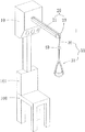
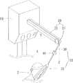
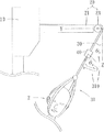
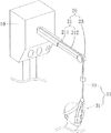
図1、図2は本発明による着席式頸椎牽引装置の立体図と使用模式図である。
図に示す通り、本実施形態は着席式頸椎牽引装置1である。
頸椎牽引は、頸椎の関節位置の病変の治療に主に用いられる。
頸椎は平均でない圧力作用を受けると、頸椎部位の血液循環が不良となり、疼痛等の不快な感覚を生じる。
さらには、頸椎は長期間圧迫を受けると、骨格変形等を生じ、より深刻な疼痛現象を発生する。
1 and 2 are a three-dimensional view and a schematic view of use of a seated cervical traction device according to the present invention.
As shown in the figure, this embodiment is a seated
Cervical traction is mainly used to treat lesions at the cervical joint position.
When the cervical vertebra is subjected to a non-average pressure action, the blood circulation in the cervical vertebra is poor, and unpleasant sensations such as pain are generated.
Furthermore, when the cervical vertebra is subjected to compression for a long period of time, it causes skeletal deformation and the like, causing a more serious pain phenomenon.
上述の状況に対して、着席式頸椎牽引は一つの治療手段である。
本実施形態による着席式頸椎牽引装置1は、引っ張りモジュール10、オーバーハング部材20、牽引部材33と感知モジュール40を有する。
オーバーハング部材20は、引っ張りモジュール10の片側に設置する。
For the situation described above, seated cervical traction is one therapeutic means.
The seated
The
牽引部材33の一端は、引っ張りモジュール10に連接され、その反対端はオーバーハング部材20の一端を通して下方へと垂れ下がる。
感知モジュール40は、オーバーハング部材20の一端を通して下方へと垂れ下がる牽引部材33の一部に設置され、オーバーハング部材20の一端点は下方へと延伸し、水平面に垂直な角度を基準とし、垂れ下がる牽引部材33の一部はある牽引角度310の偏りを示し、感知モジュール40により、該牽引角度310を探知する。
本実施形態では着席式頸椎牽引を行う過程において、牽引部材33の牽引角度310を感知できる。
こうして操作者(医者或いは看護人員等)は、牽引角度310の状況を随時知ることができ、適当に角度を調整でき、これにより頸椎牽引の治療は最良の治療効果を達成できる。
One end of the
The
In the present embodiment, the pulling
Thus, an operator (such as a doctor or a nurse) can know the situation of the
着席式頸椎牽引装置1は、引っ張りモジュール10、オーバーハング部材20、牽引部材33と感知モジュール40を有する。
オーバーハング部材20は、棒部材21と車輪軸23をさらに有する。
車輪軸23は、棒部材21の一端に枢設される。
棒部材21の反対端は、引っ張りモジュール10の片側に設置され、それは引っ張りモジュール10に垂直である。
牽引部材33一端は、引っ張りモジュール10の内部に連接される。
牽引部材33はオーバーハング部材20の棒部材21に沿って設置され、その反対端は、オーバーハング部材20の車輪軸23を通して、地面へと垂れ下がる。
牽引部材33は、牽引ロープ30と牽引ヘッドギア31を有する。
牽引ロープ30の一端は、引っ張りモジュール10に連接され、その反対端は、牽引ヘッドギア31に連接される。
牽引ヘッドギア31は、固定部材311と少なくとも1個の環状ベルト312を有する。
固定部材311は、牽引ロープ30の反対端に固定され、少なくとも1個の環状ベルト312は、固定部材311上に固定される。
感知モジュール40はオーバーハング部材20の一端を通して下方へと垂れ下がる牽引部材33の一部の上に設置され、感知モジュール40は、三軸加速度計、或いはジャイロスコープである。
本実施形態の引っ張りモジュール10は、シート100のバックレスト101上方に設置され、使用者(患者等)は着席状態で頸椎の牽引治療を行うことができる。
The seated
The
The
The opposite end of the
One end of the pulling
The pulling
The
One end of the
The
The fixing
The
The
本実施形態において、三軸加速度計は、X軸、Y軸、Z軸方向の電圧値を備える。
三軸加速度計を水平に置くと、X軸とY軸は水平面で、Z軸はX軸とY軸に垂直な水平面である。
センサーが傾斜を生じると、X軸、Y軸或いは/及びZ軸は、重力の影響を受け、その電圧数値が変わる。
さらにこれら数値は公式の演算を通して、三軸の角度変化値を算出することができる。
この部分は従来の技術であるため、ここでは説明しない。
一方、ジャイロスコープは、加速度計が感知できない角速度を感知し、回転を続けるジャイロを一定の電圧状態とする。
センサーが振動すると、ジャイロの水平を変え、しかも周囲の電圧も変わり、数値積分を算出し、物体回転の角度を導き出すことができる。
In the present embodiment, the three-axis accelerometer includes voltage values in the X-axis, Y-axis, and Z-axis directions.
When the three-axis accelerometer is placed horizontally, the X-axis and Y-axis are horizontal planes, and the Z-axis is a horizontal plane perpendicular to the X-axis and Y-axis.
When the sensor is tilted, the X-axis, Y-axis, and / or Z-axis is affected by gravity, and the voltage value changes.
Furthermore, these numerical values can be used to calculate three-axis angle change values through official calculations.
Since this part is a conventional technique, it will not be described here.
On the other hand, the gyroscope senses an angular velocity that cannot be sensed by the accelerometer, and puts the gyro that continues to rotate into a constant voltage state.
When the sensor vibrates, the gyro level changes and the surrounding voltage also changes, and the numerical integral can be calculated to derive the angle of object rotation.
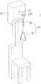
図3〜図6は本発明による着席式頸椎牽引装置の第一実施形態のXYZ空間の使用模式図、YZ平面の使用模式図、XZ平面の使用模式図、水平回転の使用模式図である。
図に示す通り、本実施形態において、着席式頸椎牽引を行う時には、使用者はシート100上に着席する。
しかも、使用者の背中はバックレスト101にもたれ、使用者の着席姿勢を固定する。
使用者の頭部2は、牽引ヘッドギア31に掛けられる。
牽引ヘッドギア31の少なくとも1個の環状ベルト312が2個の環状ベルト312である時、2個の環状ベルト312はそれぞれ第一環状ベルト313と第二環状ベルト314である。
第一環状ベルト313は、頭部2を取り囲み、その内側はそれぞれ頭部2のあごと両頬位置に接触する。
第二環状ベルト314は同様に頭部2を取り囲み、その内側は頭部2の後頭部に接触する。
3 to 6 are a usage schematic diagram of the XYZ space, a usage schematic diagram of the YZ plane, a usage schematic diagram of the XZ plane, and a usage schematic diagram of horizontal rotation of the first embodiment of the seated cervical traction device according to the present invention.
As shown in the figure, in the present embodiment, when performing seated cervical traction, the user is seated on the
In addition, the user's back rests on the
The user's
When at least one
The first
The second
本実施形態において、着席式頸椎牽引装置1により治療を行う時には、引っ張りモジュール10は牽引部材33を引いて収める。
牽引部材33の垂れ下がる部分は、車輪軸23と棒部材21の方向に沿って牽引収納される。
すなわち、牽引ロープ30の反対端は、牽引ヘッドギア31をそのままの方向に引き、同時に使用者の頭部2は、牽引ロープ30の引っ張り作用を受ける。
頭部2は外力に引っ張られた状況下で、それはそのままの方向で身体を連動し、これにより頸椎はまっすぐな状態となる。
引っ張りモジュール10は持続プル&ホールド、間歇プル&ホールド或いは段階的プル&ホールド等の引っ張り方式に設定できる。
本実施形態では、使用者の必要に応じて、上述の引っ張り方式の調整を行うことができる。
上述の状況下で、牽引部材33は頭部2を長時間プル&ホールドし、頸椎は外力作用下の角度に維持される。
このような方式により、頸椎変形を調整する治療手段を更生する。
In the present embodiment, when the treatment is performed by the seated
The portion where the pulling
In other words, the opposite end of the
In a situation where the
The
In the present embodiment, the above-described pulling method can be adjusted as required by the user.
Under the above-mentioned situation, the pulling
By such a method, the treatment means for adjusting the cervical spine deformity is renewed.
図3に合わせて示す通り、牽引部材33の垂れ下がる部分オーバーハング部材20の一端を、支点として偏移し、オーバーハング部材20の一端を三次元空間の座標軸の0点とする。
感知モジュール40は、牽引部材33の垂れ下がる部分上に設置される。
As shown in FIG. 3, one end of the
The
図4に合わせて示す通り、二次元空間では、牽引部材33はYZ平面の牽引角度310にある。
一般的に、着席式頸椎牽引治療の手段は、頭部2を引っ張ってホールドすることを利用する。
この引っ張りは、使用者の真正面(Y軸方向)と真上(Z軸方向)に対して作用する。
図に示す通り、牽引部材33が、オーバーハング部材20の一端より第一角度θ1の偏移を行うと、感知モジュール40は、牽引部材33の垂れ下がる部分において、牽引部材33の牽引角度310が第二角度θ2であると感知する。
相似三角形の原理に基づき、第二角度θ2は第一角度θ1に等しいことが分かる
よって、感知モジュール40は、着席式頸椎牽引装置の牽引過程における牽引角度310を感知できる。
As shown in FIG. 4, in the two-dimensional space, the
In general, the means for seated cervical traction therapy utilizes pulling and holding the
This pull acts on the front (Y-axis direction) and directly above (Z-axis direction) of the user.
As shown in the figure, when the
Based on the principle of similar triangles, it can be seen that the second angle θ2 is equal to the first angle θ1, so that the
図5に合わせて示す通り、二次元空間では、牽引部材33はYZ平面の牽引角度310であることが分かる。
正常状況下では、着席頸椎牽引治療の方式は、左へ偏移したり、右へ偏移したりしないはずである。
着席式牽引治療の過程では、使用者の頭部2が居眠り或いは自分自身で気付かない状況下で、牽引角度310の変化を生じることもある。
図に示す通り、牽引部材33が、オーバーハング部材20の一端から第三角度θ3の偏移を示すと、牽引部材33の垂れ下がる部分に設置された該感知モジュール40により、牽引部材33の牽引角度310を感知し、同様に相似三角形の原理に基づき、第三角度θ3を知ることができる。
As shown in FIG. 5, in the two-dimensional space, it can be seen that the
Under normal circumstances, a seated cervical traction therapy scheme should not shift to the left or to the right.
In the process of the seated traction treatment, the
As shown in the figure, when the pulling
図6は、牽引角度310の角度変化を示す。
図に示す通り、図6は、XY平面の牽引角度310、つまり第一角度θ1が図4の牽引角度310と相同だと示すが、図6ではさらに回転角度を追加する。
使用者の頭部2がある角度の回転を行うと、牽引角度310は同様に第一角度θ1であるが、使用者の頭部2の回転によって、変化しない。
しかし、頭部2の回転は、牽引部材33の牽引ロープ30の回転をもたらす他、この状況では、頸椎牽引治療に対して深刻な影響を及ぼし、治療効果が得られないばかりか、頸椎に対して深刻な傷害を及ぼす恐れさえある。
よって、感知モジュール40が牽引ロープ30の回転を感知すると、牽引ロープ30は角度θ4の回転を行う。
こうして、正確に頸椎牽引の角度を制御でき、治療の効果を高めることができる。
FIG. 6 shows the change in the
As shown in the figure, FIG. 6 shows that the pulling
When the user's
However, the rotation of the
Therefore, when the
In this way, the angle of cervical traction can be accurately controlled, and the therapeutic effect can be enhanced.
本実施形態は従来の技術の欠点に対して改良を加える。
従来の技術の着席式頸椎牽引装置は、頸椎牽引等治療手段に用いることができる。
しかし、頸椎牽引治療を行う過程では、使用者(患者等)が居眠り或いは自分自身でも察知できない状況下で、頭部が左右に偏移或いは回転し、これにより頸椎牽引の牽引角度は操作者(医師或いは看護人員等)がもともと設定した頸椎矯正の治療角度と違ってくることがある。
このような状況下で、治療効果が不良となり、或いは頸椎傷害等の状況を生じる恐れがある。
This embodiment adds improvements to the drawbacks of the prior art.
Conventional seated cervical traction devices can be used for therapeutic means such as cervical traction.
However, in the process of performing cervical traction therapy, the head is shifted or rotated left and right in a situation where the user (patient or the like) is asleep or undetectable by himself, so that the traction angle of cervical traction is determined by the operator ( It may be different from the treatment angle of cervical spine correction originally set by a doctor or a nurse.
Under such circumstances, there is a risk that the therapeutic effect becomes poor or a situation such as cervical spine injury occurs.
よって、本実施形態は、着席式頸椎牽引装置を提供し、オーバーハング部材20の一端が下方へと垂れ下がる牽引部材33のロープセクションに設置される感知モジュール40を利用する。
牽引部材33を牽引し、使用者の頭部を引っ張ってホールドする時、オーバーハング部材20の一端点は下方へと延伸し、水平面に垂直な角度を基準とする。
水平面に垂直な角度の基準に基づき、牽引部材33がこの基準に対して、牽引角度310を偏移すれば、感知モジュール40は牽引角度310を感知できる。
こうして操作者は、着席式頸椎牽引装置1の使用者に対する牽引角度310即時に、しかも明確に知ることができ、対応する調整を適時に行うことができ、こうして最良の治療手段と効果を提供することができる。
Thus, this embodiment provides a seated cervical traction device and utilizes a
When the pulling
If the
Thus, the operator can immediately and clearly know the
図7は、本発明による着席式頸椎牽引装置の第二実施形態模式図である。
図に示す通り、本実施形態と第一実施形態との差異は、以下の通りである。
本実施形態は、圧力感知モジュール50をさらに有する。
圧力感知モジュール50は牽引ヘッドギア31の少なくとも1個の環状ベルト312の内側に設置される。
使用者は、牽引ヘッドギア31を装着し、少なくとも1個の環状ベルト312の第一環状ベルト313は、頭部2を取り囲み、圧力感知モジュール50は、頭部2のあご位置に接触する。
FIG. 7 is a schematic view of a second embodiment of the seated cervical traction device according to the present invention.
As shown in the figure, the difference between the present embodiment and the first embodiment is as follows.
The present embodiment further includes a
The
The user wears the
頸椎牽引治療の過程では、外力は牽引ロープ30を牽引し、これにより牽引ロープ30は牽引ヘッドギア31を引き動かす。
この時使用者の頭部2は、外部の引っ張り作用を受け、頭部2は第一環状ベルト313のプル&ホールドを受ける。
この際の主要な受力位置は、頭部2のあご位置である。
こうして、圧力感知モジュール50は、第一環状ベルト313の引っ張りと頭部2のあごの抵抗引っ張りを受け、牽引圧力Pを感知することができる。
In the course of cervical traction treatment, the external force pulls the
At this time, the user's
The main force receiving position at this time is the chin position of the
Thus, the
圧力感知モジュール50は、半導体単一チップを直接加工する薄膜状のストレインゲージで、気体或いは液体の圧力を測定することができる。
圧力感知モジュール50は、シリコン結晶板により製作する圧力を受けることができる薄膜で、この圧力ダイアフラムの周縁は固定され、圧力ダイアフラムの中央は、平均分配の圧力を受け止める。
圧力は、圧力ダイアフラムの中央より受け取り測定される。
この圧力ダイアフラムの中央と周縁上には、それぞれ2個の半導体ストレインゲージを取り付け、ホイートストンブリッジを形成する。
圧力感知モジュール50はブリッジ式回路の圧力感知構造で、それは一定の圧力範囲内で、リニア電圧出力を得ることができ、測定数値とする。
このように、操作者或いは使用者着席式頸椎牽引装置1の使用者に対する牽引圧力を即時に、しかも明確に知ることができ、対応する調整を適時に行うことができ、こうして最良の治療手段と効果を提供することができる。
The
The
The pressure is received and measured from the center of the pressure diaphragm.
Two semiconductor strain gauges are attached to the center and the periphery of the pressure diaphragm to form a Wheatstone bridge.
The
In this way, the traction pressure for the operator or the user of the seated
図8は本発明による着席式頸椎牽引装置の一実施形態の電性連接模式図である。
図に示す通り、本実施形態はさらに、ストレージユニット41、表示ユニット43とアラームユニット45を有する。
上述のストレージユニット41、表示ユニット43とアラームユニット45は、感知モジュール40と圧力感知モジュール50にそれぞれ電気的に連接する。
感知モジュール40が、牽引角度310を感知すると、同時に感知シグナル400を発する。
ストレージユニット41は、感知シグナル400を受け取る。
圧力感知モジュール50が牽引圧力Pを感知すると、同時に、圧力感知シグナル500を発する。
ストレージユニット41は、圧力感知シグナル500を受け取る。
こうして、保存される複数の感知シグナル400と複数の圧力感知シグナル500のデータにより、治療過程が明確になり、治療功効の判断と後続処理の依拠とすることができる。
FIG. 8 is an electrical connection schematic diagram of one embodiment of a seated cervical traction device according to the present invention.
As shown in the figure, this embodiment further includes a
The
When the
The
When the
The
Thus, the data of the plurality of sensing signals 400 and the plurality of pressure sensing signals 500 stored can clarify the treatment process, and can be used as a basis for determining the effectiveness of treatment and subsequent processing.
さらに、前記と同様、感知モジュール40は感知シグナル400を発し、圧力感知モジュール50は圧力感知シグナル500を発する。
表示ユニット43は、感知シグナル400と圧力感知シグナル500を受け取り、しかも感知シグナル400と圧力感知シグナル500の情報を表示する。
こうして、表示ユニット43に即時に表示でき、操作者或いは使用者は、現在の牽引角度310と牽引圧力Pの数値を便利に知ることができ、即時に適当な調整を行うことができる。
Furthermore, as before, the
The
Thus, it can be displayed immediately on the
さらに、前記と同様、感知モジュール40は、感知シグナル400を発し、圧力感知モジュール50は、圧力感知シグナル500を発する。
アラームユニット45は、感知シグナル400と圧力感知シグナル500を受け取り、しかもアラームユニット45は、プレ設定角度範囲とプレ設定圧力範囲を備える。
牽引角度310が、プレ設定角度範囲より大きいか小さいと、アラームユニット45はアラーム音を発し、操作者或いは使用者に、牽引角度310の過大或いは過小を知らせる。
牽引圧力Pがプレ設定圧力範囲より大きいか小さいと、アラームユニット45は同様にアラーム音を発する。
上述の2種の状況に対応するため、2種のアラーム音を設定可能で、これにより操作者或いは使用者に対する通知の便利を図る。
Furthermore, as before, the
The
If the
When the traction pressure P is larger or smaller than the preset pressure range, the
In order to deal with the above-described two situations, two types of alarm sounds can be set, thereby making it convenient to notify the operator or user.
図9は、本発明による着席式頸椎牽引装置の第三実施形態の模式図である。
図に示す通り、本実施形態と第一実施形態との差異は、以下の通りである。
本実施形態のオーバーハング部材20の棒部材21はさらに、第一棒体211と第二棒体212を有する。
第一棒体211の外径は、第二棒体212の外径より大きい。
第一棒体211の一端は、第二棒体212の一端に連接し、第二棒体212は、第一棒体211内に収納される。
第一棒体211の反対端は、引っ張りモジュール10の片側に設置され、第二棒体212の反対端には、車輪軸23を設置する。
本実施形態の第二棒体212は、自由に伸縮し、棒部材21の全体的な長さをコントロールでき、これにより牽引部材33の牽引角度310を調整し、頸椎牽引治療の便を図る。
FIG. 9 is a schematic view of a third embodiment of a seated cervical traction device according to the present invention.
As shown in the figure, the difference between the present embodiment and the first embodiment is as follows.
The
The outer diameter of the
One end of the
The opposite end of the
The
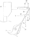
図10は本発明による着席式頸椎牽引装置の第四実施形態の模式図である。
図に示す通り、本実施形態と第一実施形態との差異は、以下の通りである。
本実施形態のオーバーハング部材20の様式は、第一実施形態とは異なり、本実施形態のオーバーハング部材20の一端は、引っ張りモジュール10に設置され、オーバーハング部材20の反対端は、軸部材210に通して設置される。
牽引ロープ30の一端は、引っ張りモジュール10の内部に設置され、その反対端は、オーバーハング部材20の内部より外へと延伸し、軸部材210を巡って設置された後、牽引部材33下方へと垂れ下がる。
このように本実施形態は、別種の着席式頸椎牽引装置1を提供する。
FIG. 10 is a schematic view of a fourth embodiment of a seated cervical traction device according to the present invention.
As shown in the figure, the difference between the present embodiment and the first embodiment is as follows.
The mode of the
One end of the
Thus, the present embodiment provides another type of seated
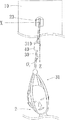
図11は本発明による着席式頸椎牽引装置の第五実施形態の模式図である。
図に示す通り、本実施形態と第四実施形態との差異は、以下の通りである。
本実施形態の牽引ヘッドギア31の構造は、前記とは異なり、牽引ヘッドギア31はさらに、牽引サポートフレーム315を有する。
牽引サポートフレーム315は、固定部材311の下に設置され、少なくとも1個の環状ベルト312は、牽引サポートフレーム315の下方に掛けて設置される。
本実施形態において、牽引サポートフレーム315は硬体構造で、これにより引っ張りモジュール10は、牽引ロープ30を通して、頭部を引っ張りホールドする時、牽引サポートフレーム315の構造による引っ張りとホールドの下、2個の環状ベルト312が牽引する角度は、プレ設定の牽引角度310に近くなる。
さらに、本実施形態では、感知モジュール40を牽引サポートフレーム315に設置し、それが感知する牽引角度310は、実際に牽引し引っ張りホールドする牽引角度310に近くなる。
FIG. 11 is a schematic view of a fifth embodiment of a seated cervical traction device according to the present invention.
As shown in the figure, the difference between the present embodiment and the fourth embodiment is as follows.
The structure of the
The
In the present embodiment, the
Further, in the present embodiment, the
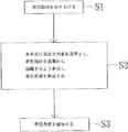
本発明による着席式頸椎牽引装置のステップのフローチャートである図12に示す通り、本実施形態による着席式頸椎牽引の角度感知方法の第一ステップS1では、牽引部材33を吊り下げる。
第二ステップS2では、水平面に垂直な角度を基準とし、牽引部材33を基準から偏離するよう牽引し、牽引角度310を形成する。
第三ステップS3では、牽引角度310を感知する。
上述のステップにおいて、第二ステップではさらに、牽引角度310、及び牽引を感知する牽引部材33の牽引圧力Pを保存する。
第三ステップではさらに、牽引角度310がプレ設定角度範囲より大きいか小さいと、アラーム音を発する。
本実施形態では、着席式頸椎牽引装置1を使用し、上述の方法を行う。
As shown in FIG. 12, which is a flowchart of the steps of the seated cervical traction device according to the present invention, in the first step S1 of the angle sensing method of the seated cervical traction according to the present embodiment, the
In the second step S <b> 2, the pulling
In the third step S3, the pulling
In the above step, the second step further stores the
In the third step, an alarm sound is further generated when the
In the present embodiment, the above-described method is performed using the seated
上記を総合すると、本発明による着席式頸椎牽引装置及びその角度感知方法は、感知モジュールを、オーバーハング部材の一端が下方へと垂れ下がる牽引部材のロープセクションに設置することを利用する。
牽引部材を牽引し、使用者の頭部を引っ張ってホールドすると、オーバーハング部材の一端点は下方へと延伸し、水平面に垂直な角度を基準とし、牽引部材はこの基準に対して牽引角度を偏移し、感知モジュールは、牽引角度の変化を感知する。
こうして、操作者或いは使用者は、着席式頸椎牽引装置の使用者に対する牽引角度を、即時にしかも明確に知ることができ、対応する調整を適時に行うことができ、こうして最良の治療手段と効果を提供することができる。
さらに、圧力感知ユニットを提供し、牽引圧力を探知できる。
また、ストレージユニットを提供し、牽引角度と牽引圧力の数値を保存できる。
表示ユニットは、牽引角度と牽引圧力の数値を表示する。
アラームユニットは、使用者或いは操作者に、牽引角度が、プレ設定角度範囲より大きいか小さい、或いは牽引圧力の数値がプレ設定圧力範囲より大きいか小さいと知らせることができる。
In summary, the seated cervical traction device and its angle sensing method according to the present invention utilizes the installation of the sensing module in the rope section of the traction member where one end of the overhang member hangs downward.
When the pulling member is pulled and the user's head is pulled and held, one end point of the overhanging member extends downward, and the pulling member has a pulling angle with respect to this reference. Shifted, the sensing module senses a change in traction angle.
Thus, the operator or user can immediately and clearly know the traction angle for the user of the seated cervical traction device and can make the corresponding adjustments in a timely manner, so that the best treatment means and effects are achieved. Can be provided.
In addition, a pressure sensing unit can be provided to detect traction pressure.
Also, a storage unit can be provided to store the traction angle and traction pressure values.
The display unit displays numerical values of the traction angle and the traction pressure.
The alarm unit can inform the user or operator that the traction angle is larger or smaller than the preset angle range, or that the numeric value of the traction pressure is larger or smaller than the preset pressure range.
前述した本発明の実施形態は本発明を限定するものではなく、よって、本発明により保護される範囲は後述される特許請求の範囲を基準とする。 The embodiments of the present invention described above do not limit the present invention, and therefore the scope protected by the present invention is based on the claims described below.
1 着席式頸椎牽引装置
2 頭部
10 引っ張りモジュール
100 シート
101 バックレスト
20 オーバーハング部材
21 棒部材
211 第一棒体
212 第二棒体
23 車輪軸
30 牽引ロープ
31 牽引ヘッドギア
33 牽引部材
310 牽引角度
311 固定部材
312 環状ベルト
313 第一環状ベルト
314 第二環状ベルト
315 牽引サポートフレーム
40 感知モジュール
400 感知シグナル
41 ストレージユニット
43 表示ユニット
45 アラームユニット
50 圧力感知モジュール
500 圧力感知シグナル
θ1 第一角度
θ2 第二角度
θ3 第三角度
θ4 轉動角度
P 牽引圧力
DESCRIPTION OF
よって現在では、大多数は機械による頸椎牽引を治療手段としている。
機械牽引は頸椎退化性関節炎(頸椎骨棘)或いはつい間板ヘルニアに常用される。
神経根圧迫を併発する病人に対する機械式頸椎牽引は現在臨床上では、頸肩疼痛に対する主要な保守治療方式である。
頸椎牽引は、着席式と臥式の2種に分けられる。
前者はスペースを節減でき、後者は患者が比較的楽である。
但し、後者に使用する必要な牽引力は比較的大きく、身体とベッドとの間の抵抗を克服しなければならない。
現在では主に着席式頸椎牽引が主流である。
その中で、着席式牽引は、牽引過程において、角度の偏移、或いは牽引圧力のコントロール不適当等の状況が発生しやすい。
牽引角度の偏移或いは牽引圧力の不適当は、治療効果に対して悪影響を及ぼし、治療の効果を低下させてしまう。
よって、これら要因をいかにして抑えるかは、非常に重要である。
Thus, the majority now uses mechanical cervical traction as a treatment.
Mechanical traction is routinely used for cervical degenerative arthritis (cervical spine) or disc herniation.
Mechanical cervical traction for patients with concurrent nerve root compression is currently the main conservative treatment for cervical shoulder pain.
Cervical traction can be divided into two types: seated type and saddle type.
The former can save space and the latter is relatively easy for the patient.
However, the required pulling force to be used in the latter relatively large, has to overcome the resistance between the body and the bed.
Mainly sit-down cervical traction is the mainstream in the current.
Among them, the seated traction tends to cause a situation such as an angle shift or inappropriate control of the traction pressure in the traction process.
The deviation of the pulling angle or the inappropriate pulling pressure adversely affects the therapeutic effect and reduces the therapeutic effect.
Therefore, how to suppress these factors is very important.
Claims (16)
前記オーバーハング部材は、前記引っ張りモジュールの片側に設置され、
前記牽引部材の一端は、前記引っ張りモジュールに連接され、反対端は、前記オーバーハング部材の一端を通して下方へと垂れ下がり、
前記感知モジュールは、前記オーバーハング部材の一端を通して下方へと垂れ下がる牽引部材の一部に設置され、前記オーバーハング部材の一端点が下方へと延伸し、水平面に垂直な角度を基準とし、垂れ下がる牽引部材の一部はある牽引角度の偏りを示し、前記感知モジュールにより前記牽引角度を感知することを特徴とする着席式頸椎牽引装置。 A seated cervical traction device having a tension module, an overhang member, a traction member, a sensing module,
The overhang member is installed on one side of the pull module;
One end of the traction member is connected to the pull module, and the opposite end hangs down through one end of the overhang member;
The sensing module is installed in a part of a pulling member that hangs downward through one end of the overhang member, and one point of the overhang member extends downward, and the traction hangs down based on an angle perpendicular to a horizontal plane. A seated cervical traction device characterized in that a part of a member exhibits a certain traction angle bias and the traction angle is sensed by the sensing module.
前記牽引角度が、プレ設定角度範囲より大きいか小さいと、前記アラームユニットは、アラーム音を発することを特徴とする請求項1に記載の着席式頸椎牽引装置。 The seated cervical traction device further comprises an alarm unit, which comprises a preset angle range,
The seated cervical traction device according to claim 1, wherein the alarm unit emits an alarm sound when the traction angle is larger or smaller than a preset angle range.
前記牽引ロープの一端は、前記引っ張りモジュールに連接され、その反対端は、前記牽引ヘッドギアに連接されることを特徴とする請求項1に記載の着席式頸椎牽引装置。 The traction member has a traction rope and a traction headgear,
The seated cervical traction device according to claim 1, wherein one end of the traction rope is connected to the pulling module, and the other end thereof is connected to the traction headgear.
前記固定部材は、前記牽引ロープの反対端に設置され、
前記少なくとも1個の環状ベルトは、前記固定部材に固定されることを特徴とする請求項5に記載の着席式頸椎牽引装置。 The traction headgear has a fixed member and at least one annular belt;
The fixing member is installed at an opposite end of the tow rope;
The seated cervical traction device according to claim 5, wherein the at least one annular belt is fixed to the fixing member.
前記固定部材は、前記牽引ロープの一端に設置され、
前記牽引サポートフレームは、前記固定部材に固定して設置され、
前記少なくとも1個の環状ベルトは、前記牽引サポートフレームに掛けて設置されることを特徴とする請求項5に記載の着席式頸椎牽引装置。 The traction headgear has a fixed member, a traction support frame and at least one annular belt,
The fixing member is installed at one end of the tow rope,
The traction support frame is fixedly installed on the fixing member;
6. The seated cervical traction device according to claim 5, wherein the at least one annular belt is installed on the traction support frame.
牽引部材を吊り下げ、
水平面に垂直な角度を基準とし、牽引部材を基準から偏離するよう牽引し、牽引角度を形成し、牽引角度を感知することを特徴とする着席式頸椎牽引の角度感知方法。 The steps of the angle sensing method of seated cervical traction include:
Suspend the tow member,
An angle sensing method of seated cervical vertebral traction, wherein a traction member is pulled away from the reference with an angle perpendicular to a horizontal plane as a reference, a traction angle is formed, and a traction angle is detected.
Applications Claiming Priority (2)
| Application Number | Priority Date | Filing Date | Title |
|---|---|---|---|
| TW105109141A TWI610668B (en) | 2016-03-24 | 2016-03-24 | Sitting cervical traction device and angle sensing method thereof |
| TW105109141 | 2016-03-24 |
Publications (2)
| Publication Number | Publication Date |
|---|---|
| JP2017170102A true JP2017170102A (en) | 2017-09-28 |
| JP6263571B2 JP6263571B2 (en) | 2018-01-17 |
Family
ID=59971596
Family Applications (1)
| Application Number | Title | Priority Date | Filing Date |
|---|---|---|---|
| JP2016080556A Expired - Fee Related JP6263571B2 (en) | 2016-03-24 | 2016-04-13 | Seated cervical traction device and angle sensing method thereof |
Country Status (2)
| Country | Link |
|---|---|
| JP (1) | JP6263571B2 (en) |
| TW (1) | TWI610668B (en) |
Cited By (5)
| Publication number | Priority date | Publication date | Assignee | Title |
|---|---|---|---|---|
| CN107669388A (en) * | 2017-11-09 | 2018-02-09 | 江苏兴鑫医用设备有限公司 | The portable electronic cervical-vertebra traction machine of wound form |
| CN109730822A (en) * | 2019-01-15 | 2019-05-10 | 卢书峰 | A kind of Orthopedic Clinical hitch frame |
| CN110916873A (en) * | 2019-10-16 | 2020-03-27 | 宁波市鄞州乐可机电科技有限公司 | Device for treating cervical spondylosis |
| CN112245091A (en) * | 2020-10-30 | 2021-01-22 | 宁波大学 | A cervical vertebra rehabilitation training assistant robot and its application method |
| CN119153033A (en) * | 2024-11-21 | 2024-12-17 | 四川大学华西医院 | Cervical vertebra rehabilitation system based on virtual reality |
Families Citing this family (1)
| Publication number | Priority date | Publication date | Assignee | Title |
|---|---|---|---|---|
| KR102567254B1 (en) * | 2021-06-09 | 2023-08-16 | 황지성 | Traction apparatus including headgear |
Citations (7)
| Publication number | Priority date | Publication date | Assignee | Title |
|---|---|---|---|---|
| JPS58171133U (en) * | 1982-05-10 | 1983-11-15 | オ−ジ−技研株式会社 | Cervical oblique traction device |
| JPS59200647A (en) * | 1983-04-26 | 1984-11-14 | オ−ジ−技研株式会社 | Cervical vertebrae traction apparatus |
| JPH063313U (en) * | 1992-05-14 | 1994-01-18 | オージー技研株式会社 | Cervical traction therapy device |
| WO2006006316A1 (en) * | 2004-07-12 | 2006-01-19 | Yuichiro Morisawa | Cervical vertebrae traction brace and cervical vertebrate traction device |
| JP2007313243A (en) * | 2006-05-29 | 2007-12-06 | Og Giken Co Ltd | Angle setting drawing machine |
| JP2013099424A (en) * | 2011-11-08 | 2013-05-23 | Hideo Nakajima | Electric neck traction machine for exerting traction within safety area of 300g or more by using weight, method for adjusting traction angle of electric neck traction machine, and method for turning electric neck traction machine |
| JP2015217231A (en) * | 2014-05-20 | 2015-12-07 | ミナト医科学株式会社 | Cervical traction device |
Family Cites Families (3)
| Publication number | Priority date | Publication date | Assignee | Title |
|---|---|---|---|---|
| US20120245491A1 (en) * | 2011-03-25 | 2012-09-27 | Novel Ergonomics LLC | Posture feedback system and method, detachable traction system, and traction safety belt combination |
| WO2013140406A1 (en) * | 2012-03-20 | 2013-09-26 | Headway Ltd. | A supportive cradle for physiotherapeutic applications |
| CN203988552U (en) * | 2014-08-06 | 2014-12-10 | 南通市第一人民医院 | The controlled axial traction automatic controller of a kind of cervical vertebra |
-
2016
- 2016-03-24 TW TW105109141A patent/TWI610668B/en not_active IP Right Cessation
- 2016-04-13 JP JP2016080556A patent/JP6263571B2/en not_active Expired - Fee Related
Patent Citations (7)
| Publication number | Priority date | Publication date | Assignee | Title |
|---|---|---|---|---|
| JPS58171133U (en) * | 1982-05-10 | 1983-11-15 | オ−ジ−技研株式会社 | Cervical oblique traction device |
| JPS59200647A (en) * | 1983-04-26 | 1984-11-14 | オ−ジ−技研株式会社 | Cervical vertebrae traction apparatus |
| JPH063313U (en) * | 1992-05-14 | 1994-01-18 | オージー技研株式会社 | Cervical traction therapy device |
| WO2006006316A1 (en) * | 2004-07-12 | 2006-01-19 | Yuichiro Morisawa | Cervical vertebrae traction brace and cervical vertebrate traction device |
| JP2007313243A (en) * | 2006-05-29 | 2007-12-06 | Og Giken Co Ltd | Angle setting drawing machine |
| JP2013099424A (en) * | 2011-11-08 | 2013-05-23 | Hideo Nakajima | Electric neck traction machine for exerting traction within safety area of 300g or more by using weight, method for adjusting traction angle of electric neck traction machine, and method for turning electric neck traction machine |
| JP2015217231A (en) * | 2014-05-20 | 2015-12-07 | ミナト医科学株式会社 | Cervical traction device |
Cited By (7)
| Publication number | Priority date | Publication date | Assignee | Title |
|---|---|---|---|---|
| CN107669388A (en) * | 2017-11-09 | 2018-02-09 | 江苏兴鑫医用设备有限公司 | The portable electronic cervical-vertebra traction machine of wound form |
| CN107669388B (en) * | 2017-11-09 | 2024-01-02 | 江苏兴鑫医用设备有限公司 | Portable winding type electric cervical vertebra tractor |
| CN109730822A (en) * | 2019-01-15 | 2019-05-10 | 卢书峰 | A kind of Orthopedic Clinical hitch frame |
| CN110916873A (en) * | 2019-10-16 | 2020-03-27 | 宁波市鄞州乐可机电科技有限公司 | Device for treating cervical spondylosis |
| CN112245091A (en) * | 2020-10-30 | 2021-01-22 | 宁波大学 | A cervical vertebra rehabilitation training assistant robot and its application method |
| CN112245091B (en) * | 2020-10-30 | 2023-09-05 | 宁波大学 | Cervical vertebra rehabilitation training auxiliary robot and application method thereof |
| CN119153033A (en) * | 2024-11-21 | 2024-12-17 | 四川大学华西医院 | Cervical vertebra rehabilitation system based on virtual reality |
Also Published As
| Publication number | Publication date |
|---|---|
| TWI610668B (en) | 2018-01-11 |
| TW201733536A (en) | 2017-10-01 |
| JP6263571B2 (en) | 2018-01-17 |
Similar Documents
| Publication | Publication Date | Title |
|---|---|---|
| JP6263571B2 (en) | Seated cervical traction device and angle sensing method thereof | |
| US11273344B2 (en) | Multimodal sensory feedback system and method for treatment and assessment of disequilibrium, balance and motion disorders | |
| US10966606B1 (en) | System and method for measuring the head position and postural sway of a subject | |
| KR101183580B1 (en) | Wearable posture correction equipment linking with smart apparatus | |
| US11497433B2 (en) | Balance compensating device, body center measuring apparatus, balance compensation system, and balance compensation method | |
| US20180263530A1 (en) | Chest measuring device, scoliosis correction system, system for remotely diagnosing spine, and wearable measuring device | |
| JP7149848B2 (en) | Therapeutic and physical training devices | |
| US10258259B1 (en) | Multimodal sensory feedback system and method for treatment and assessment of disequilibrium, balance and motion disorders | |
| US9149222B1 (en) | Enhanced system and method for assessment of disequilibrium, balance and motion disorders | |
| US9526946B1 (en) | Enhanced system and method for vibrotactile guided therapy | |
| CN107072543B (en) | Posture correction device, system and method | |
| JP4471588B2 (en) | Equilibrium sensory function diagnostic system and apparatus used therefor | |
| US20160146848A1 (en) | Subject monitor | |
| Goebel et al. | Effectiveness of head-mounted vibrotactile stimulation in subjects with bilateral vestibular loss: a phase 1 clinical trial | |
| JP7011614B2 (en) | A system for displaying the graphic of actual moving dynamic breathing and the graphic of optimal moving dynamic breathing side by side. | |
| KR101623049B1 (en) | Cervical brace and exercise medical therapy apparatus based on smart-phone | |
| US20170215769A1 (en) | Apparatus and a method for detecting the posture of the anatomy of a person | |
| Rodriguez et al. | Wearable postural control system for low back pain therapy | |
| CN206792411U (en) | The dynamic degree monitoring system of neck | |
| JP6342440B2 (en) | Eye movement detection device, eye movement detection method, and eyewear | |
| KR20160043741A (en) | Apparatus for correcting neck posture | |
| KR20190018265A (en) | Device, system and method for posture monitoring | |
| US20230043160A1 (en) | Balance compensating device, body center measuring apparatus, balance compensation system, and balance compensation method | |
| JP2019159335A (en) | Wearable device and display method | |
| KR102544231B1 (en) | Dynamic spinal orthosis |
Legal Events
| Date | Code | Title | Description |
|---|---|---|---|
| A02 | Decision of refusal |
Free format text: JAPANESE INTERMEDIATE CODE: A02 Effective date: 20170411 |
|
| A521 | Written amendment |
Free format text: JAPANESE INTERMEDIATE CODE: A523 Effective date: 20170814 |
|
| A521 | Written amendment |
Free format text: JAPANESE INTERMEDIATE CODE: A821 Effective date: 20170816 |
|
| A521 | Written amendment |
Free format text: JAPANESE INTERMEDIATE CODE: A523 Effective date: 20171016 |
|
| A911 | Transfer to examiner for re-examination before appeal (zenchi) |
Free format text: JAPANESE INTERMEDIATE CODE: A911 Effective date: 20171106 |
|
| TRDD | Decision of grant or rejection written | ||
| A01 | Written decision to grant a patent or to grant a registration (utility model) |
Free format text: JAPANESE INTERMEDIATE CODE: A01 Effective date: 20171121 |
|
| A61 | First payment of annual fees (during grant procedure) |
Free format text: JAPANESE INTERMEDIATE CODE: A61 Effective date: 20171218 |
|
| R150 | Certificate of patent or registration of utility model |
Ref document number: 6263571 Country of ref document: JP Free format text: JAPANESE INTERMEDIATE CODE: R150 |
|
| LAPS | Cancellation because of no payment of annual fees |