JP2017173364A - Fixing apparatus and image forming apparatus - Google Patents
Fixing apparatus and image forming apparatus Download PDFInfo
- Publication number
- JP2017173364A JP2017173364A JP2016055951A JP2016055951A JP2017173364A JP 2017173364 A JP2017173364 A JP 2017173364A JP 2016055951 A JP2016055951 A JP 2016055951A JP 2016055951 A JP2016055951 A JP 2016055951A JP 2017173364 A JP2017173364 A JP 2017173364A
- Authority
- JP
- Japan
- Prior art keywords
- fixing
- fixing belt
- nip
- belt
- fixing device
- Prior art date
- Legal status (The legal status is an assumption and is not a legal conclusion. Google has not performed a legal analysis and makes no representation as to the accuracy of the status listed.)
- Granted
Links
Images





Classifications
-
- G—PHYSICS
- G03—PHOTOGRAPHY; CINEMATOGRAPHY; ANALOGOUS TECHNIQUES USING WAVES OTHER THAN OPTICAL WAVES; ELECTROGRAPHY; HOLOGRAPHY
- G03G—ELECTROGRAPHY; ELECTROPHOTOGRAPHY; MAGNETOGRAPHY
- G03G15/00—Apparatus for electrographic processes using a charge pattern
- G03G15/20—Apparatus for electrographic processes using a charge pattern for fixing, e.g. by using heat
- G03G15/2003—Apparatus for electrographic processes using a charge pattern for fixing, e.g. by using heat using heat
- G03G15/2014—Apparatus for electrographic processes using a charge pattern for fixing, e.g. by using heat using heat using contact heat
- G03G15/2017—Structural details of the fixing unit in general, e.g. cooling means, heat shielding means
- G03G15/2028—Structural details of the fixing unit in general, e.g. cooling means, heat shielding means with means for handling the copy material in the fixing nip, e.g. introduction guides, stripping means
-
- G—PHYSICS
- G03—PHOTOGRAPHY; CINEMATOGRAPHY; ANALOGOUS TECHNIQUES USING WAVES OTHER THAN OPTICAL WAVES; ELECTROGRAPHY; HOLOGRAPHY
- G03G—ELECTROGRAPHY; ELECTROPHOTOGRAPHY; MAGNETOGRAPHY
- G03G15/00—Apparatus for electrographic processes using a charge pattern
- G03G15/20—Apparatus for electrographic processes using a charge pattern for fixing, e.g. by using heat
- G03G15/2003—Apparatus for electrographic processes using a charge pattern for fixing, e.g. by using heat using heat
- G03G15/2014—Apparatus for electrographic processes using a charge pattern for fixing, e.g. by using heat using heat using contact heat
- G03G15/206—Structural details or chemical composition of the pressure elements and layers thereof
-
- G—PHYSICS
- G03—PHOTOGRAPHY; CINEMATOGRAPHY; ANALOGOUS TECHNIQUES USING WAVES OTHER THAN OPTICAL WAVES; ELECTROGRAPHY; HOLOGRAPHY
- G03G—ELECTROGRAPHY; ELECTROPHOTOGRAPHY; MAGNETOGRAPHY
- G03G2215/00—Apparatus for electrophotographic processes
- G03G2215/20—Details of the fixing device or porcess
- G03G2215/2003—Structural features of the fixing device
- G03G2215/2016—Heating belt
- G03G2215/2025—Heating belt the fixing nip having a rotating belt support member opposing a pressure member
- G03G2215/2029—Heating belt the fixing nip having a rotating belt support member opposing a pressure member the belt further entrained around one or more stationary belt support members, the latter not being a cooling device
-
- G—PHYSICS
- G03—PHOTOGRAPHY; CINEMATOGRAPHY; ANALOGOUS TECHNIQUES USING WAVES OTHER THAN OPTICAL WAVES; ELECTROGRAPHY; HOLOGRAPHY
- G03G—ELECTROGRAPHY; ELECTROPHOTOGRAPHY; MAGNETOGRAPHY
- G03G2215/00—Apparatus for electrophotographic processes
- G03G2215/20—Details of the fixing device or porcess
- G03G2215/2003—Structural features of the fixing device
- G03G2215/2016—Heating belt
- G03G2215/2025—Heating belt the fixing nip having a rotating belt support member opposing a pressure member
- G03G2215/2032—Heating belt the fixing nip having a rotating belt support member opposing a pressure member the belt further entrained around additional rotating belt support members
Landscapes
- Physics & Mathematics (AREA)
- General Physics & Mathematics (AREA)
- Fixing For Electrophotography (AREA)
Abstract
Description
本発明は、定着装置および画像形成装置に関するものである。 The present invention relates to a fixing device and an image forming apparatus.
電子写真技術を用いた複写機、ファクシミリ、プリンタ等の画像形成装置においては、用紙等の記録媒体上に作像された未定着のトナー像を記録媒体上に定着する定着装置を備えている。この定着装置としては、例えば、ヒータ等の加熱手段により加熱されるとともに複数の張架部材に張架された定着ベルトを備えている。この定着ベルトと、張架部材のひとつである定着ローラ等のニップ形成部材に定着ベルトを介して圧接しながら回転する加圧ローラ等の加圧部材とで定着ニップなどのニップを形成する。このニップに、トナー像を担持した記録媒体を通過させてトナー像を記録媒体に定着する方式が知られている。 2. Description of the Related Art Image forming apparatuses such as copying machines, facsimile machines, and printers using electrophotographic technology are provided with a fixing device that fixes an unfixed toner image formed on a recording medium such as paper on the recording medium. The fixing device includes, for example, a fixing belt that is heated by a heating unit such as a heater and is stretched around a plurality of stretching members. A nip such as a fixing nip is formed by the fixing belt and a pressure member such as a pressure roller that rotates while being pressed against a nip forming member such as a fixing roller, which is one of the stretching members, via the fixing belt. A system is known in which a recording medium carrying a toner image is passed through the nip to fix the toner image on the recording medium.
特許文献1には、上記定着装置として、ニップを通過した記録媒体を定着ベルトから分離させるための分離機構を備えた定着装置が記載されている。具体的には、前記ニップよりも記録媒体搬送方向下流側で、先端を定着ベルトの外周面に対して所定の隙間を有して対向する分離爪を有している。また、前記定着ベルトの内周面に当接して、前記定着ベルトの前記分離爪と対向する部分の曲率を大きく(曲率半径を小さく)する分離部材を有している。この分離部材は、定着ベルトを介しての加圧部材から離間する位置に配置されている。 Japanese Patent Application Laid-Open No. 2004-151858 describes a fixing device provided with a separation mechanism for separating the recording medium that has passed through the nip from the fixing belt as the fixing device. Specifically, it has a separation claw that faces the outer peripheral surface of the fixing belt with a predetermined gap on the downstream side of the nip in the recording medium conveyance direction. In addition, a separation member that abuts on the inner peripheral surface of the fixing belt and increases the curvature of the portion of the fixing belt facing the separation claw (decreasing the curvature radius) is provided. The separation member is disposed at a position away from the pressure member via the fixing belt.
しかしながら、特許文献1に記載の定着装置においては、定着ニップ通過後の記録媒体にスジ状のしわが生じる不具合があった。
However, the fixing device described in
上記課題を解決するために、本発明は、複数の張架部材に張架される無端状の定着ベルトと、前記複数の張架部材のうちのひとつであるニップ形成部材と、前記ニップ形成部材に対向し、前記定着ベルトを介してニップを形成する加圧部材と、前記定着ベルトを加熱する熱源と、前記ニップ形成部材よりも前記定着ベルト移動方向下流側で、前記定着ベルトを介して前記加圧部材から離間した位置に配置され、前記定着ベルトを張架する分離部材とを備えた定着装置において、前記ニップの出口から前記分離部材の前記定着ベルト移動方向上流側端部までの間に、前記定着ベルトの内周面に当接して前記定着ベルトを押さえる押さえ部材を設けたことを特徴とするものである。 In order to solve the above problems, the present invention provides an endless fixing belt that is stretched around a plurality of stretching members, a nip forming member that is one of the plurality of stretching members, and the nip forming member. A pressure member that forms a nip via the fixing belt, a heat source that heats the fixing belt, and the downstream of the nip forming member in the movement direction of the fixing belt, the A fixing device that is disposed at a position spaced apart from the pressure member and includes a separation member that stretches the fixing belt, between the outlet of the nip and the upstream end of the separation member in the movement direction of the fixing belt. A pressing member that presses the fixing belt in contact with the inner peripheral surface of the fixing belt is provided.
本発明によれば、定着ニップ通過後の記録媒体にスジ状のしわが生じるのを抑制することができる。 According to the present invention, it is possible to suppress the occurrence of streak-like wrinkles on the recording medium after passing through the fixing nip.
以下、本発明を適用した画像形成装置として、電子写真方式のプリンタの一実施形態について説明する。
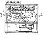
図1は、実施形態に係るプリンタを示す概略構成図である。同図において、このプリンタは、イエロー(Y),マゼンタ(M),シアン(C),ブラック(K)のトナー像を作像するための4つの作像ユニット2Y,2M,2C,2Kを備えている。そして、それら4つの作像ユニット2Y,2M,2C,2Kを、後述する像担持ベルトとしての中間転写ベルト61に対してその無端移動方向に沿って並べたいわゆるタンデム型の構成になっている。
An embodiment of an electrophotographic printer will be described below as an image forming apparatus to which the present invention is applied.
FIG. 1 is a schematic configuration diagram illustrating a printer according to an embodiment. In this figure, the printer includes four image forming units 2Y, 2M, 2C, and 2K for forming yellow (Y), magenta (M), cyan (C), and black (K) toner images. ing. The four image forming units 2Y, 2M, 2C, and 2K have a so-called tandem configuration in which an intermediate transfer belt 61 as an image bearing belt described later is arranged along the endless movement direction.
このプリンタは、給紙路30、転写前搬送路31、手差し給紙路32、手差しトレイ33、レジストローラ対34、搬送ベルトユニット35、定着装置40、搬送切替装置50、排紙路51、排紙ローラ対52、排紙トレイ53等も備えている。更には、2つの光書込ユニット1YM、1CK、一次転写ユニット60、二次転写ユニット78、第1給紙カセット101、第2給紙カセット102等も備えている。
The printer includes a paper feed path 30, a pre-transfer conveyance path 31, a manual paper feed path 32, a manual feed tray 33, a registration roller pair 34, a conveyance belt unit 35, a
作像ユニット2Y,2M,2C,2Kは、潜像担持体たるドラム状の感光体3Y,3M,3C,3Kを有している。また、第1給紙カセット101,第2給紙カセット102は、それぞれ内部に記録シートPの束を収容している。そして、給送ローラ101a,102aの回転駆動により、シート束における一番上の記録シートPを給紙路30に向けて送り出す。
The image forming units 2Y, 2M, 2C, and 2K have drum-shaped photoconductors 3Y, 3M, 3C, and 3K that are latent image carriers. Each of the first
プリンタ筺体における側面には、手差しトレイ33が筺体に対して開閉可能に配設されており、筺体に対して開いた状態でトレイ上面にシート束が手差しされる。手差しされたシート束における一番上の記録シートPは、手差しトレイ33の送出ローラによって給紙路30に向けて送り出される。 A manual feed tray 33 is disposed on the side surface of the printer housing so as to be openable and closable with respect to the housing, and a sheet bundle is manually fed to the upper surface of the tray while being opened with respect to the housing. The uppermost recording sheet P in the manually fed sheet bundle is sent out toward the paper feed path 30 by the feed roller of the manual feed tray 33.
2つの光書込ユニット1YM,1CKは、それぞれ、レーザーダイオード、ポリゴンミラー、各種レンズなどを有している。そして、プリンタ外部のスキャナによって読み取られた画像情報や、パーソナルコンピュータから送られてくる画像情報に基づいて、レーザーダイオードを駆動して、作像ユニット2Y,2M,2C,2Kの感光体3Y,3M,3C,3Kを光走査する。具体的には、作像ユニット2Y,2M,2C,2Kの感光体3Y,3M,3C,3Kは、駆動手段によってそれぞれ図中反時計回り方向に回転駆動せしめられる。光書込ユニット1YMは、駆動中の感光体3Y,3Mに対して、レーザー光をそれぞれ回転軸線方向に偏向せしめながら照射することで、光走査処理を行う。これにより、感光体3Y,3Mには、Y,M画像情報に基づいた静電潜像が形成される。また、光書込ユニット1CKは、駆動中の感光体3C,3Kに対して、レーザー光をそれぞれ回転軸線方向に偏向せしめながら照射することで、光走査処理を行う。これにより、感光体3C,3Kには、C,K画像情報に基づいた静電潜像が形成される。 The two optical writing units 1YM and 1CK each have a laser diode, a polygon mirror, various lenses, and the like. Then, based on image information read by a scanner outside the printer or image information sent from a personal computer, the laser diode is driven, and the photoreceptors 3Y, 3M of the image forming units 2Y, 2M, 2C, 2K. , 3C, 3K are optically scanned. Specifically, the photoreceptors 3Y, 3M, 3C, and 3K of the image forming units 2Y, 2M, 2C, and 2K are rotationally driven in the counterclockwise direction in the drawing by the driving unit. The optical writing unit 1YM performs an optical scanning process by irradiating the driven photoconductors 3Y and 3M while deflecting laser light in the direction of the rotation axis. Thereby, electrostatic latent images based on the Y and M image information are formed on the photoreceptors 3Y and 3M. Further, the optical writing unit 1CK performs an optical scanning process by irradiating the driven photoconductors 3C and 3K while deflecting laser light in the rotation axis direction. Thereby, electrostatic latent images based on the C and K image information are formed on the photoreceptors 3C and 3K.
作像ユニット2Y,2M,2C,2Kは、それぞれ、潜像担持体たる感光体3Y,3M,3C,3Kと、その周囲に配設される各種機器とを1つのユニットとして共通の支持体に支持した状態で、それらがプリンタ筐体に対して一体的に着脱されるものである。それら作像ユニットは、互いに使用するトナーの色が異なる点の他は同様の構成になっている。Y用の作像ユニット2Yを例にすると、これは、感光体3Yの他、これの表面に形成された静電潜像をYトナー像に現像するための現像装置4Yを有している。また、回転駆動される感光体3Yの表面に対して一様帯電処理を施す帯電装置5Yや、後述するY用の一次転写ニップを通過した後の感光体3Y表面に付着している転写残トナーをクリーニングするドラムクリーニング装置6Yなども有している。 Each of the image forming units 2Y, 2M, 2C, and 2K serves as a common support using the photosensitive members 3Y, 3M, 3C, and 3K as latent image carriers and various devices arranged around the photosensitive members 3Y, 3M, 3C, and 3K as one unit. In a supported state, they are integrally attached to and detached from the printer casing. These image forming units have the same configuration except that the colors of the toners used are different from each other. Taking the image forming unit 2Y for Y as an example, this has a developing device 4Y for developing an electrostatic latent image formed on the surface of the photoreceptor 3Y into a Y toner image in addition to the photoreceptor 3Y. Further, the transfer residual toner attached to the surface of the photoreceptor 3Y after passing through a primary transfer nip for Y, which will be described later, or a charging device 5Y that uniformly charges the surface of the photoreceptor 3Y that is driven to rotate. A drum cleaning device 6Y is also provided.
感光体3Yは、アルミニウム等の素管に、感光性を有する有機感光材の塗布による感光層を形成したドラム状のものである。ドラム状のものに代えて、無端ベルト状のものを用いてもよい。 The photoreceptor 3Y has a drum shape in which a photosensitive layer is formed on a base tube made of aluminum or the like by applying a photosensitive organic photosensitive material. An endless belt-shaped belt may be used instead of the drum-shaped belt.
現像装置4Yは、非磁性パイプからなる回転可能な現像スリーブと、これの中空内にスリーブと連れ回らないように配設されたマグネットローラとを具備している。そして、マグネットローラの発する磁力によって現像スリーブの表面に担持した磁性キャリアと非磁性のYトナーとを含有する二成分現像剤(以下、単に現像剤という)により、感光体3Y上の静電潜像を現像する。この際、現像スリーブに印加される現像バイアスと、感光体3Y上の静電潜像との電位差により、現像スリーブ上で静電潜像に対向するYトナーに対して現像ポテンシャルを作用させる。これに対し、現像バイアスと、感光体3Yの地肌部との電位差により、現像スリーブ上で感光体3Yの地肌部に対向するYトナーに対して地肌ポテンシャルを作用させる。それらのポテンシャルにより、現像スリーブ上のYトナーを感光体3Yの静電潜像と地肌部とのうち、静電潜像だけに選択的に付着させて、静電潜像を現像する。 The developing device 4Y includes a rotatable developing sleeve made of a non-magnetic pipe, and a magnet roller disposed in the hollow so as not to rotate with the sleeve. Then, an electrostatic latent image on the photoreceptor 3Y is obtained by a two-component developer (hereinafter simply referred to as a developer) containing a magnetic carrier carried on the surface of the developing sleeve by the magnetic force generated by the magnet roller and non-magnetic Y toner. Develop. At this time, the developing potential is applied to the Y toner facing the electrostatic latent image on the developing sleeve by the potential difference between the developing bias applied to the developing sleeve and the electrostatic latent image on the photoreceptor 3Y. On the other hand, the background potential is applied to the Y toner facing the background portion of the photoreceptor 3Y on the developing sleeve due to the potential difference between the developing bias and the background portion of the photoreceptor 3Y. Due to these potentials, the Y toner on the developing sleeve is selectively attached only to the electrostatic latent image of the electrostatic latent image and the background portion of the photoreceptor 3Y to develop the electrostatic latent image.
現像装置4Yに対しては、Yトナー補給装置により、Yトナーボトル103Y内のYトナーが適宜補給される。現像装置4Y内にはトナー濃度検知手段としてのトナー濃度センサが設けられている。トナー濃度センサは磁性体であるキャリアに起因する現像剤の透磁率を検出するものである。後述するメイン制御部は、このトナー濃度センサからの出力値と、トナー濃度目標値であるセンサからの出力目標値との比較に基づいて、Yトナー補給装置の駆動を制御することで、現像剤のトナー濃度を一定範囲内(例えば4wt%〜9wt%)にしている。現像装置4M,4C,4Kついても、同様のトナー補給制御を行う。 The Y toner in the Y toner bottle 103Y is appropriately supplied to the developing device 4Y by the Y toner supply device. In the developing device 4Y, a toner concentration sensor is provided as a toner concentration detecting means. The toner concentration sensor detects the magnetic permeability of the developer caused by the carrier that is a magnetic material. The main control unit, which will be described later, controls the driving of the Y toner replenishing device based on the comparison between the output value from the toner density sensor and the output target value from the sensor that is the toner density target value, thereby developing the developer. Is set within a certain range (for example, 4 wt% to 9 wt%). The same toner replenishment control is performed for the developing devices 4M, 4C, and 4K.
ドラムクリーニング装置6Yは、感光体3Yに当接させたポリウレタンゴム製のクリーニングブレードによって感光体3Yの表面から転写残トナーを掻き取る方式のものである。かかる方式のものに代えて、他の方式のものを用いてもよい。クリーニング性を高める目的で、ドラムクリーニング装置6Yは、クリーニングブレードに加えて、回転自在なファーブラシも感光体3Yに当接させている。このファーブラシは、固形潤滑剤から潤滑剤を掻き取って微粉末にしながら感光体3Y表面に塗布する役割も兼ねている。 The drum cleaning device 6Y is of a type that scrapes off transfer residual toner from the surface of the photoreceptor 3Y by a polyurethane rubber cleaning blade in contact with the photoreceptor 3Y. Instead of this method, another method may be used. In order to improve the cleaning property, the drum cleaning device 6Y has a rotatable fur brush in contact with the photosensitive member 3Y in addition to the cleaning blade. This fur brush also serves to apply the lubricant to the surface of the photoreceptor 3Y while scraping the lubricant from the solid lubricant to make a fine powder.
感光体3Yの上方には、除電ランプが配設されており、この除電ランプも作像ユニット2Yの一部になっている。除電ランプは、ドラムクリーニング装置6Yを通過した後の感光体3Y表面を光照射によって除電する。除電された感光体3Yの表面は、帯電装置5Yによって一様に帯電せしめられた後、上述した光書込ユニット1YMによる光走査が施される。なお、帯電装置5Yは、電源から帯電バイアスの供給を受けながら回転駆動するものである。かかる方式のものに代えて、感光体3Yに対して非接触で帯電処理を行うスコロトロンチャージャ方式のものを採用してもよい。 A static elimination lamp is disposed above the photoreceptor 3Y, and this static elimination lamp is also a part of the image forming unit 2Y. The neutralization lamp neutralizes the surface of the photoreceptor 3Y after passing through the drum cleaning device 6Y by light irradiation. The surface of the photoreceptor 3Y that has been neutralized is uniformly charged by the charging device 5Y, and then subjected to optical scanning by the optical writing unit 1YM described above. The charging device 5Y is driven to rotate while receiving a charging bias from a power source. Instead of such a system, a scorotron charger system that performs a non-contact charging process on the photoreceptor 3Y may be employed.
Y用の作像ユニット2Yについて説明したが、M,C,K用の作像ユニット2M,2C,2Kも、Y用の作像ユニット2Yと同様の構成になっている。 The image forming unit 2Y for Y has been described, but the image forming units 2M, 2C, and 2K for M, C, and K have the same configuration as the image forming unit 2Y for Y.
4つの作像ユニット2Y,2M,2C,2Kの下方には、一次転写ユニット60が配設されている。この一次転写ユニット60は、複数のローラによって張架している像担持体たる中間転写ベルト61を、感光体3Y,3M,3C,3Kに当接させながら、何れか1つのローラの回転駆動によって図中時計回り方向に無端移動させる。これにより、感光体3Y,3M,3C,3Kと中間転写ベルト61とが当接するY,M,C,K用の一次転写ニップが形成されている。 A primary transfer unit 60 is disposed below the four image forming units 2Y, 2M, 2C, and 2K. The primary transfer unit 60 is driven by the rotational drive of any one of the rollers while bringing the intermediate transfer belt 61, which is an image carrier stretched by a plurality of rollers, into contact with the photoreceptors 3Y, 3M, 3C, 3K. It is moved endlessly in the clockwise direction in the figure. As a result, primary transfer nips for Y, M, C, and K in which the photoreceptors 3Y, 3M, 3C, and 3K abut on the intermediate transfer belt 61 are formed.
Y,M,C,K用の一次転写ニップの近傍では、ベルトループ内側に配設された一次転写ローラ62Y,62M,62C,62Kによって中間転写ベルト61を感光体3Y,3M,3C,3Kに向けて押圧している。これら一次転写ローラ62Y,62M,62C,62Kには、それぞれ一次転写電源によって一次転写バイアスが印加されている。これにより、Y,M,C,K用の一次転写ニップには、感光体3Y,3M,3C,3K上のトナー像を中間転写ベルト61に向けて静電移動させる一次転写電界が形成されている。 In the vicinity of the primary transfer nips for Y, M, C, and K, the intermediate transfer belt 61 is moved to the photoreceptors 3Y, 3M, 3C, and 3K by primary transfer rollers 62Y, 62M, 62C, and 62K disposed inside the belt loop. It is pushing toward. A primary transfer bias is applied to the primary transfer rollers 62Y, 62M, 62C, and 62K by a primary transfer power source. As a result, a primary transfer electric field for electrostatically moving the toner images on the photoreceptors 3Y, 3M, 3C, and 3K toward the intermediate transfer belt 61 is formed in the primary transfer nips for Y, M, C, and K. Yes.
図中時計回り方向の無端移動に伴ってY,M,C,K用の一次転写ニップを順次通過していく中間転写ベルト61のおもて面には、Yトナー像,Mトナー像,Cトナー像,Kトナー像が順次重ね合わせて一次転写される。この重ね合わせの一次転写により、中間転写ベルト61のおもて面には4色重ね合わせトナー像が形成される。 In the figure, on the front surface of the intermediate transfer belt 61 that sequentially passes through the primary transfer nips for Y, M, C, and K along with the endless movement in the clockwise direction, the Y toner image, the M toner image, and the C The toner image and the K toner image are sequentially superimposed and primarily transferred. By this superimposing primary transfer, a four-color superimposed toner image is formed on the front surface of the intermediate transfer belt 61.
中間転写ベルト61の図中下方には、二次転写ユニット78が配設されている。この二次転写ユニット78は、無端状の二次転写ベルト77、接地従動ローラ72、駆動ローラ、二次ベルトクリーニング装置76、トナー付着量検知センサ64などを有している。二次転写ベルト77は、そのループ内側に配設された接地従動ローラ72と、駆動ローラとによってテンション張架されながら、駆動ローラの回転駆動に伴って図中反時計回り方向に無端移動せしめられる。 A secondary transfer unit 78 is disposed below the intermediate transfer belt 61 in the drawing. The secondary transfer unit 78 includes an endless secondary transfer belt 77, a ground driven roller 72, a driving roller, a secondary belt cleaning device 76, a toner adhesion amount detection sensor 64, and the like. The secondary transfer belt 77 is endlessly moved in the counterclockwise direction in the figure as the driving roller rotates while being tensioned by the ground driven roller 72 disposed inside the loop and the driving roller. .
二次転写ユニット78の二次転写ベルト77は、自らの接地従動ローラ72に対する掛け回し箇所を、一次転写ユニット60の中間転写ベルト61における二次転写バイアスローラ68に対する掛け回し箇所に当接させて二次転写ニップを形成している。中間転写ベルト61のループ内側の二次転写バイアスローラ68には後述する二次転写電源から出力される二次転写バイアスが印加されるのに対し、二次転写ベルト77のループ内側の接地従動ローラ72は接地されている。これにより、二次転写ニップ内に二次転写電界が形成される。 The secondary transfer belt 77 of the secondary transfer unit 78 has its place where the belt is driven with respect to the ground driven roller 72 abutted with the place where the intermediate transfer belt 61 of the primary transfer unit 60 is applied to the secondary transfer bias roller 68. A secondary transfer nip is formed. A secondary transfer bias output from a secondary transfer power source, which will be described later, is applied to a secondary transfer bias roller 68 inside the loop of the intermediate transfer belt 61, whereas a ground driven roller inside the loop of the secondary transfer belt 77. 72 is grounded. As a result, a secondary transfer electric field is formed in the secondary transfer nip.
二次転写ニップの図中右側方には、レジストローラ対34が配設されており、ローラ間に挟み込んだ記録シートPを中間転写ベルト61上の4色重ね合わせトナー像に同期させ得るタイミングで二次転写ニップに送り出す。二次転写ニップ内では、中間転写ベルト61上の4色トナー像が二次転写電界やニップ圧の影響によって記録シートPに一括二次転写され、記録シートPの白色と相まってフルカラー画像となる。 A registration roller pair 34 is disposed on the right side of the secondary transfer nip in the drawing, and the recording sheet P sandwiched between the rollers can be synchronized with the four-color superimposed toner image on the intermediate transfer belt 61. Send to the secondary transfer nip. In the secondary transfer nip, the four-color toner image on the intermediate transfer belt 61 is secondarily transferred onto the recording sheet P under the influence of the secondary transfer electric field and the nip pressure, and becomes a full color image combined with the white color of the recording sheet P.
二次転写ニップを通過した後の中間転写ベルト61のおもて面には、二次転写残トナーが付着している。この二次転写残トナーは、一次転写ユニット60の一次ベルトクリーニング装置75によって中間転写ベルト61の表面から除去される。 The secondary transfer residual toner adheres to the front surface of the intermediate transfer belt 61 after passing through the secondary transfer nip. The secondary transfer residual toner is removed from the surface of the intermediate transfer belt 61 by the primary belt cleaning device 75 of the primary transfer unit 60.
二次転写ニップを通過した記録シートPは、中間転写ベルト61や二次転写ベルト77から離間して、搬送ベルトユニット35に受け渡される。この搬送ベルトユニット35は、無端状の搬送ベルト36を駆動ローラ37と従動ローラ38とによって張架しながら、駆動ローラ37の回転駆動によって図中反時計回り方向に無端移動せしめる。そして、二次転写ニップから受け渡された記録シートPをベルト上部張架面に保持しながら、ベルトの無端移動に伴って搬送して定着装置40に受け渡す。
The recording sheet P that has passed through the secondary transfer nip is separated from the intermediate transfer belt 61 and the secondary transfer belt 77 and transferred to the transport belt unit 35. The conveyor belt unit 35 moves the endless conveyor belt 36 endlessly in the counterclockwise direction in the figure by the rotational driving of the driving roller 37 while being stretched by the driving roller 37 and the driven roller 38. Then, the recording sheet P delivered from the secondary transfer nip is conveyed along with the endless movement of the belt while being held on the belt upper tension surface, and delivered to the fixing
定着装置40内に送られた記録シートPは、無端状の定着ベルトと加圧ローラとの当接による定着ニップに挟み込まれる。そして、加圧や加熱などの作用により、その表面にトナー像が定着せしめられる。
The recording sheet P sent into the fixing
二次転写ニップで第1面にトナー像が転写され、且つ定着装置40でその第1面にトナー像が定着せしめられた記録シートPは、搬送切替装置50に向けて送り出される。本プリンタにおいては、搬送切替装置50、再送路54、スイッチバック路55、スイッチバック後搬送路56等により、再送手段が構成されている。搬送切替装置50は、定着装置40から受け取った記録シートPのその後の搬送先を、排紙路51と、再送路54とで切り替える。
The recording sheet P on which the toner image is transferred to the first surface at the secondary transfer nip and the toner image is fixed on the first surface by the fixing
具体的には、記録シートPの第1面だけに対して画像を形成する片面モードのプリントジョブの実行時には、搬送先を排紙路51に設定する。これにより、第1面だけに画像が形成された記録シートPを、排紙路51経由で排紙ローラ対52に送って、機外の排紙トレイ53上に排紙する。また、記録シートPの両面に対してそれぞれ画像を形成する両面モードのプリントジョブの実行時において、両面にそれぞれ画像が定着された記録シートPを定着装置40から受け取ったときにも、搬送先を排紙路51に設定する。これにより、両面に画像が形成された記録シートPを、機外の排紙トレイ53上に排紙する。
Specifically, when a single-sided mode print job for forming an image only on the first side of the recording sheet P is executed, the conveyance destination is set to the paper discharge path 51. As a result, the recording sheet P on which an image is formed only on the first surface is sent to the
一方、両面モードのプリントジョブの実行時において、第1面だけに画像が定着された記録シートPを定着装置40から受け取ったときには、搬送先を再送路54に設定する。再送路54には、スイッチバック路55が繋がっており、再送路54に送られた記録シートPはこのスイッチバック路55に進入する。そして、記録シートPの搬送方向の全領域がスイッチバック路55に進入すると、記録シートPの搬送方向が逆転されて、記録シートPがスイッチバックする。スイッチバック路55には、再送路54の他に、スイッチバック後搬送路56が繋がっており、スイッチバックした記録シートPは、このスイッチバック後搬送路56に進入する。このとき、記録シートPの上下が反転する。そして、上下反転した記録シートPは、スイッチバック後搬送路56と、上述した給紙路30とを経由して、二次転写ニップに再送される。二次転写ニップで第2面にもトナー像が転写された記録シートPは、定着装置40を経由して第2面にトナー像が定着せしめられた後、搬送切替装置50と、排紙路51と排紙ローラ対52とを経由して、排紙トレイ53上に排紙される。
On the other hand, when a recording sheet P having an image fixed only on the first side is received from the fixing
図2は、定着装置40の概略断面図である。
本実施形態の定着装置40は、ベルト定着方式であり、定着ベルト43と、定着ベルト43に対向して回転可能に設けられた加圧部材としての加圧ローラ45とを備えている。定着ベルト43は、定着ローラ41、加熱ローラ42、テンションローラ47などにより張架されている。定着ローラ41、加圧ローラ45及び加熱ローラ42は、定着装置40の筐体の長手方向に回転可能に軸支されている。
FIG. 2 is a schematic sectional view of the fixing
The fixing
定着ベルト43は、PI(ポリイミド)層で形成される無端ベルトであって、外周表面にPFA(テトラフルオロエチレン・パーフルオロアルキルビニルエーテル共重合体)膜等のオフセット防止剤がコーティングされたものである。定着ローラ41と加圧ローラ45は、ゴムローラであり、加圧ローラ45が定着ベルト43を介して定着ローラ41の中心方向に加圧されることにより、加圧ローラ45と定着ベルト43との間で定着ニップN1が形成される。テンションローラ47は、定着ベルト43にテンションを与えるものであり、円筒形をしたアルミ管で形成される。
The fixing
加圧ローラ45は、定着ベルト43に対して接離可能に設けられており、通紙(定着)の際には、加圧脱圧機構により加圧ローラ45が定着ベルト43を加圧して定着ニップN1を形成する。一方、待機時(非定着時)においては、加圧が解除され、加圧ローラ45が定着ベルト43から離間する。
The
また、加熱ローラ42は、アルミニウム又は鉄製の中空ローラで内部にハロゲンヒータ等のヒータから成る熱源44を有している。熱源44は誘導加熱機構であってもよい。加熱ローラ42と定着ベルト43を介して対抗する位置には、温度センサ素子であるサーミスタ11が配置されており、サーミスタ11の温度検知に基づき、その設定温度となるように熱源44を制御している。
The
また、定着ローラ41には、モータや減速ギヤ列などによって構成された駆動手段が接続されており、この駆動手段により図中矢印方向に回転駆動する。定着ローラの回転により、定着ローラ41に圧接する加圧ローラ45および定着ベルト43が同速で図1に示す矢印方向に回転する。定着ローラ41の回転により、定着ローラ41に圧接する加圧ローラ45および定着ベルト43が同速で図中に示す矢印方向に回転する。また、加圧ローラ45を駆動手段により回転駆動し、これに圧接する定着ベルト43、定着ローラ41を従動回転させてもよい。
The fixing
また、テンションローラ47と加熱ローラ42との間には、定着ベルト43の外周面を研磨する研磨装置10が配設されている。研磨装置10は、定着ベルト43の外周面に当接する研磨ローラ10aと、この研磨ローラ10aと定着ベルト43を介して対向する対向ローラ10bとを備えている。研磨ローラ10aは、加圧スプリング10cにより定着ベルト43に圧接せしめられている。研磨ローラ10aと対向ローラ10bは、定着ベルト43に対して接離可能に設けられており、定着ベルト43を研磨する必要のない時は、研磨ローラ10aおよび対向ローラ10bを定着ベルト43から離間させる。これにより、定着ベルト43の寿命を高めることができる。
Further, between the
記録シートPが、定着ニップN1を通過するときに、記録シートPの裁断バリによって定着ベルト43の表面が摩耗する。そのため、定着ベルト43は、使用頻度の高い記録シートPの幅に対応する箇所の摩耗と、これよりも外側箇所の摩耗とが異なる。その結果、使用頻度の高い記録シートよりも幅の広い記録シートを用いて画像を出力したときに、定着ベルト上の摩耗箇所が画像に現れてしまうという問題がある。本実施形態においては、研磨装置10を設けて、定着ベルト43の外周面を研磨ローラ10aで研磨することで、定着ベルト43の摩耗を、幅方向で均一にし、上記問題の発生を抑制している。
When the recording sheet P passes through the fixing nip N1, the surface of the fixing
また、定着ベルト43の内側であって、定着ニップN1の定着ベルト表面移動方向下流側には、分離部材たる分離補助部材48が設けられている。分離補助部材48は、SUSなどの金属や樹脂などの剛体で形成され、断面が略円弧状のブロック部材である。分離補助部材48は、定着ニップN1の定着ベルト表面移動方向下流側で、定着ベルト43の内周面と接触し、定着ベルト43を定着ローラ41から離間する方向に張架して、定着ベルト43の進行方向を急激に変化させている。定着ベルト43の進行方向を急激に変化させることで、定着ベルト43の曲率を大きく(曲率半径を小さく)でき、記録シートPを、この曲率により分離させることができ、分離性能を向上させることができる。
A
また、本実施形態においては、分離補助部材48の定着ベルト43との接触面を円弧形状としているため定着ベルト43は、この円弧状の接触面に倣ってスムーズに移動させることができる。
In the present embodiment, since the contact surface of the
また、分離補助部材48の定着ローラ41との対向面も円弧形状として、定着ローラ41表面に沿った形状としている。これにより、分離補助部材48が、定着ローラ41と接触することなく、狭いスペースに分離補助部材48を配置することができる。
In addition, the surface of the
分離補助部材48は、定着ローラ41の軸方向全域に亘って設けられており、その両端が、定着装置40の筐体の側面に固定されている。また、分離補助部材48は、加圧ローラ45と接触しない位置に配置されており、加圧ローラ45の耐久性およびモータのトルク上昇を起こさせない構成としている。
The
また、定着ベルト43を介して分離補助部材48と対向するように、第二の分離部材たる分離板46が配設されている。分離板46の先端が、定着ベルト43とで微小隙間を有するように配設されている。分離板46の先端は、先細りとなっており、テーパ状に尖った形状となっている。また、本実施形態においては、定着ニップと分離補助部材48との間で定着ベルト43の内周面に当接し、定着ベルト43を加圧ローラ45に当接させる押さえ部材49が配設されている。
A
以下、本実施形態の定着装置40の基本動作について説明する。
トナー像が形成された記録シートPが、定着ニップN1へ搬送され、記録シート上のトナー像が定着ニップN1で加熱溶融されることによって、トナー像が定着される。その後、記録シートPは、ニップ出口後の分離板46等により記録シートが定着ベルト43から剥離され、定着装置40から排出される。定着装置40の出口部には記録シートPが所定のタイミングで通過していることを確認する為に、排紙センサを配置している。そして、所定のタイミングで記録シートPが排出されないときは、用紙ジャムが発生したとして、ユーザーに報知するなどのジャム処理モードに移行する。
Hereinafter, the basic operation of the fixing
The recording sheet P on which the toner image is formed is conveyed to the fixing nip N1, and the toner image on the recording sheet is heated and melted at the fixing nip N1, whereby the toner image is fixed. Thereafter, the recording sheet P is separated from the fixing
次に、本実施形態の特徴部について説明する。
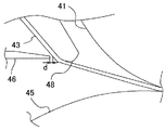
図3は、従来の定着装置の定着ニップN1出口近傍を示す拡大図である。
分離板46は、主に、定着ベルト43の曲率で分離し難い薄紙などのコシの弱い記録シートPの先端を分離板46の先端に当接させて、定着ベルト43から記録シートPを分離させる機能を担うものである。また、分離板46の先端が定着ベルト43に接触すると、定着ベルト43が分離板46により削られ、定着ベルト43の寿命が低下してしまう。このように、分離板46の先端が定着ベルト43に接触せず、かつ、薄紙が確実に分離板46に当接するようにするためには、定着ベルト43と分離板46との隙間d(約0.2mm)を、高精度に管理する必要がある。
Next, the characteristic part of this embodiment is demonstrated.
FIG. 3 is an enlarged view showing the vicinity of the exit of the fixing nip N1 of the conventional fixing device.
The
そこで、定着ベルト43を介して分離板46と対向する分離補助部材48を剛体で形成し分離補助部材48の変形による定着ベルト43と分離板46との隙間dの変動を抑制している。また、剛体の分離補助部材48を、定着ベルト43を介して加圧ローラ45に当接する構成とした場合、分離補助部材48が加圧ローラ45の加圧力で弾性変形し、定着ベルト43と分離板46との隙間dが変動してしまうおそれがある。また、加圧ローラ45の耐久性が低下する課題もある。下記表1に示すように、分離補助部材48を加圧ローラ45から2mm退避させた場合は、加圧ローラ45、定着ベルト43の寿命を約2倍高めることができる。
Therefore, the

しかしながら、分離補助部材48を加圧ローラ45から離間した位置に設けることで、定着ニップN1から分離板46の先端が対向する分離部までの間、定着ベルト43に付着した記録シートPには圧力がかからなくなる。記録シートPは、定着ニップN1において、加熱されることにより、記録シートPに含まれる水分が気化して水蒸気となる。定着ニップN1においては、面圧約40[N/cm2]程度の強い圧力で加圧されているため、記録シートPから水蒸気が放出されることがない。しかし、定着ニップN1を出た記録シートPには圧がなくなるため記録シートPから水蒸気が放出される。
However, by providing the
図3に示すように、定着ニップ出口における定着ベルト43と加圧ローラ45との間の隙間が、定着ベルト43が定着ローラ41に巻きつく場合に比べて狭い。そのため、その狭い領域には熱が篭りやすく、記録シートの温度が低下せず、多くの水蒸気が放出される。水蒸気は、記録シートPの加圧ローラ45と対向する面(裏面)から主に放出される。また、定着ニップN1を出た記録シートは、定着ベルト43に付着した状態で、分離板46の先端が対向する分離部まで搬送される。記録シートPの非画像部は、トナー像が形成された画像部よりも高さが低いため、定着ベルト43と非画像部との間には隙間が生じており、この隙間にも水蒸気が放出される。水蒸気が放出されることにより、記録シートPの繊維が乾燥して縮み波打ちが発生する。
As shown in FIG. 3, the gap between the fixing
また、記録シートPの加圧ローラ45と対向する面(裏面)から主に放出された水蒸気は、この狭い隙間に留まり、再度、記録シートに吸収されて記録シートを濡らす。また、定着ベルト43と非画像部との間に放出された水蒸気もその隙間に留まり、再度、記録シートに吸収されて記録シートを濡らす。記録シートPが濡れることで繊維が延びて記録シートに波打ちが生じてしまう。
Further, water vapor mainly released from the surface (back surface) of the recording sheet P facing the
このように、図3に示す従来構成においては、定着ニップN1から分離板46の先端が対向する分離部まで記録シートPが搬送されるまでの間に、水蒸気の放出による乾燥や、水蒸気の再吸収による濡れにより記録シートPの繊維に伸縮が発生し、この間で記録シートPに波打ちが生じる。そして、波打ちが生じた状態で排紙ローラ対などにより挟まれることにより、図4示すように記録シートPにしわSが生じてしまう。
As described above, in the conventional configuration shown in FIG. 3, during the period from when the recording sheet P is conveyed from the fixing nip N <b> 1 to the separation portion where the leading edge of the
そこで、本実施形態においては、定着ローラ41と分離補助部材48との間で定着ベルト43の内周面に当接し、定着ベルトを押さえる押さえ部材49を設けた。
Therefore, in the present embodiment, a pressing
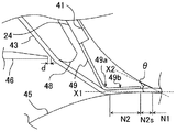
図5は、本実施形態の定着装置の定着ニップN1出口近傍を示す拡大図である。
本実施形態においては、定着ベルト43の内側で、定着ローラ41と分離補助部材48との間に押さえ部材49が配設されている。押さえ部材49は、SUS等の金属で形成された厚さ0.2mm程度の板状部材であり、一端が支持板24に支持されており、この支持板24から加圧ローラ側へ延び、途中で定着ニップN1側に屈曲せしめられた板バネ形状となっている。このように、途中で屈曲させることにより、定着ベルト43の内周面に当接し、定着ベルト43を加圧ローラ45に当接させる押さえ部49bと、押さえ部49bよりも定着ベルト43表面移動方向下流側に位置し、屈曲した剥離部49aとが形成される。
FIG. 5 is an enlarged view showing the vicinity of the exit of the fixing nip N1 of the fixing device of the present embodiment.
In this embodiment, a pressing
押さえ部材49は、加圧ローラ45に対して0.4mm食い込むように設けられ、弾性変形して定着ベルト43を加圧ローラ45に所定の荷重で押圧するように設置している。これにより、押さえ部材49により定着ニップN1の記録シート搬送方向下流側にポストニップ部N2が形成される。
The pressing
また、押さえ部材49の押さえ部49bの形状を、加圧ローラ45の表面形状に沿わせる形状にして、定着ベルト43を加圧ローラ45に均一に押圧している。また、ポストニップ部N2の出口において、定着ベルト43は、押さえ部材49の剥離部49aの屈曲に沿うようにしてその移動方向が、急激に変化せしめられる。これにより、ポストニップ部N2出口における定着ベルト43の曲率を大きく(曲率半径を小さく)できる。本実施形態において、ポストニップ部N2の出口における定着ベルト43の曲率半径がφ6mmとなるように、押さえ部材49の剥離部49aを構成している。
Further, the shape of the
本実施形態においては、定着ニップN1を出た記録シートPは、引き続きポストニップ部N2で圧力を受けながら搬送される。このポストニップ部N2では、定着ニップN1よりも圧力が低いため、このポストニップ部N2で水蒸気が記録シートから放出される。このような記録媒体から水蒸気が放出されることにより、紙の繊維が乾燥して縮もうとするが、記録シートは、定着ベルト43を介して押さえ部材49により加圧ローラに押さえられているため、繊維が縮めず、水蒸気の放出による記録シートの波打ちが抑制される。
In the present embodiment, the recording sheet P that has exited the fixing nip N1 is conveyed while receiving pressure at the post nip portion N2. Since the pressure at the post nip portion N2 is lower than that at the fixing nip N1, water vapor is discharged from the recording sheet at the post nip portion N2. By releasing water vapor from such a recording medium, the fiber of the paper dries and shrinks, but the recording sheet is pressed by the pressing
また、上記ポストニップ部N2で放出された水蒸気は、記録シートPと定着ベルト43などの間で気泡として留まり、再度、記録シートPに吸収され記録シートPを濡らす。しかし、この水蒸気の吸収の際、記録シートPは定着ベルト43を介して押さえ部材49により加圧ローラ45に押さえられている。従って、水蒸気の吸収により濡れて紙の繊維が伸びようとするが、記録シートPは、定着ベルト43を介して押さえ部材49により加圧ローラ45に押さえられているため、繊維が伸びることができず、水蒸気の吸収による記録シートPの波打ちが抑制される。
Further, the water vapor released from the post nip portion N2 remains as bubbles between the recording sheet P and the fixing
このように、記録シートの波打ちが抑制されることにより、定着ニップ通過後の記録シートが、排紙ローラ対により挟まれて搬送されるときに、記録シートに先の図4に示したようなスジ状のしわが生じるのを抑制することができる。 In this way, by suppressing the undulation of the recording sheet, when the recording sheet after passing through the fixing nip is nipped and conveyed by the pair of paper discharge rollers, the recording sheet is as shown in FIG. Generation of streak-like wrinkles can be suppressed.
本実施形態では、水蒸気の放出や吸収で記録シートの繊維が伸縮しないように記録シートを押さえておけばよく、その圧力は、定着ニップの圧力よりも十分低くてよい。本実施形態においては、ポストニップ部N2の圧力は、5[N]程度でよい。また、記録シートに先の図4に示したようなスジ状のしわが生じない程度に記録シートの波打ちを抑制すればよい。そのため、定着ベルト43を加圧ローラに近接するように押さえ部材49で押さえ、定着ベルト43と加圧ローラ45との間に多少の隙間があってもよい。この場合は、ニップN1を出た記録シートPが、水蒸気の放出や吸収で波打ちが生じようとすると加圧ローラ45や定着ベルトに当たり、これ以上波打とうとするのが抑制される。よって、定着ベルト43を加圧ローラに近接するように押さえ部材49で押さえて、定着ベルト43と加圧ローラ45との間に多少の隙間があっても波打ちを抑制できる。また、押さえ部材49で定着ベルト48を加圧ローラ45に当接させない場合において、前述した隙間は記録シートPの厚み分であると、定着ニップN1を出た記録シートは、定着ベルトと加圧ローラとで挟まれる形で搬送されるため、より効果的に、記録シートの波打ちをより効果的に抑制することができる。
In this embodiment, the recording sheet may be pressed so that the fibers of the recording sheet do not expand or contract due to the release or absorption of water vapor, and the pressure may be sufficiently lower than the pressure in the fixing nip. In the present embodiment, the pressure of the post nip portion N2 may be about 5 [N]. Further, the waviness of the recording sheet may be suppressed to such an extent that no streak-like wrinkles as shown in FIG. Therefore, the fixing
また、ポストニップ部N2の出口で、定着ベルト43は、押さえ部材49の剥離部49aの屈曲に沿うようにしてその移動方向が急激に変化せしめられている。その結果、ポストニップ部N2の出口で、記録シートPは、曲率分離により定着ベルト43から分離される。また、薄紙などのコシの弱い記録シートPや、記録シートPの先端部分まで画像が形成された記録シートPは、このポストニップ部N2の出口で曲率分離せず、定着ベルト43に付着した状態で上記分離部へ搬送される。しかし、上記ポストニップ部N2において、定着ニップN1で発生した水蒸気は既に放出されている。従って、上記分離部へ移動するまでの間で、水蒸気が放出されることは、ほぼない。また、ポストニップ部N2の出口の定着ベルト43と加圧ローラ45との間の隙間は、先の図3に比べて広い。従って、熱がこのポストニップ部N2の出口付近に篭らず、周囲に放出されている。よって、上記分離部へ移動するまでの間に、記録シートがポストニップ部N2の出口付近の熱により加熱され、水蒸気を放出することもほぼない。従って、ポストニップ部N2から上記分離部までの間で水蒸気の放出による乾燥で、波打ちが生じることは、ほぼない。
Further, at the exit of the post nip portion N2, the fixing
さらに、ポストニップ部N2で記録シートに再吸収されなかった水蒸気が、ポストニップ部N2の出口で周囲に放出される。しかし、ポストニップ部N2の出口の定着ベルト43と加圧ローラ45との間の隙間は、先の図3に比べて広いため、ポストニップ部N2の出口付近で留まることがない。従って、ポストニップ部N2から上記分離部までの間で、水蒸気の再吸収が生じることもほぼない。従って、ポストニップ部N2から上記分離部までの間で水蒸気の再吸収による濡れで波打ちが生じることは、ほぼない。
Further, water vapor that has not been reabsorbed by the recording sheet at the post nip portion N2 is discharged to the periphery at the outlet of the post nip portion N2. However, since the gap between the fixing
また、押さえ部材49により定着ベルト43を押さえることにより、定着ベルト43が張架されずフリーな状態の領域が、ポストニップ部N2の出口から分離補助部材48までの間となり、図3に比べて、上記フリーな状態の領域を狭くすることができる。
Further, when the fixing
また、押さえ部材49を板状部材とすることで、押さえ部材49をブロック状の部材とした場合に比べて、熱容量を小さくでき、押さえ部材49による温度損失を抑制できる。その結果、押さえ部材49をブロック状の部材とした場合に比べて、定着ベルト43を必要な温度に昇温させるまでの待機時間を短くすることができる。また、押さえ部材49をブロック状の部材とした場合に比べて、消費電力の増加を抑制することができ、省エネルギー化を図ることができる。
Further, by making the pressing
また、押さえ部材49を弾性部材とすることで、押さえ部材49を剛体にした場合に比べて、加圧ローラ45に倣いやすくすることができる。これにより、定着ベルトを加圧ローラに所定の荷重で均一に押圧することができる。
Also, by using the pressing
また、本実施形態においては、記録シートPが定着ベルト43から分離可能な分離部を3箇所有している。すなわち、押さえ部材49の剥離部49aにより形成されたポストニップ部N2の出口の定着ベルトの曲率部、分離補助部材により形成された定着ベルト43の曲率部、および分離板46の先端の3箇所である。これにより、確実に、記録シートPを、定着ベルト43から分離させることができ、用紙ジャムの発生を良好に抑制することができる。
In the present embodiment, the recording sheet P has three separation portions that can be separated from the fixing
また、押さえ部材49の構成は、上述した構成に限らず、例えば、図6に示すように、押さえ部材49の支持板24から加圧ローラ側へ延びる部分を屈曲させてもよい。かかる構成とすることで、押さえ部材49が弾性変形しやすくなり、加圧ローラ45への追随性を高めることができ、加圧ローラ45の耐久性を高めることができる。
In addition, the configuration of the pressing
また、図7に示すように、剥離部49aを、記録シートPの搬送方向下流側に突出させた形状としてもよい。かかる構成とすることで、剥離部49aにより形成されるポストニップ部N2出口の定着ベルト43の曲率を大きく(曲率半径を小さく)でき、ポストニップ部N2出口での記録シートPの分離性を高めることができる。
In addition, as shown in FIG. 7, the peeling
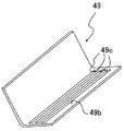
また、図8、図9に示すように、押さえ部材49の押さえ部49bに開口部49cを設けてもよい。かかる構成とすることで、押さえ部材49の熱容量をより一層少なくすることができ、定着ベルト43を必要な温度に昇温させるまでの待機時間を短くすることができ、かつ、省エネルギー化を図ることができる。
Further, as shown in FIGS. 8 and 9, an
また、押さえ部材49の押さえ部49bの先端を、なるべく定着ローラ41に近づけて配置するのが好ましい。これは、図5に示すように、押さえ部材49の押さえ部49bにより加圧ローラ45に押して当てられたポストニップ部N2と、定着ニップN1との間に、内側から部材により加圧ローラに押圧されていない境界領域N2sが生じる。この境界領域N2sにおける加圧ローラ45への当接圧は、ポストニップ部N2の当接圧よりも低い。このように、記録シート搬送方向上流側の当接圧が、下流側よりも低い箇所があると、次のような問題が生じる。すなわち、上記境界領域N2sは、定着ニップN1よりも圧力が低いため、上述したように、記録シートから水蒸気が放出され、記録シートと定着ベルトとの間などに気泡が発生する。また、トナー像の中の空気も熱膨張により漏れ出し記録シートと定着ベルトとの間に気泡が発生する。そして、この境界領域N2sよりも圧が高いポストニップ部N2に記録シートが突入すると、この気泡が押さえ部材49の押さえ力により押し出されるような形となり、記録シートPの表面を移動する。記録シート上のトナー像は定着ニップN1を出た直後であり、完全に固化しておらず、記録シートの表面の気泡の移動によりトナー像が乱され、光沢ムラなどの異常画像が生じる。
In addition, it is preferable to arrange the tip of the
よって、押さえ部材49で定着ニップN1近傍まで定着ベルト43を押さえ、上記境界領域N2sを狭くするのが好ましい。上記境界領域N2sを狭くすることで、上記境界領域で気泡が発生するのを抑制することができる。このため、本実施形態においては、押さえ部材49を、支持板24に固定された固定端から加圧ローラ側へ延び、途中で定着ニップN1側に屈曲する構成とし、押さえ部材49の記録シート搬送方向上流側端部を、自由端とした。これにより、上記定着ニップ側と反対側に屈曲させて、記録シート搬送方向下流側端部を、自由端とした場合に比べて、押さえ部材49を、定着ニップN1の近傍に配置することができ、上記境界領域N2sを狭くすることができる。
Therefore, it is preferable that the fixing
また、同様な理由で、押さえ部材49の定着ベルトへの押圧力も、均一もしくは記録シート搬送方向下流にいくに従い減少させるなどして、下流側の押圧力が、上流側の押圧力よりも高くならないようにするのが好ましい。これにより、ポストニップ部N2において、放出された水蒸気の気泡が押し出されて、記録シートの表面を移動するのを防止することができる。これにより、ポストニップ部N2で光沢ムラなどの異常画像が生じるのを抑制することができる。
For the same reason, the pressing force of the pressing
下記表2は、上記境界領域N2sの幅についての評価試験の結果を示すものである。 Table 2 below shows the results of an evaluation test for the width of the boundary region N2s.
表2における評価試験は、定着ニップN1の面圧を40[N/cm2]、ポストニップ部N2の面圧を2.84[N/cm2](0.29[kg/cm2])にし、A3用紙にベタ画像を作成し、その作成した画像を、目視で、光沢ムラを評価した。各面圧は、ISCANを用いて測定した。光沢ムラが確認できない場合を、「OKレベル」とし、光沢ムラが確認できた場合を、「NGレベル(レベル悪い)」とした。また、境界領域N2Sの面圧は、定着ニップ出口から押さえ部材の上流側端部までの平均面圧であり、ポストニップ部N2の面圧は、押さえ部材の定着ベルト移動方向上流側端部から下流側端部までの平均面圧である。ポストニップ部N2の面圧は、定着ベルト移動方向上流側から下流側へ向かって単調減少させており、ポストニップ部N2の上流側端部の面圧は、凡そ8[N/cm2]である。 In the evaluation test in Table 2, the surface pressure of the fixing nip N1 is 40 [N / cm 2 ], and the surface pressure of the post nip N2 is 2.84 [N / cm 2 ] (0.29 [kg / cm 2 ]). A solid image was created on A3 paper, and the created image was visually evaluated for uneven gloss. Each surface pressure was measured using ISCAN. The case where gloss unevenness could not be confirmed was designated as “OK level”, and the case where gloss unevenness was confirmed was designated as “NG level (bad level)”. The surface pressure of the boundary region N2S is an average surface pressure from the fixing nip outlet to the upstream end of the pressing member, and the surface pressure of the post nip N2 is downstream from the upstream end of the pressing member in the fixing belt moving direction. Average surface pressure to the side edge. The surface pressure of the post nip portion N2 is monotonously decreased from the upstream side toward the downstream side in the fixing belt moving direction, and the surface pressure at the upstream end portion of the post nip portion N2 is about 8 [N / cm 2 ].
表2からわかるように、境界領域N2sの幅を2.8mm以下とすることで、境界領域N2sで気泡が発生するのを抑制することができ、ポストニップ部N2で押し出されて記録シートの表面を移動するのを抑制することができる。その結果、光沢ムラが発生せず、光沢ムラを「OKレベル」にすることができたと考えられる。 As can be seen from Table 2, by setting the width of the boundary region N2s to 2.8 mm or less, it is possible to suppress the generation of bubbles in the boundary region N2s, and the surface of the recording sheet is pushed out by the post nip portion N2. It can suppress moving. As a result, it is considered that gloss unevenness did not occur and the gloss unevenness could be set to “OK level”.
また、図5に示すように、定着ニップN1の出口における加圧ローラ45の接線X1と、定着ローラ41の接線X2とのなす角度θは、45°以上とするのが好ましい。本出願人は、上記角度θが13°のときと、45°のときとで評価試験を行ったところ、上記θが13°のときは、光沢ムラが発生しており、上記角度θが45°のときは、光沢ムラが発生していなかった。これは、上記角度θが13°のときは、定着ニップN1出口付近における記録シートPと定着ローラ41との距離が近い。そのため、定着ニップN1を出た記録シートP1は、定着ローラ41の熱の影響を受ける。その結果、境界領域N2sでの水蒸気の放出や、トナー像中の空気の熱膨張が大きくなり、境界領域N2sで発生した気泡が大きくなりやすい。その結果、境界領域N2sの面圧と、ポストニップ部N2の面圧との差が小さくても、気泡の体積が大きいため、ポストニップ部N2で潰されたときの気泡の広がりが大きくなり、上記光沢ムラが発生したと考えられる。一方、上記角度θを45°以上とすることで、境界領域N2sにおいて記録シートPが受ける定着ローラ41の熱の影響を低減することができる。これにより、境界領域N2sにおいて、記録シートPからの水蒸気の放出やトナー中の空気の熱膨張を抑えることができ、気泡が大きくなるのを抑制することができる。その結果、ポストニップ部で気泡が押しつぶされたときのその気泡の広がりが抑えられ、光沢ムラが確認できないレベルにできたと考えられる。
As shown in FIG. 5, it is preferable that the angle θ formed between the tangent line X1 of the
また、押さえ部材49により常に定着ベルト43を加圧部材45に当接させていると、押さえ部材49の押さえ力が、常に加圧ローラ45や定着ベルト43にかかり続け、加圧ローラ45や定着ベルト43の寿命低下を招くおそれがある。また、ウォームアップ時などの通紙時以外の回動駆動時において、押さえ部材49により定着ベルト43を加圧ローラ45に当接させていると、定着ベルト内周面と押さえ部材49との摩擦により定着ベルト43が早期に摩耗してしまう。そのため、非通紙時や、水蒸気の放出や吸収で波打ちが生じ難い厚紙やOHPなどの記録シート搬送時は、押さえ部材49の当接を解除するのが好ましい。また、厚紙においては、厚紙の先端が押さえ部材49の自由端にぶつかり、押さえ部材49が記録シート搬送方向下流側に撓んだり、定着ベルト43が厚紙の先端と押さえ部材49の自由端とに挟まれ、定着ベルト43が傷ついたりするおそれがある。従って、記録シートが厚紙のときは、押さえ部材を解除位置に位置させるのが好ましい。
Further, if the fixing
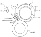
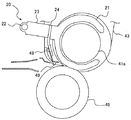
図10は、押さえ部材49を、定着ベルト43を加圧ローラ45に当接する当接位置と、当接を解除する解除位置との間を移動させる移動機構について説明する斜視図である。
図10に示すように、移動機構20は、押さえ部材49が固定されて支持する屈曲した支持板24を備えている。押さえ部材49のこの支持板24の下端部にネジ止めされている。この支持板24の定着ローラの軸方向両端には、アーム部材23と、ガイド部材21とが設けられている。このアーム部材23の先端には、カムなどで構成される駆動手段に接続される接続部材22が固定されている。この接続部材22は、定着装置筐体側面に設けられた定着ローラの回転中心を中心した円弧状の長穴に保持されている。
FIG. 10 is a perspective view illustrating a moving mechanism that moves the pressing
As shown in FIG. 10, the moving
図11は、押さえ部材49を、定着ベルト43を加圧ローラに当接させる当接位置に位置させた状態を示す図であり、図12は、押さえ部材49を、定着ベルト43の加圧ローラ45へ当接を解除した解除位置に位置させた状態を示す図である。
図11、図12に示すように、ガイド部材21は、定着ローラ41の芯金部41aに取り付けられている。定着ニップN1へ搬送される記録シートPが、波打ちが生じ難い記録シートのときは、押さえ部材49を解除位置に位置させる。波打ちが生じ難い記録シートとしては、厚紙などのコシの強い記録シートやOHPなど水分を含まない記録シートが挙げられる。厚紙などのコシの強い記録シートにおいては、水蒸気の放出で乾燥したり水蒸気を吸収したりしても自らのコシにより波打ちが生じ難いのである。OHPなど水分を含まない記録シートは、そもそも水蒸気の放出や吸収が発生しないため、波打ちが生じない。
FIG. 11 is a diagram illustrating a state in which the pressing
As shown in FIGS. 11 and 12, the
押さえ部材49を解除位置に位置させるときは、駆動手段により、接続部材22を、図中上方に押し込む。すると、移動機構20が、ガイド部材21によりガイドされながら、定着ローラの中心にして、図中矢印A方向に回動する。すると、図12に示すように、押さえ部材49が、加圧ローラ45に対して離間する方向へ移動し、押さえ部材が定着ベルトから離間して、加圧ローラとの当接が解除される。
When the pressing
このように、定着ニップN1に搬送される記録シートが、厚紙やOHPなどの波打ちが生じ難い記録シートのときは、押さえ部材49を解除位置に位置させることにより、加圧ローラ45や定着ベルト43の負荷を低減することができ、加圧ローラ45や定着ベルト43の寿命を延ばすことができる。また、定着ベルト43と押さえ部材49との摩擦を低減することができる。特に、本実施形態では、押さえ部材49が解除位置に位置するとき、定着ベルト43の内周面から離間している。そのため、解除位置に位置しているとき、定着ベルト43の内周面との押さえ部材49との摩擦が生じることがなく、定着ベルト43の摩耗をより一層抑制することができる。
As described above, when the recording sheet conveyed to the fixing nip N1 is a recording sheet such as thick paper or OHP that is unlikely to be undulated, the pressing
特に、厚紙のときに押さえ部材49を解除位置に位置させることで、押さえ部材49の自由端が厚紙の搬送方向先端とぶつかることがなくなり、定着ベルト43や押さえ部材49の寿命を延ばすことができる。
In particular, by positioning the pressing
また、定着装置に記録シートが通紙されていない非通紙時においても、押さえ部材49を解除位置に位置させることで、加圧ローラ45や定着ベルト43の摩耗を抑制することができ、加圧ローラ45や定着ベルト43の寿命を延ばすことができる。具体的には、待機時には、押さえ部材49を解除位置に位置させ例えば、記録シートが二次転写ニップを通過したタイミングで解除位置から当接位置へ押さえ部材を移動させ、記録シートが定着装置に進入する前に押さえ部材を当接位置に位置させる。そして、記録シートが定着装置から排出されたら、押さえ部材49を解除位置へ移動させ、定着ベルトから離間させる。これにより、定着ベルトや加圧ローラの押さえ部材の押さえによる負荷を低減することができる。
Further, even when the recording sheet is not passed through the fixing device, the pressing
上述では、電子写真方式を用いた複写機、プリンタ等の画像形成装置に、本発明の定着装置を適用した実施形態について説明したが、例えば、インクジェット方式を用いた複写機、プリンタ等の画像形成装置の記録紙(用紙)上に担持された未乾燥インク像を乾燥する定着装置にも本発明の定着装置を適用することができる。 In the above description, an embodiment in which the fixing device of the present invention is applied to an image forming apparatus such as a copying machine or a printer using an electrophotographic system has been described. For example, image forming such as a copying machine or a printer using an ink jet system is used. The fixing device of the present invention can also be applied to a fixing device that dries an undried ink image carried on a recording paper (paper) of the apparatus.
以上に説明したものは一例であり、以下の態様毎に特有の効果を奏する。
(態様1)
複数の張架部材に張架される無端状の定着ベルト43と、前記複数の張架部材のうちのひとつである定着ローラ41などのニップ形成部材と、前記ニップ形成部材に対向して前記定着ベルトを介してニップを形成する加圧ローラ45などの加圧部材と、前記定着ベルトを加熱する熱源44と、前記ニップ形成部材よりも前記定着ベルト移動方向下流側で、前記定着ベルト43を介して前記加圧部材と接触しない位置に配置され、前記定着ベルト43の内周面に当接して、前記定着ベルト43の曲率を大きくする分離補助部材48などの分離部材とを備えた定着装置において、前記ニップ出口から前記分離部材の前記定着ベルト移動方向上流側端部までの間に、前記定着ベルトの内周面に当接して前記定着ベルトを押さえる押さえ部材を設けた。
上記特許文献1において、定着ニップ通過後の記録媒体のスジ状のしわは、定着ニップ通過後の記録媒体に波打ちが生じ、その波打ちが生じた記録媒体が、排紙ローラ対に搬送されるときに生じる。そして、この定着ニップ通過後の記録媒体に波打ちは、定着ニップN1などのニップを出た記録媒体が分離部材の分離位置へ移動するまでの間に発生する。これは、以下の理由で発生する。すなわち、上述した特許文献1に記載の定着装置においては、ニップにおいて記録媒体のトナー像が形成された面が定着ベルトに圧接されながら加熱されることでトナーが溶融して記録媒体にトナー像が定着される。ニップを出た記録媒体はニップで溶融したトナーが定着ベルトに付着した状態で、分離部材の分離位置へ搬送され、この分離位置で定着ベルトから分離される。定着ニップにおいて、記録媒体が加熱されることで、記録媒体に含まれる水分が気化して水蒸気となるが、ニップにおいては、高いニップ圧で記録媒体を押さえ付けているため、記録媒体から水蒸気が放出されにくい。しかし、ニップから分離位置までの記録媒体上のトナー像が定着ベルトに付着した状態で搬送される間は、記録媒体には圧がかかっていないため、この間でニップで発生した水蒸気の放出が起こりやすい。水蒸気は、記録媒体の定着ベルト側の面と反対側の面から主に放出される。また、トナー像が形成された画像部よりも高さが低く、定着ベルトと非画像部との間には隙間が生じており、この隙間にも水蒸気が放出される。水蒸気が放出されることにより、記録媒体の繊維が乾燥して縮み波打ちが発生する。
また、定着ベルトと非画像部との隙間に放出された水蒸気は、その隙間に留まり再び記録媒体に吸収される。自ら放出した水蒸気が再吸収されることで、記録媒体を濡らし繊維が延びて記録媒体に波打ちが生じてしまう。
このように、ニップを出た記録媒体が上記分離位置へ移動するまでの間に、水蒸気の放出による乾燥や、水蒸気の再吸収による濡れにより記録媒体の繊維に伸縮が発生し、この間で記録媒体に波打ちが生じるのである。
これに対し(態様1)においては、上記ニップから出た記録媒体が、定着ベルトと加圧部材とに挟まれた状態、若しくは、加圧部材と隙間がほとんどない状態で搬送されるように定着ベルトを押し付け部材で押さえることで、以下の利点を有する。すなわち、記録媒体が分離位置まで移動する間で、記録媒体からの水蒸気の放出による乾燥で記録媒体が波打とうとすると、上記定着ベルトや加圧部材に当たり、その波打ちが阻害される。その結果、上記ニップから分離部材までの間での水蒸気の放出による記録媒体の波打ちが抑制される。
また、ニップから分離部材までの間で、放出した水蒸気を再吸収して記録媒体が波打とうとする場合も、上記定着ベルトや加圧部材によりその波打ちが阻害される。その結果、ニップから分離部材までの間で、水蒸気の再吸収による記録媒体の波打ちも抑制される。
このように、ニップ通過後の記録媒体の波打ちが抑制されることで、波打ちが生じた記録媒体が、排紙ローラ対により搬送されるのを抑制することができ、定着ニップ通過後の記録媒体にスジ状のしわが生じるのを抑制することができる。
What was demonstrated above is an example, and there exists an effect peculiar for every following aspect.
(Aspect 1)
An endless fixing
In
Further, the water vapor released into the gap between the fixing belt and the non-image portion remains in the gap and is again absorbed by the recording medium. The water vapor released by itself is reabsorbed, so that the recording medium is wetted and the fibers are extended, and the recording medium is wavy.
Thus, until the recording medium exiting the nip moves to the separation position, the fibers of the recording medium expand and contract due to drying due to the release of water vapor and wetting due to the reabsorption of water vapor. The undulations occur.
On the other hand, in (Aspect 1), the recording medium exiting from the nip is fixed so as to be conveyed in a state of being sandwiched between the fixing belt and the pressure member, or having almost no gap between the pressure member and the pressure member. By pressing the belt with the pressing member, the following advantages are obtained. That is, while the recording medium moves to the separation position, if the recording medium undulates by drying due to the release of water vapor from the recording medium, the recording medium hits the fixing belt or the pressure member and the undulation is inhibited. As a result, the undulation of the recording medium due to the release of water vapor between the nip and the separating member is suppressed.
Further, even when the released water vapor is reabsorbed between the nip and the separating member to cause the recording medium to undulate, the waving is inhibited by the fixing belt and the pressure member. As a result, the undulation of the recording medium due to the reabsorption of water vapor is also suppressed between the nip and the separating member.
In this way, by suppressing the undulation of the recording medium after passing through the nip, the recording medium in which the undulation has occurred can be suppressed from being conveyed by the discharge roller pair, and the recording medium after passing through the fixing nip. It is possible to suppress the generation of streak-like wrinkles.
(態様2)
態様1において、前記押さえ部材は、前記定着ベルトを前記加圧部材に当接させる。
これによれば、上記ニップから出た記録媒体は、定着ベルトと加圧部材とに挟まれた状態で、分離位置へ搬送される。これにより、記録媒体からの水蒸気の放出が起こったとしても、記録媒体が押さえ部材により定着ベルトを介して加圧部材に押さえられた状態で水蒸気が放出されることになる。これにより、水蒸気の放出により記録媒体の繊維が縮もうとするが、上記押さえ部材の押さえ力で記録媒体全面を加圧部材に押さえているので、繊維が縮むことができない。その結果、上記ニップから分離部材までの間での水蒸気の放出による記録媒体の波打ちが抑制される。
また、ニップから分離部材までの間で、放出した水蒸気の再吸収が発生しても、記録媒体が押さえ部材により定着ベルトを介して加圧部材に押さえられた状態で水蒸気の再吸収が行われる。これにより、水蒸気の吸収で記録媒体の繊維が伸びようとしても、上記押さえ部材の押さえ力で記録媒体全面を加圧部材に押さているので、繊維が伸びることができない。その結果、ニップから分離部材までの間で、水蒸気の再吸収による記録媒体の波打ちも抑制される。
(Aspect 2)
In the first aspect, the pressing member causes the fixing belt to contact the pressure member.
According to this, the recording medium that has come out of the nip is conveyed to the separation position while being sandwiched between the fixing belt and the pressure member. As a result, even if water vapor is released from the recording medium, the water vapor is released in a state where the recording medium is pressed by the pressing member via the fixing belt by the pressing member. Thereby, the fibers of the recording medium try to shrink due to the release of water vapor, but the fibers cannot be shrunk because the entire surface of the recording medium is pressed against the pressing member by the pressing force of the pressing member. As a result, the undulation of the recording medium due to the release of water vapor between the nip and the separating member is suppressed.
Further, even if reabsorption of the released water vapor occurs between the nip and the separating member, the water vapor is reabsorbed while the recording medium is pressed by the pressure member via the fixing belt by the pressing member. . As a result, even if the fibers of the recording medium are about to expand due to the absorption of water vapor, the fibers cannot be extended because the entire surface of the recording medium is pressed against the pressure member by the pressing force of the pressing member. As a result, the undulation of the recording medium due to the reabsorption of water vapor is also suppressed between the nip and the separating member.
(態様3)
態様1または2において、先端が前記定着ベルト43の外周面と非接触で、分離補助部材48などの分離部材と対向する分離板46などの第二分離部材を備え、前記分離部材を、前記押さえ部材49よりも剛性を高くした。
これによれば、実施形態で説明したように、分離補助部材48などの分離部材の変形を抑制することができ、分離板46などの第二分離部材と定着ベルト43の微小隙間が変動するのを抑制することができる。これにより、定着ベルト43が、第二分離部材の先端に当接して、定着ベルト43の外周面が傷つくのを抑制することができる。また、定着ベルトに付着した記録シートなどの記録媒体の搬送方向先端が、第二分離部材に当接せず、分離不良が生じるのを抑制することができる。
(Aspect 3)
In the
According to this, as described in the embodiment, deformation of the separation member such as the
(態様4)
態様1乃至3いずれかにおいて、分離補助部材48などの分離部材の前記定着ベルト43との接触面を円弧状とした。
これによれば、実施形態で説明したように、定着ベルト43を、この円弧状の接触面に倣ってスムーズに移動させることができる。
(Aspect 4)
In any one of the first to third aspects, the contact surface of the separation member such as the
According to this, as described in the embodiment, the fixing
(態様5)
態様1乃至4いずれかにおいて、前記押さえ部材を、前記定着ベルトを介して前記加圧部材に接触させる構成であって、前記押さえ部材49を、バネ弾性を有する板状部材とした。
これによれば、実施形態で説明したように、押さえ部材をブロック部材で構成した場合に比べて、押さえ部材の熱容量を低減することができる。これにより、押さえ部材49による温度損失を抑制できる。その結果、押さえ部材49をブロック状の部材とした場合に比べて、定着ベルト43を必要な温度に昇温させるまでの待機時間を短くすることができる。また、押さえ部材49をブロック状の部材とした場合に比べて、消費電力の増加を抑制することができ、省エネルギー化を図ることができる。
また、押さえ部材49が、バネ弾性を有することで、加圧ローラ45などの加圧部材に良好に追随することができ、定着ベルト43を良好に加圧部材に当接させることができる。
(Aspect 5)
In any one of the first to fourth aspects, the pressing member is configured to contact the pressing member via the fixing belt, and the pressing
According to this, as described in the embodiment, the heat capacity of the pressing member can be reduced as compared with the case where the pressing member is configured by a block member. Thereby, the temperature loss by the pressing
Further, since the pressing
(態様6)
また、態様5において、前記定着ベルト43の内周面に当接して、前記定着ベルト43を加圧ローラ45などの加圧部材に押し当てる押さえ部49bと、該押さえ部49bよりも記録シートPなどの記録媒体の移動方向下流側で、前記加圧部材から離間する方向に屈曲した剥離部49aとを備える。
これによれば、押さえ部49bにより、良好に記録媒体を、加圧ローラ45などの加圧部材に押し当てることができる。また、押さえ部49bと加圧部材とに挟まれた定着ベルト43は、この屈曲した剥離部49aに沿って移動し、その移動方向が急激に変化する。これにより、剥離部49aにおいて、記録媒体を曲率分離させることができる。その結果、この剥離部49aにおける曲率、分離補助部材などの分離部材における曲率と、複数個所で、記録媒体の分離を行うことができ、記録媒体を、定着ベルト43から良好に分離させることができる。
(Aspect 6)
Further, in the aspect 5, the
According to this, the recording medium can be favorably pressed against the pressure member such as the
(態様7)
また、態様5または6において、前記押さえ部材49は、前記定着ベルト43の内周面に当接して、前記定着ベルト43を加圧ローラ45などの加圧部材に当接させる押さえ部49bを有し、前記押さえ部49bを、前記加圧部材の表面形状に倣う形状とした。
これにより、実施形態で説明したように、押さえ部材49で均一に定着ベルト43を加圧部材に当接させることができる。その結果、ポストニップ部N2などの押さえ部材49の押さえ範囲において、記録媒体と定着ベルトなどの間にある気泡が押し出されて、記録媒体の表面を移動するのを防止することができる。これにより、ポストニップ部N2で光沢ムラなどの異常画像が生じるのを抑制することができる。
(Aspect 7)
In the aspect 5 or 6, the pressing
As a result, as described in the embodiment, the fixing
(態様8)
態様5乃至7いずれかにおいて、押さえ部材49の定着ベルト移動方向上流側端部を自由端とした。
これによれば、実施形態で説明したように、押さえ部材49を、定着ニップN1に近接させることができ、定着ニップN1と、ポストニップ部N2などの押さえ部材49の押さえ範囲との間の境界領域N2sの幅を狭くすることができ、光沢ムラが発生するのを抑制することができる。
(Aspect 8)
In any one of modes 5 to 7, the upstream end of the pressing
According to this, as described in the embodiment, the pressing
(態様9)
態様1乃至8いずれかにおいて、定着ニップN1などニップの出口から前記押さえ部材49の前記定着ベルト移動方向上流側端部までの距離を2.8mm以下とした。
これによれば、実施形態で説明したように、定着ニップN1などのニップと、ポストニップ部N2などの押さえ部材49の押さえ範囲との間の境界領域の面圧の低下を抑制することができ、光沢ムラの発生を抑制することができる。
(Aspect 9)
In any one of
According to this, as described in the embodiment, it is possible to suppress a decrease in the surface pressure in the boundary region between the nip such as the fixing nip N1 and the pressing range of the pressing
(態様10)
態様1乃至9いずれかにおいて、前記押さえ部材49の定着ベルト移動方向下流側の押圧力を、上流側の押圧力以下とした。
これによれば、実施形態で説明したように、ポストニップ部N2などの押さえ部材49の押さえ範囲で、光沢ムラが発生するのを抑制することができる。
(Aspect 10)
In any one of the first to ninth aspects, the pressing force on the downstream side of the pressing
According to this, as described in the embodiment, it is possible to suppress the occurrence of uneven gloss in the pressing range of the pressing
(態様11)
感光体3などの潜像担持体と、潜像担持体上にトナー像を形成するトナー像形成手段(帯電装置5、光書込ユニット1、現像装置4などで構成)と、前記トナー像を前記潜像担持体上から記録媒体上に転写する転写手段(一次転写ユニットおよび二次転写ユニットで構成)と、前記記録材上に転写されたトナー像を該記録材に定着させる定着手段と、を備えた画像形成装置において、前記定着手段として、態様1乃至10いずれかに記載の定着装置を用いる。
これによれば、定着ベルトのばたつきや出力された記録媒体に波打ちが生じるのを抑制することができる。
(Aspect 11)
A latent image carrier such as a photoreceptor 3, toner image forming means (comprising charging device 5,
According to this, it is possible to suppress the flapping of the fixing belt and the occurrence of undulations in the output recording medium.
1:光書込ユニット
2:作像ユニット
3:感光体
4:現像装置
5:帯電装置
10:研磨装置
20:接離機構
21:ガイド部材
22:接続部材
23:アーム部材
24:支持板
40:定着装置
41:定着ローラ
41a:芯金部
42:加熱ローラ
43:定着ベルト
44:熱源
45:加圧ローラ
46:分離板
47:テンションローラ
48:分離補助部材
49:押さえ部材
49a:剥離部
49b:押さえ部
60:一次転写ユニット
78:二次転写ユニット
N1:定着ニップ
N2:ポストニップ部
N2s:境界領域
P:記録シート
1: Optical writing unit 2: Image forming unit 3: Photoconductor 4: Developing device 5: Charging device 10: Polishing device 20: Contact / separation mechanism 21: Guide member 22: Connection member 23: Arm member 24: Support plate 40: Fixing device 41: Fixing
Claims (11)
前記複数の張架部材のうちのひとつであるニップ形成部材と、
前記ニップ形成部材に対向して前記定着ベルトを介してニップを形成する加圧部材と、
前記定着ベルトを加熱する熱源と、
前記ニップ形成部材よりも前記定着ベルトの移動方向下流側で、前記定着ベルトを介して前記加圧部材から離間した位置に配置され、前記定着ベルトを張架する分離部材とを備えた定着装置において、
前記ニップの出口から前記分離部材の前記定着ベルト移動方向上流側端部までの間に、前記定着ベルトの内周面に当接して前記定着ベルトを押さえる押さえ部材を設けたことを特徴とする定着装置。 An endless fixing belt stretched over a plurality of stretch members;
A nip forming member that is one of the plurality of stretching members;
A pressure member that forms a nip through the fixing belt opposite the nip forming member;
A heat source for heating the fixing belt;
A fixing device including a separating member that is disposed downstream of the nip forming member in the moving direction of the fixing belt and spaced from the pressure member via the fixing belt, and stretches the fixing belt; ,
A fixing member is provided between the outlet of the nip and the upstream end of the separation member in the fixing belt moving direction so as to contact the inner peripheral surface of the fixing belt and press the fixing belt. apparatus.
前記押さえ部材は、前記定着ベルトを前記加圧部材に当接させることを特徴とする定着装置。 The fixing device according to claim 1,
The fixing device, wherein the pressing member causes the fixing belt to contact the pressure member.
先端が前記定着ベルトの外周面と非接触で、分離部材と対向する第二分離部材を備え、
前記分離部材を、前記押さえ部材よりも剛性を高くしたことを特徴とする定着装置。 The fixing device according to claim 1 or 2,
A leading end is not in contact with the outer peripheral surface of the fixing belt, and includes a second separating member facing the separating member;
A fixing device characterized in that the separating member has higher rigidity than the pressing member.
前記分離部材の前記定着ベルトとの接触面を円弧状としたことを特徴とする定着装置。 The fixing device according to any one of claims 1 to 3,
The fixing device according to claim 1, wherein a contact surface of the separation member with the fixing belt has an arc shape.
前記押さえ部材は、前記定着ベルトを前記加圧部材に当接させるものであって、
前記押さえ部材を、バネ弾性を有する板状部材としたことを特徴とする定着装置。 The fixing device according to claim 1,
The pressing member is for bringing the fixing belt into contact with the pressure member,
A fixing device, wherein the pressing member is a plate-like member having spring elasticity.
前記押さえ部材は、前記定着ベルトの内周面に当接して、前記定着ベルトを前記加圧部材に当接させる押さえ部と、該押さえ部よりも前記定着ベルト移動方向下流側で、前記加圧部材から離間する方向に屈曲した剥離部とを備えることを特徴とする定着装置。 The fixing device according to claim 5.
The pressing member is in contact with an inner peripheral surface of the fixing belt and presses the pressing belt against the pressing member, and the pressing member is located on the downstream side of the pressing belt in the fixing belt moving direction. A fixing device comprising: a peeling portion bent in a direction away from the member.
前記押さえ部材は、前記定着ベルトの内周面に当接して、前記定着ベルトを前記加圧部材に当接させる押さえ部を有し、
前記押さえ部を、前記加圧部材の表面形状に倣う形状としたことを特徴とする定着装置。 In the fixing device according to claim 5 or 6,
The pressing member has a pressing portion that contacts the inner peripheral surface of the fixing belt and causes the fixing belt to contact the pressure member,
The fixing device, wherein the pressing portion has a shape that follows the surface shape of the pressure member.
前記押さえ部材の前記定着ベルト移動方向上流側端部を自由端としたことを特徴とする定着装置。 The fixing device according to any one of claims 5 to 7,
A fixing device characterized in that the upstream end of the pressing member in the fixing belt moving direction is a free end.
前記ニップの出口から前記押さえ部材の前記定着ベルト移動方向上流側端部までの距離を2.8mm以下としたことを特徴とする定着装置。 The fixing device according to claim 1,
The fixing device is characterized in that the distance from the exit of the nip to the upstream end of the pressing member in the moving direction of the fixing belt is 2.8 mm or less.
前記押さえ部材の前記定着ベルト移動方向下流側の押圧力を、上流側の押圧力以下としたことを特徴とする定着装置。 The fixing device according to any one of claims 1 to 9,
The fixing device according to claim 1, wherein the pressing force of the pressing member on the downstream side in the fixing belt moving direction is equal to or lower than the pressing force on the upstream side.
潜像担持体上にトナー像を形成するトナー像形成手段と、
前記トナー像を前記潜像担持体上から記録媒体上に転写する転写手段と、
前記記録材上に転写されたトナー像を該記録媒体に定着させる定着手段と、を備えた画像形成装置において、
前記定着手段として、請求項1乃至10いずれかに記載の定着装置を用いることを特徴とする画像形成装置 A latent image carrier;
Toner image forming means for forming a toner image on the latent image carrier;
Transfer means for transferring the toner image from the latent image carrier onto a recording medium;
A fixing unit that fixes the toner image transferred onto the recording material to the recording medium;
An image forming apparatus using the fixing device according to claim 1 as the fixing unit.
Priority Applications (3)
| Application Number | Priority Date | Filing Date | Title |
|---|---|---|---|
| JP2016055951A JP6701563B2 (en) | 2016-03-18 | 2016-03-18 | Fixing device and image forming device |
| EP17154230.1A EP3220202A1 (en) | 2016-03-18 | 2017-02-01 | Fixing device and image forming apparatus |
| US15/444,946 US10088786B2 (en) | 2016-03-18 | 2017-02-28 | Fixing device and image forming apparatus |
Applications Claiming Priority (1)
| Application Number | Priority Date | Filing Date | Title |
|---|---|---|---|
| JP2016055951A JP6701563B2 (en) | 2016-03-18 | 2016-03-18 | Fixing device and image forming device |
Publications (2)
| Publication Number | Publication Date |
|---|---|
| JP2017173364A true JP2017173364A (en) | 2017-09-28 |
| JP6701563B2 JP6701563B2 (en) | 2020-05-27 |
Family
ID=57956202
Family Applications (1)
| Application Number | Title | Priority Date | Filing Date |
|---|---|---|---|
| JP2016055951A Expired - Fee Related JP6701563B2 (en) | 2016-03-18 | 2016-03-18 | Fixing device and image forming device |
Country Status (3)
| Country | Link |
|---|---|
| US (1) | US10088786B2 (en) |
| EP (1) | EP3220202A1 (en) |
| JP (1) | JP6701563B2 (en) |
Cited By (1)
| Publication number | Priority date | Publication date | Assignee | Title |
|---|---|---|---|---|
| JP2019191247A (en) * | 2018-04-19 | 2019-10-31 | コニカミノルタ株式会社 | Fixation device and image formation apparatus |
Families Citing this family (9)
| Publication number | Priority date | Publication date | Assignee | Title |
|---|---|---|---|---|
| US10012937B2 (en) * | 2016-03-18 | 2018-07-03 | Ricoh Company, Ltd. | Fixing device and image forming apparatus including a fixing belt, a presser, and a gap retainer |
| JP6979164B2 (en) | 2017-03-17 | 2021-12-08 | 株式会社リコー | Fixing device, image forming device |
| US10488796B2 (en) | 2017-07-05 | 2019-11-26 | Ricoh Company, Ltd. | Fixing device controller, image forming apparatus, fixing device control method, and non-transitory computer-readable recording medium storing fixing device control program |
| JP7057886B2 (en) | 2017-07-11 | 2022-04-21 | 株式会社リコー | Sheet transfer device, fixing device and image forming device |
| JP6926755B2 (en) | 2017-07-13 | 2021-08-25 | 株式会社リコー | Fixing device and image forming device |
| JP7275626B2 (en) | 2018-03-02 | 2023-05-18 | 株式会社リコー | Image forming apparatus and image forming method |
| JP7271972B2 (en) * | 2019-02-01 | 2023-05-12 | 株式会社リコー | HEATER MEMBER FIXING HOLDER, HEATER MEMBER FIXING AND HOLDING METHOD, FIXING DEVICE, AND IMAGE FORMING APPARATUS |
| US11150583B2 (en) | 2019-09-27 | 2021-10-19 | Ricoh Company, Ltd. | Belt device and image forming apparatus incorporating same |
| JP2023057346A (en) | 2021-10-11 | 2023-04-21 | 株式会社リコー | Heating device and liquid discharge device |
Citations (4)
| Publication number | Priority date | Publication date | Assignee | Title |
|---|---|---|---|---|
| JP2006243471A (en) * | 2005-03-04 | 2006-09-14 | Fuji Xerox Co Ltd | Fixing device and image forming apparatus |
| JP2007065092A (en) * | 2005-08-29 | 2007-03-15 | Fuji Xerox Co Ltd | Fixing apparatus and image forming apparatus |
| JP2013156668A (en) * | 2013-05-23 | 2013-08-15 | Ricoh Co Ltd | Fixing device and image forming apparatus |
| US8897684B2 (en) * | 2012-06-13 | 2014-11-25 | Xerox Corporation | Apparatus, method and system for controlling strip radius in a fuser unit useful in printing |
Family Cites Families (50)
| Publication number | Priority date | Publication date | Assignee | Title |
|---|---|---|---|---|
| JP4748885B2 (en) | 2001-06-21 | 2011-08-17 | 株式会社リコー | Belt fixing device and image forming apparatus |
| JP4655822B2 (en) | 2005-08-23 | 2011-03-23 | 富士ゼロックス株式会社 | Fixing apparatus and image forming apparatus |
| JP4609240B2 (en) | 2005-08-29 | 2011-01-12 | 富士ゼロックス株式会社 | Fixing apparatus and image forming apparatus |
| JP2007072275A (en) | 2005-09-08 | 2007-03-22 | Fuji Xerox Co Ltd | Fixing apparatus and image forming apparatus |
| JP2007114415A (en) | 2005-10-19 | 2007-05-10 | Fuji Xerox Co Ltd | Fixing apparatus and image forming apparatus |
| JP4857708B2 (en) | 2005-10-24 | 2012-01-18 | 富士ゼロックス株式会社 | Fixing apparatus and image forming apparatus |
| JP4696846B2 (en) | 2005-10-25 | 2011-06-08 | 富士ゼロックス株式会社 | Fixing device |
| JP2007121451A (en) | 2005-10-25 | 2007-05-17 | Fuji Xerox Co Ltd | Fixing device and image forming apparatus |
| JP4923554B2 (en) | 2005-12-16 | 2012-04-25 | 富士ゼロックス株式会社 | Fixing apparatus and image forming apparatus |
| JP4792968B2 (en) | 2005-12-27 | 2011-10-12 | 富士ゼロックス株式会社 | Fixing apparatus and image forming apparatus |
| JP2007310054A (en) | 2006-05-17 | 2007-11-29 | Ricoh Co Ltd | Belt fixing device and image forming apparatus |
| JP2008102484A (en) * | 2006-09-19 | 2008-05-01 | Konica Minolta Business Technologies Inc | Fixing device |
| JP5045069B2 (en) | 2006-11-15 | 2012-10-10 | 富士ゼロックス株式会社 | Fixing device |
| JP2008134356A (en) | 2006-11-27 | 2008-06-12 | Fuji Xerox Co Ltd | Fixing device and image forming device |
| JP2008225173A (en) | 2007-03-14 | 2008-09-25 | Fuji Xerox Co Ltd | Fixing device |
| JP5309457B2 (en) | 2007-03-16 | 2013-10-09 | 富士ゼロックス株式会社 | Fixing apparatus and image forming apparatus |
| JP2009271246A (en) | 2008-05-02 | 2009-11-19 | Ricoh Co Ltd | Fixing device and image forming apparatus |
| JP2011043608A (en) | 2009-08-20 | 2011-03-03 | Fuji Xerox Co Ltd | Fixing device and image forming apparatus |
| JP5487833B2 (en) | 2009-09-16 | 2014-05-14 | 富士ゼロックス株式会社 | Fixing apparatus and image forming apparatus |
| AU2012202203B2 (en) * | 2009-10-02 | 2013-03-14 | Fuji Xerox Co., Ltd. | Separation unit, fixing unit and image forming apparatus |
| JP2011095724A (en) * | 2009-10-02 | 2011-05-12 | Fuji Xerox Co Ltd | Separation unit and fixing unit using the same, and image forming apparatus |
| JP5350176B2 (en) | 2009-10-22 | 2013-11-27 | キヤノン株式会社 | Fixing device |
| JP5544852B2 (en) | 2009-12-02 | 2014-07-09 | 富士ゼロックス株式会社 | Fixing apparatus and image forming apparatus |
| JP2011123202A (en) | 2009-12-09 | 2011-06-23 | Fuji Xerox Co Ltd | Fixing device and image forming apparatus |
| JP5387375B2 (en) | 2009-12-09 | 2014-01-15 | 富士ゼロックス株式会社 | Fixing apparatus and image forming apparatus |
| JP5446813B2 (en) * | 2009-12-10 | 2014-03-19 | 富士ゼロックス株式会社 | Fixing apparatus and image forming apparatus |
| JP5509826B2 (en) | 2009-12-10 | 2014-06-04 | 富士ゼロックス株式会社 | Fixing apparatus and image forming apparatus |
| JP5463892B2 (en) | 2009-12-10 | 2014-04-09 | 富士ゼロックス株式会社 | Fixing apparatus and image forming apparatus |
| JP5482310B2 (en) | 2010-03-09 | 2014-05-07 | 株式会社リコー | Fixing apparatus and image forming apparatus |
| US8666270B2 (en) | 2010-06-21 | 2014-03-04 | Ricoh Company, Ltd. | Image forming apparatus |
| JP5598238B2 (en) | 2010-10-08 | 2014-10-01 | 株式会社リコー | Image forming apparatus |
| JP2012193015A (en) | 2011-03-16 | 2012-10-11 | Ricoh Co Ltd | Sheet separating device, fixing device, and image forming apparatus |
| JP5676354B2 (en) * | 2011-04-27 | 2015-02-25 | 株式会社沖データ | Fixing apparatus and image forming apparatus |
| JP5904325B2 (en) | 2011-12-28 | 2016-04-13 | 株式会社リコー | Fixing apparatus and image forming apparatus |
| JP5928783B2 (en) | 2012-01-11 | 2016-06-01 | 株式会社リコー | Fixing apparatus and image forming apparatus |
| JP5761524B2 (en) | 2012-01-13 | 2015-08-12 | 株式会社リコー | Fixing apparatus and image forming apparatus |
| JP5737520B2 (en) | 2012-01-13 | 2015-06-17 | 株式会社リコー | Fixing apparatus and image forming apparatus |
| JP5970828B2 (en) | 2012-01-19 | 2016-08-17 | 株式会社リコー | Separating member, fixing device, and image forming apparatus |
| JP6209311B2 (en) | 2012-02-09 | 2017-10-04 | 株式会社リコー | Fixing apparatus and image forming apparatus |
| JP2014041330A (en) | 2012-07-26 | 2014-03-06 | Ricoh Co Ltd | Fixing device and image forming device using the same |
| US9152106B2 (en) | 2012-08-31 | 2015-10-06 | Ricoh Company, Ltd. | Fixing device and image forming apparatus including same |
| JP2014074879A (en) | 2012-09-14 | 2014-04-24 | Ricoh Co Ltd | Fixing device and image forming apparatus |
| JP5843810B2 (en) * | 2013-06-17 | 2016-01-13 | 株式会社沖データ | Fixing apparatus, image forming apparatus, and abrasion powder removing method |
| JP2015180906A (en) | 2014-03-07 | 2015-10-15 | 株式会社リコー | Fixing apparatus and image forming apparatus |
| JP6311366B2 (en) | 2014-03-11 | 2018-04-18 | 株式会社リコー | Fixing apparatus and image forming apparatus |
| JP2015222382A (en) | 2014-05-23 | 2015-12-10 | キヤノン株式会社 | Fixing apparatus and image forming apparatus |
| JP2016024307A (en) | 2014-07-18 | 2016-02-08 | 株式会社リコー | Fixing apparatus and image forming apparatus |
| JP6394873B2 (en) | 2014-09-05 | 2018-09-26 | 株式会社リコー | Fixing apparatus and image forming apparatus |
| JP6405924B2 (en) | 2014-11-13 | 2018-10-17 | 株式会社リコー | Fixing apparatus and image forming apparatus |
| JP6488848B2 (en) | 2015-04-17 | 2019-03-27 | 株式会社リコー | Fixing apparatus and image forming apparatus |
-
2016
- 2016-03-18 JP JP2016055951A patent/JP6701563B2/en not_active Expired - Fee Related
-
2017
- 2017-02-01 EP EP17154230.1A patent/EP3220202A1/en not_active Withdrawn
- 2017-02-28 US US15/444,946 patent/US10088786B2/en not_active Expired - Fee Related
Patent Citations (4)
| Publication number | Priority date | Publication date | Assignee | Title |
|---|---|---|---|---|
| JP2006243471A (en) * | 2005-03-04 | 2006-09-14 | Fuji Xerox Co Ltd | Fixing device and image forming apparatus |
| JP2007065092A (en) * | 2005-08-29 | 2007-03-15 | Fuji Xerox Co Ltd | Fixing apparatus and image forming apparatus |
| US8897684B2 (en) * | 2012-06-13 | 2014-11-25 | Xerox Corporation | Apparatus, method and system for controlling strip radius in a fuser unit useful in printing |
| JP2013156668A (en) * | 2013-05-23 | 2013-08-15 | Ricoh Co Ltd | Fixing device and image forming apparatus |
Cited By (2)
| Publication number | Priority date | Publication date | Assignee | Title |
|---|---|---|---|---|
| JP2019191247A (en) * | 2018-04-19 | 2019-10-31 | コニカミノルタ株式会社 | Fixation device and image formation apparatus |
| JP7206620B2 (en) | 2018-04-19 | 2023-01-18 | コニカミノルタ株式会社 | Fixing device and image forming device |
Also Published As
| Publication number | Publication date |
|---|---|
| JP6701563B2 (en) | 2020-05-27 |
| EP3220202A1 (en) | 2017-09-20 |
| US10088786B2 (en) | 2018-10-02 |
| US20170269522A1 (en) | 2017-09-21 |
Similar Documents
| Publication | Publication Date | Title |
|---|---|---|
| JP6701563B2 (en) | Fixing device and image forming device | |
| JP5375469B2 (en) | Fixing apparatus and image forming apparatus | |
| US7711300B2 (en) | Image forming apparatus | |
| US7242898B2 (en) | Fixing unit image forming apparatus with interior crown-shaped roll | |
| JP5517591B2 (en) | Fixing device | |
| JP2017219797A (en) | Fixing apparatus and image forming apparatus | |
| JP4695976B2 (en) | Fixing apparatus, image forming apparatus, and image forming method | |
| US9996035B2 (en) | Fixing device and image forming apparatus with a movable presser which moves a fixing belt | |
| JP4442866B2 (en) | Image fixing apparatus and image forming apparatus | |
| JP6485145B2 (en) | Fixing apparatus and image forming apparatus | |
| JP2008122795A (en) | Image forming apparatus | |
| JP2007114698A (en) | Fixing device and image forming apparatus | |
| JP2016177063A (en) | Image forming apparatus | |
| JP2017223746A (en) | Fixing apparatus and image forming apparatus | |
| JP2017173777A (en) | Fixing apparatus and image forming apparatus | |
| JP2011145334A (en) | Fixing device and image forming apparatus | |
| JP2010038967A (en) | Image forming apparatus | |
| JP2018054943A (en) | Fixing device and image forming apparatus | |
| JP2018041006A (en) | Fixing apparatus and image forming apparatus | |
| JP7751803B2 (en) | Fixing device and image forming apparatus | |
| JP2008152021A (en) | Fixing device | |
| JP6746089B2 (en) | Fixing device and image forming apparatus | |
| JP2018013753A (en) | Fixing device and image forming apparatus | |
| JP2017173784A (en) | Fixing device and image forming apparatus | |
| JP6977394B2 (en) | Curve correction device, fixing device and image forming device |
Legal Events
| Date | Code | Title | Description |
|---|---|---|---|
| A621 | Written request for application examination |
Free format text: JAPANESE INTERMEDIATE CODE: A621 Effective date: 20190213 |
|
| A977 | Report on retrieval |
Free format text: JAPANESE INTERMEDIATE CODE: A971007 Effective date: 20191105 |
|
| A131 | Notification of reasons for refusal |
Free format text: JAPANESE INTERMEDIATE CODE: A131 Effective date: 20191115 |
|
| A521 | Request for written amendment filed |
Free format text: JAPANESE INTERMEDIATE CODE: A523 Effective date: 20200107 |
|
| A131 | Notification of reasons for refusal |
Free format text: JAPANESE INTERMEDIATE CODE: A131 Effective date: 20200124 |
|
| A521 | Request for written amendment filed |
Free format text: JAPANESE INTERMEDIATE CODE: A523 Effective date: 20200324 |
|
| TRDD | Decision of grant or rejection written | ||
| A01 | Written decision to grant a patent or to grant a registration (utility model) |
Free format text: JAPANESE INTERMEDIATE CODE: A01 Effective date: 20200403 |
|
| A61 | First payment of annual fees (during grant procedure) |
Free format text: JAPANESE INTERMEDIATE CODE: A61 Effective date: 20200416 |
|
| R151 | Written notification of patent or utility model registration |
Ref document number: 6701563 Country of ref document: JP Free format text: JAPANESE INTERMEDIATE CODE: R151 |
|
| LAPS | Cancellation because of no payment of annual fees |