JP2017173573A - Image display device - Google Patents
Image display device Download PDFInfo
- Publication number
- JP2017173573A JP2017173573A JP2016059676A JP2016059676A JP2017173573A JP 2017173573 A JP2017173573 A JP 2017173573A JP 2016059676 A JP2016059676 A JP 2016059676A JP 2016059676 A JP2016059676 A JP 2016059676A JP 2017173573 A JP2017173573 A JP 2017173573A
- Authority
- JP
- Japan
- Prior art keywords
- light
- image
- prism
- concave mirror
- image display
- Prior art date
- Legal status (The legal status is an assumption and is not a legal conclusion. Google has not performed a legal analysis and makes no representation as to the accuracy of the status listed.)
- Granted
Links
Images



Classifications
-
- G—PHYSICS
- G02—OPTICS
- G02B—OPTICAL ELEMENTS, SYSTEMS OR APPARATUS
- G02B17/00—Systems with reflecting surfaces, with or without refracting elements
- G02B17/08—Catadioptric systems
- G02B17/0856—Catadioptric systems comprising a refractive element with a reflective surface, the reflection taking place inside the element, e.g. Mangin mirrors
-
- G—PHYSICS
- G02—OPTICS
- G02B—OPTICAL ELEMENTS, SYSTEMS OR APPARATUS
- G02B27/00—Optical systems or apparatus not provided for by any of the groups G02B1/00 - G02B26/00, G02B30/00
- G02B27/01—Head-up displays
- G02B27/017—Head mounted
- G02B27/0172—Head mounted characterised by optical features
-
- G—PHYSICS
- G02—OPTICS
- G02B—OPTICAL ELEMENTS, SYSTEMS OR APPARATUS
- G02B5/00—Optical elements other than lenses
- G02B5/04—Prisms
-
- G—PHYSICS
- G02—OPTICS
- G02B—OPTICAL ELEMENTS, SYSTEMS OR APPARATUS
- G02B5/00—Optical elements other than lenses
- G02B5/08—Mirrors
- G02B5/10—Mirrors with curved faces
-
- G—PHYSICS
- G02—OPTICS
- G02B—OPTICAL ELEMENTS, SYSTEMS OR APPARATUS
- G02B27/00—Optical systems or apparatus not provided for by any of the groups G02B1/00 - G02B26/00, G02B30/00
- G02B27/01—Head-up displays
- G02B27/017—Head mounted
- G02B2027/0178—Eyeglass type
Landscapes
- Physics & Mathematics (AREA)
- General Physics & Mathematics (AREA)
- Optics & Photonics (AREA)
- Lenses (AREA)
Abstract
【課題】観察者の頭部への接触を抑制しつつ、外観を損なうことなく観察者に大きな画像を視認させることができる画像表示装置を提供する。【解決手段】本発明の画像表示装置は、画像光を射出する画像生成部と、画像光が入射するプリズム光学素子と、画像光をプリズム光学素子に導く導光光学系と、を備え、プリズム光学素子は、画像光の光入射側に設けられた平面からなる光屈折面を含むプリズム部材と、プリズム部材の光屈折面と反対側に設けられ、光屈折面から遠ざかる方向に凸状となる凹面ミラーと、を有することを特徴とする。【選択図】図1An image display apparatus is provided that allows a viewer to view a large image without impairing the appearance while suppressing contact with the head of the viewer. An image display apparatus according to the present invention includes an image generation unit that emits image light, a prism optical element that receives the image light, and a light guide optical system that guides the image light to the prism optical element. The optical element is provided with a prism member including a light refracting surface composed of a flat surface provided on the light incident side of the image light, and provided on the side opposite to the light refracting surface of the prism member, and is convex in a direction away from the light refracting surface. And a concave mirror. [Selection] Figure 1
Description
本発明は、画像表示装置に関するものである。 The present invention relates to an image display device.
近年、ヘッドマウントディスプレイ(以下、HMDと称す)等の装着型の表示装置が注目されている。このようなHMDとして、観察者の眼の前に画像光を導く接眼光学系として凹面ミラーを用いたものが知られている(例えば、特許文献1参照)。 In recent years, a wearable display device such as a head-mounted display (hereinafter referred to as HMD) has attracted attention. As such an HMD, one using a concave mirror as an eyepiece optical system that guides image light in front of an observer's eye is known (for example, see Patent Document 1).
ところで、上記凹面ミラーを用いる場合において、観察者に大きな画像を視認させるには画角を大きくする必要がある。このように画角を大きくするためには、凹面ミラーの曲面を観察者の鼻側では顔に近く、耳側では顔から離れるように配置する。凹面ミラーの観察者の耳側における前方への突出量が大きくなると、外観デザインが損なわれる。そこで、画角を保ったままで上記突出量を小さくするように凹面ミラーを傾けて配置することも考えられる。しかしながら、この場合、画像光を生成する画像光生成部や凹面ミラーに画像光を導く導光系が観察者の頭部に接触するおそれがある。 By the way, in the case of using the concave mirror, it is necessary to increase the angle of view in order for the observer to view a large image. In order to increase the angle of view in this way, the curved surface of the concave mirror is arranged close to the face on the observer's nose side and away from the face on the ear side. If the amount of forward projection of the concave mirror on the ear side of the observer increases, the appearance design is impaired. Therefore, it is also conceivable to incline the concave mirror so as to reduce the protrusion amount while maintaining the angle of view. However, in this case, there is a possibility that an image light generation unit that generates image light or a light guide system that guides the image light to the concave mirror contacts the observer's head.
本発明はこのような事情に鑑みてなされたものであって、観察者の頭部への接触を抑制しつつ、外観を損なうことなく観察者に大きな画像を視認させることができる画像表示装置を提供することを目的とする。 The present invention has been made in view of such circumstances, and an image display device capable of causing a viewer to view a large image without impairing the appearance while suppressing contact with the viewer's head. The purpose is to provide.
本発明の第1態様に従えば、画像光を射出する画像生成部と、前記画像光が入射するプリズム光学素子と、を備え、前記プリズム光学素子は、平面形状の第1の光屈折面が設けられた第1のプリズム部材と、前記プリズム部材の前記第1の光屈折面と反対側に設けられ、前記第1の光屈折面から遠ざかる方向に凸状となる凹面ミラーと、を有し、前記プリズム光学素子は、前記画像光が前記第1の光屈折面から入射し、前記凹面ミラーで反射するように配置されている画像表示装置が提供される。 According to the first aspect of the present invention, an image generation unit that emits image light and a prism optical element that receives the image light are provided, and the prism optical element has a planar first light refracting surface. A first prism member provided; and a concave mirror provided on a side opposite to the first light refracting surface of the prism member and having a convex shape in a direction away from the first light refracting surface. The prism optical element is provided with an image display device arranged such that the image light is incident from the first light refracting surface and reflected by the concave mirror.
第1態様に係る画像表示装置によれば、プリズム光学素子の第1の光屈折面によって画像光を屈折させることができる。よって、大きな画角を維持した状態で凹面ミラーのミラー突出量を抑えることで優れた外観デザインを保持しつつ、画像生成部及び導光光学系を使用者の頭部に接触させない位置に配置することができる。
したがって、観察者の頭部への接触を抑制しつつ、外観を損なうことなく大きな画像を視認させることができる。
According to the image display device according to the first aspect, the image light can be refracted by the first light refraction surface of the prism optical element. Therefore, the image generation unit and the light guide optical system are arranged at a position that does not contact the user's head while maintaining an excellent appearance design by suppressing the amount of protrusion of the concave mirror while maintaining a large angle of view. be able to.
Accordingly, it is possible to visually recognize a large image without impairing the appearance while suppressing contact with the observer's head.
上記第1態様において、前記画像光を前記プリズム光学素子に導く導光光学系をさらに備え、前記導光光学系は、複数のレンズを有するのが好ましい。
この構成によれば、導光光学系によりプリズム光学素子への入射時の屈折によって生じる収差を補正することができる。
さらに、上記第1態様においては、前記導光光学系は、前記複数のレンズ間に設けられて前記画像光を反射させる反射ミラーと、を有するのが望ましい。
この構成によれば、反射ミラーにより画像光の光軸を折り曲げることができる。よって、導光光学系が観察者の顔に沿って配置されるので、外観デザインを向上させることができる。
In the first aspect, it is preferable that the optical system further includes a light guide optical system that guides the image light to the prism optical element, and the light guide optical system includes a plurality of lenses.
According to this configuration, it is possible to correct an aberration caused by refraction upon incidence on the prism optical element by the light guide optical system.
Furthermore, in the first aspect, it is preferable that the light guide optical system includes a reflection mirror that is provided between the plurality of lenses and reflects the image light.
According to this configuration, the optical axis of the image light can be bent by the reflection mirror. Therefore, since the light guide optical system is arranged along the face of the observer, the appearance design can be improved.
上記第1態様において、前記プリズム光学素子は、前記凹面ミラーの前記第1のプリズム部材と反対側に設けられ、前記第1のプリズム部材と同じ屈折率となるように設けられた第2のプリズム部材をさらに有し、前記第2のプリズム部材は、前記凹面ミラーと反対側に前記第1の光屈折面と平行となるように設けられた第2の光屈折面を有しており、前記凹面ミラーは、前記画像光の少なくとも一部を反射し、外界の光の少なくとも一部透過する部分反射膜であるのが好ましい。
この構成によれば、外界からの光入射面と光出射面とが平行な平面であるため、外界からプリズム光学素子に入射する光線の角度と、プリズム光学素子で屈折された後に出射される際の光線の角度とが変化しなくなる。よって、画像表示装置の使用者は凹面ミラー越しに見える外界の像(シースルー像)を歪むことなく視認することができる。
In the first aspect, the prism optical element is provided on the opposite side of the concave mirror from the first prism member, and the second prism is provided to have the same refractive index as that of the first prism member. The second prism member has a second light refracting surface provided on the opposite side of the concave mirror so as to be parallel to the first light refracting surface, The concave mirror is preferably a partially reflective film that reflects at least a part of the image light and transmits at least a part of the external light.
According to this configuration, since the light incident surface from the outside and the light exit surface are parallel to each other, the angle of the light incident on the prism optical element from the outside and the light emitted after being refracted by the prism optical element. The angle of the light beam no longer changes. Therefore, the user of the image display device can visually recognize the external image (see-through image) seen through the concave mirror without distortion.
上記第1態様において、前記部分反射膜は振幅分割型の反射膜であるのが好ましい。
この構成によれば、凹面ミラー越しに外界の像(シースルー像)を良好に視認することができる。
In the first aspect, the partial reflection film is preferably an amplitude division type reflection film.
According to this configuration, an image of the outside world (see-through image) can be satisfactorily viewed through the concave mirror.
上記第1態様において、前記部分反射膜は波長分割型の反射膜であるのが好ましい。
この構成によれば、凹面ミラー越しに外界の像(シースルー像)を良好に視認することができる。
In the first aspect, the partial reflection film is preferably a wavelength division type reflection film.
According to this configuration, an image of the outside world (see-through image) can be satisfactorily viewed through the concave mirror.
以下、本発明の実施の形態について、図面を参照して詳細に説明する。なお、以下の説明で用いる図面は、特徴をわかりやすくするために、便宜上特徴となる部分を拡大して示している場合があり、各構成要素の寸法比率などが実際と同じであるとは限らない。 Hereinafter, embodiments of the present invention will be described in detail with reference to the drawings. In addition, in the drawings used in the following description, in order to make the features easy to understand, there are cases where the portions that become the features are enlarged for the sake of convenience, and the dimensional ratios of the respective components are not always the same as the actual ones. Absent.
(第一実施形態)
本実施形態の画像表示装置は、使用者が頭に装着して使用するヘッドマウントディスプレイの一例である。以下の説明では、ヘッドマウントディスプレイ(Head Mounted Display)を、HMDと略記する。
(First embodiment)
The image display apparatus according to the present embodiment is an example of a head mounted display that is used by a user wearing on the head. In the following description, a head mounted display is abbreviated as HMD.
図1は、使用者が本実施形態のHMDを装着した状態を示す図である。図2は、本実施形態のHMDの斜視図である。
図1に示すように、本実施形態のHMD300は、使用者が眼鏡を掛ける感覚で頭部に装着して使用するものである。本実施形態のHMD300は、反射型のHMDである。本実施形態のHMD300によれば、使用者は画像表示部により生成された画像を視認することができる。
FIG. 1 is a diagram illustrating a state in which a user wears the HMD of the present embodiment. FIG. 2 is a perspective view of the HMD of this embodiment.
As shown in FIG. 1, the HMD 300 according to the present embodiment is used by being worn on the head as if the user is wearing glasses. The HMD 300 of the present embodiment is a reflective HMD. According to the HMD 300 of the present embodiment, the user can visually recognize the image generated by the image display unit.
図2に示すように、HMD300は、眼鏡に類似した形状を有する表示部100と、使用者が手で持つことが可能な程度の大きさを有する制御装置(コントローラー)160と、を備えている。表示部100と制御装置160とは、有線または無線で通信可能に接続される。本実施形態では、表示部100を構成する左眼用画像表示部110Aおよび右眼用画像表示部110Bの各々と制御装置160とは、ケーブル150を介して有線で通信可能に接続され、画像信号や制御信号を通信する。
As shown in FIG. 2, the HMD 300 includes a
表示部100は、メインフレーム(装置本体)120と、左眼用画像表示部110Aと、右眼用画像表示部110Bと、を備えている。制御装置160は、表示部170と、操作ボタン部180と、を備えている。
The
表示部170は、例えば使用者に与える各種の情報や指示等を表示する。メインフレーム120は、使用者が耳に掛けるための一対のテンプル部122A,122Bを備えている。メインフレーム120は、左眼用画像表示部110Aと、右眼用画像表示部110Bと、を支持する部材である。
The
図3は、表示部100の各部の構成を示す平面図である。さらに、図3では、表示部100を装着する使用者Mを頭上から見た状態を図示している。
FIG. 3 is a plan view showing the configuration of each part of the
右眼用画像表示部110Bと左眼用画像表示部110Aとは、同様の構成を有しており、双方の画像表示部内の各構成要素は左右対称に配置されている。そのため、以下では、右眼用画像表示部110Bを単に画像表示部110として詳細に説明し、左眼用画像表示部110Aの説明を省略する。なお、図3においては、使用者Mの眼MEの瞳孔中心を通り、かつ観察される画像の中心画角となる光線が通る経路を光軸100axとする。
The right-eye
図3に示すように、画像表示部110は、画像生成部11と、リレー光学系(導光光学系)12と、プリズム光学素子13と、を備えている。画像生成部11は、画像情報を含む画像光Gを射出する。画像生成部11は、例えば、バックライトで照明された液晶表示素子や有機EL表示素子から構成される。
As shown in FIG. 3, the
リレー光学系12は、画像生成部11から出射した画像光Gをプリズム光学素子13へと導く(導光する)。リレー光学系12は、少なくとも正のパワーと負のパワーとを含む光学系であり、全体として正のパワーを有する。本実施形態において、リレー光学系12は、光入射側から順に、第1レンズ12aと、第2レンズ12bと、第3レンズ12cと、第4レンズ12dと、を含む。なお、本実施形態では、リレー光学系12は、第1レンズ12a、第2レンズ12b、第3レンズ12c及び第4レンズ12dの4枚のレンズで構成されているが、レンズの枚数は特に限定されない。
The relay
なお、リレー光学系12は、プリズム光学素子13への入射時の屈折によって生じる収差を補正するように、偏心した面から構成されている。そのため、光軸100axは実際に屈曲しているが、図3では簡略化して直線で示している。
The relay
図3に示すように、リレー光学系12は全体として正のパワーを有するため、画像生成部11から射出された画像光Gを集光して、プリズム光学素子13の手前に中間像を形成する。
As shown in FIG. 3, since the relay
プリズム光学素子13は、使用者Mの眼MEの前に配置される。プリズム光学素子13は、プリズム部材(第1のプリズム部材)14と凹面ミラー15とを含む。プリズム部材14は、例えば、光学樹脂或いは光学ガラスから構成され、一方面14a(眼ME側の面)に光屈折面(第1の光屈折面)16を有し、他方面14b(眼MEから遠い方の面)に曲面17を有する。光屈折面16は平面から構成される。曲面17は光屈折面16から遠ざかる方向に向かって凸となる凸曲面形状からなる。
The prism
光屈折面16は、画像光Gを屈折させることで凹面ミラー15へと導く。光屈折面16は、光軸100axを使用者Mから遠ざける方向に画像光Gを屈折させる。
The
凹面ミラー15は、例えば、曲面17に金属膜を蒸着することで形成される。そのため、凹面ミラー15は曲面17の形状に倣った曲面形状を有する。本実施形態において、凹面ミラー15は接眼光学系としての凹面ミラーとして機能し、画像生成部11から射出された画像光Gを反射して良好に使用者Mの眼MEに導く。具体的に凹面ミラー15は、中間像からの光を集光して使用者Mの眼MEの瞳孔近傍に射出瞳を形成する。
The
凹面ミラー15で反射された画像光Gは、プリズム部材14から出射される際、光屈折面16で屈折されることで使用者Mの眼MEに入射する。そのため、使用者Mは、凹面ミラー15越しに拡大された虚像を視認することができる。
When the image light G reflected by the
ところで、近年、HMDにおいては、さらなる広画角化が要求されている。
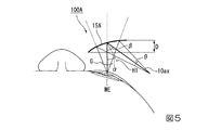
ここで、画角を大きくする場合に生じる問題について比較例を参照しながら説明する。図4、5は比較例に係るHMD100Aの概略構成を示す図であり、図4はHMD100Aにおいて画角を小さくする場合を示し、図5はHMD100Aにおいて画角を大きくする場合を示す。比較例に係るHMD100Aは、画像光Gを凹面ミラー15Aのみで使用者Mの眼MEに導く点で本実施形態のHMD300と異なる。なお、図4,5において、使用者Mの眼MEの瞳孔中心を通り、かつ観察される画像光Gの中心画角となる光線が通る経路を光軸10axとする。
Incidentally, in recent years, the HMD has been required to have a wider angle of view.
Here, a problem that occurs when the angle of view is increased will be described with reference to a comparative example. 4 and 5 are diagrams showing a schematic configuration of the
図4に示すように、凹面ミラー15Aの曲面は、使用者Mの鼻側では顔に近く、耳側では顔から離れるように配置される。画角θが大きくなると、図5に示すように、凹面ミラー15Aの突出量(以下、ミラー突出量Dと称す)が大きくなる。ミラー突出量Dが大きくなると外観デザインが損なわれるため、好ましくない。
As shown in FIG. 4, the curved surface of the
そこで、画角θを維持した状態でミラー突出量Dを小さくすることが考えられる。このように画角θを維持した状態でミラー突出量Dを小さくする手法として凹面ミラー15Aの傾斜角αを小さくすることが考えられる。ここで、傾斜角αとは、凹面ミラー15Aのミラー面法線H1と光軸10axとが成す角度である。
Therefore, it is conceivable to reduce the mirror protrusion amount D while maintaining the angle of view θ. As a method for reducing the mirror protrusion amount D while maintaining the angle of view θ as described above, it is conceivable to reduce the inclination angle α of the
しかしながら、図5から分かるように、傾斜角αを小さくすると、凹面ミラー15Aによる光軸10axの偏向角βが小さくなる。これにより、画像生成部11Aやリレー光学系12Aが使用者Mの頭部に近づくことで接触するといった問題が生じる。
However, as can be seen from FIG. 5, when the inclination angle α is decreased, the deflection angle β of the optical axis 10ax by the
これに対し、本実施形態のHMD300によれば、プリズム光学素子13の光屈折面16によって画像光Gを屈折させることができる。すなわち、上記ミラー突出量Dを抑えるために上記傾斜角αを小さくした場合でも、光屈折面16によって画像光Gを屈折させることで光軸100axを折り曲げて画像生成部11及びリレー光学系12を使用者Mの頭部に接触しない位置に位置させることができる。
On the other hand, according to the
例えば、図5において傾斜角αを30度としなければならない場合でも、本実施形態によればプリズム光学素子13を用いることで傾斜角αを15度に抑えることができる。また、図4に示した偏向角βを60度程度とした場合であっても、画像生成部11及びリレー光学系12が使用者Mの頭部に接触することがない。
For example, even when the inclination angle α has to be 30 degrees in FIG. 5, according to the present embodiment, the inclination angle α can be suppressed to 15 degrees by using the prism
例えば水平画角40度の虚像を観察可能とする場合、図4に示したような凹面ミラー15Aだけの構成ではミラー突出量Dが約17mmとなるが、本実施形態のようにプリズム光学素子13を用いた構成によればミラー突出量Dを約10mmまで薄くすることができる。
For example, when a virtual image with a horizontal angle of view of 40 degrees can be observed, the mirror protrusion amount D is about 17 mm with the configuration of only the
本実施形態によれば、プリズム光学素子13を用いることによってミラー突出量Dが小さくなるので、使用者Mの眼MEの前に位置する部材の厚さを薄くすることでHMD300の外観デザインを向上させることができる。
したがって、使用者Mの頭部への接触を抑制しつつ、外観を損なうことなく大きな画像を視認させることが可能なHMD300を提供することができる。
According to the present embodiment, since the mirror protrusion amount D is reduced by using the prism
Therefore, it is possible to provide the
(第二実施形態)
続いて、第二実施形態に係る画像表示部について説明する。図6は本実施形態の画像表示部210の各部の構成を示す平面図である。なお、図6において、上記実施形態と共通の部材については同じ符号を付し、その詳細については説明を省略する。図6では、画像生成部11の各画素から射出される画像光Gの主光線のみを図示している。
(Second embodiment)
Next, the image display unit according to the second embodiment will be described. FIG. 6 is a plan view showing the configuration of each part of the
本実施形態の画像表示部210は、図6に示すように、画像生成部11と、リレー光学系112と、プリズム光学素子13と、を備えている。本実施形態において、リレー光学系112は、画像生成部11とプリズム光学素子13との間に設けられた反射ミラー50を含んでいる。反射ミラー50は、画像光Gを反射することで光軸100axを折り曲げる。
As shown in FIG. 6, the
具体的に、リレー光学系112は、第1レンズ112aと、第2レンズ112bと、第3レンズ112cと、第4レンズ112dと、反射ミラー50とを含む。反射ミラー50は、第2レンズ112bと第3レンズ112cとの間に配置される。
Specifically, the relay
画像光Gは、第1レンズ112aと第2レンズ112bとを透過した後、反射ミラー50で反射されて第3レンズ112cと第4レンズ112dを透過する。これにより、画像光Gの光軸100axは反射ミラー50によって使用者Mの顔の輪郭に沿って折り曲げられたものとなる。よって、リレー光学系112及び画像生成部11が使用者Mの顔に沿って配置されるようになるので、小型化が図られるとともに優れた外観デザインを有する画像表示部210を提供することができる。よって、この画像表示部210を備えたHMD自体も小型且つデザイン性に優れたものとなる。
The image light G passes through the
(第三実施形態)
続いて、第三実施形態に係る画像表示部について説明する。図7は本実施形態の画像表示部310の各部の構成を示す平面図である。なお、図7において、上記実施形態と共通の部材については同じ符号を付し、その詳細については説明を省略する。図7では、画像生成部11の各画素から射出される画像光Gの主光線のみを図示している。
(Third embodiment)
Next, the image display unit according to the third embodiment will be described. FIG. 7 is a plan view showing the configuration of each part of the
上記第一、第二実施形態では、反射型のHMDに用いる画像表示装置を例に挙げたが、本実施形態の画像表示部は外界に画像光を重畳させるいわゆるシースルー型のHMDに用いられる点で異なる。 In the first and second embodiments, the image display device used for the reflection type HMD has been described as an example. It is different.
本実施形態の画像表示部310は、図7に示すように、画像生成部11と、リレー光学系112と、プリズム光学素子113と、を備えている。
本実施形態において、プリズム光学素子113は、プリズム部材14と、プリズム部材(第2のプリズム部材)20と、部分反射膜からなる凹面ミラー115とを含む。なお、凹面ミラー115を構成する部分反射膜としては、例えば、ハーフミラーを用いることができる。ハーフミラーとしては、金属を極薄く製膜して入射光の強度の一部を透過させる金属薄膜を用いることができる。
As shown in FIG. 7, the
In the present embodiment, the prism
なお、ハーフミラーを構成する金属薄膜は光の吸収も大きいため、誘電体多層膜を用いて凹面ミラー115を形成してもよい。この場合、凹面ミラー115は振幅分割型の反射膜から構成されたものとなり、画像光Gを効率良く反射させることができる。
In addition, since the metal thin film which comprises a half mirror also has large light absorption, you may form the
また、凹面ミラー115としては、特定の波長だけを反射(回折)させる体積ホログラム層を用いてもよい。この場合、凹面ミラー115は波長分割型の反射膜から構成されたものとなり、画像光Gに含まれる所望の波長帯の光を効率良く反射させることができる。
Further, as the
プリズム部材20は、凹面ミラー115のプリズム部材14と反対側に設けられる。プリズム部材20は、例えば、光学樹脂或いは光学ガラスから構成され、プリズム部材14と略同一の屈折率を有する。
The
プリズム部材20は、凹面ミラー115と反対側に光屈折面16と平行、すなわち平面からなる外面側光屈折面(第2の光屈折面)21を有している。
The
ここで、使用者Mの眼MEの前にプリズム部材14のみが配置されていると外界が歪んで見えてしまう。これに対して、本実施形態によれば、凹面ミラー115の外界側にプリズム部材20を配置することで、外界からの光の光路を補償することで外界が歪んで見えるのを抑制している。
Here, if only the
具体的に、凹面ミラー115に対して眼ME側の光学樹脂(プリズム部材14)と外界側の光学樹脂(プリズム部材20)の屈折率とを略同じとすることで、プリズム部材14の曲面17で光が屈折しないようにしている。
Specifically, the refractive index of the optical resin (prism member 14) on the eye ME side and the optical resin (prism member 20) on the outside world with respect to the
上記第一実施形態で説明したように、水平画角が40度程度の大きな虚像を観察する場合、プリズム光学素子113のミラー突出量Dは10mm程度になる。このように厚いプリズム部材を通して外界を見る場合、シースルー像に歪みが生じやすくなる。
As described in the first embodiment, when a large virtual image having a horizontal angle of view of about 40 degrees is observed, the mirror protrusion amount D of the prism
これに対し、本実施形態のプリズム光学素子113によれば外界からの光入射面と光出射面とが平行な平面であるため、外界からプリズム光学素子113に入射する光線の角度と、プリズム光学素子113で屈折された後に出射される際の光線の角度とが変化しない。そのため、HMDの使用者Mは、凹面ミラー115越しに見える外界の像(シースルー像G1)に歪みが生じないため、使用時における疲労感及び不快感が低減される。
したがって、本実施形態のHMDの使用者Mによれば、歪みのないシースルー像G1に画像生成部11からの画像光Gを重畳させて視認することができる。
On the other hand, according to the prism
Therefore, according to the user M of the HMD of the present embodiment, the image light G from the
なお、本発明の技術範囲は上記実施形態に限定されるものではなく、本発明の趣旨を逸脱しない範囲において種々の変更を加えることが可能である。 The technical scope of the present invention is not limited to the above embodiment, and various modifications can be made without departing from the spirit of the present invention.
11,11A…画像生成部、12,12A,112…リレー光学系(導光光学系)、13,113…プリズム光学素子、14…プリズム部材(第1のプリズム部材)、15,15A,115…凹面ミラー、16…光屈折面、20…プリズム部材(第2のプリズム部材)、50…反射ミラー、300,100A…HMD(画像表示装置)、100ax…光軸、G…画像光、M…使用者、ME…眼。
DESCRIPTION OF
Claims (6)
前記画像光が入射するプリズム光学素子と、を備え、
前記プリズム光学素子は、
平面形状の第1の光屈折面が設けられた第1のプリズム部材と、
前記プリズム部材の前記第1の光屈折面と反対側に設けられ、前記第1の光屈折面から遠ざかる方向に凸状となる凹面ミラーと、を有し、
前記プリズム光学素子は、前記画像光が前記第1の光屈折面から入射し、前記凹面ミラーで反射するように配置されている
ことを特徴とする画像表示装置。 An image generator for emitting image light;
A prism optical element on which the image light is incident,
The prism optical element is
A first prism member provided with a planar first photorefractive surface;
A concave mirror provided on the opposite side of the prism member from the first light refracting surface and convex in a direction away from the first light refracting surface,
The image display apparatus, wherein the prism optical element is arranged so that the image light is incident from the first light refracting surface and reflected by the concave mirror.
前記導光光学系は、複数のレンズを有する
ことを特徴とする請求項1に記載の画像表示装置。 A light guide optical system for guiding the image light to the prism optical element;
The image display device according to claim 1, wherein the light guide optical system includes a plurality of lenses.
ことを特徴とする請求項2に記載の画像表示装置。 The image display apparatus according to claim 2, wherein the light guide optical system includes a reflection mirror that is provided between the plurality of lenses and reflects the image light.
前記第2のプリズム部材は、前記凹面ミラーと反対側に前記第1の光屈折面と平行となるように設けられた第2の光屈折面を有しており、
前記凹面ミラーは、前記画像光の少なくとも一部を反射し、外界の光の少なくとも一部透過する部分反射膜である
ことを特徴とする請求項1乃至3の何れか一項に記載の画像表示装置。 The prism optical element further includes a second prism member provided on the opposite side of the concave mirror from the first prism member and provided to have the same refractive index as the first prism member,
The second prism member has a second light refracting surface provided on the opposite side to the concave mirror so as to be parallel to the first light refracting surface,
4. The image display according to claim 1, wherein the concave mirror is a partial reflection film that reflects at least a part of the image light and transmits at least a part of light in the outside world. 5. apparatus.
ことを特徴とする請求項4に記載の画像表示装置。 The image display device according to claim 4, wherein the partial reflection film is an amplitude division type reflection film.
ことを特徴とする請求項4に記載の画像表示装置。 The image display device according to claim 4, wherein the partial reflection film is a wavelength division type reflection film.
Priority Applications (2)
| Application Number | Priority Date | Filing Date | Title |
|---|---|---|---|
| JP2016059676A JP6812649B2 (en) | 2016-03-24 | 2016-03-24 | Image display device |
| US15/460,646 US10634915B2 (en) | 2016-03-24 | 2017-03-16 | Image display device |
Applications Claiming Priority (1)
| Application Number | Priority Date | Filing Date | Title |
|---|---|---|---|
| JP2016059676A JP6812649B2 (en) | 2016-03-24 | 2016-03-24 | Image display device |
Publications (2)
| Publication Number | Publication Date |
|---|---|
| JP2017173573A true JP2017173573A (en) | 2017-09-28 |
| JP6812649B2 JP6812649B2 (en) | 2021-01-13 |
Family
ID=59896469
Family Applications (1)
| Application Number | Title | Priority Date | Filing Date |
|---|---|---|---|
| JP2016059676A Active JP6812649B2 (en) | 2016-03-24 | 2016-03-24 | Image display device |
Country Status (2)
| Country | Link |
|---|---|
| US (1) | US10634915B2 (en) |
| JP (1) | JP6812649B2 (en) |
Cited By (5)
| Publication number | Priority date | Publication date | Assignee | Title |
|---|---|---|---|---|
| JP2019113839A (en) * | 2017-12-25 | 2019-07-11 | 株式会社リコー | Head-mounted type display unit and display system |
| KR20210051717A (en) * | 2019-10-31 | 2021-05-10 | 이성민 | Optical System of Near to Eye Display |
| US11067804B2 (en) | 2018-02-23 | 2021-07-20 | Seiko Epson Corporation | Virtual image display device |
| CN113366376A (en) * | 2019-02-13 | 2021-09-07 | 株式会社籁天那 | Enhanced in-use optical device capable of providing close-range enhanced in-use image |
| JP2021524067A (en) * | 2018-05-17 | 2021-09-09 | プラゼン カンパニー リミテッドPrazen Co.,Ltd. | Augmented reality display device |
Families Citing this family (2)
| Publication number | Priority date | Publication date | Assignee | Title |
|---|---|---|---|---|
| KR102045476B1 (en) * | 2018-06-28 | 2019-11-15 | 옵티시스 주식회사 | Optical connector |
| IL305075A (en) * | 2023-08-08 | 2025-03-01 | Elbit Systems Ltd | Head-mounted image display system |
Citations (11)
| Publication number | Priority date | Publication date | Assignee | Title |
|---|---|---|---|---|
| JPH03501173A (en) * | 1988-06-15 | 1991-03-14 | ジーイーシー マーコニ リミテッド | heads-up display device |
| JPH08184780A (en) * | 1995-01-04 | 1996-07-16 | Olympus Optical Co Ltd | Picture display device |
| JPH10301055A (en) * | 1997-04-25 | 1998-11-13 | Sony Corp | Image display device |
| JPH11112909A (en) * | 1997-10-01 | 1999-04-23 | Sharp Corp | Head-mounted display |
| US6111701A (en) * | 1999-07-14 | 2000-08-29 | Rockwell Collins, Inc. | Chromatic aberration corrected multi-color head-up display system |
| JP2000511306A (en) * | 1996-10-08 | 2000-08-29 | ザ マイクロオプティカル コーポレイション | Image combining system for eyeglasses and face mask |
| JP2001066544A (en) * | 1999-08-31 | 2001-03-16 | Minolta Co Ltd | Video display device |
| JP2003502711A (en) * | 1999-06-21 | 2003-01-21 | ザ マイクロオプティカル コーポレイション | Eyepiece display lens system using off-axis optical design |
| US20120081800A1 (en) * | 2009-04-20 | 2012-04-05 | Dewen Cheng | Optical see-through free-form head-mounted display |
| CN103439793A (en) * | 2013-07-18 | 2013-12-11 | 成都理想境界科技有限公司 | Hmd |
| JP2015125222A (en) * | 2013-12-26 | 2015-07-06 | セイコーエプソン株式会社 | Virtual image display device |
Family Cites Families (11)
| Publication number | Priority date | Publication date | Assignee | Title |
|---|---|---|---|---|
| JPH05134208A (en) | 1991-11-12 | 1993-05-28 | Olympus Optical Co Ltd | Image observation device |
| JP3597456B2 (en) | 1993-02-09 | 2004-12-08 | オリンパス株式会社 | Eccentric optical system and visual display device using the same |
| JP3212203B2 (en) | 1993-02-09 | 2001-09-25 | オリンパス光学工業株式会社 | Visual display device |
| JP3346640B2 (en) | 1994-02-07 | 2002-11-18 | オリンパス光学工業株式会社 | Video display device |
| JP3542214B2 (en) | 1995-12-22 | 2004-07-14 | オリンパス株式会社 | Image display device |
| JP3780026B2 (en) | 1996-01-08 | 2006-05-31 | キヤノン株式会社 | Image display device |
| US6563648B2 (en) * | 2000-10-20 | 2003-05-13 | Three-Five Systems, Inc. | Compact wide field of view imaging system |
| IL173361A (en) * | 2005-09-12 | 2012-03-29 | Elbit Systems Ltd | Near eye display system |
| JP5646238B2 (en) * | 2010-07-27 | 2014-12-24 | オリンパス株式会社 | Image display device |
| JP5653816B2 (en) | 2011-03-29 | 2015-01-14 | オリンパス株式会社 | Image display apparatus having decentered optical system |
| KR102485447B1 (en) * | 2017-08-09 | 2023-01-05 | 삼성전자주식회사 | Optical window system and see-through type display apparatus including the same |
-
2016
- 2016-03-24 JP JP2016059676A patent/JP6812649B2/en active Active
-
2017
- 2017-03-16 US US15/460,646 patent/US10634915B2/en active Active
Patent Citations (11)
| Publication number | Priority date | Publication date | Assignee | Title |
|---|---|---|---|---|
| JPH03501173A (en) * | 1988-06-15 | 1991-03-14 | ジーイーシー マーコニ リミテッド | heads-up display device |
| JPH08184780A (en) * | 1995-01-04 | 1996-07-16 | Olympus Optical Co Ltd | Picture display device |
| JP2000511306A (en) * | 1996-10-08 | 2000-08-29 | ザ マイクロオプティカル コーポレイション | Image combining system for eyeglasses and face mask |
| JPH10301055A (en) * | 1997-04-25 | 1998-11-13 | Sony Corp | Image display device |
| JPH11112909A (en) * | 1997-10-01 | 1999-04-23 | Sharp Corp | Head-mounted display |
| JP2003502711A (en) * | 1999-06-21 | 2003-01-21 | ザ マイクロオプティカル コーポレイション | Eyepiece display lens system using off-axis optical design |
| US6111701A (en) * | 1999-07-14 | 2000-08-29 | Rockwell Collins, Inc. | Chromatic aberration corrected multi-color head-up display system |
| JP2001066544A (en) * | 1999-08-31 | 2001-03-16 | Minolta Co Ltd | Video display device |
| US20120081800A1 (en) * | 2009-04-20 | 2012-04-05 | Dewen Cheng | Optical see-through free-form head-mounted display |
| CN103439793A (en) * | 2013-07-18 | 2013-12-11 | 成都理想境界科技有限公司 | Hmd |
| JP2015125222A (en) * | 2013-12-26 | 2015-07-06 | セイコーエプソン株式会社 | Virtual image display device |
Cited By (8)
| Publication number | Priority date | Publication date | Assignee | Title |
|---|---|---|---|---|
| JP2019113839A (en) * | 2017-12-25 | 2019-07-11 | 株式会社リコー | Head-mounted type display unit and display system |
| JP7200637B2 (en) | 2017-12-25 | 2023-01-10 | 株式会社リコー | Head-mounted display and display system |
| US11067804B2 (en) | 2018-02-23 | 2021-07-20 | Seiko Epson Corporation | Virtual image display device |
| JP2021524067A (en) * | 2018-05-17 | 2021-09-09 | プラゼン カンパニー リミテッドPrazen Co.,Ltd. | Augmented reality display device |
| CN113366376A (en) * | 2019-02-13 | 2021-09-07 | 株式会社籁天那 | Enhanced in-use optical device capable of providing close-range enhanced in-use image |
| CN113366376B (en) * | 2019-02-13 | 2023-11-03 | 株式会社籁天那 | Enhanced on-the-fly optical device capable of providing enhanced on-the-fly images at close range |
| KR20210051717A (en) * | 2019-10-31 | 2021-05-10 | 이성민 | Optical System of Near to Eye Display |
| KR102412293B1 (en) | 2019-10-31 | 2022-06-22 | 이성민 | Optical System of Near to Eye Display |
Also Published As
| Publication number | Publication date |
|---|---|
| US20170276946A1 (en) | 2017-09-28 |
| JP6812649B2 (en) | 2021-01-13 |
| US10634915B2 (en) | 2020-04-28 |
Similar Documents
| Publication | Publication Date | Title |
|---|---|---|
| JP6661885B2 (en) | Image display device | |
| JP6994940B2 (en) | Head-mounted imaging device using optical coupling | |
| JP6812649B2 (en) | Image display device | |
| JP6595619B2 (en) | Efficient thin curved eyepiece for see-through head wearable display | |
| JP6774429B2 (en) | Addition of prescription modifications to eyepieces for see-through headwearable displays | |
| TWI570443B (en) | Lightguide with multiple in-coupling holograms for head wearable display | |
| JP5290091B2 (en) | Eyeglass-type image display device | |
| JP2021060625A (en) | Spectacle lens for display device that can be fitted on head of user and generates image | |
| JP6402991B2 (en) | Image display device | |
| EP3203304A1 (en) | Image display device | |
| JP2011053367A (en) | Spectacles-type image display device | |
| JP2002287077A (en) | Video display device | |
| US11067804B2 (en) | Virtual image display device | |
| JP2017534352A (en) | Imaging optics and smart glasses | |
| JP2018054977A (en) | Virtual image display device | |
| US20230100029A1 (en) | Light guide, optical unit, virtual image display device, and head-mounted display | |
| CN115552295B (en) | Eyebox steering and field of view expansion using beam steering elements | |
| KR102386259B1 (en) | Optical device for augmented reality having visual acuity correction function | |
| KR102438997B1 (en) | Optical device for augmented reality with vision correction function | |
| JP7786092B2 (en) | Propagation optical system, optical system, virtual image display device and head-mounted display | |
| JP2004029544A (en) | Hologram combiner optical system and information display device | |
| JP4395673B2 (en) | Video display device | |
| CN109946840B (en) | display device | |
| JP2020160275A (en) | Virtual image display device | |
| KR102353010B1 (en) | Optical device for augmented reality having visual acuity correction function |
Legal Events
| Date | Code | Title | Description |
|---|---|---|---|
| RD05 | Notification of revocation of power of attorney |
Free format text: JAPANESE INTERMEDIATE CODE: A7425 Effective date: 20180907 |
|
| RD03 | Notification of appointment of power of attorney |
Free format text: JAPANESE INTERMEDIATE CODE: A7423 Effective date: 20181119 |
|
| A621 | Written request for application examination |
Free format text: JAPANESE INTERMEDIATE CODE: A621 Effective date: 20190313 |
|
| A977 | Report on retrieval |
Free format text: JAPANESE INTERMEDIATE CODE: A971007 Effective date: 20200122 |
|
| A131 | Notification of reasons for refusal |
Free format text: JAPANESE INTERMEDIATE CODE: A131 Effective date: 20200128 |
|
| A521 | Request for written amendment filed |
Free format text: JAPANESE INTERMEDIATE CODE: A523 Effective date: 20200325 |
|
| A131 | Notification of reasons for refusal |
Free format text: JAPANESE INTERMEDIATE CODE: A131 Effective date: 20200630 |
|
| RD07 | Notification of extinguishment of power of attorney |
Free format text: JAPANESE INTERMEDIATE CODE: A7427 Effective date: 20200803 |
|
| A521 | Request for written amendment filed |
Free format text: JAPANESE INTERMEDIATE CODE: A523 Effective date: 20200824 |
|
| TRDD | Decision of grant or rejection written | ||
| A01 | Written decision to grant a patent or to grant a registration (utility model) |
Free format text: JAPANESE INTERMEDIATE CODE: A01 Effective date: 20201117 |
|
| A61 | First payment of annual fees (during grant procedure) |
Free format text: JAPANESE INTERMEDIATE CODE: A61 Effective date: 20201130 |
|
| R150 | Certificate of patent or registration of utility model |
Ref document number: 6812649 Country of ref document: JP Free format text: JAPANESE INTERMEDIATE CODE: R150 |