JP2017174111A - In-vehicle gateway device, storage control method, and program - Google Patents
In-vehicle gateway device, storage control method, and program Download PDFInfo
- Publication number
- JP2017174111A JP2017174111A JP2016058798A JP2016058798A JP2017174111A JP 2017174111 A JP2017174111 A JP 2017174111A JP 2016058798 A JP2016058798 A JP 2016058798A JP 2016058798 A JP2016058798 A JP 2016058798A JP 2017174111 A JP2017174111 A JP 2017174111A
- Authority
- JP
- Japan
- Prior art keywords
- data
- unit
- vehicle
- gateway device
- ecu
- Prior art date
- Legal status (The legal status is an assumption and is not a legal conclusion. Google has not performed a legal analysis and makes no representation as to the accuracy of the status listed.)
- Pending
Links
Images









Classifications
-
- G—PHYSICS
- G07—CHECKING-DEVICES
- G07C—TIME OR ATTENDANCE REGISTERS; REGISTERING OR INDICATING THE WORKING OF MACHINES; GENERATING RANDOM NUMBERS; VOTING OR LOTTERY APPARATUS; ARRANGEMENTS, SYSTEMS OR APPARATUS FOR CHECKING NOT PROVIDED FOR ELSEWHERE
- G07C5/00—Registering or indicating the working of vehicles
- G07C5/08—Registering or indicating performance data other than driving, working, idle, or waiting time, with or without registering driving, working, idle or waiting time
- G07C5/0808—Diagnosing performance data
-
- G—PHYSICS
- G06—COMPUTING OR CALCULATING; COUNTING
- G06F—ELECTRIC DIGITAL DATA PROCESSING
- G06F13/00—Interconnection of, or transfer of information or other signals between, memories, input/output devices or central processing units
- G06F13/38—Information transfer, e.g. on bus
- G06F13/382—Information transfer, e.g. on bus using universal interface adapter
- G06F13/387—Information transfer, e.g. on bus using universal interface adapter for adaptation of different data processing systems to different peripheral devices, e.g. protocol converters for incompatible systems, open system
-
- G—PHYSICS
- G06—COMPUTING OR CALCULATING; COUNTING
- G06F—ELECTRIC DIGITAL DATA PROCESSING
- G06F13/00—Interconnection of, or transfer of information or other signals between, memories, input/output devices or central processing units
- G06F13/38—Information transfer, e.g. on bus
- G06F13/40—Bus structure
- G06F13/4004—Coupling between buses
- G06F13/4027—Coupling between buses using bus bridges
-
- G—PHYSICS
- G07—CHECKING-DEVICES
- G07C—TIME OR ATTENDANCE REGISTERS; REGISTERING OR INDICATING THE WORKING OF MACHINES; GENERATING RANDOM NUMBERS; VOTING OR LOTTERY APPARATUS; ARRANGEMENTS, SYSTEMS OR APPARATUS FOR CHECKING NOT PROVIDED FOR ELSEWHERE
- G07C5/00—Registering or indicating the working of vehicles
- G07C5/008—Registering or indicating the working of vehicles communicating information to a remotely located station
-
- G—PHYSICS
- G07—CHECKING-DEVICES
- G07C—TIME OR ATTENDANCE REGISTERS; REGISTERING OR INDICATING THE WORKING OF MACHINES; GENERATING RANDOM NUMBERS; VOTING OR LOTTERY APPARATUS; ARRANGEMENTS, SYSTEMS OR APPARATUS FOR CHECKING NOT PROVIDED FOR ELSEWHERE
- G07C5/00—Registering or indicating the working of vehicles
- G07C5/08—Registering or indicating performance data other than driving, working, idle, or waiting time, with or without registering driving, working, idle or waiting time
- G07C5/0841—Registering performance data
- G07C5/085—Registering performance data using electronic data carriers
-
- H—ELECTRICITY
- H04—ELECTRIC COMMUNICATION TECHNIQUE
- H04L—TRANSMISSION OF DIGITAL INFORMATION, e.g. TELEGRAPHIC COMMUNICATION
- H04L12/00—Data switching networks
- H04L12/28—Data switching networks characterised by path configuration, e.g. LAN [Local Area Networks] or WAN [Wide Area Networks]
- H04L12/40—Bus networks
- H04L12/40006—Architecture of a communication node
-
- H—ELECTRICITY
- H04—ELECTRIC COMMUNICATION TECHNIQUE
- H04L—TRANSMISSION OF DIGITAL INFORMATION, e.g. TELEGRAPHIC COMMUNICATION
- H04L12/00—Data switching networks
- H04L12/28—Data switching networks characterised by path configuration, e.g. LAN [Local Area Networks] or WAN [Wide Area Networks]
- H04L12/46—Interconnection of networks
- H04L12/4604—LAN interconnection over a backbone network, e.g. Internet, Frame Relay
- H04L12/462—LAN interconnection over a bridge based backbone
- H04L12/4625—Single bridge functionality, e.g. connection of two networks over a single bridge
-
- H—ELECTRICITY
- H04—ELECTRIC COMMUNICATION TECHNIQUE
- H04L—TRANSMISSION OF DIGITAL INFORMATION, e.g. TELEGRAPHIC COMMUNICATION
- H04L12/00—Data switching networks
- H04L12/66—Arrangements for connecting between networks having differing types of switching systems, e.g. gateways
-
- H—ELECTRICITY
- H04—ELECTRIC COMMUNICATION TECHNIQUE
- H04L—TRANSMISSION OF DIGITAL INFORMATION, e.g. TELEGRAPHIC COMMUNICATION
- H04L67/00—Network arrangements or protocols for supporting network services or applications
- H04L67/01—Protocols
- H04L67/12—Protocols specially adapted for proprietary or special-purpose networking environments, e.g. medical networks, sensor networks, networks in vehicles or remote metering networks
-
- H—ELECTRICITY
- H04—ELECTRIC COMMUNICATION TECHNIQUE
- H04L—TRANSMISSION OF DIGITAL INFORMATION, e.g. TELEGRAPHIC COMMUNICATION
- H04L9/00—Cryptographic mechanisms or cryptographic arrangements for secret or secure communications; Network security protocols
- H04L9/08—Key distribution or management, e.g. generation, sharing or updating, of cryptographic keys or passwords
- H04L9/088—Usage controlling of secret information, e.g. techniques for restricting cryptographic keys to pre-authorized uses, different access levels, validity of crypto-period, different key- or password length, or different strong and weak cryptographic algorithms
-
- H—ELECTRICITY
- H04—ELECTRIC COMMUNICATION TECHNIQUE
- H04L—TRANSMISSION OF DIGITAL INFORMATION, e.g. TELEGRAPHIC COMMUNICATION
- H04L9/00—Cryptographic mechanisms or cryptographic arrangements for secret or secure communications; Network security protocols
- H04L9/08—Key distribution or management, e.g. generation, sharing or updating, of cryptographic keys or passwords
- H04L9/0891—Revocation or update of secret information, e.g. encryption key update or rekeying
-
- H—ELECTRICITY
- H04—ELECTRIC COMMUNICATION TECHNIQUE
- H04L—TRANSMISSION OF DIGITAL INFORMATION, e.g. TELEGRAPHIC COMMUNICATION
- H04L9/00—Cryptographic mechanisms or cryptographic arrangements for secret or secure communications; Network security protocols
- H04L9/32—Cryptographic mechanisms or cryptographic arrangements for secret or secure communications; Network security protocols including means for verifying the identity or authority of a user of the system or for message authentication, e.g. authorization, entity authentication, data integrity or data verification, non-repudiation, key authentication or verification of credentials
-
- H—ELECTRICITY
- H04—ELECTRIC COMMUNICATION TECHNIQUE
- H04L—TRANSMISSION OF DIGITAL INFORMATION, e.g. TELEGRAPHIC COMMUNICATION
- H04L9/00—Cryptographic mechanisms or cryptographic arrangements for secret or secure communications; Network security protocols
- H04L9/32—Cryptographic mechanisms or cryptographic arrangements for secret or secure communications; Network security protocols including means for verifying the identity or authority of a user of the system or for message authentication, e.g. authorization, entity authentication, data integrity or data verification, non-repudiation, key authentication or verification of credentials
- H04L9/3226—Cryptographic mechanisms or cryptographic arrangements for secret or secure communications; Network security protocols including means for verifying the identity or authority of a user of the system or for message authentication, e.g. authorization, entity authentication, data integrity or data verification, non-repudiation, key authentication or verification of credentials using a predetermined code, e.g. password, passphrase or PIN
-
- H—ELECTRICITY
- H04—ELECTRIC COMMUNICATION TECHNIQUE
- H04L—TRANSMISSION OF DIGITAL INFORMATION, e.g. TELEGRAPHIC COMMUNICATION
- H04L12/00—Data switching networks
- H04L12/28—Data switching networks characterised by path configuration, e.g. LAN [Local Area Networks] or WAN [Wide Area Networks]
- H04L12/40—Bus networks
- H04L2012/40267—Bus for use in transportation systems
- H04L2012/40273—Bus for use in transportation systems the transportation system being a vehicle
-
- H—ELECTRICITY
- H04—ELECTRIC COMMUNICATION TECHNIQUE
- H04L—TRANSMISSION OF DIGITAL INFORMATION, e.g. TELEGRAPHIC COMMUNICATION
- H04L2209/00—Additional information or applications relating to cryptographic mechanisms or cryptographic arrangements for secret or secure communication H04L9/00
- H04L2209/84—Vehicles
Landscapes
- Engineering & Computer Science (AREA)
- Signal Processing (AREA)
- Computer Networks & Wireless Communication (AREA)
- Computer Security & Cryptography (AREA)
- General Physics & Mathematics (AREA)
- Physics & Mathematics (AREA)
- Theoretical Computer Science (AREA)
- General Engineering & Computer Science (AREA)
- Health & Medical Sciences (AREA)
- Computing Systems (AREA)
- General Health & Medical Sciences (AREA)
- Medical Informatics (AREA)
- Computer Hardware Design (AREA)
- Small-Scale Networks (AREA)
Abstract
【課題】蓄積するデータを保護しながら、データの用途に応じてその出力を制限できる車載ゲートウェイ装置、蓄積制御方法およびプログラムを提供する。【解決手段】実施形態の車載ゲートウェイ装置100は、車載システムに搭載される車載ゲートウェイ装置であって、車載システムに含まれるECU(電子制御ユニット)が出力するデータを蓄積する蓄積部130と、少なくとも一つのECUが接続される内部通信処理部を含む複数の内部通信処理部111−115と、複数の内部通信処理部111−115の間でデータを転送するとともに、転送したデータの少なくとも一部を蓄積部130に蓄積可能に出力するルーティング処理部120と、蓄積部130に蓄積するデータと蓄積部130から出力するデータとの少なくともいずれかを所定のルールに従って加工または選別する蓄積制御部140と、を備える。【選択図】図2An in-vehicle gateway device, an accumulation control method, and a program capable of limiting the output according to the use of data while protecting the accumulated data. An in-vehicle gateway device according to an embodiment is an in-vehicle gateway device mounted in an in-vehicle system, and includes at least a storage unit that accumulates data output from an ECU (electronic control unit) included in the in-vehicle system. Data is transferred between a plurality of internal communication processing units 111-115 including an internal communication processing unit to which one ECU is connected and a plurality of internal communication processing units 111-115, and at least a part of the transferred data is transferred A routing processing unit 120 that outputs to the storage unit 130 so that it can be stored; a storage control unit 140 that processes or sorts at least one of data stored in the storage unit 130 and data output from the storage unit 130 according to a predetermined rule; Is provided. [Selection] Figure 2
Description
本発明の実施形態は、車載ゲートウェイ装置、蓄積制御方法およびプログラムに関する。 Embodiments described herein relate generally to an in-vehicle gateway device, a storage control method, and a program.
従来、車載システムにおいてデータを記録するための記録装置が存在した。それらの記録装置は、ドライブレコーダに代表されるようにカメラで撮影した映像データをハードディスクドライブ(HDD)やSDカードなどの記録媒体に記録する機能を備えている。また、車載システムに搭載された電子制御ユニット(ECU:Electronic Control Unit)が出力するデータを収集し、車外のサーバにログとして記録するシステムも提案されている。 Conventionally, there has been a recording device for recording data in an in-vehicle system. These recording devices have a function of recording video data captured by a camera on a recording medium such as a hard disk drive (HDD) or an SD card, as represented by a drive recorder. There has also been proposed a system that collects data output from an electronic control unit (ECU) mounted on an in-vehicle system and records it as a log on a server outside the vehicle.
しかし、従来の技術では、車載システムが外部装置とネットワークを介して接続され、不正な外部装置から攻撃を受けたり、車載システムの内部に悪意のある装置やプログラムが存在したりすることを想定していない。このため、攻撃者または悪意ある利用者から記録媒体に記録されたデータを不正に取得されたり、不正に改変されたり、不正に消去されたりする脅威には対応していなかった。 However, the conventional technology assumes that an in-vehicle system is connected to an external device via a network and is attacked by an unauthorized external device, or a malicious device or program exists inside the in-vehicle system. Not. For this reason, it has not coped with threats in which data recorded on a recording medium from an attacker or a malicious user is illegally obtained, illegally modified, or illegally erased.
また、車載システム内部で発生した異常やセキュリティ上の検証処理が失敗したことを検出し、ログに記録する仕組みも提案されている。しかしこの場合も、車載システム内部の不正モジュールや不正プログラムから記録媒体に記録されたデータを不正に操作されることは想定していない。このため、セキュリティ事故が発生したとしても、その痕跡を残すための具体的な実現方法は明らかになっていなかった。 In addition, a mechanism has been proposed in which an abnormality occurring in the in-vehicle system or a failure in security verification processing is detected and recorded in a log. However, even in this case, it is not assumed that the data recorded on the recording medium is illegally operated from the unauthorized module or unauthorized program in the in-vehicle system. For this reason, even if a security accident occurs, the specific implementation method to leave the trace has not been clarified.
また、ECUが出力するデータには完成車メーカのノウハウが含まれているため、完成車メーカにとって保護対象のデータとなり得る。例えば、完成車メーカ自身もしくは保険会社や、裁判所などの法的機関など完成車メーカが許可した第3者にはECUが出力して車載システム内部に蓄積した全てのデータを開示する一方で、一般ユーザや競合の完成車メーカに対してはデータの取得や解析を防止したり、蓄積したデータを部分的に公開したりする仕組みが求められる。しかし、その具体的な実現方法は明らかになっていなかった。 Further, since the data output by the ECU includes the know-how of the complete vehicle manufacturer, it can be data to be protected for the complete vehicle manufacturer. For example, while disclosing all the data output by the ECU and stored in the in-vehicle system to the third party authorized by the completed vehicle manufacturer such as the completed vehicle manufacturer itself or an insurance company or a legal institution such as a court, For users and competing vehicle manufacturers, there is a need for a mechanism that prevents data acquisition and analysis, and partially discloses accumulated data. However, the specific implementation method has not been clarified.
以上のことから、ECUが出力するデータを車載システム内部に蓄積する場合、蓄積するデータを保護しながら、データの用途に応じてその出力を制限できる仕組みを構築することが求められる。 From the above, when storing the data output by the ECU in the in-vehicle system, it is required to construct a mechanism that can limit the output according to the use of the data while protecting the stored data.
本発明が解決しようとする課題は、蓄積するデータを保護しながら、データの用途に応じてその出力を制限できる車載ゲートウェイ装置、蓄積制御方法およびプログラムを提供することである。 The problem to be solved by the present invention is to provide an in-vehicle gateway device, a storage control method, and a program capable of limiting the output according to the use of data while protecting the stored data.
実施形態の車載ゲートウェイ装置は、車載システムに搭載される車載ゲートウェイ装置であって、蓄積部と、複数の内部通信処理部と、ルーティング処理部と、蓄積制御部と、を備える。蓄積部は、前記車載システムに含まれる電子制御ユニットが出力するデータを蓄積する。複数の内部通信処理部は、少なくとも一つの電子制御ユニットが接続される内部通信処理部を含む。ルーティング処理部は、前記複数の内部通信処理部の間でデータを転送するとともに、転送したデータの少なくとも一部を前記蓄積部に蓄積可能に出力する。蓄積制御部は、前記蓄積部に蓄積するデータと前記蓄積部から出力するデータとの少なくともいずれかを所定のルールに従って加工または選別する。 The in-vehicle gateway device according to the embodiment is an in-vehicle gateway device mounted in an in-vehicle system, and includes a storage unit, a plurality of internal communication processing units, a routing processing unit, and a storage control unit. The accumulation unit accumulates data output from the electronic control unit included in the in-vehicle system. The plurality of internal communication processing units include an internal communication processing unit to which at least one electronic control unit is connected. The routing processing unit transfers data between the plurality of internal communication processing units, and outputs at least a part of the transferred data to the storage unit so that the data can be stored. The accumulation control unit processes or sorts at least one of data accumulated in the accumulation unit and data output from the accumulation unit according to a predetermined rule.
実施形態の車載ゲートウェイ装置は、ECUが出力するデータを効率よく蓄積し、改変されることを防止しつつ、蓄積したデータをセキュリティ事故が発生した後などに選択的に出力するものである。以下では、このような車載ゲートウェイ装置の具体的な構成例について、図面を参照しながら詳細に説明する。 The in-vehicle gateway device according to the embodiment accumulates data output from the ECU efficiently and prevents it from being altered, and selectively outputs the accumulated data after a security accident occurs. Below, the specific structural example of such a vehicle-mounted gateway apparatus is demonstrated in detail, referring drawings.
<第1実施形態>
まず、実施形態の車載ゲートウェイ装置を搭載した車載システムについて説明する。図1は、車載システム10の概略構成を示すブロック図である。この車載システム10は、例えば自動車やバス、トラック、バイクなどの車両に搭載されることを想定している。なお、図1に示す車載システム10の構成は一例であり、これに限らない。例えば、車載システム10に含まれるECUの数や各ECUの役割分担、車載ゲートウェイ装置100との接続関係などは、車両の構成などに応じて任意に変更することができる。また、信頼性向上のために特定のECUを複数のバスに接続し、一方のバスが故障しても他方のバスでデータを送受信できる冗長な構成とすることもある。
<First Embodiment>
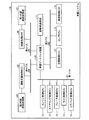
First, an in-vehicle system equipped with the in-vehicle gateway device of the embodiment will be described. FIG. 1 is a block diagram illustrating a schematic configuration of the in-
図1に示す車載システム10は、車載ゲートウェイ装置100と、診断用通信部11と、エンジン制御ECU12と、ステアリング制御ECU13と、ブレーキ制御ECU14と、ライト制御ECU15と、エアバッグ制御ECU16と、空調制御ECU17と、センサECU18と、座席制御ECU19と、映像処理ECU20と、第1外部通信処理部21と、運転支援制御ECU22と、第2外部通信処理部23とを備えている。
An in-
エンジン制御ECU12は、車両のエンジンを制御するECUである。ステアリング制御ECU13は、車両のステアリング操作を制御するECUである。ブレーキ制御ECU14は、車両のブレーキを制御するECUである。ライト制御ECU15は、車両のライト(電燈)の動作を制御するECUである。エアバッグ制御ECU16は、車両のエアバッグの動作を制御するECUである。
The engine control ECU 12 is an ECU that controls the engine of the vehicle. The
これらエンジン制御ECU12、ステアリング制御ECU13、ブレーキ制御ECU14、ライト制御ECU15およびエアバッグ制御ECU16は、例えば、CAN(Controller Area Network)の規格に準拠した第1バスB1に接続され、パワートレインCANと呼ばれるネットワークを構成する。このパワートレインCANの各ECUは、第1バスB1を介して、車載ゲートウェイ装置100に接続されている。
The
空調制御ECU17は、車両の空調を制御するECUである。センサECU18は、車両の温度センサや圧力センサなど車両内外の状態を計測する各種センサを含むECUである。座席制御ECU19は、車両の座席の位置を制御するECUである。
The air conditioning control ECU 17 is an ECU that controls the air conditioning of the vehicle. The sensor ECU 18 is an ECU including various sensors that measure the state inside and outside the vehicle, such as a temperature sensor and a pressure sensor of the vehicle. The
これら空調制御ECU17、センサECU18および座席制御ECU19は、例えば、CANの規格に準拠した第2バスB2に接続され、ボディCANと呼ばれるネットワークを構成する。このボディCANの各ECUは、第2バスB2を介して、車載ゲートウェイ装置100に接続されている。なお、上述の冗長な構成の一例として、センサECU18は、各々が異なるバスに接続された複数のECUを含み、これら複数のECUが同一のセンサ信号を取得して異なるバスに出力する場合もある。
The air conditioning control ECU 17, the sensor ECU 18, and the
映像処理ECU20は、例えば、地図情報や車両の状態を液晶モニタなどの表示装置に表示する処理を行うECUである。映像処理ECU20は、外部から地図情報や渋滞情報などを取得するために、第1外部通信処理部21と接続されている。第1外部通信処理部21は、例えば、3GPP(3rd Generation Partnership Project;登録商標)やLTE(Long Term Evolution;登録商標)などの移動体通信網や、Wi−Fi(登録商標)、Bluetooth(登録商標)などの無線を用いてインターネットと通信する処理を行う。 For example, the video processing ECU 20 is an ECU that performs processing for displaying map information and a vehicle state on a display device such as a liquid crystal monitor. The video processing ECU 20 is connected to the first external communication processing unit 21 in order to acquire map information, traffic jam information, and the like from the outside. The first external communication processing unit 21 is, for example, a mobile communication network such as 3GPP (3rd Generation Partnership Project; registered trademark) or LTE (Long Term Evolution; registered trademark), Wi-Fi (registered trademark), or Bluetooth (registered trademark). (Trademark) or the like is used to perform processing for communicating with the Internet.
映像処理ECU20および第1外部通信処理部21は、例えば、IBD1394やMOST(Media Oriented Systems Transport;登録商標)などの規格に準拠した第3バスB3に接続され、AV(Audio-Visual)ネットワークと呼ばれるネットワークを構成する。映像処理ECU20および第1外部通信処理部21は、第3バスB3を介して、車載ゲートウェイ装置100に接続されている。
The video processing ECU 20 and the first external communication processing unit 21 are connected to a third bus B3 compliant with standards such as IBD1394 and MOST (Media Oriented Systems Transport; registered trademark), and are called an AV (Audio-Visual) network. Configure the network. The video processing ECU 20 and the first external communication processing unit 21 are connected to the in-
運転支援制御ECU22は、先進運転支援システム(ADAS:Advanced Driving Assistant System)または自動運転に必要な経路選択制御などの処理を行うECUである。運転支援制御ECU22は、例えばADASに必要な情報を取得するために、第2外部通信処理部23と接続されている。第2外部通信処理部23は、例えば、802.11pなどの無線を用いて道路上の路側機や他の外部装置と通信し、信号の状態や他の情報記録装置との距離などを受信する処理を行う。
The driving
運転支援制御ECU22および第2外部通信処理部23は、例えば、LIN(Local Interconnect Network)の規格に準拠した第4バスB4に接続され、LINと呼ばれるネットワークを構成する。運転支援制御ECU22および第2外部通信処理部23は、第4バスB4を介して、車載ゲートウェイ装置100に接続されている。
The driving
診断用通信部11は、車載システム10が自己故障診断を行うために、車載システム10に含まれる各ECUから収集した診断情報を外部機器に送信する処理を行うものである。この診断用通信部11は、例えば、ODB(ODB,ODB1.5,ODBII)などの規格に準拠した通信処理を行う。診断用通信部11は、車載ゲートウェイ装置100に接続され、車載システム10に含まれる各ECUの診断情報は、車載ゲートウェイ装置100を介して診断用通信部11から外部機器に送信される。
The diagnostic communication unit 11 performs processing for transmitting diagnostic information collected from each ECU included in the in-
なお、第1バスB1、第2バスB2、第3バスB3および第4バスB4は、それぞれ異なる通信規格、異なる通信速度、異なる通信レート、異なるレイテンシのバスであってもよいし、同じ通信規格、同じ性能を備えていてもよい。これらのバスが同じ通信規格、同じ性能を備えている場合は、必ずしも物理的に別々の通信線になっている必要はなく、同じ通信線で各ECUが接続されていてもよい。 The first bus B1, the second bus B2, the third bus B3, and the fourth bus B4 may be different communication standards, different communication speeds, different communication rates, different latency buses, or the same communication standard. , May have the same performance. When these buses have the same communication standard and the same performance, it is not always necessary that they are physically separate communication lines, and each ECU may be connected by the same communication line.
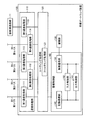
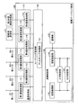
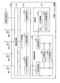
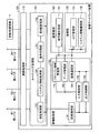
次に、本実施形態の車載ゲートウェイ装置100の詳細について説明する。図2は、車載ゲートウェイ装置100の機能的な構成例を示すブロック図である。本実施形態の車載ゲートウェイ装置100は、図2に示すように、通信処理部110と、ルーティング処理部120と、蓄積部130と、蓄積制御部140とを備える。
Next, the details of the in-
通信処理部110は、複数の内部通信処理部として、第1通信処理部111と、第2通信処理部112と、第3通信処理部113と、第4通信処理部114と、第5通信処理部115とを含む。第1通信処理部111は、第1バスB1に接続されたエンジン制御ECU12、ステアリング制御ECU13、ブレーキ制御ECU14、ライト制御ECU15およびエアバッグ制御ECU16と通信する処理を行う。第2通信処理部112は、第2バスB2に接続された空調制御ECU17、センサECU18および座席制御ECU19と通信する処理を行う。第3通信処理部113は、第3バスB3に接続された映像処理ECU20および第1外部通信処理部21と通信する処理を行う。第4通信処理部114は、第4バスB4に接続された運転支援制御ECU22および第2外部通信処理部23と通信する処理を行う。第5通信処理部115は、診断用通信部11と通信する処理を行う。
The
ルーティング処理部120は、通信処理部110に含まれるいずれかの通信処理部が入力したデータを他の通信処理部に転送し、バスを跨がる通信や診断用通信部11との間の通信を中継する処理を行う。すなわち、ルーティング処理部120は、どのバスから入力したデータをどのバスに出力するか、どのバスに接続されたどのECUから入力したデータをどのバスに出力するか、どのバスに接続されたどのECUから入力したデータをどのバスに接続されたどのECUに出力するかなどを決定する処理を行う。このとき、ルーティング処理部120は、バスの規格やプロトコル、データフォーマットが異なる場合は、プロトコル・フォーマットを変換する処理を行う。
The
ルーティング処理部120は、内部にフィルタリング処理部121を備える。フィルタリング処理部121は、設定されたポリシーに従って、ルーティング処理部120に入力されるデータの一部を蓄積制御部140に送信する処理を行う。
The
ルーティング処理部120は、上述のように、バスを跨がる通信を中継するため、バスを跨がってECU間で送受信されるデータはルーティング処理部120に入力される。また、バスを跨がない通信であっても、バス上にブロードキャストされたデータは通信処理部110によって受信されるため、ルーティング処理部120にそのデータを入力することができる。ここで、車載システム10を搭載する車両のイグニッションスイッチがオフか、走行中か、停車中か、外部装置と通信を行っているかといったように、車両の状態にも依存するが、車載システム10においては、多数のECUから制御コマンドや制御データが出力されるため、ルーティング処理部120が受信したり処理したりするデータも膨大な量になる。したがって、ルーティング処理部120が受信した全てのデータを蓄積部130に蓄積することは現実的ではない。そこで、フィルタリング処理部121は、設定されたポリシーに従って、必要なデータのみ蓄積制御部140に送信する。
Since the
なお、フィルタリング処理部121は、予め設定された固定のポリシーに従って蓄積制御部140に送信するデータを判定してもよいし、フィルタリング処理部121のポリシーを可変とし、蓄積制御部140に送信するデータをその都度判定してもよい。また、フィルタリング処理部121に設定するポリシーを、蓄積制御部140から更新できるように構成されていてもよい。
The
蓄積部130は、車載システム10に含まれる各ECUが出力するデータを蓄積する。この蓄積部130としては、例えばNANDフラッシュメモリやHDDなど、データを記録する媒体を用いることができる。
The
蓄積制御部140は、蓄積部130に蓄積するデータと蓄積部130から出力するデータとの少なくともいずれかを、所定のルールに従って加工または選別する処理を行う。
The
本実施形態では、車載システム10に含まれる各ECUが出力するデータが蓄積部130に蓄積される。この蓄積部130に蓄積されたデータの用途は多様である。例えば、車載システム10を搭載する車両に事故が発生した場合、オペレータ(車両の運転者)のミスによって発生した事故か、ソフトウェアの不具合によって発生した事故かを後から検証するための情報として利用することが考えられる。場合によっては、オペレータのミスによって発生した事故であることを車両の製造ベンダが証明するために、警察や裁判所などの公的機関にデータの提出が必要になる場合も想定される。また、オペレータが急加速や急発進といった事故につながりやすい操作をしていないかどうかをモニタリングし、燃費や安全運転に配慮した操作のアドバイスや保険額の割引など様々なサービスに利用することも考えられる。また、車両の製造ベンダが車載システム10の実試験を行い、改善に向けた評価を行うための情報として利用することも考えられる。
In the present embodiment, data output from each ECU included in the in-
また、車載システム10は様々な外部装置と通信することを想定している。したがって、様々な外部装置から攻撃を受ける可能性がある。一般的に、情報通信システムでは、設計者や実装者が意図していない不具合を悪用して攻撃がなされるが、すべての攻撃を事前に予測して、不具合を完全に排除した車載システム10を設計、実装することは困難である。車載システム10も不正な命令や不正なデータを排除する機能を備えていることが望ましいが、それらの対策を施していたとしても残念ながら攻撃が成立してしまう場合もある。このとき、仮に車載システム10の不具合により不正な命令や不正なデータを受け付けてしまったとしても、どのような情報が外部装置から送信されたのか記録できていれば、それを後から解析して不具合の修正に利用することができる。このため、ECUが出力するデータを車載システム10内に蓄積しておくことは、事後対応として有用である。
The in-
一般的に、車載システム10に含まれるECUは様々なものがあり、ECUやそこに搭載されるソフトウェアによって、車載システム10の品質や特性が変化する。このため、ECUが出力するデータには、オペレータにとって利用しやすい車載システム10を構成するためのノウハウが多々含まれている。したがって、車両の製造ベンダにとって、ECUが出力するデータを競争相手の製造ベンダに秘匿する必要がある。
In general, there are various types of ECUs included in the in-
また、ECUが出力するデータ群は上述のように様々な用途が考えられるため、例えば車両の製造ベンダや、警察、裁判所などの公的機関には蓄積部130に蓄積したデータをすべて公開し、保険会社には一部のデータを公開し、一般ユーザには最小限のデータを公開するといったように、データの開示範囲を制限する機能を備えておくことが望まれる。
In addition, since the data group output by the ECU can be used for various purposes as described above, for example, all data stored in the
また、車両の製造ベンダがデータを改変していないことを証明するか、車載ゲートウェイ装置100から出力した後にデータが何者かによって改変されることを防ぐ仕組みを備えている必要がある。
In addition, it is necessary to provide a mechanism for preventing data from being altered by someone after verifying that the manufacturer of the vehicle has not altered the data or outputting the data from the in-
本実施形態の車載ゲートウェイ装置100は、これらの要求を満足するために、蓄積部130へのデータの入力や蓄積部130からのデータの出力を制御する蓄積制御部140を備える。
In order to satisfy these requirements, the in-
蓄積制御部140は、記録通信部141と、入力制御部142と、出力制御部143と、蓄積通信部144と、を備える。記録通信部141は、ルーティング処理部120と通信する処理を行う。入力制御部142は、蓄積部130にデータを入力するときに加工・選別する処理を行う。出力制御部143は、蓄積部130からデータを出力するときに加工・選別する処理を行う。入力制御部142と出力制御部143の詳細は後述する。蓄積通信部144は、蓄積部130にデータを送信したり、蓄積部130からデータを受信したりする処理を行う。
The
なお、ルーティング処理部120から蓄積制御部140に送信されるデータは、上述したようにフィルタリング処理部121によって選別されたデータであるが、蓄積制御部140が、どのデータを送信するかをルーティング処理部120に指示する構成としてもよい。例えば、蓄積制御部140が蓄積部130の容量を監視し、一定以上の容量になった場合には蓄積部130でデータが溢れることを防ぐため、蓄積部130に記録するデータを制限するように、フィルタリング処理部121のポリシーの変更をルーティング処理部120に依頼してもよい。
The data transmitted from the
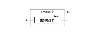
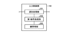
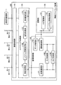
ここで、入力制御部142の具体例について説明する。図3−1乃至図3−3は、入力制御部142の内部構成例を示す図である。入力制御部142は、図3−1に示すように、内部に選別処理部201を備える構成と、図3−2に示すように、内部に第1暗号処理部202および鍵管理部203を備える構成と、図3−3に示すように、内部に選別処理部201、第1暗号処理部202および鍵管理部203を備える構成とがある。車載システム10に要求される性能や蓄積部130の容量サイズなどに応じて、最適な構成の入力制御部142を選択すればよい。
Here, a specific example of the
選別処理部201は、ルーティング処理部120から入力されたデータに対し、蓄積部130に蓄積するデータか否かを判定して、データの加工や選別を行う処理部である。選別処理部201は、予め設定された固定のルールに従って、ルーティング処理部120から入力されたデータが蓄積部130に蓄積するデータか否かを判定してもよいし、選別処理部201のルールを可変とし、ルーティング処理部120から入力されたデータが蓄積部130に蓄積するデータか否かを判定するルールが更新できるようになっていてもよい。
The
選別処理部201が用いるルールの例を以下に挙げる。
Examples of rules used by the sorting
ルール1−1:ルーティング処理部120から入力されたデータのビットレートに基づき、蓄積部130に蓄積するデータか否かを判定する。例えば、選別処理部201は、ルーティング処理部120から入力されたデータのビットレートを計測し、予め定めた上限を超える場合は、データを間引いて蓄積部130に入力するように制御する。
Rule 1-1: Based on the bit rate of the data input from the
ルール1−2:ルーティング処理部120から入力されたデータが、どのバスからのデータであるかによって、蓄積部130に蓄積するデータか否かを判定する。例えば、選別処理部201は、ルーティング処理部120から入力されたデータが第1バスB1からのデータであった場合は蓄積部130への入力を禁止するが、第2バスB2からのデータであった場合は蓄積部130への入力を許可するといったように、蓄積部130へのデータの入力を制御する。
Rule 1-2: It is determined whether or not the data input from the
ルール1−3:ルーティング処理部120から入力されたデータの種類に基づき、蓄積部130に蓄積するデータか否かを判定する。例えば、選別処理部201は、ルーティング処理部120から入力されたデータが動画データの場合は蓄積部130への入力を禁止するが、テキストデータ(数値データを含む)の場合は蓄積部130への入力を許可するといったように、蓄積部130へのデータの入力を制御する。他にも、例えば時間情報(時刻情報)は蓄積部130への入力を禁止するが、それ以外のデータは蓄積部130への入力を許可するといったように、データの種類に応じて蓄積部130へのデータの入力を制御する。
Rule 1-3: Based on the type of data input from the
ルール1−4:ルーティング処理部120から入力されたデータのサイズに基づき、蓄積部130に蓄積するデータか否かを判定する。例えば、選別処理部201は、ルーティング処理部120から入力されたデータのサイズがNキロバイト以上の場合は蓄積部130への入力を禁止するが、それより小さい場合は蓄積部130への入力を許可するといったように、蓄積部130へのデータの入力を制御する。
Rule 1-4: Based on the size of data input from the
ルール1−5:ルーティング処理部120から入力されたデータが、どのECUが出力したデータであるかによって、蓄積部130に蓄積するデータか否かを判定する。例えば、選別処理部201は、空調制御ECU17が出力したデータは蓄積部130への入力を許可するが、エンジン制御ECU12が出力したデータは蓄積部130への入力を禁止するといったように、蓄積部130へのデータの入力を制御する。
Rule 1-5: It is determined whether the data input from the
ルール1−6:センサECU18が物理的に異なる複数のECUを含み、これら複数のECUが同一のセンサ信号を取得して異なるバスに出力する場合、複数のECUが出力するデータが一致するか否かにより、蓄積部130に蓄積するデータか否かを判定する。例えば、センサ信号に冗長性を持たせるため、センサECU18に含まれる複数のECUを異なるバスに接続し、これら複数のECUが同一のセンサ信号を取得して、異なるバスに出力する構成とする場合がある。このような構成の場合、選別処理部201は、例えば、それら複数のECUが出力するデータが一致する間はいずれかのECUが出力するデータのみ蓄積部130に入力し、異なる場合はそれら複数のECUが出力するデータを蓄積部130に入力するといったように、蓄積部130へのデータの入力を制御する。これにより、故障あるいは不正アクセスによる問題の発生を検知することができ、原因追及に際して有用である。
Rule 1-6: When the sensor ECU 18 includes a plurality of physically different ECUs, and the plurality of ECUs acquire the same sensor signal and output it to different buses, whether or not the data output by the plurality of ECUs match. Therefore, it is determined whether or not the data is stored in the
ルール1−7:外部装置との間で認証が成功したか否かによって、ルーティング処理部120から入力されたデータを蓄積部130に蓄積するか否かを判定する。例えば、選別処理部201は、外部装置から第1外部通信処理部21、第2外部通信処理部23、あるいは診断用通信部11を経由して、予め設定したパスワード(PINコード)と一致する値が送信されてきた場合は、ルーティング処理部120から入力されたデータを蓄積部130に入力することを許可するが、予め設定したパスワード(PINコード)と一致する値が送信されない場合は、ルーティング処理部120から入力されたデータを蓄積部130に入力することを禁止するといったように、蓄積部130へのデータの入力を制御する。
Rule 1-7: Whether or not the data input from the
なお、選別処理部201は、外部装置との間で認証が成功した場合、ルーティング処理部120から入力された全てのデータが蓄積部130に入力されるように制御してもよいが、上記のルール1−1からルール1−6のいずれかまたはその組み合わせに従って、蓄積部130に入力するデータを選別してもよい。また、外部装置との間の認証方式は、パスワード認証に限らず、RSAなどの公開鍵アルゴリズムを用いた公開鍵認証でもよい。その場合、選別処理部201が秘密鍵を管理する。
Note that the
上記のルール1−7は、車載システム10を搭載する車両の製造ベンダがテスト用のデータを収集し、解析する際に極めて有用である。テスト用のデータは、オペレータや保険会社など、通常の利用時には蓄積する必要のない、あるいは取得されたくないデータであるが、製造ベンダにとっては有用なデータである。すなわち、車載システム10を再設計する際は、各種認定を再度取得するために実機でテストする場合がある。この場合、車載システム10の各ECUがテスト用のデータを出力するが、このとき製造ベンダのみが知り得るパスワードや鍵情報を元に認証を行うようにすれば、製造ベンダがテストを行う場合に限り、ECUが出力するテスト用のデータを蓄積部130に蓄積させることができる。
The above rules 1-7 are extremely useful when a manufacturing vendor of a vehicle equipped with the in-
ルール1−8:上記のルール1−1からルール1−7の任意の組み合わせ。 Rule 1-8: Any combination of the above rules 1-1 to 1-7.
なお、上記のルール1−1からルール1−8で検出した結果に応じて、ECUが出力するデータを蓄積部130に蓄積するか否かについて異なるポリシーを適用し、システム状況に応じたデータの蓄積(ログ蓄積)を行えるようになっていてもよい。例えば、ルール1−6の場合、より多くのログを採取したり、あるいは、故障時の冗長系からのログ採取に切り替えたりしてもよい。
Depending on the results detected in rules 1-1 to 1-8, a different policy is applied as to whether or not the data output from the ECU is stored in the
なお、入力制御部142は、ルーティング処理部120から入力されたデータを蓄積部130に入力する場合に、圧縮技術を用いて圧縮形式で蓄積部130に入力する構成としてもよい。例えば、同じデータの値が連続して同じ値だった場合に、同じデータを連続回数分送るのではなく圧縮して送る。
The
また、入力制御部142は、ルーティング処理部120から入力されたデータを蓄積部130に入力する場合に、そのデータに統計処理を施してもよい。例えば、同じECUからの同種のデータが時間X、Y、Zでルーティング処理部120から入力された場合、3つのデータを蓄積部130に入力するのではなく、それら3つのデータの平均値を蓄積部130に入力してもよい。
Further, when the data input from the
また、入力制御部142は、ルーティング処理部120から入力されたデータを蓄積部130に入力する場合に、そのデータに車載システム10を搭載した車両のオペレータを識別する情報を付与してもよい。オペレータの癖などによって、車両の操作方法が異なる可能性がある。蓄積部130に蓄積されたデータを解析する際、どのオペレータが操作したときにECUが出力したデータであるか区別できれば、燃費や安全運転に配慮した操作のアドバイスや保険額の割引など様々なサービスに利用することができる。オペレータを区別する方法としては、例えば、車内カメラで人物認識する方法、指紋や声紋などの生体情報で識別する、あるいは、運転免許証やクレジットカードなどオペレータを特定する所有物を読み込むリーダで認識する方法などがある。それらカメラやセンサ、カードリーダなどの各種リーダが読み込んだ情報を入力制御部142に伝える。
Further, when the data input from the
なお、上記のルール1−2やルール1−5に従った判定は、ルーティング処理部120のフィルタリング処理部121でも行う場合がある。上述のようにバスの規格によってはデータがブロードキャストされる場合がある。そのようなバスの規格では、送り主アドレスと送り先アドレスをフィルタリング処理部121で判定できない場合がある。このような場合に備え、本実施形態では、類似の処理をフィルタリング処理部121でも入力制御部142でも行う構成になっている。
Note that the determination according to the rules 1-2 and 1-5 may be performed by the
また、以上の例では、蓄積部130に蓄積するデータの選別を選別処理部201が行う構成であるが、データの選別処理はフィルタリング処理部121で行う構成としてもよい。すなわち、選別処理部201は、上記のルール1−1からルール1−8のいずれかを保持し、そのルールに従ってフィルタリング処理部121のポリシーを設定し、選別処理部201が保持するルールに従ってフィルタリング処理部121が選別処理を行う構成としてもよい。
In the above example, the
第1暗号処理部202は、ルーティング処理部120から入力されたデータに暗号処理を施す。鍵管理部203は、第1暗号処理部202が暗号処理に使用する鍵を管理する。なお、暗号アルゴリズムは、AESのような共通鍵暗号でもよいし、RSAや楕円曲線暗号のような公開鍵暗号でもよい。入力制御部142が第1暗号処理部202と鍵管理部203を備える図3−2の構成の場合、蓄積部130には、暗号化されたデータが蓄積される。したがって、例えば攻撃者が蓄積部130のみを取り外してデータを取得したとしても、攻撃者は平文のデータを取得することはできない。
The first
なお、暗号処理はデータの秘匿化に限らず、メッセージ認証コード(MAC:Message Authentication Code)などによる完全性を保証する処理であってもよい。この場合、第1暗号処理部202は、例えばHMACなどのアルゴリズムを用い、データにMAC値を付けて蓄積部130に入力する。さらに、暗号処理は署名を付与する処理であってもよい。この場合、第1暗号処理部202は、例えばRSAのような公開鍵暗号を用いてデータに対する署名値を生成し、データに署名値を付けて蓄積部130に蓄積する。もちろんデータサイズが大きい場合は、例えばSHA−1などのハッシュアルゴリズムを用いてハッシュ値を計算し、そのハッシュ値に対する署名値を計算してもよい。
The encryption process is not limited to data concealment, and may be a process for guaranteeing integrity by a message authentication code (MAC). In this case, the first
図3−3に示すように、内部に選別処理部201、第1暗号処理部202および鍵管理部203を備える構成の入力制御部142では、第1暗号処理部202がどのデータを暗号化するかが選別処理部201により選定される。この場合、ルーティング処理部120から入力されたデータは、選別処理部201によって、蓄積部130に蓄積しないか、第1暗号処理部202により暗号処理を施して蓄積部130に蓄積するか、平文のまま蓄積部130に蓄積するか判定される。選別処理部201による判定処理は、例えば、上述したルール1−1からルール1−8のいずれかに従って行うことができる。
As shown in FIG. 3C, in the
なお、蓄積部130に蓄積するデータに対して第1暗号処理部202が暗号処理を行う場合は、データの出力先に応じて異なる鍵を用いた暗号処理を行うようにしてもよい。すなわち、暗号処理に用いる鍵を分けることによって、例えば、製造ベンダと公的機関のみが全てのデータを復号でき、保険会社は特定のデータのみを復号できるといったように、アクセス可能な対象者を区別するようにしてもよい。同様に、データの出力先に応じて異なる暗号アルゴリズムを用いた暗号処理を行うようにしてもよい。
When the first
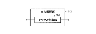
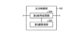
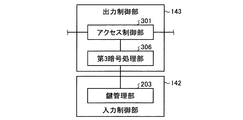
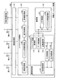
次に、出力制御部143の具体例について説明する。図4−1乃至図4−6は、出力制御部143の内部構成例を示す図である。出力制御部143は、図4−1に示すように、内部にアクセス制御部301を備える構成と、図4−2に示すように、内部にアクセス制御部301、モード設定部302および認証処理部303を備える構成と、図4−3に示すように、内部に第2暗号処理部304および第2鍵管理部305を備える構成と、図4−4に示すように、内部にアクセス制御部301、第3暗号処理部306および第3鍵管理部307を備える構成と、図4−5に示すように、内部にアクセス制御部301および第3暗号処理部306を備える構成と、図4−6に示すように、内部にアクセス制御部301、第2暗号処理部304および第2鍵管理部305を備える構成とがある。車載システム10に要求される性能やセキュリティレベルなどに応じて、最適な構成の出力制御部143を選択すればよい。
Next, a specific example of the
アクセス制御部301は、蓄積部130からの出力が要求されたデータに対し、出力できるデータか否かを判定して、出力するデータの加工や選別を行う処理部である。アクセス制御部301は、予め設定された固定のルールに従って、出力が要求されたデータが出力できるデータか否かを判定してもよいし、アクセス制御部301のルールを可変とし、出力が要求されたデータが出力できるデータか否かを判定するルールが更新できるようになっていてもよい。
The access control unit 301 is a processing unit that determines whether the data requested to be output from the
アクセス制御部301が用いるルールの例を以下に挙げる。 Examples of rules used by the access control unit 301 are given below.
ルール2−1:出力が要求されたデータをルーティング処理部120に送信する際のビットレートに基づき、出力できるデータか否かを判定する。例えば、アクセス制御部301は、出力が要求されたデータのビットレートを計測し、予め定めた上限を超える場合は、データを間引いてルーティング処理部120に送信するように制御する。
Rule 2-1: Based on the bit rate when the data requested to be output is transmitted to the
ルール2−2:出力が要求されたデータの出力先に応じて、出力できるデータか否かを判定する。例えば、アクセス制御部301は、出力が要求されたデータが診断用通信部11から外部機器に送信される場合は出力を禁止するが、第2外部通信処理部23から外部機器に送信される場合は出力を許可するといったように、蓄積部130に蓄積されたデータの出力を制御する。
Rule 2-2: It is determined whether or not the data can be output according to the output destination of the data requested to be output. For example, the access control unit 301 prohibits output when data requested to be output is transmitted from the diagnostic communication unit 11 to the external device, but transmits data from the second external
ルール2−3:出力が要求されたデータの種類に基づき、出力できるデータか否かを判定する。例えば、アクセス制御部301は、出力が要求されたデータが動画データの場合は出力を禁止するが、テキストデータ(数値データを含む)の場合は出力を許可するといったように、蓄積部130に蓄積されたデータの出力を制御する。他にも、例えば時間情報(時刻情報)は出力を禁止するが、それ以外のデータは出力を許可するといったように、データの種類に応じて蓄積部130に蓄積されたデータの出力を制御する。
Rule 2-3: Based on the type of data requested to be output, it is determined whether the data can be output. For example, the access control unit 301 stores data in the
ルール2−4:出力が要求されたデータのサイズに基づき、出力できるデータか否かを判定する。例えば、アクセス制御部301は、出力が要求されたデータのサイズがNキロバイト以上の場合は出力を禁止するが、それより小さい場合は出力を許可するといったように、蓄積部130に蓄積されたデータの出力を制御する。 Rule 2-4: It is determined whether or not the data can be output based on the size of the data requested to be output. For example, the access control unit 301 prohibits the output when the size of the data requested to be output is N kilobytes or more, but permits the output when the size is smaller than that. Control the output of.
ルール2−5:出力が要求されたデータが、どのECUが出力したデータであるかによって、出力できるデータか否かを判定する。例えば、アクセス制御部301は、出力が要求されたデータが空調制御ECU17が出力したデータであれば出力を許可するが、エンジン制御ECU12が出力したデータであれば出力を禁止するといったように、蓄積部130に蓄積されたデータの出力を制御する。なお、この場合、データを蓄積部130に蓄積する際に、入力制御部142がどのECUから入力したデータであるかを示す情報を付与して蓄積するようにしてもよい。
Rule 2-5: It is determined whether or not the data requested to be output is data that can be output depending on which ECU has output the data. For example, the access control unit 301 allows the output if the data requested to be output is the data output by the air conditioning control ECU 17, but prohibits the output if the data is output by the
ルール2−6:センサECU18が物理的に異なる複数のECUを含み、これら複数のECUが同一のセンサ信号を取得して異なるバスに出力する構成において、複数のECUが同一のセンサ信号を取得して出力したデータが蓄積部130に蓄積されている場合、これら複数のECUが出力したデータが一致するか否かにより、出力できるデータか否かを判定する。例えば、アクセス制御部301は、複数のECUが出力したデータが異なる場合は攻撃やエラーの解析のため出力を許可し、一致する場合は出力を禁止するといったように、蓄積部130に蓄積されたデータの出力を制御する。なお、この場合、データを蓄積部130に蓄積する際に、入力制御部142が同一のセンサから入力したデータであることを示す情報を付与して蓄積するようにしてもよい。
Rule 2-6: In a configuration in which the sensor ECU 18 includes a plurality of physically different ECUs, and the plurality of ECUs acquire the same sensor signal and output it to different buses, the plurality of ECUs acquire the same sensor signal. If the data output in this manner is stored in the
ルール2−7:外部装置との間で認証が成功したか否かによって、出力が要求されたデータを出力するか否かを判定する。例えば、アクセス制御部301は、外部装置から第1外部通信処理部21、第2外部通信処理部23、あるいは診断用通信部11を経由して、予め設定したパスワード(PINコード)と一致する値が送信されてきた場合は、出力が要求されたデータの出力を許可するが、予め設定したパスワード(PINコード)と一致する値が送信されない場合は、出力が要求されたデータの出力を禁止するといったように、蓄積部130に蓄積されたデータの出力を制御する。
Rule 2-7: It is determined whether or not the data requested to be output is output depending on whether or not the authentication with the external device is successful. For example, the access control unit 301 uses the first external communication processing unit 21, the second external
なお、アクセス制御部301は、外部装置との間で認証が成功した場合、出力が要求された全てのデータの出力を許可してもよいが、上記のルール2−1からルール2−6のいずれかまたは組み合わせに従って、出力を許可するデータを選別してもよい。また、外部装置との間の認証方式は、パスワード認証に限らず、RSAなどの公開鍵アルゴリズムを用いた公開鍵認証でもよい。その場合、アクセス制御部301が秘密鍵を管理する。 Note that the access control unit 301 may permit the output of all the data requested to be output when the authentication with the external device is successful, but the rules 2-1 to 2-6 above may be permitted. Data that is permitted to be output may be selected according to any one or combination. The authentication method with the external device is not limited to password authentication, but may be public key authentication using a public key algorithm such as RSA. In that case, the access control unit 301 manages the secret key.
ルール2−8:上記のルール2−1からルール2−7の任意の組み合わせ。 Rule 2-8: Any combination of the above rules 2-1 to 2-7.
なお、出力制御部143は、蓄積部130に蓄積されたデータが圧縮技術によって圧縮されている場合、そのデータに対して伸長処理を施す。
When the data stored in the
また、出力制御部143は、蓄積部130に蓄積されたデータに対して統計処理を施して出力してもよい。例えば、同じECUからの同種のデータが時間X、Y、Zで蓄積部130に記録されている場合、3つのデータを出力するのではなく、それら3つのデータの平均値を出力してもよい。
Further, the
モード設定部302は、アクセス制御部301の動作を有効にするか無効にするか設定する処理を行う。モード設定部302によりアクセス制御部301が有効に設定されていれば、アクセス制御部301によって上記のルール2−1からルール2−8のいずれかに従ったデータの選別や加工が行われる。一方、アクセス制御部301が無効に設定されている場合は、出力が要求されたデータが蓄積部130からそのまま出力される。
The
認証処理部303は、モード設定部302の動作を制限するための認証処理を行う。すなわち、認証処理部303が認証成功としたときのみ、モード設定部302がアクセス制御部301を有効にしたり無効にしたり設定できる。これにより、パスワードや秘密鍵の値を知らない攻撃者によって不正にアクセス制御部301の設定が変更されることを防止できる。認証の方式としては、例えば、認証処理部303に予め設定されたパスワード(PINコード)を用いる方法(パスワード認証)、RSAや楕円曲線暗号などの公開鍵アルゴリズムを用いて公開鍵認証を用いる方法などがある。
The
なお、モード設定部302は、アクセス制御部301の動作を有効にするか無効にするかの設定だけでなく、アクセス制御部301が用いるルールを変更する設定を行ってもよい。例えば、アクセス制御部301にルール2−1が適用されている場合、認証処理部303による認証が成功すると、モード設定部302は、アクセス制御部301にルール2−2を適用するように設定する構成としてもよい。
Note that the
第2暗号処理部304は、蓄積部130からの出力が要求されたデータに暗号処理を施す。第2鍵管理部305は、第2暗号処理部304が暗号処理に使用する鍵を管理する。なお、暗号アルゴリズムは、AESのような共通鍵暗号でもよいし、RSAや楕円曲線暗号のような公開鍵暗号でもよい。出力制御部143が第2暗号処理部304と第2鍵管理部305を備える図4−3の構成の場合、蓄積部130から出力されるデータは暗号化される。そして、共通鍵の場合は第2鍵管理部305が管理する鍵と同じ値を、公開鍵の場合は第2鍵管理部305の公開鍵に対応する秘密鍵の値を持っている場合に限り、蓄積部130から出力されたデータを平文に復号することができる。したがって、鍵の値を知らない攻撃者は暗号化されたデータを復号することができないため、蓄積部130のデータが平文で攻撃者に取得されることを防止できる。
The second
なお、暗号処理はデータの秘匿化に限らず、メッセージ認証コード(MAC)などによる完全性を保証する処理であってもよい。この場合、第2暗号処理部304は、例えばHMACなどのアルゴリズムを用い、蓄積部130から出力されるデータにMAC値を付ける。さらに、暗号処理は署名を付与する処理であってもよい。この場合、第2暗号処理部304は、例えばRSAのような公開鍵暗号を用いてデータに対する署名値を生成し、蓄積部130から出力されるデータに署名値を付ける。もちろんデータサイズが大きい場合は、例えばSHA−1などのハッシュアルゴリズムを用いてハッシュ値を計算し、そのハッシュ値に対する署名値を計算してもよい。
The encryption process is not limited to data concealment, and may be a process for guaranteeing integrity by a message authentication code (MAC) or the like. In this case, the second
図4−6に示すように、内部にアクセス制御部301、第2暗号処理部304および第2鍵管理部305を備える構成の出力制御部143では、蓄積部130に平文で蓄積されているデータのうち、第2暗号処理部304がどのデータを暗号化するかがアクセス制御部301により選定される。この場合、蓄積部130から出力されるデータは、アクセス制御部301によって、第2暗号処理部304により暗号処理を施して出力するか、平文のまま出力するかが判定される。アクセス制御部301による判定処理は、例えば、上述したルール2−1からルール2−8のいずれかに従って行うことができる。
As shown in FIG. 4-6, in the
なお、蓄積部130から出力するデータに対して第2暗号処理部304が暗号処理を行う場合は、データの出力先に応じて異なる鍵を用いた暗号処理を行うようにしてもよい。すなわち、暗号処理に用いる鍵を分けることによって、例えば、製造ベンダと公的機関のみが全てのデータを復号でき、保険会社は特定のデータのみを復号できるといったように、アクセス可能な対象者を区別するようにしてもよい。
When the second
第3暗号処理部306は、蓄積部130に蓄積されたデータが入力制御部142の第1暗号処理部202により暗号化されている場合に、蓄積部130から出力するデータに対して復号処理を施す。第3鍵管理部307は、第3暗号処理部306が使用する鍵を管理する。第1暗号処理部202で暗号化されたデータが蓄積部130に蓄積されている場合、蓄積部130に蓄積されているデータのうち、どのデータを第3暗号処理部306で復号するかがアクセス制御部301により選定される。すなわち、蓄積部130から出力されるデータは、アクセス制御部301によって、第3暗号処理部306により復号して平文として出力するか、暗号文のまま出力するかが判定される。アクセス制御部301による判定処理は、例えば、上述したルール2−1からルール2−8のいずれかに従って行うことができる。
The third
なお、共通鍵暗号が用いられている場合は、入力制御部142の鍵管理部203に格納された値と同じ値を第3鍵管理部307に格納してもよいし、図4−5に示す構成のように、出力制御部143内部に第3鍵管理部307を設けずに、第3暗号処理部306が入力制御部142の鍵管理部203から鍵を取得してもよい。
When common key cryptography is used, the same value as the value stored in the
蓄積部130に蓄積されたデータの出力を要求する方法としては、車載システム10に含まれるECUが出力要求メッセージを送信する方法、外部装置が診断用通信部11、第1外部通信処理部21、第2外部通信処理部23のいずれかを介して出力要求メッセージを送信する方法などがある。また、蓄積部130に蓄積されたデータの出力先としては、内部のバスを経由してECUに出力する、診断用通信部11、第1外部通信処理部21、第2外部通信処理部23のいずれかを介して外部装置に出力するなどがある。外部装置へ出力する場合は有線の場合もあるし、無線の場合もある。蓄積部130に蓄積されたデータの出力を要求する出力要求メッセージに、出力先を指定する情報を付与してもよいし、車載ゲートウェイ装置100に予め出力先が指定されていてもよい。出力先を指定する情報として、バスを指定する方法、ECUを指定する方法、診断用通信部11を指定する方法などがある。
As a method of requesting output of data stored in the
なお、いずれの認証または暗号化を施す場合も、どのバスまたはどのECUからの要求であるかをアクセス制御部301が判定する処理を行い、バスまたはECUによってアクセス制御部301の動作を変更できるようになっていてもよい。例えば、ルーティング処理部120を介して第1バスB1からアクセス制御部301の動作を変更する場合にはモード設定部302は無効になり、アクセス制御部301の動作を有効にしたり無効にしたり設定できるが、診断用通信部11からアクセス制御部301の動作を変更する場合にはモード設定部302が有効となり、認証処理部303との認証が成功しない限りアクセス制御部301の設定を変更できないといった構成になっていてもよい。同様に、ルーティング処理部120を介して第1バスB1から蓄積部130に蓄積されたデータの出力が要求された場合にはデータは平文のまま出力されるが、診断用通信部11から蓄積部130に蓄積されたデータの出力が要求された場合には、データは第2暗号処理部304によって暗号化されて出力されるといった構成になっていてもよい。
In any of the authentications or encryptions, the access control unit 301 performs a process for determining which bus or which request is sent from the ECU so that the operation of the access control unit 301 can be changed by the bus or the ECU. It may be. For example, when the operation of the access control unit 301 is changed from the first bus B1 via the
なお、以上の例では、蓄積部130にデータを入力するときに入力制御部142がデータの加工・選別を行うとともに、蓄積部130からデータを出力するときに出力制御部143がデータの加工・選別を行うようにしているが、データの加工・選別は、蓄積部130にデータを入力するとき、あるいは、蓄積部130からデータを出力するときのいずれかのみ行う構成としてもよい。
In the above example, the
以上、具体的な例を挙げながら詳細に説明したように、本実施形態の車載ゲートウェイ装置100は、ECUが出力するデータを蓄積部130に蓄積し、蓄積部130に蓄積したデータを出力する際に、所定のルールに従ってデータを加工または選別するようにしている。したがって、この車載ゲートウェイ装置100によれば、蓄積部130に蓄積するデータを保護しながら、データの用途に応じてその出力を制限することができる。これにより、蓄積部130に蓄積するデータが悪意の第3者に取得されたり、蓄積部130に蓄積するデータを不用意に開示してしまったりする不都合を有効に抑制することができる。
As described above in detail with specific examples, the in-
また、本実施形態によれば、蓄積部130に蓄積するデータを加工または選別することにより、蓄積部130のデータあふれを抑制することができるとともに、蓄積部130のバス幅を小さくすることができるため、蓄積部130のコストを削減することができる。
In addition, according to the present embodiment, by processing or selecting data stored in the
なお、図1に示した車載システム10の構成では、映像処理ECU20と運転支援制御ECU22が外部と通信するために、それぞれ別々の通信処理部(第1外部通信処理部21および第2外部通信処理部23)と接続されている。しかし、外部と通信するための通信処理部をひとつにまとめた構成としてもよい。その場合の車載システム10の構成例を図5に示す。
In the configuration of the in-
図5に示す車載システム10は、図1の第1外部通信処理部21と第2外部通信処理部23との代わりに、車載ゲートウェイ装置100に接続された第3外部通信処理部24を備えている。第3外部通信処理部24は、例えば、3GPP(登録商標)やLTE(登録商標)などの移動体通信網や、Wi−Fi(登録商標)、Bluetooth(登録商標)、802.11pなどの無線を用いて、インターネット、路側機や他の外部装置と通信する処理を行う。
The in-
図1に示した構成の車載システム10では、映像処理ECU20は車載ゲートウェイ装置100を介さず直接、第1外部通信処理部21を用いて外部と通信していた。同様に、運転支援制御ECU22も車載ゲートウェイ装置100を介さず直接、第2外部通信処理部23を用いて外部と通信していた。しかし、図5に示す構成の車載システム10では、映像処理ECU20や運転支援制御ECU22は、第3外部通信処理部24を用いて外部と通信するために車載ゲートウェイ装置100を介す必要がある。その場合の車載ゲートウェイ装置100の構成例を図6に示す。
In the in-
図6に示す車載ゲートウェイ装置100は、図2に示す構成と比較して、通信処理部110に第6通信処理部116が追加で含まれている点のみが異なる。第6通信処理部116は、第3外部通信処理部24と通信する処理を行う。映像処理ECU20が第3外部通信処理部24を用いて外部と通信する場合は、映像処理ECU20と第3外部通信処理部24は、第3通信処理部113、ルーティング処理部120および第6通信処理部116を介して接続される。また、運転支援制御ECU22が第3外部通信処理部24を用いて外部と通信する場合は、運転支援制御ECU22と第3外部通信処理部24は、第4通信処理部114、ルーティング処理部120および第6通信処理部116を介して接続される。
The in-
また、図2に示した車載ゲートウェイ装置100の構成では、ルーティング処理部120と蓄積制御部140はそれぞれ個別に設けられている。しかし、ルーティング処理部120内に蓄積制御部140を組み込んだ構成とすることも可能である。その場合の車載ゲートウェイ装置100の構成例を図7に示す。
In the configuration of the in-
図7に示す車載ゲートウェイ装置100では、蓄積制御部140がルーティング処理部120内に組み込まれている。このため、蓄積制御部140に記録通信部141は設けられていない。
In the in-
図2に示した構成の車載ゲートウェイ装置100では、ルーティング処理部120が、設定されたポリシーに従って必要なデータのみ蓄積制御部140に送信する処理を行っていた。これに対し、図7に示す構成の車載ゲートウェイ装置100では、蓄積制御部140の入力制御部142がこの処理を行う。すなわち、入力制御部142は、ルーティング処理部120に設定されたポリシーに従ってルーティング処理部120に入力されたデータの選別を行うとともに、上述したルール1−1からルール1−8のいずれかに従って、蓄積部130に蓄積するデータの加工・選別を行う。
In the in-
また、図2に示した構成の車載ゲートウェイ装置100では、蓄積部130から出力するデータを出力制御部143が加工・選別し、記録通信部141からルーティング処理部120に送信していた。これに対し、図7に示す構成の車載ゲートウェイ装置100では、蓄積制御部140がルーティング処理部120に組み込まれているため、出力制御部143は、加工・選別したデータを直接ルーティング処理部120に受け渡す処理を行う。ルーティング処理部120は、そのデータを第1バスB1、第2バスB2、第3バスB3、第4バスB4、または診断用通信部11に転送する処理を行う。
In the in-
<第2実施形態>
次に、第2実施形態について説明する。第1実施形態では、車載システム10に含まれるECUが出力するデータを蓄積部130に格納していた。これに対し第2実施形態では、ECUから出力されたデータに加え、ECUのファームウェアに関する情報をシステム情報として蓄積する点が、第1実施形態と異なる。以下、第1実施形態との相違点についてのみ説明する。
Second Embodiment
Next, a second embodiment will be described. In the first embodiment, data output by the ECU included in the in-
一般的に、車載システム10には数多くの様々な種類のECUが搭載されている。図1では、それら多数のECUの一例としてエンジン制御ECU12などを例示したが、これら以外にも様々なECUが搭載されている。車載システム10は、複数の異なるベンダが提供するECUを搭載していることが一般的である。それらのECUの中には、ハードウェアのみで実現されているものと、ハードウェアとソフトウェア(ファームウェア)で構成されているものがある。ハードウェアとファームウェアで構成されているもののうち、ファームウェアが工場出荷時に組み込まれ、工場出荷後に更新(アップデート)することができないようになっているものもあるが、ファームウェアをECU単体で工場から出荷後、あるいは車載システム10としてアセンブルされた後に、機能追加、性能向上、不具合の改善などを目的として、後から新しいファームウェアにアップデートする機能を備えているものもある。
In general, the in-
このとき課題となるのが、ファームウェアの更新である。パーソナルコンピュータ(PC)を中心としたITシステムの場合、各PCが常時インターネットに接続されている場合が多いため、各PCは最新のファームウェアがサーバ上で配布されているか定期的に確認し、ファームウェアが提供されたと同時に更新することが可能である。 The issue at this time is updating the firmware. In the case of IT systems centered on personal computers (PCs), each PC is often connected to the Internet at all times, so each PC periodically checks whether the latest firmware is distributed on the server, and firmware Can be updated at the same time.
しかし、車載システム10はファームウェアを配布するサーバとネットワークで常時接続されているわけではない。例えば、車載システム10を搭載した車両がトンネルや地下道路を走行中の場合、外部装置と通信できない場合もあるし、車両を週末のみ利用する(イグニッションをオンにする)といったこともあり得る。したがって、必ずしもすべての車載システム10がすべてのECUに対して最新のファームウェアを取得し、インストールしているとは限らない。また、ECUの故障により、同一種類の車載システム10であってもあるECUは最新のファームウェアがインストールされているが、別のECUは古いファームウェアがインストールされているという状況もあり得る。
However, the in-
さらに、上述のようにECUを提供するベンダは異なり、各ECUの機能はそれぞれ異なるため、ECUごとに個別にアップデートされていくことが見込まれる。したがって、仮に同じベンダが提供する同じ種類の車載システム10だとしても、ECUのファームウェアのバージョンの組み合わせは相当な数にのぼる。例えば、あるECUのバージョンがXであり、別のECUのバージョンがYの場合にのみ不具合が発生するといったように、特定のファームウェアのバージョンの組み合わせで不具合が発生する場合も考えらえる。
Further, as described above, vendors that provide ECUs are different, and the functions of each ECU are different from each other. Therefore, it is expected that each ECU will be updated individually. Therefore, even if the same type of in-
また、セキュリティの観点からは、車載システム10のシステム構成によって攻撃の成否が異なり、特定のファームウェアの組み合わせで特定の攻撃が成立する場合もある。このように、車載システム10のシステム構成は、不具合や攻撃などの問題解決を進める上で、重要な手掛かりとなり得る。仮に事故が発生した場合、どのような不具合で生じたのかどうかを車両の製造ベンダが確認したり解析したりする作業が必要になるが、ファームウェアの組み合わせが分からなければ究明に多大なコストがかかる。
Further, from the viewpoint of security, the success or failure of the attack differs depending on the system configuration of the in-
以上のことから、車両の製造ベンダが、ECUが出力したデータとともに各ECUのファームウェアの状態を把握することができれば、再現も容易になるため、原因を究明するための解析が容易になると考えらえる。さらに、外部から有効な攻撃が発生しているか否かを車両の製造ベンダが事後的に効率よく解析するために、車載システム10内にシステム構成に関する情報を蓄積しておく必要があるが、蓄積すべきデータの種類・管理方法、出力方法が明らかになっていない。
From the above, if the vehicle manufacturer can grasp the status of the firmware of each ECU together with the data output from the ECU, it will be easy to reproduce, and therefore it will be easy to analyze the cause. Yeah. Furthermore, in order for the vehicle manufacturing vendor to efficiently analyze whether or not an effective attack has occurred from the outside, it is necessary to store information on the system configuration in the in-
本実施形態では、車載ゲートウェイ装置100が、ECUが出力するデータに加えて、ECUのファームウェアに関する情報をシステム情報として蓄積し、データの解析を行う場合に各ECUのファームウェアの状態を把握できるようにすることで、データの解析を容易かつ効率よく行えるようにする。
In the present embodiment, in-
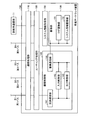
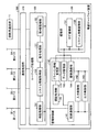
図8は、本実施形態の車載ゲートウェイ装置100の機能的な構成例を示すブロック図である。図2に示した第1実施形態の構成と比較して、システム情報取得部150が追加されている点と、蓄積部130がログ蓄積部131とシステム情報蓄積部132とを備える点が異なる。
FIG. 8 is a block diagram illustrating a functional configuration example of the in-
システム情報取得部150は、車載システム10に含まれる各ECUのファームウェアに関する情報を取得する処理を行う。ECUのファームウェアに関する情報とは、ファームウェアのバージョン情報であってもよいし、ファームウェアのハッシュ値であってもよい。また、ECUのファームウェアに関する情報は、日付などのファームウェアのメタデータ、ファームウェアのサイズ、ファームウェアに添付されている署名、ファームウェアを提供するベンダに関する情報などを含んでいてもよい。また、ファームウェアに関する情報は、動作中のRAMイメージに関する情報であってもよい。
The system
システム情報取得部150は、取得したECUのファームウェアに関する情報を、蓄積部130に送信する。システム情報取得部150がECUのファームウェアに関する情報を取得するタイミングとしては、各ECUから定期的に取得する方法、車両のイグニッションがオンしたときに取得する方法、外部装置からの指示に応じて取得する方法、ECUの故障など異常を検出したときに取得する方法、特定のECUからの指示に応じて収集する方法などがある。特定のECUからの指示とは、例えば、エアバッグ制御ECU16が車載システム10の衝突などのイベントを検出したときにシステム情報取得部150に指示を送信する場合などを指す。また、ECUのファームウェアに関する情報が更新された場合には、更新前のファームウェアに関する情報を上書きしてもよいし、更新前の情報を消さずに履歴として残しておき、追記してもよい。
The system
本実施形態の車載ゲートウェイ装置100では、蓄積部130が、ログ蓄積部131とシステム情報蓄積部132とから構成される。ログ蓄積部131は、第1実施形態における蓄積部130と同一の機能を持つ。すなわち、ログ蓄積部131は、ECUが出力するデータであって、蓄積制御部140の入力制御部142により加工・選別されたデータを蓄積する。一方、システム情報蓄積部132は、システム情報取得部150が取得したECUのファームウェアに関する情報をシステム情報として蓄積する。
In the in-
第1の実施形態では、ECUが出力するデータを入力制御部142により加工・選別して蓄積部130に蓄積する仕組みを説明したが、ECUのファームウェアに関する情報についても同様に、加工・選別してシステム情報蓄積部132に蓄積する構成としてもよい。例えば、入力制御部142の選別処理部201が、システム情報取得部150が取得したECUのファームウェアに関する情報について、どのバスに出力するか、どのバスから入力されたか、どのECUから取得されたかなどによって、システム情報蓄積部132に蓄積すべきか否かを判定し、蓄積すべきと判定したもののみ蓄積するようにしてもよい。また、この判定は、ECUが出力するデータと独立に行ってもよい。すなわち、あるECUが出力するデータはログ蓄積部131に蓄積することを禁止するが、そのECUのファームウェアに関する情報はシステム情報蓄積部132に蓄積することを許可するといった判定を行ってもよい。
In the first embodiment, the mechanism in which the data output from the ECU is processed / selected by the
同様に、あるECUが出力するデータを第1暗号処理部202により暗号化するか否かと、そのECUのファームウェアに関する情報を第1暗号処理部202により暗号化するか否かを別々に決めてもよい。また、双方を暗号化する場合は別々の鍵で暗号化するように、複数の鍵を鍵管理部203が管理するように構成してもよい。
Similarly, whether or not the data output by an ECU is encrypted by the first
また、第1の実施形態では、蓄積部130から出力するデータを出力制御部143により加工・選別する仕組みを説明したが、ECUのファームウェアに関する情報についても同様に、システム情報蓄積部132から出力するデータを加工・選別する構成としてもよい。例えば、出力制御部143のアクセス制御部301が、システム情報蓄積部132からの出力が要求されたファームウェアに関する情報について、どのバスに出力するか、どのバスから入力されたか、どのECUから取得されたかなどによって、出力を許可するか否かを判定し、出力を許可すると判定したもののみ出力するようにしてもよい。また、この判定は、ECUが出力するデータと独立に行ってもよい。すなわち、あるECUが出力するデータはログ蓄積部131から出力することを禁止するが、そのECUのファームウェアに関する情報はシステム情報蓄積部132から出力することを許可するといった判定を行ってもよい。
In the first embodiment, the mechanism for processing / selecting the data output from the
同様に、あるECUが出力するデータと、そのECUのファームウェアに関する情報について、第2暗号処理部304により暗号化するか否か、第3暗号処理部306により復号するか否かなども別々に決めてもよい。また、双方を暗号化、復号する場合は別々の鍵で暗号化するように、複数の鍵を第2鍵管理部305や第3鍵管理部307が管理するように構成してもよい。さらに、モード設定部302の設定についても、あるECUが出力するデータと、そのECUのファームウェアに関する情報とで別々に行ってもよい。
Similarly, whether the data output from an ECU and the information related to the firmware of the ECU are encrypted by the second
以上のように、本実施形態の車載ゲートウェイ装置100は、ECUが出力するデータをログ蓄積部131に蓄積するとともに、ECUのファームウェアに関する情報をシステム情報蓄積部132に蓄積する。したがって、例えば車両の製造ベンダがECUが出力したデータを解析する際に、ECUのファームウェアに関する情報も取得して解析を行うことができ、データの解析を容易かつ効率よく行うことができる。
As described above, the in-
なお、図8に示した車載ゲートウェイ装置100の構成では、システム情報取得部150がルーティング処理部120と接続されていたが、システム情報取得部150を蓄積制御部140内に組み込んだ構成としてもよい。その場合の車載ゲートウェイ装置100の構成例を図9に示す。
In the configuration of the in-
図9に示す車載ゲートウェイ装置100では、システム情報取得部150が蓄積制御部140内に組み込まれている。この構成の場合、システム情報取得部150が取得したECUのファームウェアに関する情報は、記録通信部141、入力制御部142、蓄積通信部144を介して蓄積部130に送信され、システム情報蓄積部132に蓄積される。
In the in-
また、システム情報取得部150をルーティング処理部120内に組み込んだ構成とすることも可能である。その場合の車載ゲートウェイ装置100の構成例を図10に示す。
Further, the system
図10に示す車載ゲートウェイ装置100では、システム情報取得部150がルーティング制御部120内に組み込まれている。この構成の場合、ECUのファームウェアをアップデートするために車載システム10が取得した新しいファームウェアをルーティング処理部120が転送する際に、システム情報取得部150がそのファームウェアに関する情報を取得することができる。
In the in-
車載システム10が新しいファームウェアを取得するトリガとしては、修理業者やメンテナンス業者が専用装置を用いてインストール指示を各ECUに送信する方法、車載システム10が定期的に外部と通信し、更新すべきファームウェアの有無を確認する方法、車両のオペレータがスマートフォンなどの端末を利用し、無線ネットワークなどを通じて車載システム10と通信してファームウェアを送信する方法、車両のオペレータが端末を利用して車載システム10と通信し、車載システム10にアップデートサーバと通信して最新のファームウェアがないか確認を促す方法などがある。
As a trigger for the in-
新しいファームウェアを取得する経路は車載システム10によって異なるが、図1に示した第1外部通信処理部21もしくは第2外部通信処理部23を経由する方法、図5に示した第3外部通信処理部24を経由する方法、診断用通信部11を経由する方法がある。いずれの入手経路でも、各ECUにファームウェアをインストールするには、車載ゲートウェイ装置100のルーティング処理部120を介す必要がある。例えば、ファームウェアを第3外部通信処理部24から入手してエンジン制御ECU12にインストールする場合、外部装置と第3外部通信処理部24が通信を確立し、ファームウェアを取得し、ルーティング処理部120を介してエンジン制御ECU12に転送する。そして、エンジン制御ECU12が、受信したファームウェアをインストールするといった手順でECUのファームウェアの更新がなされる。
The route for acquiring new firmware differs depending on the in-
図10に示す構成の車載ゲートウェイ装置100では、システム情報取得部150は、ルーティング処理部120で転送される情報を監視し、転送される情報がECUのファームウェアであった場合には、そのファームウェアに関する情報を取得する。
In the in-
なお、図8や図9に示す構成の車載ゲートウェイ装置100では、システム情報取得部150は、能動的にECUに対してファームウェアに関する情報を問い合わせることにより、システム情報蓄積部132に蓄積するECUのファームウェアに関する情報を取得する。これは、ルーティング処理部120を介さずにECUのファームウェアが更新される場合に特に有用である。例えば、ECUを物理的に交換した場合などがこれに該当する。すなわち、ECUが故障した場合などは、最新のファームウェアがインストールされたECUを物理的に交換する可能性がある。このとき、ファームウェアはルーティング処理部120で転送されないため、システム情報取得部150が能動的にECUのファームウェアに関する情報を取得する方法が有用である。
In the in-
図10に示す構成の車載ゲートウェイ装置100においても、システム情報取得部150が、ルーティング処理部120で転送される情報を監視してECUのファームウェアに関する情報を取得することに加えて、能動的にECUのファームウェアに関する情報を取得するように構成してもよい。
Also in the in-
なお、ECUのファームウェアには、ECUに関する仕様やECUの効率的な利用方法など、ECUを提供するベンダのノウハウや秘密情報が含まれている場合がある。これらノウハウや情報を盗聴や改変による攻撃から保護するために、外部装置から配信されるECUのファームウェアは暗号化されている場合がある。ECUのファームウェアが暗号化されている場合に対応した車載ゲートウェイ装置100の構成例を図11に示す。
Note that the ECU firmware may include the know-how and secret information of the vendor that provides the ECU, such as specifications related to the ECU and efficient use of the ECU. In order to protect these know-how and information from attacks by eavesdropping and modification, ECU firmware distributed from an external device may be encrypted. FIG. 11 shows a configuration example of the in-
図11に示す車載ゲートウェイ装置100では、ルーティング処理部120内に、システム情報取得部150に加えて、復号処理部151と第4鍵管理部152とが組み込まれている。復号処理部151は、暗号化されたECUのファームウェアを復号する処理を行う。第4鍵管理部152は、復号処理部151が使用する鍵を管理する。なお、暗号アルゴリズムはAESのような共通鍵暗号でもよいし、RSAや楕円曲線暗号のような公開鍵暗号でもよい。
In the in-
この構成の場合、外部装置から第1外部通信処理部21、第2外部通信処理部23、第3外部通信処理部24、診断用通信部11のいずれかを経由して取得した暗号化されたECUのファームウェアは、ルーティング処理部120において復号処理部151で復号された後、ターゲットとなるECUに転送される。ターゲットとなるECUは、平文となったファームウェアをインストールし、ファームウェアを更新する。
In the case of this configuration, the encrypted data obtained from the external device via the first external communication processing unit 21, the second external
本例は、正当なファームウェアは第4鍵管理部152で管理される鍵と対となる鍵を用いて暗号化されて車載システム10に配信されることを前提としている。もしファームウェアが改変されていたり、異なる鍵で暗号化されていたりした場合には、復号処理部151で正常に復号することができないため、ターゲットとなるECUにインストールされることもない。
This example is based on the premise that legitimate firmware is encrypted using a key paired with the key managed by the fourth
なお、以上はECUのファームウェアが暗号化されて配信される例を示したが、ECUのファームウェアは暗号化される代わりに、MACや署名が付与されて配信される場合もある。ECUのファームウェアにMACや署名を付与することで、データの完全性を保証することができる。そのような場合に対応した車載ゲートウェイ装置100の構成例を図12に示す。
In the above example, the ECU firmware is encrypted and distributed. However, the ECU firmware may be distributed with a MAC or signature instead of being encrypted. Data integrity can be ensured by adding MAC and signature to ECU firmware. A configuration example of the in-
図12に示す車載ゲートウェイ装置100では、図11の復号処理部151の代わりに、検証処理部153がルーティング処理部120内に組み込まれている。この構成の場合、ルーティング処理部120は、外部装置から入力したECUのファームウェアをターゲットとなるECUに転送する前に、検証処理部153によりファームウェアに付与されたMACまたは署名の検証を行う。そして、ルーティング処理部120は、検証処理部153による検証に成功したファームウェアのみをターゲットとなるECUに転送する。これにより、車載システム10に送信される途中でECUのファームウェアが改ざんされているかどうかを確認することができ、改ざんされていない正当なファームウェアに限り、ECUにインストールしてアップデートすることができる。
In the in-
なお、ECUのファームウェアは暗号化され、かつ、MACや署名が付与されて配信される場合もある。そのような場合に対応した車載ゲートウェイ装置100の構成例を図13に示す。
Note that the ECU firmware may be encrypted and distributed with a MAC or signature. A configuration example of the in-
図13に示す車載ゲートウェイ装置100では、復号処理部151と検証処理部153の双方が、ルーティング処理部120内に組み込まれている。この構成の場合、ルーティング処理部120は、外部装置から入力したECUのファームウェアをターゲットとなるECUに転送する前に、検証処理部153によりファームウェアに付与されたMACまたは署名の検証を行う。そして、ルーティング処理部120は、検証処理部153による検証に成功したファームウェアのみを復号処理部151で復号し、ターゲットとなるECUに転送する。これにより、車載システム10に送信される途中でECUのファームウェアが改ざんされているかどうかを確認することができるとともに、ファームウェアの盗聴を防ぐことができるため、ファームウェアに含まれる秘密情報を保護しながら、改ざんされていない正当なファームウェアに限り、ECUにインストールしてアップデートすることができる。
In the in-
<第3実施形態>
次に、第3実施形態について説明する。第3実施形態は、蓄積部130に蓄積したデータを削除する点が、第1実施形態や第2実施形態と異なる。以下、第1実施形態や第2実施形態との相違点についてのみ説明する。
<Third Embodiment>
Next, a third embodiment will be described. The third embodiment is different from the first embodiment and the second embodiment in that the data stored in the
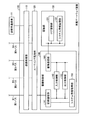
図14は、本実施形態の車載ゲートウェイ装置100の機能的な構成例を示すブロック図である。本実施形態の車載ゲートウェイ装置100では、図14に示すように、データ管理部160が追加されている。データ管理部160は、蓄積部130に蓄積されたECUが出力するデータやECUのファームウェアに関する情報を削除する処理を行う。なお、図14では、データ管理部160が蓄積制御部140に組み込まれた例を示しているが、データ管理部160は蓄積部130に蓄積されたECUが出力するデータやECUのファームウェアに関する情報を削除できる構成であればよい。また、図14は、図13に示した構成の車載ゲートウェイ装置100にデータ管理部160を追加した構成例を示しているが、第1実施形態や第2実施形態において開示したいずれの構成の車載ゲートウェイ装置100にデータ管理部160を追加してもよい。
FIG. 14 is a block diagram illustrating a functional configuration example of the in-
上述したように、ECUが出力するデータは膨大な量になるが蓄積部130の容量は有限であるため、すべてのデータを蓄積し続けることはできない。また、ECUによっては定期的にデータを出力するものもある。それらのECUが出力するデータの種類は動画データや数値データなど様々なものがある。一般的に動画データは容量が大きく、数値データは容量が小さいといったように、データサイズはデータの種類によって異なるため、同じ時間のデータであってもECUによって出力するデータサイズが異なる。例えば、数値データを出力するECUと動画データを出力するECUがあり、これらのECUが同一時間内に出力するデータを蓄積部130に蓄積すると、動画データを出力するECUが出力したデータが蓄積部130の容量の大半を占めるといったようなことが起き得る。
As described above, the amount of data output by the ECU is enormous, but the capacity of the
そこで、データ管理部160は、データの種類に応じて蓄積部130に蓄積されたデータを削除するタイミングを制御し、データを削除する処理を行う。例えば、動画データはX時間が経過したら削除し、数値データはY時間が経過したら削除するといったように、データの種類に応じて削除するタイミングを制御する。
Therefore, the
他にも、データの種類に応じて蓄積部130に蓄積するデータサイズの上限を予め定めておき、上限を超えた分については古いデータから削除していく方法を取ってもよい。例えば、動画データの場合には上限のデータサイズX、数値データの場合には上限のデータサイズYを定めておく。このとき、動画データについて上限のデータサイズXに達しているが、数値データについては上限のデータサイズYに達していないとする。ここで新しい動画データを蓄積部130に蓄積する場合は、仮に数値データ用の容量に空きがあったとしても古い動画データを削除し、その代わりに新しい動画データを蓄積する。
In addition, a method may be adopted in which an upper limit of the data size stored in the
なお、以上はデータの種類に応じて蓄積部130に蓄積されたデータを削除するタイミングを制御する例を説明したが、蓄積部130に蓄積されたデータがどのECUから出力されたデータであるかによって、そのデータを削除するタイミングを制御してもよい。つまり、あるECUが出力するデータはX時間が経過したら削除し、別のECUが出力するデータはY時間が経過したら削除するといったように、ECUごとにデータを削除するタイミングを制御してもよい。
In the above description, the example of controlling the timing of deleting the data stored in the
また、ログ蓄積部131とシステム情報蓄積部132に蓄積された各データの削除を別々に制御してもよい。ログ蓄積部131に蓄積されるデータはECUが出力するデータであり、特に車載システム10が動作している間は新しいデータが次々に入力され、故障が起きたり攻撃を受けたりしたことを確認するために用いられる。一方、システム情報蓄積部132に蓄積されるデータはECUのファームウェアに関する情報であるが、ECUのファームウェアがアップデートされる頻度は高くない。そこで、データ管理部160は、これらのデータを削除するタイミングを別々に管理してもよい。
The deletion of each data stored in the
また、以上は蓄積部130に蓄積するデータのサイズが容量を超えた場合を想定していたが、蓄積部130から外部装置に出力したデータを削除するようにしてもよい。車載システム10は、第1外部通信処理部21、第2外部通信処理部23、第3外部通信処理部24、または診断用通信部11を介して外部装置と接続することができる。そこで、ネットワークを介して外部装置に蓄積部130のデータを送信することで、蓄積部130の容量が一杯になることを避けることができる。この外部装置はPCやスマートフォン、USBメモリのような装置であってもよいし、クラウドサーバのようなサーバシステムであってもよい。
Further, the above description assumes that the size of the data stored in the
データ管理部160は、蓄積部130に蓄積されたデータがルーティング処理部120を介して外部装置に送信された場合に、その送信したデータを蓄積部130から削除する処理を行う。なお、データ管理部160は、ログ蓄積部131に蓄積されたデータは削除するが、システム情報蓄積部132に蓄積されたECUのファームウェアに関する情報は、外部装置に送信したとしても削除しないことが望ましい。ECUのファームウェアに関する情報は、車載システム10内で管理されていることが望まれるためである。
When the data stored in the
また、車載システム10を搭載した車両の所有者が変わることも考えられ、このような場合にはプライバシを考慮した対策が求められる。すなわち、ログ蓄積部131に蓄積されたECUが出力するデータには、様々なプライバシに関する情報が含まれる場合がある。例えば、車両の位置情報(GPS情報)と車両を運転した時刻情報が蓄積されていると、その所有者がどの時刻にどの場所にいたかが分かってしまう。他にも、ログ蓄積部131には車両がどの経路で走行したか、映像処理ECU20でどのようなルート検索を行ったか、映像処理ECU20でどのようなレストランの検索を行ったか、映像処理ECU20でどのような映像コンテンツを閲覧したか、シート調整をどのように行ったのかといった情報が、ログ蓄積部131に蓄積されたデータに含まれている場合がある。したがって、車載システム10を搭載した車両の所有者が変わる場合には、以前の所有者のプライバシに関する情報を完全に削除できることが望ましい。
Moreover, it is conceivable that the owner of the vehicle on which the in-
プライバシを考慮した車載ゲートウェイ装置100の構成例を図15に示す。図15に示す車載ゲートウェイ装置100は、図14に示した構成に対してプライバシ情報管理部170が追加されている。
FIG. 15 shows a configuration example of the in-
プライバシ情報管理部170は、ログ蓄積部131に蓄積されたプライバシに関連する情報を削除するようログ蓄積部131に指示する。ログ蓄積部131に蓄積されているECUが出力したデータのうち、どのデータがプライバシに関連するデータに該当するかは、予めプライバシ情報管理部170に設定していてもよいし、ECUから該当するデータを選定してもよいし、ルーティング処理部120を経由して外部装置から指示してもよい。
The privacy
また、不正にプライバシ情報が削除されることを防止するために、第1外部通信処理部21、第2外部通信処理部23、第3外部通信処理部24、あるいは診断用通信部11を経由して外部装置と認証処理を行い、認証が成功した場合のみプライバシ情報の削除を許可するように構成してもよい。その場合の車載ゲートウェイ装置100の構成例を図16に示す。
Further, in order to prevent the privacy information from being deleted illegally, the first external communication processing unit 21, the second external
図16に示す車載ゲートウェイ装置100は、図15に示した構成に対して認証処理部180が追加されている。認証処理部180は、ECUまたは外部装置に対する認証処理を行う。認証方式としては、パスワード認証やRSAなどの公開鍵アルゴリズムを用いた公開鍵認証を用いればよい。認証処理部180は、認証が成功した場合に、認証が成功したことをプライバシ情報管理部170に通知する。プライバシ情報管理部170は、認証処理部180から認証成功の通知を受けた場合に限り、ログ蓄積部131に対してプライバシ情報を削除するよう指示する。
The in-
さらに、オペレータが別な種類の車両に買い換えたり、故障によって同じ種類の車両に乗り換えたりする場合も考えられる。このような場合には、ログ蓄積部131に蓄積されたプライバシ情報を他の車両の車載システム10に移行できるようにすることが求められる。すなわち、運転支援制御ECU22はオペレータの操作の癖の情報を入力とし、学習アルゴリズムによって快適な運転ができるように制御する。オペレータが車両を乗り換えた場合、これらの癖の情報がリセットされてしまい、新たに学習を始めると乗り換え当初は快適な運転制御が実現できなくなる。そこで、ログ蓄積部131に蓄積されたプライバシ情報を新しい車両に引き継ぐことが求められる。
Furthermore, it may be considered that the operator buys another type of vehicle or changes to the same type of vehicle due to a failure. In such a case, it is required that the privacy information stored in the
このような場合、プライバシ情報管理部170がログ蓄積部131からプライバシ情報を取得し、外部装置などに送信する。一方、別の車両に搭載された車載システム10は、外部装置からオペレータのプライバシ情報を入力し、ログ蓄積部131に格納する。このとき、プライバシ情報の漏えいを防止するため、プライバシ情報の送信に先立ち、認証処理部180による認証処理を行ってもよい。また、プライバシ情報を送信した後、ログ蓄積部131から送信した情報を削除してもよい。
In such a case, the privacy
以上のように、本実施形態の車載ゲートウェイ装置100は、蓄積部130に蓄積したデータを削除する機能を備えることで、蓄積部130のデータあふれを有効に防止することができる。また、プライバシ情報の削除や引き継ぎを行う機能を備えることで、プライバシに配慮しつつ、車両の所有者が変更されたり、車両を乗り換えたりする場合にも適切な対応を図ることができる。
As described above, the in-
<変形例>
さて、信頼性の高いデータ削除方式を規模の大きなデータに適用する場合、所要時間がかかったり、媒体疲弊を招いたりする場合がある。そこで、本変形例では、所定単位のグループごとに共通の暗号鍵を用いて、ログ蓄積部131に蓄積するデータを暗号化し、その暗号化処理に利用した暗号鍵を削除(あるいは新しい鍵で上書き)する構成とすることで、高速かつ信頼性の高いデータの無効化を可能とする。ここでのデータの無効化とは、データを復号できない状態にすることであり、上述したデータの削除と同様の効果がある。所定単位は、所定サイズのデータ単位であってもよいし、データ種類やデータの用途あるいは蓄積部130の領域ごとなどでグルーピングして暗号鍵を用意してもよい。このようにすることで、鍵自体の更新頻度を下げることができる。
<Modification>
When a highly reliable data deletion method is applied to large-scale data, it may take a long time or cause medium exhaustion. Therefore, in this modification, data stored in the
本変形例の入力制御部142は、少なくとも、第1暗号処理部202と鍵管理部203とを有する。そして、鍵管理部203は、データ管理部160からの削除要求に応じて当該データの暗号処理に利用する鍵を更新・削除する。真正性・完全性を確保するための暗号処理とは異なる単位で暗号鍵を利用してもよい。このようにすることで、削除される単位と、ログの正当性を主張する単位とが異なる場合にも対応できる。
The
鍵管理部203は、暗号鍵生成を高速に実施するための乱数生成部を備えていたり、多くの暗号鍵を事前に生成し、蓄積しておく機能を備えていたりしてもよい。
The
このような構成とすることで、鍵データという少量のデータを削除するだけで、それによって暗号化されたデータを無効化できる。データの消去に時間のかかる記憶媒体にデータが蓄積されている場合に有効である。また、蓄積部130の物理的な記録箇所が離れて記録されていたとしても一度にデータを無効化できる。この性質は、例えばデータ消去オペレーションがブロックごとに必要なフラッシュメモリなどの記憶媒体において、複数ブロックに分散したデータを無効化するのに特に有効である。ログ蓄積部131に蓄積されるデータは時系列に書き込まれるが、消去したいデータが時系列に生じるとは限らない。この場合は、管理対象のデータが複数のブロックに分散することが起こりえるが、このような場合でも、データの無効化を効率的に実施できる。
With such a configuration, it is possible to invalidate the encrypted data only by deleting a small amount of data called key data. This is effective when data is stored in a storage medium that takes time to erase data. Further, even if the physical recording location of the
また、ログ蓄積部131に蓄積するデータを暗号化するための暗号鍵(便宜上、データ暗号鍵と呼ぶ)に加えて、このデータ暗号鍵を暗号・復号するための暗号鍵(便宜上、鍵暗号鍵と呼ぶ)を考える。この場合の構成を図17に示す。図17に示す構成例は、蓄積部130に暗号鍵記録部133が新たに備わっている点が図16とは異なる。
In addition to an encryption key for encrypting data stored in the log storage unit 131 (referred to as a data encryption key for convenience), an encryption key for encrypting / decrypting this data encryption key (for convenience, a key encryption key) Called). The configuration in this case is shown in FIG. The configuration example shown in FIG. 17 is different from FIG. 16 in that the
これまでの構成では鍵管理部203でデータ暗号鍵を管理していたが、図17に示す構成の場合は、鍵暗号鍵を鍵管理部203で管理する。そして、暗号化されたデータ暗号鍵を、蓄積部130の暗号鍵記録部133で管理する。鍵管理部203では、暗号鍵記録部133に蓄積された暗号化されたデータ暗号鍵を、鍵暗号鍵により復号した上で第1暗号処理部202や第3暗号処理部306に供給したり、暗号鍵記録部133に蓄積するデータ暗号鍵を鍵暗号鍵で暗号してから蓄積したり、データ管理部160からの要求に応じてデータ鍵を削除したりする。
In the configuration so far, the data encryption key is managed by the
データ暗号鍵を複数用意し、データはデータ種別やデータの用途あるいは蓄積部の領域ごとなどでグルーピングして、それぞれ異なるデータ暗号鍵で暗号化する。複数のデータ暗号鍵は同一の鍵暗号鍵で暗号、復号される。これにより、単一の鍵暗号鍵を消去することで、その鍵暗号鍵で暗号化された複数の暗号鍵を用いて暗号化されたデータを一括して無効化することができる。また、少量データである鍵暗号鍵をLSIチップ内など比較的物理攻撃(低速バスのプローブ、データ改ざん、チップ取り外して付け替え・不正利用)に対して強固な箇所(オンチップフラッシュなど)に記憶して、暗号化されたデータ暗号鍵を相対的に物理攻撃に弱い記録媒体に配置しても安全性を確保することができる。 A plurality of data encryption keys are prepared, and data is grouped according to data type, data application, storage area, etc., and encrypted with different data encryption keys. A plurality of data encryption keys are encrypted and decrypted with the same key encryption key. Thus, by erasing a single key encryption key, data encrypted using a plurality of encryption keys encrypted with the key encryption key can be invalidated collectively. Also, key encryption keys, which are small amounts of data, are stored in relatively strong locations (on-chip flash etc.) against relatively physical attacks (such as low-speed bus probes, data tampering, chip removal, replacement, and unauthorized use), such as in LSI chips. Thus, safety can be ensured even if the encrypted data encryption key is arranged on a recording medium that is relatively vulnerable to physical attacks.
なお、図17では暗号鍵記録部133は蓄積部130に設けられていたが、暗号化されたデータ暗号鍵を蓄積部130とは別の領域に格納してもよい。その場合の構成を図18に示す。図18に示す構成例は、鍵蓄積部190を新たに備え、この鍵蓄積部190に、暗号化されたデータ暗号鍵を蓄積する暗号鍵記録部191が設けられている点が図17とは異なる。
In FIG. 17, the encryption
図18に示す構成例では、暗号化されたデータ暗号鍵を、ログ蓄積部131やシステム情報蓄積部132を有する蓄積部130とは異なる記憶媒体である鍵蓄積部190に記録する。その上で、各記憶媒体の特性を考慮して、暗号鍵とデータの蓄積媒体を使い分けることで、最適かつ信頼性の高い車載ゲートウェイ装置100を実現できる。一例としては、重要なデータだが小容量である暗号鍵をビットコストが高く書き換え可能回数などの特性に優れた記録媒体に記録し、大容量であるログデータをより安価な記録媒体に記録する。
In the configuration example illustrated in FIG. 18, the encrypted data encryption key is recorded in a
上記のような削除方式に対する配慮は、特に信頼性とリアルタイム性が要求される車載向けの情報記録部を実現する上で特に効果が大きい。 Consideration for the deletion method as described above is particularly effective in realizing an in-vehicle information recording unit that is particularly required to be reliable and real-time.
<第4実施形態>
車載システム10において車載ゲートウェイ装置100が処理すべきデータ量は多いため、第1実施形態のように、ルーティング処理部120内のフィルタリング処理部121や蓄積制御部140内の入力制御部142によって、蓄積部130に蓄積するデータを選別することは必要である。また、この処理を固定的なものではなく、データ量に応じて変更することでログ機構の可用性を確保することもできる。本実施形態は、このような処理の変更を悪用した攻撃を防ぐための構成例である。
<Fourth embodiment>
Since the in-
攻撃者は、目的の達成に向けて自身が攻撃できる範囲を拡大しようとすることがある。ここでは、車載ゲートウェイ装置100に不正アクセスした攻撃者が、自身の不正アクセスできる範囲を拡大しようとする場面を想定する。この攻撃者は、フィルタリング処理部121によるデータ選別のポリシーや入力制御部142によるデータ選別のルールがデータ量に応じて変更されるように、実際には受信していないデータを直接ルーティング処理部120や蓄積制御部140に入力する。これにより、車載ゲートウェイ装置100は、攻撃者によって入力された架空のデータをもとに、フィルタリング処理部121や入力制御部142が蓄積部130に蓄積するデータを選別するような新たな動作をする。攻撃者は、この新たな動作では蓄積部130にデータが蓄積されないような不正アクセスを実施する。このように、ログ機構の可用性のための機構を悪用する攻撃がある。本実施形態は、このような攻撃への対策を鑑みたものである。
Attackers may try to expand the range they can attack to achieve their goals. Here, it is assumed that an attacker who has illegally accessed the in-
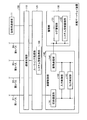
図19は、本実施形態の車載ゲートウェイ装置100の機能的な構成例を示すブロック図である。図2に示した第1実施形態の構成と比較して、監視部400が追加されている点が異なる。監視部400は、車載ゲートウェイ装置100の各部と接続されるが、通信処理部110、ルーティング処理部120、蓄積部130および蓄積制御部140とは、独立したCPUコアとメモリあるいはHW機構により実現される。
FIG. 19 is a block diagram illustrating a functional configuration example of the in-
本実施形態の車載ゲートウェイ装置100において、監視部400は各バスをモニタリングし、例えばフィルタリング処理部121のポリシーや入力制御部142のルールを変更する前に、そのポリシー変更やルール変更の要因となるイベントが実際に発生しているかを確認する。例えば、蓄積部130の容量監視に伴うポリシーの変更が要求された場合には、監視部400が、独立に蓄積部130の容量を確認することで、ルーティング処理部120が不正アクセスされていないことを確認する。また、例えば、ルーティング処理部120からのデータ入力量が大きいために、入力制御部142が蓄積部130に送るデータ種類やデータ量を減らしたりするようにルールの変更が要求された場合には、監視部400が、通信処理部110の入出力のデータ量を確認することで、蓄積制御部140が不正にアクセスされていないことを確認する。また、監視部400が蓄積部130の容量を確認することで、データ消去のきっかけとなるイベントの情報を蓄積制御部140に捏造して送ってデータを消去させるような攻撃にも対応できる。
In the in-
以上のように、本実施形態の車載ゲートウェイ装置100は、蓄積部130に蓄積するデータを選別するポリシーやルールの変更が要求された場合に、監視部400が、そのポリシー変更やルール変更の要因となるイベントが実際に発生しているかを確認するようにしている。したがって、車載ゲートウェイ装置100に不正アクセスした攻撃者による攻撃の痕跡消去のための試みを防ぐことができる。
As described above, when the in-
<補足説明>
以上説明した実施形態の車載ゲートウェイ装置100の機能的な構成要素は、例えば、ハードウェアとソフトウェア(プログラム)との協働により実現することができる。ハードウェアとしては、各種のハードウェアプロセッサ、揮発、不揮発のメモリ、メモリコントローラ、通信モジュールなど、車載ゲートウェイ装置100をコンピュータシステムとして動作させるものがある。このようなコンピュータシステム上で所定のプログラムが実行されることにより、上述した車載ゲートウェイ装置100の機能的な構成要素を実現することができる。
<Supplementary explanation>
The functional components of the in-
車載ゲートウェイ装置100の機能的な構成要素を実現するプログラムは、例えば、不揮発のメモリに予め組み込んで提供される。また、上記プログラムは、インストール可能な形式または実行可能な形式のファイルでコンピュータ読み取り可能な記録媒体に記録されて提供されるようにしてもよい。また、上記プログラムを、インターネットなどのネットワークに接続されたコンピュータ上に格納し、ネットワーク経由でダウンロードさせることにより提供するように構成してもよい。また、上記プログラムを、インターネットなどのネットワーク経由で提供または配布するように構成してもよい。なお、車載ゲートウェイ装置100における上述した機能的な構成要素は、その一部または全部を、ASICやFPGAなどの専用のハードウェアを用いて実現することも可能である。
A program for realizing functional components of the in-
以上、本発明の実施形態を説明したが、この実施形態は例として提示したものであり、発明の範囲を限定することは意図していない。この新規な実施形態は、その他の様々な形態で実施されることが可能であり、発明の要旨を逸脱しない範囲で、種々の省略、置き換え、変更を行うことができる。これら実施形態やその変形は、発明の範囲や要旨に含まれるとともに、特許請求の範囲に記載された発明とその均等の範囲に含まれる。 As mentioned above, although embodiment of this invention was described, this embodiment is shown as an example and is not intending limiting the range of invention. The novel embodiment can be implemented in various other forms, and various omissions, replacements, and changes can be made without departing from the scope of the invention. These embodiments and modifications thereof are included in the scope and gist of the invention, and are included in the invention described in the claims and the equivalents thereof.
10 車載システム
12 エンジン制御ECU
13 ステアリング制御ECU
14 ブレーキ制御ECU
15 ライト制御ECU
16 エアバッグ制御ECU
17 空調制御ECU
18 センサECU
19 座席制御ECU
20 映像処理ECU
22 運転支援制御ECU
100 車載ゲートウェイ装置
110 通信処理部
120 ルーティング処理部
130 蓄積部
131 ログ蓄積部
132 システム情報蓄積部
140 蓄積制御部
142 入力制御部
143 出力制御部
150 システム情報取得部
160 データ管理部
170 プライバシ情報管理部
201 選別処理部
202 第1暗号処理部
301 アクセス制御部
302 モード設定部
304 第2暗号処理部
306 第3暗号処理部
400 監視部
10 On-
13 Steering control ECU
14 Brake control ECU
15 Light control ECU
16 Airbag control ECU
17 Air-conditioning control ECU
18 Sensor ECU
19 Seat control ECU
20 Video processing ECU
22 Driving support control ECU
DESCRIPTION OF
Claims (22)
前記車載システムに含まれる電子制御ユニットが出力するデータを蓄積する蓄積部と、
少なくとも一つの電子制御ユニットが接続される内部通信処理部を含む複数の内部通信処理部と、
前記複数の内部通信処理部の間でデータを転送するとともに、転送したデータの少なくとも一部を前記蓄積部に蓄積可能に出力するルーティング処理部と、
前記蓄積部に蓄積するデータと前記蓄積部から出力するデータとの少なくともいずれかを所定のルールに従って加工または選別する蓄積制御部と、を備える車載ゲートウェイ装置。 An in-vehicle gateway device installed in an in-vehicle system,
An accumulator that accumulates data output by an electronic control unit included in the in-vehicle system;
A plurality of internal communication processing units including an internal communication processing unit to which at least one electronic control unit is connected;
A routing processing unit that transfers data between the plurality of internal communication processing units and outputs at least a part of the transferred data so as to be stored in the storage unit;
An in-vehicle gateway device comprising: an accumulation control unit that processes or sorts at least one of data accumulated in the accumulation unit and data output from the accumulation unit according to a predetermined rule.
前記蓄積制御部は、前記蓄積部から出力するデータの出力先が前記外部機器である場合は、当該データを暗号化する、請求項1乃至4のいずれか一項に記載の車載ゲートウェイ装置。 A diagnostic communication unit for transmitting data output by the electronic control unit to an external device;
The in-vehicle gateway device according to any one of claims 1 to 4, wherein the storage control unit encrypts the data when the output destination of the data output from the storage unit is the external device.
前記蓄積部は、前記電子制御ユニットが出力するデータと、前記情報取得部が取得した前記ファームウェアに関する情報とを蓄積する、請求項1乃至8のいずれか一項に記載の車載ゲートウェイ装置。 An information acquisition unit that acquires information about firmware of the electronic control unit;
The in-vehicle gateway device according to any one of claims 1 to 8, wherein the storage unit stores data output from the electronic control unit and information about the firmware acquired by the information acquisition unit.
前記情報取得部は、復号した前記ファームウェアが、前記電子制御ユニットが接続される内部通信処理部に転送される際に前記ファームウェアに関する情報を取得する、請求項9に記載の車載ゲートウェイ装置。 The routing processing unit decrypts the firmware that has been encrypted and transmitted from an external device and transfers the decrypted firmware to an internal communication processing unit to which the electronic control unit is connected,
The in-vehicle gateway device according to claim 9, wherein the information acquisition unit acquires information about the firmware when the decoded firmware is transferred to an internal communication processing unit to which the electronic control unit is connected.
前記データ管理部は、前記鍵を削除または上書きすることで、前記蓄積部が蓄積する、前記鍵を用いて暗号化されたデータを無効化する、請求項14乃至17のいずれか一項に記載の車載ゲートウェイ装置。 The accumulation control unit encrypts data output from the electronic control unit using a common key for each group of predetermined units,
18. The data management unit according to any one of claims 14 to 17, wherein the data management unit invalidates data stored in the storage unit and encrypted using the key by deleting or overwriting the key. In-vehicle gateway device.
前記データ管理部は、前記暗号化鍵を削除または上書きすることで、前記蓄積部が蓄積する、前記鍵を用いて暗号化されたデータを無効化する、請求項18に記載の車載ゲートウェイ装置。 The accumulation control unit further encrypts a plurality of the keys using a common key encryption key,
The in-vehicle gateway device according to claim 18, wherein the data management unit invalidates data encrypted using the key stored in the storage unit by deleting or overwriting the encryption key.
前記車載ゲートウェイ装置は、
前記車載システムに含まれる電子制御ユニットが出力するデータを蓄積する蓄積部を備え、
少なくとも一つの電子制御ユニットが接続される内部通信処理部を含む複数の内部通信処理部の間でデータを転送するとともに、転送したデータの少なくとも一部を前記蓄積部に蓄積可能に出力する工程と、
前記蓄積部に蓄積するデータと前記蓄積部から出力するデータとの少なくともいずれかを所定のルールに従って加工または選別する工程と、を含む蓄積制御方法。 A storage control method executed in an in-vehicle gateway device mounted in an in-vehicle system,
The in-vehicle gateway device is
An accumulation unit for accumulating data output by an electronic control unit included in the in-vehicle system;
Transferring data between a plurality of internal communication processing units including an internal communication processing unit to which at least one electronic control unit is connected, and outputting at least a part of the transferred data to be able to be stored in the storage unit; ,
A process for controlling or sorting at least one of data stored in the storage unit and data output from the storage unit according to a predetermined rule.
前記車載システムに含まれる電子制御ユニットが出力するデータを蓄積する蓄積部の機能と、
少なくとも一つの電子制御ユニットが接続される内部通信処理部を含む複数の内部通信処理部の機能と、
前記複数の内部通信処理部の間でデータを転送するとともに、転送したデータの少なくとも一部を前記蓄積部に蓄積可能に出力するルーティング処理部の機能と、
前記蓄積部に蓄積するデータと前記蓄積部から出力するデータとの少なくともいずれかを所定のルールに従って加工または選別する蓄積制御部の機能と、を実現させるためのプログラム。 In-vehicle gateway device mounted on in-vehicle system
A function of a storage unit for storing data output by an electronic control unit included in the in-vehicle system;
Functions of a plurality of internal communication processing units including an internal communication processing unit to which at least one electronic control unit is connected;
A function of a routing processing unit that transfers data between the plurality of internal communication processing units and outputs at least a part of the transferred data so as to be stored in the storage unit;
A program for realizing a function of an accumulation control unit that processes or sorts at least one of data accumulated in the accumulation unit and data output from the accumulation unit according to a predetermined rule.
Priority Applications (3)
| Application Number | Priority Date | Filing Date | Title |
|---|---|---|---|
| JP2016058798A JP2017174111A (en) | 2016-03-23 | 2016-03-23 | In-vehicle gateway device, storage control method, and program |
| US15/436,031 US10229547B2 (en) | 2016-03-23 | 2017-02-17 | In-vehicle gateway device, storage control method, and computer program product |
| EP17157011.2A EP3223466A1 (en) | 2016-03-23 | 2017-02-20 | In-vehicle gateway device, storage control method and computer-readable medium |
Applications Claiming Priority (1)
| Application Number | Priority Date | Filing Date | Title |
|---|---|---|---|
| JP2016058798A JP2017174111A (en) | 2016-03-23 | 2016-03-23 | In-vehicle gateway device, storage control method, and program |
Publications (1)
| Publication Number | Publication Date |
|---|---|
| JP2017174111A true JP2017174111A (en) | 2017-09-28 |
Family
ID=58191263
Family Applications (1)
| Application Number | Title | Priority Date | Filing Date |
|---|---|---|---|
| JP2016058798A Pending JP2017174111A (en) | 2016-03-23 | 2016-03-23 | In-vehicle gateway device, storage control method, and program |
Country Status (3)
| Country | Link |
|---|---|
| US (1) | US10229547B2 (en) |
| EP (1) | EP3223466A1 (en) |
| JP (1) | JP2017174111A (en) |
Cited By (8)
| Publication number | Priority date | Publication date | Assignee | Title |
|---|---|---|---|---|
| JP2019103006A (en) * | 2017-12-04 | 2019-06-24 | トヨタ自動車株式会社 | On-vehicle relay device, information processing device, relay device, information processing method, program, information processing system, vehicle, and external device |
| US10380057B2 (en) | 2017-03-17 | 2019-08-13 | Kabushiki Kaisha Toshiba | Data storage device |
| KR20200020515A (en) * | 2018-08-17 | 2020-02-26 | 재단법인대구경북과학기술원 | Controller area network system and message authentication method |
| US10803683B2 (en) | 2017-02-14 | 2020-10-13 | Kabushiki Kaisha Toshiba | Information processing device, information processing method, computer program product, and moving object |
| WO2022045007A1 (en) * | 2020-08-25 | 2022-03-03 | 株式会社デンソー | Data recording device |
| WO2022050108A1 (en) * | 2020-09-07 | 2022-03-10 | ソニーセミコンダクタソリューションズ株式会社 | Information processing device, information processing method, program, and information processing terminal |
| JPWO2024069264A1 (en) * | 2022-09-26 | 2024-04-04 | ||
| JPWO2024143201A1 (en) * | 2022-12-28 | 2024-07-04 |
Families Citing this family (33)
| Publication number | Priority date | Publication date | Assignee | Title |
|---|---|---|---|---|
| KR102328803B1 (en) * | 2014-12-16 | 2021-11-22 | 삼성전자주식회사 | Electronic device and method for determining an abnormal state of a connector |
| US11791882B2 (en) | 2016-04-13 | 2023-10-17 | Qualcomm Incorporated | System and method for beam management |
| US10425200B2 (en) | 2016-04-13 | 2019-09-24 | Qualcomm Incorporated | System and method for beam adjustment request |
| US10756868B2 (en) | 2016-07-01 | 2020-08-25 | Qualcomm Incorporated | Techniques for transmitting a physical uplink shared channel in an uplink pilot time slot |
| CN109215170B (en) * | 2017-07-04 | 2021-03-02 | 百度在线网络技术(北京)有限公司 | Driving data storage method, device and equipment |
| EP3590037A4 (en) * | 2017-07-25 | 2020-07-08 | Aurora Labs Ltd | CONSTRUCTION OF SOFTWARE DELTA UPDATES FOR VEHICLE ECU SOFTWARE AND ANOMALITY DETECTION BASED ON A TOOLCHAIN |
| WO2019021403A1 (en) * | 2017-07-26 | 2019-01-31 | パナソニック インテレクチュアル プロパティ コーポレーション オブ アメリカ | Control network system, vehicle remote control system, and vehicle-mounted relay device |
| US11475723B2 (en) * | 2017-12-29 | 2022-10-18 | Robert Bosch Gmbh | Determining a fault in an electronic controller |
| CN108382324A (en) * | 2018-01-18 | 2018-08-10 | 沈阳中科唯电子技术有限公司 | A kind of low-power consumption entire car controller of integrated gateway function |
| JP7030559B2 (en) * | 2018-02-27 | 2022-03-07 | 本田技研工業株式会社 | Data registration system |
| US10846955B2 (en) | 2018-03-16 | 2020-11-24 | Micron Technology, Inc. | Black box data recorder for autonomous driving vehicle |
| US11094148B2 (en) * | 2018-06-18 | 2021-08-17 | Micron Technology, Inc. | Downloading system memory data in response to event detection |
| EP3836067A4 (en) * | 2018-08-10 | 2022-04-27 | Pioneer Corporation | Data structure, storage medium, storage device, and receiver |
| JP7061055B2 (en) * | 2018-11-06 | 2022-04-27 | 日立Astemo株式会社 | Steering device |
| DE102018220008A1 (en) | 2018-11-22 | 2020-05-28 | Robert Bosch Gmbh | Method for operating a control device of a vehicle |
| US11782605B2 (en) | 2018-11-29 | 2023-10-10 | Micron Technology, Inc. | Wear leveling for non-volatile memory using data write counters |
| US11410475B2 (en) | 2019-01-31 | 2022-08-09 | Micron Technology, Inc. | Autonomous vehicle data recorders |
| US11373466B2 (en) | 2019-01-31 | 2022-06-28 | Micron Technology, Inc. | Data recorders of autonomous vehicles |
| JP2020167607A (en) * | 2019-03-29 | 2020-10-08 | マツダ株式会社 | Computational system for automobiles and processing method of received data |
| CN111901212B (en) * | 2019-05-06 | 2022-05-17 | 上汽通用汽车有限公司 | Method for refreshing electronic control module based on various different communication protocols of vehicle-mounted bus |
| KR102167906B1 (en) * | 2019-06-20 | 2020-10-20 | 주식회사 만도 | Apparatus for controlling steering and System for assisting steering including it |
| JP7115442B2 (en) * | 2019-08-21 | 2022-08-09 | トヨタ自動車株式会社 | Determination device, determination system, program and determination method |
| JP7230760B2 (en) * | 2019-09-30 | 2023-03-01 | トヨタ自動車株式会社 | Relay device and external device |
| US20210183175A1 (en) * | 2019-12-12 | 2021-06-17 | Explication Automation, Llc | System of privacy oriented automated electric vehicle miles traveled usage fee assessment and settlement using utility smart grid communication network |
| CN111145389B (en) * | 2019-12-31 | 2022-03-04 | 中国第一汽车股份有限公司 | Vehicle data management method and system |
| EP3883235A1 (en) * | 2020-03-17 | 2021-09-22 | Aptiv Technologies Limited | Camera control modules and methods |
| KR102917603B1 (en) * | 2020-06-24 | 2026-01-27 | 현대자동차주식회사 | Data processing Device and Vehicle having the same |
| CN112187599B (en) * | 2020-09-15 | 2022-04-08 | 郑州信大捷安信息技术股份有限公司 | System and method for supporting data communication between network buses in vehicle |
| JP7484633B2 (en) * | 2020-09-30 | 2024-05-16 | 株式会社デンソー | Shared storage management device and shared storage management method |
| CN115730340A (en) * | 2021-08-25 | 2023-03-03 | 华为技术有限公司 | A data processing method and related device |
| CN114884706B (en) * | 2022-04-24 | 2023-06-16 | 北京经纬恒润科技股份有限公司 | Vehicle-mounted message processing method and system |
| EP4652706A1 (en) | 2023-01-17 | 2025-11-26 | The Braun Corporation | Secondary communication bus for a modified vehicle |
| US20240367598A1 (en) * | 2023-05-02 | 2024-11-07 | Red Hat, Inc. | Application profiles in electronic control units |
Citations (13)
| Publication number | Priority date | Publication date | Assignee | Title |
|---|---|---|---|---|
| US6134660A (en) * | 1997-06-30 | 2000-10-17 | Telcordia Technologies, Inc. | Method for revoking computer backup files using cryptographic techniques |
| JP2002243591A (en) * | 2001-02-22 | 2002-08-28 | Mitsubishi Electric Corp | Vehicle failure diagnosis device |
| JP2003223402A (en) * | 2002-01-29 | 2003-08-08 | Mitsubishi Electric Corp | Mail sending device, mail receiving device, mail communication system, mail sending method and mail receiving method |
| JP2004260484A (en) * | 2003-02-25 | 2004-09-16 | Sumitomo Electric Ind Ltd | In-vehicle communication system and gateway device |
| JP2006309298A (en) * | 2005-04-26 | 2006-11-09 | Canon Inc | Image processing apparatus, control method therefor, and program |
| JP2007028376A (en) * | 2005-07-20 | 2007-02-01 | Yazaki Corp | In-vehicle LAN gateway device and external device capable of communicating with the gateway device |
| JP2010038619A (en) * | 2008-08-01 | 2010-02-18 | Hitachi Ltd | Navigation apparatus |
| JP2011000894A (en) * | 2009-06-16 | 2011-01-06 | Fujitsu Ten Ltd | Control device and control method |
| JP2014027517A (en) * | 2012-07-27 | 2014-02-06 | Toyota Motor Corp | Communication system and communication method |
| JP2014165641A (en) * | 2013-02-25 | 2014-09-08 | Toyota Motor Corp | Information processing device and information processing method |
| JP2015115023A (en) * | 2013-12-16 | 2015-06-22 | 株式会社島津製作所 | Log data processing system for analysis device system and program for system |
| US20150180840A1 (en) * | 2013-12-24 | 2015-06-25 | Hyundai Motor Company | Firmware upgrade method and system thereof |
| US20160035148A1 (en) * | 2014-07-29 | 2016-02-04 | GM Global Technology Operations LLC | Securely providing diagnostic data from a vehicle to a remote server using a diagnostic tool |
Family Cites Families (9)
| Publication number | Priority date | Publication date | Assignee | Title |
|---|---|---|---|---|
| US7962638B2 (en) * | 2007-03-26 | 2011-06-14 | International Business Machines Corporation | Data stream filters and plug-ins for storage managers |
| JP5017231B2 (en) | 2008-10-20 | 2012-09-05 | 日立オートモティブシステムズ株式会社 | Routing method in in-vehicle gateway device |
| JP5382131B2 (en) * | 2009-11-06 | 2014-01-08 | トヨタ自動車株式会社 | Vehicle gateway system |
| JP2011121425A (en) | 2009-12-09 | 2011-06-23 | Nec Corp | Onboard control system, radio communication system, method for controlling onboard control system and integrated communication ecu |
| JP5206801B2 (en) * | 2011-01-19 | 2013-06-12 | 株式会社デンソー | Vehicle behavior data storage control system, electronic control device |
| JP6024564B2 (en) * | 2013-03-28 | 2016-11-16 | 株式会社オートネットワーク技術研究所 | In-vehicle communication system |
| US9202595B2 (en) * | 2013-11-12 | 2015-12-01 | Micron Technology, Inc. | Post package repair of memory devices |
| US9840212B2 (en) | 2014-01-06 | 2017-12-12 | Argus Cyber Security Ltd. | Bus watchman |
| JP6408832B2 (en) * | 2014-08-27 | 2018-10-17 | ルネサスエレクトロニクス株式会社 | Control system, relay device, and control method |
-
2016
- 2016-03-23 JP JP2016058798A patent/JP2017174111A/en active Pending
-
2017
- 2017-02-17 US US15/436,031 patent/US10229547B2/en not_active Expired - Fee Related
- 2017-02-20 EP EP17157011.2A patent/EP3223466A1/en not_active Withdrawn
Patent Citations (13)
| Publication number | Priority date | Publication date | Assignee | Title |
|---|---|---|---|---|
| US6134660A (en) * | 1997-06-30 | 2000-10-17 | Telcordia Technologies, Inc. | Method for revoking computer backup files using cryptographic techniques |
| JP2002243591A (en) * | 2001-02-22 | 2002-08-28 | Mitsubishi Electric Corp | Vehicle failure diagnosis device |
| JP2003223402A (en) * | 2002-01-29 | 2003-08-08 | Mitsubishi Electric Corp | Mail sending device, mail receiving device, mail communication system, mail sending method and mail receiving method |
| JP2004260484A (en) * | 2003-02-25 | 2004-09-16 | Sumitomo Electric Ind Ltd | In-vehicle communication system and gateway device |
| JP2006309298A (en) * | 2005-04-26 | 2006-11-09 | Canon Inc | Image processing apparatus, control method therefor, and program |
| JP2007028376A (en) * | 2005-07-20 | 2007-02-01 | Yazaki Corp | In-vehicle LAN gateway device and external device capable of communicating with the gateway device |
| JP2010038619A (en) * | 2008-08-01 | 2010-02-18 | Hitachi Ltd | Navigation apparatus |
| JP2011000894A (en) * | 2009-06-16 | 2011-01-06 | Fujitsu Ten Ltd | Control device and control method |
| JP2014027517A (en) * | 2012-07-27 | 2014-02-06 | Toyota Motor Corp | Communication system and communication method |
| JP2014165641A (en) * | 2013-02-25 | 2014-09-08 | Toyota Motor Corp | Information processing device and information processing method |
| JP2015115023A (en) * | 2013-12-16 | 2015-06-22 | 株式会社島津製作所 | Log data processing system for analysis device system and program for system |
| US20150180840A1 (en) * | 2013-12-24 | 2015-06-25 | Hyundai Motor Company | Firmware upgrade method and system thereof |
| US20160035148A1 (en) * | 2014-07-29 | 2016-02-04 | GM Global Technology Operations LLC | Securely providing diagnostic data from a vehicle to a remote server using a diagnostic tool |
Cited By (14)
| Publication number | Priority date | Publication date | Assignee | Title |
|---|---|---|---|---|
| US10803683B2 (en) | 2017-02-14 | 2020-10-13 | Kabushiki Kaisha Toshiba | Information processing device, information processing method, computer program product, and moving object |
| US10380057B2 (en) | 2017-03-17 | 2019-08-13 | Kabushiki Kaisha Toshiba | Data storage device |
| JP2019103006A (en) * | 2017-12-04 | 2019-06-24 | トヨタ自動車株式会社 | On-vehicle relay device, information processing device, relay device, information processing method, program, information processing system, vehicle, and external device |
| JP7124303B2 (en) | 2017-12-04 | 2022-08-24 | トヨタ自動車株式会社 | Vehicle-mounted relay device, information processing device, relay device, information processing method, program, information processing system, and vehicle |
| KR20200020515A (en) * | 2018-08-17 | 2020-02-26 | 재단법인대구경북과학기술원 | Controller area network system and message authentication method |
| KR102148453B1 (en) | 2018-08-17 | 2020-08-27 | 재단법인대구경북과학기술원 | Controller area network system and message authentication method |
| JP2022037627A (en) * | 2020-08-25 | 2022-03-09 | 株式会社デンソー | Data recording apparatus |
| WO2022045007A1 (en) * | 2020-08-25 | 2022-03-03 | 株式会社デンソー | Data recording device |
| JP7512768B2 (en) | 2020-08-25 | 2024-07-09 | 株式会社デンソー | Data Recording Device |
| WO2022050108A1 (en) * | 2020-09-07 | 2022-03-10 | ソニーセミコンダクタソリューションズ株式会社 | Information processing device, information processing method, program, and information processing terminal |
| JPWO2024069264A1 (en) * | 2022-09-26 | 2024-04-04 | ||
| JPWO2024143201A1 (en) * | 2022-12-28 | 2024-07-04 | ||
| WO2024143201A1 (en) * | 2022-12-28 | 2024-07-04 | 株式会社デンソー | Access management device, access management system, access management program, and access management method |
| JP7772258B2 (en) | 2022-12-28 | 2025-11-18 | 株式会社デンソー | Access management device, access management system, access management program, and access management method |
Also Published As
| Publication number | Publication date |
|---|---|
| EP3223466A1 (en) | 2017-09-27 |
| US20170278320A1 (en) | 2017-09-28 |
| US10229547B2 (en) | 2019-03-12 |
Similar Documents
| Publication | Publication Date | Title |
|---|---|---|
| US10229547B2 (en) | In-vehicle gateway device, storage control method, and computer program product | |
| JP7197638B2 (en) | Security processing method and server | |
| CN110800249B (en) | Maintenance system and maintenance method | |
| CN103685214B (en) | Safety access method for vehicle electronic control unit | |
| CN109314640B (en) | Vehicle information collection system, vehicle-mounted computer, vehicle information collection device, vehicle information collection method, and recording medium | |
| US11356256B2 (en) | Secure vehicular part communication | |
| US20110083161A1 (en) | Vehicle, maintenance device, maintenance service system, and maintenance service method | |
| US11757911B2 (en) | Method and system for providing security on in-vehicle network | |
| US9767264B2 (en) | Apparatus, method for controlling apparatus, and program | |
| US11063747B2 (en) | Secure monitoring using block chain | |
| JP2010011400A (en) | Cipher communication system of common key system | |
| CN106030600A (en) | Authentication system and car onboard control device | |
| CN109714171B (en) | Safety protection method, device, equipment and medium | |
| Ammar et al. | Securing the on-board diagnostics port (obd-ii) in vehicles | |
| WO2019116922A1 (en) | Onboard updating device, program, and method for updating program or data | |
| US20200389325A1 (en) | In-vehicle-function access control system, in-vehicle apparatus, and in-vehicle-function access control method | |
| JP2013026964A (en) | Information update device for vehicle and information update method for vehicle | |
| US20070266250A1 (en) | Mobile Data Transmission Method and System | |
| US20240275581A1 (en) | Data storage system, mobile object, and non-transitory computer readable storage medium | |
| KR20190058302A (en) | Semiconductor device, authentication system, and authentication method | |
| KR102411797B1 (en) | Hardware-based vehicle cyber security system | |
| US20230015693A1 (en) | Restoration of corrupted keys in a secure storage system | |
| CN117479152A (en) | Vehicle machine debugging method, server, vehicle machine equipment and computer readable storage medium | |
| Mansor | Security and privacy aspects of automotive systems | |
| CN119603053B (en) | Communication data processing method, communication system and vehicle |
Legal Events
| Date | Code | Title | Description |
|---|---|---|---|
| A621 | Written request for application examination |
Free format text: JAPANESE INTERMEDIATE CODE: A621 Effective date: 20180222 |
|
| A977 | Report on retrieval |
Free format text: JAPANESE INTERMEDIATE CODE: A971007 Effective date: 20181116 |
|
| A131 | Notification of reasons for refusal |
Free format text: JAPANESE INTERMEDIATE CODE: A131 Effective date: 20181218 |
|
| A521 | Request for written amendment filed |
Free format text: JAPANESE INTERMEDIATE CODE: A523 Effective date: 20190213 |
|
| A02 | Decision of refusal |
Free format text: JAPANESE INTERMEDIATE CODE: A02 Effective date: 20190702 |