JP2017178376A - Cap with pluck plug - Google Patents
Cap with pluck plug Download PDFInfo
- Publication number
- JP2017178376A JP2017178376A JP2016068953A JP2016068953A JP2017178376A JP 2017178376 A JP2017178376 A JP 2017178376A JP 2016068953 A JP2016068953 A JP 2016068953A JP 2016068953 A JP2016068953 A JP 2016068953A JP 2017178376 A JP2017178376 A JP 2017178376A
- Authority
- JP
- Japan
- Prior art keywords
- plug
- cap
- upper lid
- knob
- knob member
- Prior art date
- Legal status (The legal status is an assumption and is not a legal conclusion. Google has not performed a legal analysis and makes no representation as to the accuracy of the status listed.)
- Granted
Links
Images


Landscapes
- Closures For Containers (AREA)
Abstract
【課題】 注出部がもぎり栓により密封されるキャップが装着された容器のもぎり栓を保護するとともに、簡単にもぎり栓を捻り取ることができ、また、容器の使用を確認できるもぎり栓付きキャップを提供すること。【解決手段】 注出部がもぎり栓により密封されるキャップ本体と、キャップ本体に開閉自在に取り付けられる上蓋とからなる、もぎり栓付きキャップであって、キャップ本体は、容器の口部に装着される装着部と、装着部内縁から内方に延設され口部の開口を封鎖する上壁と、上壁を貫通して形成される注出部と、注出部の先端部に破断可能に連設されるもぎり栓とを備え、上蓋は、閉蓋時に、もぎり栓の上部に破断可能に設けられる摘み部材を備え、摘み部材は、もぎり栓を覆い、掛止する係合筒部を備えることを特徴とする。【選択図】 図1PROBLEM TO BE SOLVED: To protect a cap attached to a container to which a spout portion is sealed by a plug, to easily twist the plug, and to confirm the use of the container. To provide. SOLUTION: This is a cap with a shaving plug, which comprises a cap body in which an injection portion is sealed by a shaving plug and an upper lid that can be opened and closed and attached to the cap body, and the cap body is attached to the mouth of a container. The mounting part, the upper wall extending inward from the inner edge of the mounting part to block the opening of the mouth, the pouring part formed through the upper wall, and the tip of the pouring part can be broken. It is provided with a series of hooking plugs, and the upper lid is provided with a gripping member fragilely provided on the upper part of the hooking plug when the lid is closed, and the picking member is provided with an engaging cylinder portion for covering and hooking the hooking plug. It is characterized by that. [Selection diagram] Fig. 1
Description
本発明は、使い切り容器などに用いるキャップに関し、とくに、注出部がもぎり栓により密封されるもぎり栓付きキャップに関するものである。 The present invention relates to a cap used for a single-use container or the like, and more particularly to a cap with a mortar plug in which a pouring portion is sealed with a mortar plug.
化粧液においては、外気に触れると変質し易いために比較的短期間に使い終ることを必要とするものがあり、このような液体収納容器は、外気が容器体内へ入ることを防止することが望まれ、さらに、消費者がその容器購入後は、密封保管することが容易であることを要する。
このような封緘容器として、容器口部にノズルなどの注出部を起立するとともに、注出部上端の注出孔を密閉するもぎり栓を破断可能な薄肉部を介して注出部上端から起立した容器と、容器の口筒部に装着され、もぎり栓を覆うとともに閉蓋するカバーキャップとからなり、使用時には、もぎり栓を捻り取ることにより、薄肉部を破断して注出孔を開口するものは、従来から知られている(例えば、特許文献1参照)。
Some cosmetic liquids need to be used in a relatively short period of time because they easily change in quality when exposed to the outside air. Such a liquid storage container can prevent outside air from entering the container body. It is also desirable that the consumer be easy to keep hermetically sealed after purchasing the container.
As such a sealed container, a pouring part such as a nozzle is erected at the mouth of the container, and it is erected from the upper end of the pouring part through a thin part that can break the mortar plug that seals the pouring hole at the upper end of the pouring part. And a cover cap that is attached to the mouth tube portion of the container and covers and closes the plug, and in use, the thin plug is broken to open the outlet hole by twisting off the plug. A thing is conventionally known (for example, refer patent document 1).
また、トイレの洗浄剤や配水管の洗浄剤や洗濯槽の洗浄剤など、塩素系の内容液が充填された容器は、開栓時に内容液が飛散するリスク低減するためや、使用後、手に内容液が付着するリスクを低減するために、もぎり栓付きの使い切りの容器が好ましい。 In addition, containers filled with chlorinated liquids such as toilet cleaners, water pipe cleaners, and washing tank cleaners can be used to reduce the risk of splattered contents when opened, or after use. In order to reduce the risk of content liquid adhering to the container, a single-use container with a mortar plug is preferred.
上記特許文献1記載の封緘容器では、注出孔を開口する際に、もぎり栓(つまみ部)を捻り取るために、カバーキャップを開蓋した後に、カバーキャップを反転させ、もぎり栓(つまみ部)をカバーキャップの頂部に設けた溝で挟持させ、カバーキャップを捻り、もぎり栓(つまみ部)とともに取り去るようにしており、注出孔を開口することが簡単ではなかった。
また、注出孔を開口した後に、カバーキャップを容器口部に装着すると、注出孔の開口が確認できず、容器を使用したかどうか確認できないという問題があった。
In the sealed container described in Patent Literature 1, when opening the pouring hole, in order to twist the mortar plug (knob portion), after opening the cover cap, the cover cap is inverted, and the mortar plug (knob portion) ) Is sandwiched by a groove provided on the top of the cover cap, and the cover cap is twisted and removed together with the mortar plug (knob portion). It was not easy to open the pouring hole.
Further, when the cover cap is attached to the container mouth after opening the pouring hole, there is a problem that the opening of the pouring hole cannot be confirmed and it cannot be confirmed whether or not the container has been used.
本発明は、上記問題を解決することを課題とし、注出部がもぎり栓により密封されるキャップが装着された容器のもぎり栓を保護するとともに、簡単にもぎり栓を捻り取ることができ、また、容器の使用を確認できるもぎり栓付きキャップを提供することを目的とする。 An object of the present invention is to solve the above-mentioned problems, and it is possible to protect the diaper of a container equipped with a cap whose discharge portion is sealed by a diaper plug, and to easily twist the diaper cap. An object of the present invention is to provide a cap with a mortar stopper that can confirm the use of a container.
本発明は、上記の課題を解決するため、もぎり栓付きカバーキャップとして、注出部がもぎり栓により密封されるキャップ本体と、キャップ本体に開閉自在に取り付けられる上蓋とからなる、もぎり栓付きキャップであって、キャップ本体は、容器の口部に装着される装着部と、装着部内縁から内方に延設され口部の開口を封鎖する上壁と、上壁を貫通して形成される注出部と、注出部の先端部に破断可能に連設されるもぎり栓とを備え、上蓋は、閉蓋時に、もぎり栓の上部に破断可能に設けられる摘み部材を備え、摘み部材は、もぎり栓を覆い、掛止する係合筒部を備えることを特徴とする構成を採用する。 In order to solve the above-mentioned problems, the present invention provides a cap with a mortar plug, comprising a cap main body whose pouring part is sealed with a mortar plug, and an upper lid that is openably and closably attached to the cap main body. The cap body is formed through the upper wall, a mounting portion mounted on the mouth portion of the container, an upper wall extending inward from the inner edge of the mounting portion and sealing the opening of the mouth portion. The pouring part and a mortar plug connected to the tip of the pouring part in a breakable manner are provided, and the upper lid is provided with a picking member provided to be able to be broken at the upper part of the grouting plug when the lid is closed. The structure characterized by including an engaging tube portion that covers and hooks the plug.
もぎり栓と係合筒部の具体的実施形態として、もぎり栓は、注出部を封鎖する栓本体と、栓本体の外周に周設される掛止凹部と、栓本体の外周に突設される回転止め突部とを備え、摘み部材の係合筒部は、内周を上下方向に延びる回転止め溝と、内周に回転止め溝を除いて突設される掛止突部とを有することを特徴とする構成を採用する。
また、係合筒部の具体的実施形態として、係合筒部の内周下端に、掛止突部が突設されることを特徴とする構成、または、係合筒部の内周の中程に掛止突部が突設され、閉蓋時に係合筒部の下部でもぎり栓を覆うことを特徴とする構成を採用する。
As a specific embodiment of the mortar plug and the engaging cylinder portion, the mortar plug is provided with a plug body that seals the pouring part, a latching recess that is provided around the outer periphery of the plug body, and a protrusion provided on the outer periphery of the plug body. The engaging cylinder portion of the knob member has a rotation stopper groove extending in the vertical direction on the inner periphery and a latch protrusion protruding from the inner periphery excluding the rotation stopper groove. The structure characterized by this is adopted.
Further, as a specific embodiment of the engagement tube portion, a configuration in which a latching protrusion is provided at the lower end of the inner periphery of the engagement tube portion, or in the inner periphery of the engagement tube portion The structure is characterized in that the latching protrusion is protruded so as to cover the plug at the lower part of the engaging cylinder part when the cover is closed.
上蓋の具体的実施形態として、上蓋は、頂壁と、頂壁の外縁から垂設される側周壁とを備え、摘み部材は、頂壁に形成される開口部と、該開口部の内方に破断可能な破断ブリッジを介して連設されることを特徴とする構成、または、上蓋は、下端部がキャップ本体に装着される側周壁を備え、摘み部材は、側周壁の内周上端に、破断可能な複数の破断ブリッジを介して連設されることを特徴とする構成を採用する。 As a specific embodiment of the upper lid, the upper lid includes a top wall and a side peripheral wall that is suspended from the outer edge of the top wall, and the knob member has an opening formed in the top wall and an inner side of the opening. The upper lid is provided with a side peripheral wall whose lower end is attached to the cap body, and the knob member is provided on the inner peripheral upper end of the side peripheral wall. Further, a configuration is adopted in which the plurality of breakable bridges are connected to each other through breakable bridges.
摘み部材の具体的実施形態として、摘み部材は、係合筒部の外周に突設される摘み部を備えることを特徴とする構成、または、摘み部材は、中央に、もぎり栓の平面形状に合わせた係合孔が穿設されたリング状の上壁と、上壁の係合孔縁に垂設される係合筒部とを備え、上壁は、係合筒部を挟んで平行して延びる2本の折曲溝と、折曲溝により区画される中央の基板部と、基板部の両側にD形状に形成される摘み板部とを有することを特徴とする構成を採用する。 As a specific embodiment of the knob member, the knob member is provided with a knob portion protruding from the outer periphery of the engaging cylinder portion, or the knob member is formed in the center and in the planar shape of the throat plug. A ring-shaped upper wall in which a matching engagement hole is formed, and an engagement cylinder portion that is suspended from the edge of the engagement hole on the upper wall, and the upper wall is parallel to and sandwiching the engagement cylinder portion The configuration is characterized by having two bent grooves extending in the middle, a central substrate portion defined by the bent grooves, and a grip plate portion formed in a D shape on both sides of the substrate portion.
キャップ本体と上蓋との具体的実施形態として、キャップ本体と上蓋とがヒンジ部を介して連設されていることを特徴とする構成を採用する。 As a specific embodiment of the cap main body and the upper lid, a configuration is adopted in which the cap main body and the upper lid are connected to each other via a hinge portion.
本発明のもぎり栓付きキャップは、上記構成を採用することにより、閉蓋時にもぎり栓が上蓋および上蓋に連設される摘み部材により保護されているので、流通時に、もぎり栓が折れることを防止でき、キャップをバラ詰めで納品することが可能になる。
さらに、もぎり栓を捻り取るための摘み部材を上蓋の天面に設けることにより、上蓋を開蓋操作すると、摘み部材がもぎり栓とともに上蓋から脱落し、再び上蓋を閉めても、上蓋を開けたことが簡単に視認できる。
また、摘み部材に摘み部が設けられているので、簡単に指を掛けることができ、もぎり栓を捻り取り易くなっている
The cap with a mortar plug according to the present invention employs the above-described configuration, so that the mortar plug is protected by a knob member connected to the upper lid and the upper lid when the lid is closed. It is possible to deliver caps in bulk.
In addition, by providing a knob member for twisting the mortar plug on the top surface of the upper lid, when the upper lid is opened, the knob member falls off the upper lid together with the mortar plug, and the upper lid is opened even if the upper lid is closed again. Can be easily seen.
Moreover, since the knob part is provided in the knob member, it is possible to easily hang a finger, and it is easy to twist off the mortar plug
次に、本発明のもぎり栓付きキャップについて、実施例を示した図面を参照して説明する。 Next, the cap with a throat plug of the present invention will be described with reference to the drawings showing examples.
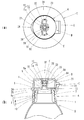
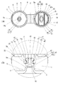
図1において、Aは容器Dに装着されるキャップ本体、Bはキャップ本体Aにヒンジ部Cを介して開閉可能に取り付けられる上蓋である。
容器Dは、口部1を有する容器であり、口部1の外周面には、雄ねじ部2が設けられている。
In FIG. 1, A is a cap main body attached to the container D, and B is an upper lid attached to the cap main body A via a hinge part C so as to be opened and closed.
The container D is a container having a mouth portion 1, and a
キャップ本体Aは、図1、2に示すように、容器Dの口部1に装着される装着部3と、装着部3から内方に延設され口部1の開口を封鎖する上壁4と、上壁4を貫通する注出口の周囲から立設される注出部としてのノズル5とを備えている。
As shown in FIGS. 1 and 2, the cap body A includes a
装着部3は、上蓋Bと係合する上蓋係合部6が周設される基壁7と、基壁7の内周縁から下面に垂設され、外周が容器Dの口部1内周に挿入される内筒8と、基壁7の外周縁から垂設される外筒9とから構成されている。
外筒9には、外周上端部のヒンジ部Cと反対側に後述する上蓋Bの把手部24と対向する位置に切欠凹部9aが形成され、内周に容器Dの口部1の雄ねじ部2と螺合する雌ねじ部10が設けられている。
The
A
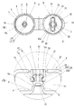
ノズル5の先端部5aは、内方に縮径されるとともに、ノズル5の先端部5aには、破断可能な薄肉部11を介して、もぎり栓12が形成されている。
もぎり栓12は、図2に示すように、ノズル5の先端部5aから連続するノズル孔13と、ノズル孔13を包囲して立設される栓本体14と、栓本体14の外周の平面視でヒンジ部Cの反対側を0°として90°と270°の箇所に突設される回転止め突部15とから構成されている。
栓本体14の外周には、上端部に上が細く傾斜するテーパー面14aが設けられ、中程に回転止め突部15を除いて凹設される掛止凹部16が配設されている。
The
As shown in FIG. 2, the
On the outer periphery of the
上蓋Bは、図1、2に示すように、頂壁20と、頂壁20の外縁から垂設され、外周にヒンジ部Cを介してキャップ本体Aに連設される側周壁21と、頂壁20の中央に開口部22が穿設されるとともに、その内方に、閉蓋時にキャップ本体Aのもぎり栓12を内方に掛止する摘み部材Eが連設され、キャップ本体Aに対して開閉自在に取着されている。
As shown in FIGS. 1 and 2, the upper lid B is provided with a
頂壁20の開口部22は、摘み部材Eの平面視の形に合わせて形成されるとともに、摘み部材Eとの間に僅かな空間を形成し、摘み部材Eと頂壁20の開口部22の内方は、複数(本実施例では、ヒンジ部C側を起点として90°間隔で4箇所)配設された破断可能な破断ブリッジ23を介して連設されている。
The
側周壁21は、外周の片側にヒンジ部Cが連設され、外周下端部のヒンジ部Cと反対側に、平面視で円弧状の把手部24が設けられ、内周下端部に、キャップ本体Aの上蓋係合部6と係合して閉蓋状態を維持させる基壁係合部25が設けられている。
The side
摘み部材Eは、図1、2に示すように、閉蓋時にキャップ本体Aのもぎり栓12を内方に掛止する中央の係合筒部30と、係合筒部30の外周から平面視でヒンジ部Cの反対側を0°として90°と270°の箇所に張り出すように突設される摘み部31とから構成され、両方の摘み部31の先端部上端および係合筒部30の外周の両側上端に破断ブリッジ23が連設されている。
As shown in FIGS. 1 and 2, the knob member E is a plan view from the outer periphery of the
係合筒部30には、内周の両方の摘み部31側に、摘み部31の根本付近まで延び、閉蓋時にキャップ本体Aのもぎり栓12の回転止め突部15の先端部が嵌入する回転止め溝32が凹設され、内周下端部には、回転止め溝32を除いて、キャップ本体Aのもぎり栓12の掛止凹部16に嵌入する掛止突部33が突設されている。
掛止突部33は、上部のほぼ水平に内方に延びる水平面33aと、水平面33aの先端から外方に向かうとともに係合筒部30の下端に延びる傾斜面33bとから形成されている。
The engaging
The latching
次に、本実施例の使用態様と作用効果について図面を参照しながら説明する。
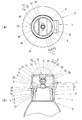
本実施例のキャップは、図2(a)に示すように、上蓋Bが完全に開いた状態でヒンジ部Cを介してキャップ本体Aと一体成形により製造される。
Next, usage modes and operational effects of the present embodiment will be described with reference to the drawings.
As shown in FIG. 2A, the cap of this embodiment is manufactured by integral molding with the cap main body A via the hinge portion C in a state where the upper lid B is completely opened.
次に、開いた状態から図1に示すように上蓋Bを閉じてキャップをセットする際には、上蓋Bの把手部24を持ってヒンジ部Cを中心に回動させると、摘み部材Eの係合筒部30の内周に設けられた回転止め溝32の内方にキャップ本体Aのもぎり栓12の回転止め突部15が挿入されていくとともに、係合筒部30の内周下端部に設けられた掛止突部33の傾斜面33bがもぎり栓12の上端のテーパー面14aに当接し、互いの傾斜により、係合筒部30下部を僅かに変形させながら、乗り越えていく。
この場合には、摘み部材Eが上蓋Bから分離されないように、破断ブリッジ23の破断強度は、係合筒部30の乗り越え抵抗よりも大きくなるように設定されている。
また、係合筒部30の掛止突部33に傾斜面33bを設け、もぎり栓12の上端にテーパー面14aを設けており、互いに楽に乗り越えていくようになっているので、係合筒部30の乗り越え抵抗は、さほど大きくする必要はない。
Next, when the upper lid B is closed and the cap is set as shown in FIG. 1 from the opened state, if the
In this case, the breaking strength of the breaking
In addition, the latching
また、上蓋Bを閉じる際に、破断ブリッジ23が破断しないように、上蓋Bの頂壁20の上面と摘み部材Eの上面(すなわち、上蓋Bの天面全体)を押さえて、上蓋Bを閉蓋することもできる。
この場合には、破断ブリッジ23の破断強度は、係合筒部30の乗り越え抵抗よりも小さく設定することが可能である。
Further, when the upper lid B is closed, the upper surface of the
In this case, the breaking strength of the breaking
最後は、図1、2(b)に示すように、係合筒部30の掛止突部33の先端がもぎり栓12の掛止凹部16に嵌入して掛止され、さらに、キャップ本体Aの上蓋係合部6は、上蓋Bの側周壁21の基壁係合部25と係合し、未開封状態として閉じられる。
本実施例のもぎり栓付きキャップは、成形後、上蓋Bを閉じることにより、もぎり栓12を摘み部材Eおよび上蓋B内で保護しているので、納品の際に、バラ詰めでも、もぎり栓12が折れたりするのを防止できる。
Finally, as shown in FIGS. 1 and 2B, the tip of the latching
In the cap with a mortar plug of this embodiment, the
次に、上蓋Bが閉じた状態のキャップを内容液が充填された容器Dの口部1に装着される。
装着工程は、キャップ本体Aの装着部3を容器Dの口部1に当てがい、キャップを回転することで、口部1の雄ねじ部2とキャップ本体Aの装着部3の外筒9の雌ねじ部10を螺合させ、装着される。
なお、本実施例では、容器Dの口部1の雄ねじ部2とキャップ本体Aの外筒9の雌ねじ部10を螺合させことで、キャップを容器Dに装着しているが、必ずしもこのような手段に限らず、口部1と外筒9にそれぞれ係合する突部を設け、キャップを打栓して装着させるなどの他の手段によって装着してもよい。
Next, the cap with the upper lid B closed is attached to the mouth 1 of the container D filled with the content liquid.
In the mounting step, the mounting
In this embodiment, the cap is mounted on the container D by screwing the male threaded
本実施例のもぎり栓付きキャップが装着された容器においては、キャップ本体Aのもぎり栓12を摘み部材Eに装着し、摘み部材Eの側面を上蓋Bの頂壁20開口部22の内方および側周壁21により保護しているので、流通時に、もぎり栓12が外力を受けてキャップ本体Aのノズル5に対して折れ曲がったり、破断したりするのを防止することができる。
In the container equipped with the cap with a throat plug of the present embodiment, the
容器D内の内容液を使用するにあたり、キャップを最初に開ける際には、図1に示すキャップ本体Aの外筒9の切欠凹部9aから上蓋Bの把手部24の下面に手指を掛けて持ち上げ、キャップ本体Aの上蓋係合部6と上蓋Bの基壁係合部25との係合を解除し、ヒンジ部Cを中心に上蓋Bを回動させていく。
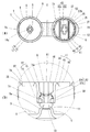
すると、摘み部材Eも上蓋Bと一緒に持ち上がろうとするが、摘み部材Eの係合筒部30の掛止突部33の水平面33aが、もぎり栓12の掛止凹部16に掛止されており、破断ブリッジ23の破断強度は、係合筒部30の引き上げ抵抗よりも小さく設定されているので、破断ブリッジ23は、ヒンジ部Cと反対側方向から順に破断し、最後に、ヒンジ部C側の破断ブリッジ23も破断され、摘み部材Eを上蓋Bの開口部22から完全に切り離すと、図3に示すように、摘み部材Eは、もぎり栓12の上面に移行した状態になって開蓋される。
なお、破断ブリッジ23の破断強度は、もぎり栓12の薄肉部11の破断強度よりも小さく設定されているのは、当然のことである。
When using the content liquid in the container D, when opening the cap for the first time, lift the finger from the notched
Then, although the knob member E also tries to be lifted together with the upper lid B, the
Of course, the breaking strength of the breaking
本実施例のキャップは、未開封状態では、上蓋Bの摘み部材Eの係合筒部30が、もぎり栓12の掛止凹部16に掛止されているので、未開封状態から、無理に上蓋Bを開閉すると、上蓋Bの頂壁20の開口部22と摘み部材Eとを連設する破断ブリッジ23が破断され、上蓋Bを再度閉じても、摘み部材Eと上蓋Bの頂壁20の開口部22との破断ブリッジ23が破断しているので、不正に開閉したことが簡単に視認できる。
When the cap of the present embodiment is not opened, the engaging
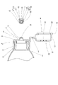
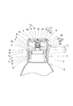
次に、図3に示す状態から、摘み部材Eの摘み部31の両方または片方に指を掛けて捻ることにより、摘み部材Eの回転とともに、摘み部材Eの係合筒部30の回転止め溝32内に嵌入したキャップ本体Aのもぎり栓12の回転止め突部15との係合により、もぎり栓12もノズル5に対して捻られ、薄肉部11が破断し、もぎり栓12をノズル5から取り除き、図4に示すように、ノズル5の先端部5aにノズル孔13を開口し、ノズル5を開封する。
キャップ本体Aのノズル5が開封されることにより、図5に示すように、容器Dを傾けただけで、容易にノズル5から容器D内の内容液を注出することができる。
Next, from the state shown in FIG. 3, the rotation stop groove of the
By opening the
本実施例のキャップは、基本的には、内容液を1回で使い切る容器用であるから、容器Dから内容液を注出した後は、そのまま、廃棄する。
また、もぎり栓12を捻り取ってノズル5のノズル孔13の開口した後は、再び、閉鎖することは出来ず、さらに、上蓋Bの頂壁20の開口部22の空間が開いているので、視認して開蓋が確認でき、容器の使用状況を確実に知ることが出来る。
容器Dは、傾けて内容液をノズル5から注出するものに限らず、容器Dをスクイズしてノズル5から内容液を注出するものであっても構わない。
Since the cap of the present embodiment is basically for a container where the content liquid is used up once, after the content liquid is poured out from the container D, it is discarded as it is.
In addition, after twisting off the
The container D is not limited to the one that tilts and discharges the content liquid from the
本実施例では、もぎり栓12に、栓本体14の外周の平面視でヒンジ部Cの反対側を0°として90°と270°の箇所に回転止め突部15を突設し、それに合わせて、摘み部材Eに、90°と270°の箇所に摘み部31と、回転止め溝32を設けたが、閉蓋時に、回転止め突部15が回転止め溝32に挿入して係合し、開蓋後に、その係合により、摘み部31に指を掛けて摘み部材Eを捻ることで、もぎり栓12を捻り取ることができればよいので、回転止め突部15の配設箇所および数はどのようなものでもよく、また、回転止め溝32は、回転止め突部15の配設箇所および数に合わせて配設すればよく、またさらに、摘み部31の配設箇所および数も指を掛け、摘み部材Eを捻り取ることができればよいので、配設箇所および数はどのようなものでもよい。
もぎり栓の回転止め突部、摘み部材の摘み部および回転止め溝の配設箇所および数は上記実施例の形態に限定されない。
In this embodiment,
The location and number of the rotation stop protrusions of the mortar plugs, the knob portions of the knob members, and the rotation stop grooves are not limited to the above-described embodiment.
次に、上記第1実施例の上蓋Bおよび摘み部材Eの形状を変更した第2実施例について、図を参照して説明する。
以下、第1実施例と同一の構成部分には同一の符号を付し、栓体の変更部分に新たな符号を付し、相違点を中心に説明する。
Next, a second embodiment in which the shapes of the upper lid B and the knob member E of the first embodiment are changed will be described with reference to the drawings.
In the following, the same components as those in the first embodiment are denoted by the same reference numerals, and the changed portions of the plug body are denoted by new symbols, and the differences will be mainly described.
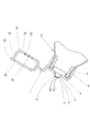
図6において、Aは容器Dに装着されるキャップ本体、Baはキャップ本体Aにヒンジ部Cを介して開閉可能に取り付けられる上蓋である。 In FIG. 6, A is a cap body mounted on the container D, and Ba is an upper lid attached to the cap body A via a hinge portion C so as to be opened and closed.
上蓋Baは、図6、7に示すように、外周にヒンジ部Cを介してキャップ本体Aに連設される側周壁35と、側周壁35の内周上端を開口部36とし、開口部36の内方に、複数(本実施例では、ヒンジ部C側を起点として90°間隔で4箇所)配設された破断可能な破断ブリッジ37を介して連設される摘み部材Fとからなっている。
As shown in FIGS. 6 and 7, the upper lid Ba has a side
側周壁35は、外周の片側にヒンジ部Cが連設され、外周下端部のヒンジ部Cと反対側に、把手部24が設けられ、内周下端部に、基壁係合部25が設けられている。
The side
摘み部材Fは、外縁が開口部36との間に僅かな空間を形成するとともに、中央にキャップ本体Aのもぎり栓12の平面視の形に穿設された係合孔40を設けたリング状の上板41と、上板41の係合孔40の縁から垂設される係合筒部42とからなっている。
The knob member F has a ring shape in which an outer edge forms a slight space between the
係合孔40は、もぎり栓12の栓本体14の外周形状に形成される中央部40aと、中央部40aからもぎり栓12の両方の回転止め突部15の形状に形成される回転止め部40bとからなっている。
The
上板41は、下面に、係合筒部42の外縁に近接してヒンジ部C側とその反対側の両側に位置し、回転止め部40bと平行に延びる折曲溝43が凹設され、折曲溝43により、中央の基板部44と、その両側のD形状に形成された摘み板部45に区画されている。
On the lower surface of the
係合筒部42は、内周に、回転止め部40bの内周から下端まで延びる回転止め溝46が形成され、内周下端部には、回転止め溝46を除いて、キャップ本体Aのもぎり栓12の掛止凹部16に嵌入する掛止突部47が突設されている。
掛止突部47は、上部のほぼ水平に内方に延びる水平面47aと、水平面47aの先端から外方に向かうとともに係合筒部42の下端に延びる傾斜面47bとから形成されている。
The
The latching
次に、本実施例の使用態様と作用効果について図面を参照しながら説明する。
上蓋Baを閉じてキャップをセットする際には、上蓋Baの把手部24を持ってヒンジ部Cを中心に回動させると、摘み部材Fの係合筒部42に設けられた回転止め溝46の内方にキャップ本体Aのもぎり栓12の回転止め突部15が挿入されていくとともに、係合筒部42の内周下端部に設けられた掛止突部47の傾斜面47bがもぎり栓12の上端のテーパー面14aに当接し、互いの傾斜により、係合筒部42下部を僅かに変形させながら、乗り越えていく。
この場合には、摘み部材Fが上蓋Baから分離されないように、破断ブリッジ37の破断強度は、係合筒部42の乗り越え抵抗よりも大きくなるように設定されている。
また、係合筒部42の掛止突部47に傾斜面47bを設け、もぎり栓12の上端にテーパー面14aを設けており、互いに楽に乗り越えていくようになっているので、係合筒部42の乗り越え抵抗は、さほど大きくする必要はない。
当然、上蓋Baを閉じる際に、破断ブリッジ37が破断しないように、上蓋Baの側周壁35の上端面と摘み部材Fの上面(すなわち、上蓋Baの天面全体)を押さえて、上蓋Baを閉蓋するようにしてもよい。
Next, usage modes and operational effects of the present embodiment will be described with reference to the drawings.
When closing the top cover Ba and setting the cap, if the
In this case, the breaking strength of the breaking
In addition, the latching
Naturally, when closing the upper lid Ba, the upper lid Ba is pressed against the upper end surface of the side
最後は、図6に示すように、係合筒部42の掛止突部47の先端がもぎり栓12の掛止凹部16に嵌入して掛止され、さらに、キャップ本体Aの上蓋係合部6は、上蓋Baの側周壁35の基壁係合部25と係合し、未開封状態として閉じられる。
本実施例のもぎり栓付きキャップは、成形後、上蓋Baを閉じることにより、もぎり栓12を摘み部材Fおよび上蓋Ba内で保護しているので、納品の際に、バラ詰めでも、もぎり栓12が折れたりするのを防止できる。
また、もぎり栓付きキャップが装着された容器においても、もぎり栓12を摘み部材Fおよび上蓋Ba内で保護しているので、流通時に、もぎり栓12が外力を受けてキャップ本体Aのノズル5に対して折れ曲がったり、破断したりするのを防止することができる。
Finally, as shown in FIG. 6, the tip of the latching
In the cap with a mortar plug of the present embodiment, the
Further, even in a container equipped with a cap with a mortar plug, since the
容器D内の内容液を使用するにあたり、キャップを最初に開ける際には、キャップ本体Aに対して、ヒンジ部Cを中心に上蓋Baを回動させていく。
すると、摘み部材Fも上蓋Baと一緒に持ち上がろうとするが、摘み部材Fの係合筒部42の掛止突部47の水平面47aが、もぎり栓12の掛止凹部16に掛止されており、破断ブリッジ37は、ヒンジ部Cと反対側方向から順に破断され、摘み部材Fを上蓋Baの開口部36から完全に切り離すと、図8に示すように、摘み部材Fは、もぎり栓12の上面に移行した状態になって開蓋される。
なお、破断ブリッジ37の破断強度は、もぎり栓12の薄肉部11の破断強度よりも小さく設定されているのは、当然のことである。
In using the content liquid in the container D, when opening the cap for the first time, the upper lid Ba is rotated with respect to the cap body A around the hinge portion C.
Then, the knob member F tries to be lifted together with the upper lid Ba, but the
Of course, the breaking strength of the breaking
本実施例のキャップは、未開封状態では、上蓋Baの摘み部材Fの係合筒部42が、もぎり栓12の掛止凹部16に掛止されているので、未開封状態から、無理に上蓋Baを開閉すると、上蓋Baの側周壁35の開口部36と摘み部材Fとを連設する破断ブリッジ37が破断され、上蓋Baを再度閉じても、摘み部材Fと上蓋Baの開口部36との破断ブリッジ37が破断しているので、不正に開閉したことが簡単に視認できる。
When the cap of the present embodiment is not opened, the engaging
次に、図9に示すように、摘み部材Fの上板41の両方の摘み板部45を折曲溝43で基板部44に対して上方に折り曲げる。
そして、両方の摘み板部45の外側面を摘むように指を掛けて捻ることにより、摘み部材Fの回転とともに、摘み部材Fの係合筒部42の回転止め溝46内に嵌入したキャップ本体Aのもぎり栓12の回転止め突部15との係合により、もぎり栓12もノズル5に対して捻られ、薄肉部11が破断し、もぎり栓12を摘み部材Fとともにノズル5から取り除き、ノズル5の先端部5aにノズル孔13を開口し、ノズル5を開封し、容器D内の内容液を使用する。
本実施例では、摘み部材Fの両方の摘み板部45を折曲溝43で基板部44に対して上方に折り曲げているが、別に摘み板部45を下方に折り曲げ、両方の摘み板部45の外側面を摘むように指を掛けて捻るようにしてもよい。
Next, as shown in FIG. 9, both the
Then, the cap main body A fitted into the rotation stop
In the present embodiment, both of the
ノズル5のノズル孔13の開口した後は、再び、閉鎖することは出来ず、さらに、上蓋Baの開口部36の空間が開いているので、視認して開蓋が確認でき、容器の使用状況を確実に知ることが出来る。
その他の構成の作用効果については、第1実施例と同様である。
After the
About the effect of other composition, it is the same as that of the 1st example.
次に、上記第2実施例の摘み部材Fの形状を変更した第3実施例について、図を参照して説明する。
以下、第2実施例と同一の構成部分には同一の符号を付し、栓体の変更部分に新たな符号を付し、相違点を中心に説明する。
Next, a third embodiment in which the shape of the knob member F of the second embodiment is changed will be described with reference to the drawings.
In the following, the same components as those in the second embodiment are denoted by the same reference numerals, and the changed portions of the plug body are denoted by new symbols, and the differences will be mainly described.
図10において、Aは容器Dに装着されるキャップ本体、Bbはキャップ本体Aにヒンジ部Cを介して開閉可能に取り付けられる上蓋である。 In FIG. 10, A is a cap main body mounted on the container D, and Bb is an upper lid attached to the cap main body A via a hinge portion C so as to be opened and closed.
上蓋Bbは、図10、11に示すように、外周にヒンジ部Cを介してキャップ本体Aに連設される側周壁35と、側周壁35の内周上端を開口部36とし、開口部36の内方に、複数(本実施例では、ヒンジ部C側を起点として90°間隔で4箇所)配設された破断可能な破断ブリッジ37を介して連設される摘み部材Gとからなっている。
As shown in FIGS. 10 and 11, the upper lid Bb has a side
摘み部材Gは、外縁が開口部36との間に僅かな空間を形成するとともに、中央にキャップ本体Aのもぎり栓12の平面視の形に穿設された係合孔40を設けたリング状の上板41と、上板41の係合孔40の縁から垂設され、閉蓋時に下部にキャップ本体Aのもぎり栓12が挿入される係合筒部50とからなっている。
The knob member G has a ring-like shape in which the outer edge forms a slight space between the
係合筒部50は、内周に回転止め部40bから下端まで延びる回転止め溝51が形成され、内周のほぼ中間には、回転止め溝51を除いて、キャップ本体Aのもぎり栓12の掛止凹部16に嵌入する掛止突部52が突設されている。
掛止突部52は、上部のほぼ水平に内方に延びる水平面52aと、水平面52aの先端から外方に向かうとともに下方に延びる傾斜面52bとから形成されている。
The
The latching
次に、本実施例の使用態様と作用効果について図面を参照しながら説明する。
上蓋Bbを閉じてキャップをセットする際には、上蓋Bbの把手部24を持ってヒンジ部Cを中心に回動させると、摘み部材Gの係合筒部50に設けられた回転止め溝51の内方にキャップ本体Aのもぎり栓12の回転止め突部15が挿入されていくとともに、係合筒部50の内周下部にもぎり栓12の栓本体14が挿入されていく。
Next, usage modes and operational effects of the present embodiment will be described with reference to the drawings.
When closing the top lid Bb and setting the cap, if the
最後は、図10に示すように、摘み部材Gの下部にキャップ本体Aのもぎり栓12が挿入されるとともに、上蓋Bbの側周壁35の基壁係合部25がキャップ本体Aの上蓋係合部6と係合し、未開封状態として上蓋Bbが閉じられる。
本実施例のもぎり栓付きキャップは、成形後、上蓋Bbを閉じることにより、もぎり栓12を摘み部材Gおよび上蓋Bb内で保護しているので、納品の際に、バラ詰めでも、もぎり栓12が折れたりするのを防止できる。
また、もぎり栓付きキャップが装着された容器においても、もぎり栓12を摘み部材Gのおよび上蓋Bb内で保護しているので、流通時に、もぎり栓12が外力を受けてキャップ本体Aのノズル5に対して折れ曲がったり、破断したりするのを防止することができる。
Finally, as shown in FIG. 10, the
In the cap with a mortar plug of this embodiment, the
Further, even in a container equipped with a cap with a mortar plug, the
容器D内の内容液を使用するにあたり、まず、摘み部材Gの上板41上方から押し込み、上蓋Bbの開口部36と連設する破断ブリッジ37を破断させ、上蓋Bbおよびキャップ本体Aに対して摘み部材Gを下降させていく。
すると、摘み部材Gの係合筒部50がキャップ本体Aのもぎり栓12に対し下降していき、係合筒部50の内周に設けられた掛止突部52の傾斜面52bがもぎり栓12の上端のテーパー面14aに当接し、互いの傾斜により、係合筒部50下部を僅かに変形させながら、乗り越えていく。
この場合には、傾斜面52bとテーパー面14aにより互いに楽に乗り越えていくようになっているので、係合筒部50の乗り越え抵抗は、さほど大きくする必要はない。
In using the content liquid in the container D, first, the
Then, the engaging
In this case, since the
最後は、図12に示すように、掛止突部52の先端がもぎり栓12の掛止凹部16に嵌入して掛止されるとともに、乗り越えたことによるクリック感により、使用者に下降を終了することを知らせる。
Finally, as shown in FIG. 12, the tip of the latching
次に、上蓋Bbをキャップ本体Aからヒンジ部Cを介して開蓋した後、図13に示すように、摘み部材Gの上板41の両方の摘み板部45を折曲溝43で基板部44に対して上方に折り曲げる。
そして、両方の摘み板部45の外側面を摘むように指を掛けて捻ることにより、摘み部材Gの回転とともに、摘み部材Gの係合筒部50の回転止め溝51内に嵌入したキャップ本体Aのもぎり栓12の回転止め突部15との係合により、もぎり栓12もノズル5に対して捻られ、薄肉部11が破断し、さらに、もぎり栓12の掛止凹部16と係合筒部50の掛止突部52との掛止により、もぎり栓12を摘み部材Gと一緒にノズル5から取り除き、ノズル5の先端部5aにノズル孔13を開口し、ノズル5を開封し、容器D内の内容液を使用する。
Next, after the upper lid Bb is opened from the cap body A via the hinge portion C, both the
And the cap main body A inserted into the rotation stop
ノズル5のノズル孔13の開口した後は、再び、閉鎖することは出来ず、さらに、上蓋Bbの開口部36の空間が開いているので、視認して開蓋が確認でき、容器の使用状況を確実に知ることが出来る。
その他の構成の作用効果については、第2実施例と同様である。
After the
About the effect of other composition, it is the same as that of the 2nd example.
次に、上記第1〜3実施例のキャップ本体および上蓋を連設するヒンジ部を省いた第4実施例について、第3実施例を元にして図を参照して説明する。
以下、第3実施例と同一の構成部分には同一の符号を付し、栓体の変更部分に新たな符号を付し、相違点を中心に説明する。
Next, a description will be given of a fourth embodiment in which the cap body of the first to third embodiments and the hinge portion connecting the upper lid are omitted with reference to the drawings based on the third embodiment.
Hereinafter, the same components as those in the third embodiment will be denoted by the same reference numerals, and the changed portions of the plug body will be denoted by new reference numerals, and differences will be mainly described.
図14において、Aaは容器Dに装着されるキャップ本体、Hはキャップ本体Aaに開閉可能に取り付けられる上蓋である。 In FIG. 14, Aa is a cap body attached to the container D, and H is an upper lid attached to the cap body Aa so as to be opened and closed.
キャップ本体Aaは、図14に示すように、容器Dの口部1に装着される装着部3と、装着部3から内方に延設され口部1の開口を封鎖する上壁4と、上壁4を貫通する注出口の周囲から立設される注出部としてのノズル5とを備えている。
装着部3は、上蓋Hと係合する上蓋係合部6が周設される基壁7と、基壁7の内周縁から下面に垂設され、外周が容器Dの口部1内周に挿入される内筒8と、基壁7の外周縁から垂設される外筒9とから構成されている。
As shown in FIG. 14, the cap main body Aa includes a mounting
The mounting
ノズル5の先端部5aの先端部5aには、破断可能な薄肉部11を介して、もぎり栓12が形成されている。
もぎり栓12は、栓本体14と、栓本体14の両側に突設される回転止め突部15とが構成されている。
At the
The mortar plug 12 includes a
上蓋Hは、側周壁55と、側周壁55の内周上端を開口部36とし、開口部36の内方に、複数(本実施例では、90°間隔で4箇所)配設された破断可能な破断ブリッジ37を介して連設される摘み部材Gとからなっている。
The upper lid H has a side
側周壁55は、内周下端部に、閉蓋時にキャップ本体Aaの上蓋係合部6と係合する基壁係合部25が設けられている。
The side
摘み部材Gの係合筒部50には、閉蓋時にキャップ本体Aaのもぎり栓12の回転止め突部15が挿入される位置に合わせて回転止め溝51が形成されている。
The
次に、本実施例の使用態様と作用効果について図面を参照しながら説明する。
上蓋Hを閉じてキャップをセットする際には、キャップ本体Aaのもぎり栓12の回転止め突部15と上蓋Hの摘み部材Gの係合筒部50の回転止め溝部51とを位置合わせして、キャップ本体Aaに上蓋Hを被せていく。
Next, usage modes and operational effects of the present embodiment will be described with reference to the drawings.
When closing the top lid H and setting the cap, the rotation stop
最後は、摘み部材Gの下部にキャップ本体Aaのもぎり栓12が挿入されるとともに、上蓋Hの側周壁55の基壁係合部25がキャップ本体Aaの上蓋係合部6と係合し、未開封状態として上蓋Hが閉じられる。
本実施例のもぎり栓付きキャップは、上蓋Hを閉じることにより、もぎり栓12を摘み部材Gおよび上蓋H内で保護しているので、納品の際に、バラ詰めでも、もぎり栓12が折れたりするのを防止できる。
また、もぎり栓付きキャップが装着された容器においても、もぎり栓12を摘み部材Gのおよび上蓋H内で保護しているので、流通時に、もぎり栓12が外力を受けてキャップ本体Aaのノズル5に対して折れ曲がったり、破断したりするのを防止することができる。
Finally, the
The cap with a mortar plug of the present embodiment protects the mortar plug 12 within the knob member G and the upper lid H by closing the upper lid H. Can be prevented.
Further, even in a container equipped with a cap with a mortar plug, since the
容器D内の内容液を使用するにあたり、まず、摘み部材Gの上板41上方から押し込み、上蓋Hの開口部36と連設する破断ブリッジ37を破断させ、上蓋Hおよびキャップ本体Aaに対して摘み部材Gを下降させ、摘み部材Gをキャップ本体Aaのもぎり栓12に嵌合させる。
In using the content liquid in the container D, first, the
次に、上蓋Hをキャップ本体Aaから外した後、図15に示すように、摘み部材Gの上板41の両方の摘み板部45を折曲溝43で基板部44に対して上方に折り曲げ、摘み板部45の外側面を摘み、捻ることにより、もぎり栓12もノズル5に対して捻り切られ、もぎり栓12を摘み部材Gと一緒に取り除き、ノズル5を開封し、容器D内の内容液を使用する。
Next, after removing the upper lid H from the cap main body Aa, as shown in FIG. 15, both the
ノズル5のノズル孔13の開口した後は、再び、閉鎖することは出来ず、さらに、上蓋Hの開口部36の空間が開いているので、視認して開蓋が確認でき、容器の使用状況を確実に知ることが出来る。
その他の構成の作用効果については、第3実施例と同様である。
また、本実施例では第3実施例を元に説明したが、第1実施例および第2実施例のキャップ本体と上蓋とを一体化するヒンジ部を省いて、キャップ本体と上蓋とを別体としてもよい。
After the
About the effect of other structures, it is the same as that of 3rd Example.
Further, in the present embodiment, the description has been given based on the third embodiment, but the cap body and the upper lid of the first and second embodiments are omitted, and the cap body and the upper lid are separated. It is good.
本発明のもぎり栓付きキャップは、上蓋を閉めることによりもぎり栓を保護することができるので、もぎり栓が不用意に折れるのを防止することができ、また、最初の開蓋時の操作で、もぎり栓に装着される摘み部材が摘みを形成するので、もぎり栓を捻り取り易くすることができ、とくに、1回使い切りで使用する内容液が充填された容器のもぎり栓付きキャップとして好適である。 Since the cap with a mortar plug of the present invention can protect the worm plug by closing the upper lid, it can prevent the mortar plug from being accidentally broken, and in the operation at the first opening of the lid, Since the knob member attached to the mortar plug forms a knob, the mortar plug can be easily twisted, and is particularly suitable as a cap with a mortar plug for a container filled with the content liquid to be used once. .
A、Aa キャップ本体
B、Ba、Bb、H 上蓋
C ヒンジ部
D 容器
E、F、G 摘み部材
1 口部
2 雄ねじ部
3 装着部
4 上壁
5 ノズル(注出部)
5a 先端部
6 上蓋係合部
7 基壁
8 内筒
9 外筒
9a 切欠凹部
10 雌ねじ部
11 薄肉部
12 もぎり栓
13 ノズル孔
14 栓本体
14a テーパー面
15 回転止め突部
16 掛止凹部
20 頂壁
21、35、55 側周壁
22、36 開口部
23、37 破断ブリッジ
24 把手部
25 基壁係合部
30、42、50 係合筒部
31 摘み部
32、46、51 回転止め溝
33、47、52 掛止突部
33a、47a、52a 水平面
33b、47b、52b 傾斜面
40 係合孔
40a 中央部
40b 回転止め部
41 上板
43 折曲溝
44 基板部
45 摘み板部
A, Aa Cap body B, Ba, Bb, H Upper lid C Hinge part D Container E, F, G Knob member 1
32, 46, 51
Claims (9)
キャップ本体は、容器の口部に装着される装着部と、装着部内縁から内方に延設され口部の開口を封鎖する上壁と、上壁を貫通して形成される注出部と、注出部の先端部に破断可能に連設されるもぎり栓とを備え、
上蓋は、閉蓋時に、もぎり栓の上部に破断可能に設けられる摘み部材を備え、
摘み部材は、もぎり栓を覆い、掛止する係合筒部を備えることを特徴とするもぎり栓付きキャップ。 A cap with a throat plug, comprising a cap body whose pouring portion is sealed by a mortar plug, and an upper lid that is openably and closably attached to the cap body,
The cap body includes a mounting portion attached to the mouth portion of the container, an upper wall extending inwardly from the inner edge of the mounting portion and sealing the opening of the mouth portion, and a pouring portion formed through the upper wall. , Provided with a mortar plug that is continuously connected to the tip of the pouring part so as to be breakable,
The upper lid is provided with a knob member that can be broken at the upper part of the mug stopper when the lid is closed,
A knob with a mortar plug, wherein the knob member includes an engagement tube portion that covers and hooks the mortar plug.
摘み部材の係合筒部は、内周を上下方向に延びる回転止め溝と、内周に回転止め溝を除いて突設される掛止突部とを有することを特徴とする請求項1に記載のもぎり栓付きキャップ。 The plug is provided with a stopper main body that seals the pouring part, a latching recess provided around the outer periphery of the stopper main body, and a rotation stopping protrusion protruding from the outer periphery of the stopper main body.
The engaging cylinder portion of the knob member has a rotation stop groove extending in the vertical direction on the inner periphery and a latching protrusion protruding from the inner periphery excluding the rotation stop groove. The cap with the above-mentioned mug plug.
摘み部材は、頂壁に形成される開口部と、該開口部の内方に破断可能な破断ブリッジを介して連設されることを特徴とする請求項1〜4のいずれかに記載のもぎり栓付きキャップ。 The upper lid includes a top wall and a side peripheral wall that is suspended from the outer edge of the top wall,
The picking member is provided continuously through an opening formed in the top wall and a breakable bridge that can be broken inwardly of the opening. Cap with stopper.
摘み部材は、側周壁の内周上端に、破断可能な複数の破断ブリッジを介して連設されることを特徴とする請求項1〜4のいずれかに記載のもぎり栓付きキャップ。 The upper lid includes a side peripheral wall whose lower end is attached to the cap body,
The knob with caps according to any one of claims 1 to 4, wherein the knob member is connected to the upper end of the inner periphery of the side peripheral wall via a plurality of breakable breakable bridges.
上壁は、係合筒部を挟んで平行して延びる2本の折曲溝と、折曲溝により区画される中央の基板部と、基板部の両側にD形状に形成される摘み板部とを有することを特徴とする請求項1〜6のいずれかに記載のもぎり栓付きキャップ。 The knob member includes a ring-shaped upper wall in which an engagement hole is formed in the center according to the planar shape of the serrated plug, and an engagement cylinder portion that is suspended from the engagement hole edge of the upper wall.
The upper wall includes two bent grooves extending in parallel with the engaging cylinder portion interposed therebetween, a central substrate portion defined by the bent grooves, and a grip plate portion formed in a D shape on both sides of the substrate portion The cap with a mortar plug according to any one of claims 1 to 6.
Priority Applications (1)
| Application Number | Priority Date | Filing Date | Title |
|---|---|---|---|
| JP2016068953A JP6552447B2 (en) | 2016-03-30 | 2016-03-30 | Mole cap with cap |
Applications Claiming Priority (1)
| Application Number | Priority Date | Filing Date | Title |
|---|---|---|---|
| JP2016068953A JP6552447B2 (en) | 2016-03-30 | 2016-03-30 | Mole cap with cap |
Publications (2)
| Publication Number | Publication Date |
|---|---|
| JP2017178376A true JP2017178376A (en) | 2017-10-05 |
| JP6552447B2 JP6552447B2 (en) | 2019-07-31 |
Family
ID=60003558
Family Applications (1)
| Application Number | Title | Priority Date | Filing Date |
|---|---|---|---|
| JP2016068953A Expired - Fee Related JP6552447B2 (en) | 2016-03-30 | 2016-03-30 | Mole cap with cap |
Country Status (1)
| Country | Link |
|---|---|
| JP (1) | JP6552447B2 (en) |
Cited By (6)
| Publication number | Priority date | Publication date | Assignee | Title |
|---|---|---|---|---|
| PL127007U1 (en) * | 2018-02-08 | 2019-08-12 | Kałczyńska Teresa Pphu Jatex | A nut with a plug |
| JP2020001797A (en) * | 2018-06-29 | 2020-01-09 | 株式会社吉野工業所 | Extraction cap |
| JP2020183237A (en) * | 2019-04-26 | 2020-11-12 | 株式会社吉野工業所 | cap |
| JP2021160789A (en) * | 2020-03-31 | 2021-10-11 | 株式会社吉野工業所 | Container cap and method for manufacturing container cap |
| CN115649634A (en) * | 2022-11-17 | 2023-01-31 | 米建军 | Bottle cap |
| JP2024055986A (en) * | 2020-04-30 | 2024-04-19 | 株式会社吉野工業所 | Manufacturing method for container cap |
Citations (4)
| Publication number | Priority date | Publication date | Assignee | Title |
|---|---|---|---|---|
| US20040011697A1 (en) * | 2002-07-16 | 2004-01-22 | Lameplast S.P.A. | Container for packaging fluid or pasty products, particularly cosmetic products, medicinal products, and the like |
| JP2010208698A (en) * | 2010-05-27 | 2010-09-24 | Toyo Seikan Kaisha Ltd | Injection device for fluid container |
| JP2012136274A (en) * | 2010-12-27 | 2012-07-19 | Yoshino Kogyosho Co Ltd | Sealing spout stopper |
| JP2013203449A (en) * | 2012-03-29 | 2013-10-07 | Nippon Closures Co Ltd | Hinge cap made of synthetic resin |
-
2016
- 2016-03-30 JP JP2016068953A patent/JP6552447B2/en not_active Expired - Fee Related
Patent Citations (4)
| Publication number | Priority date | Publication date | Assignee | Title |
|---|---|---|---|---|
| US20040011697A1 (en) * | 2002-07-16 | 2004-01-22 | Lameplast S.P.A. | Container for packaging fluid or pasty products, particularly cosmetic products, medicinal products, and the like |
| JP2010208698A (en) * | 2010-05-27 | 2010-09-24 | Toyo Seikan Kaisha Ltd | Injection device for fluid container |
| JP2012136274A (en) * | 2010-12-27 | 2012-07-19 | Yoshino Kogyosho Co Ltd | Sealing spout stopper |
| JP2013203449A (en) * | 2012-03-29 | 2013-10-07 | Nippon Closures Co Ltd | Hinge cap made of synthetic resin |
Cited By (10)
| Publication number | Priority date | Publication date | Assignee | Title |
|---|---|---|---|---|
| PL127007U1 (en) * | 2018-02-08 | 2019-08-12 | Kałczyńska Teresa Pphu Jatex | A nut with a plug |
| JP2020001797A (en) * | 2018-06-29 | 2020-01-09 | 株式会社吉野工業所 | Extraction cap |
| JP7080749B2 (en) | 2018-06-29 | 2022-06-06 | 株式会社吉野工業所 | Note cap |
| JP2020183237A (en) * | 2019-04-26 | 2020-11-12 | 株式会社吉野工業所 | cap |
| JP7250607B2 (en) | 2019-04-26 | 2023-04-03 | 株式会社吉野工業所 | cap |
| JP2021160789A (en) * | 2020-03-31 | 2021-10-11 | 株式会社吉野工業所 | Container cap and method for manufacturing container cap |
| JP7391478B2 (en) | 2020-03-31 | 2023-12-05 | 株式会社吉野工業所 | Container cap and method for manufacturing a container cap |
| JP2024055986A (en) * | 2020-04-30 | 2024-04-19 | 株式会社吉野工業所 | Manufacturing method for container cap |
| JP7686359B2 (en) | 2020-04-30 | 2025-06-02 | 株式会社吉野工業所 | Manufacturing method for container cap |
| CN115649634A (en) * | 2022-11-17 | 2023-01-31 | 米建军 | Bottle cap |
Also Published As
| Publication number | Publication date |
|---|---|
| JP6552447B2 (en) | 2019-07-31 |
Similar Documents
| Publication | Publication Date | Title |
|---|---|---|
| JP2017178376A (en) | Cap with pluck plug | |
| JP6942408B2 (en) | Unplug-less cap | |
| JP2015067360A (en) | Cap with inner stopper | |
| JP6116474B2 (en) | Tamper-evident cap | |
| JP7307529B2 (en) | hinge cap | |
| JP6202528B2 (en) | Hinge cap | |
| JP2017013830A (en) | Hinge cap | |
| KR200467260Y1 (en) | liquid container lid | |
| JP7374785B2 (en) | hinge cap | |
| JP5611534B2 (en) | cap | |
| JP7466988B2 (en) | Hinge Cap | |
| JP5437201B2 (en) | Dispensing container | |
| JP6008719B2 (en) | Screw cap | |
| JP6812074B2 (en) | Hinge cap with seal | |
| JP2017154747A (en) | Hinge cap | |
| JP6662546B2 (en) | Cover cap with mower plug | |
| JP6177188B2 (en) | Tube container | |
| JP7731651B2 (en) | cap | |
| JP4772603B2 (en) | Hinge cap | |
| JP2018140809A (en) | Hinge cap with screw | |
| JP6833286B2 (en) | Screw cap | |
| JP6857551B2 (en) | Inner plug with spout | |
| JP7341619B2 (en) | hinge cap | |
| JP6682142B2 (en) | Safety cap | |
| JP7655829B2 (en) | Hinge Cap |
Legal Events
| Date | Code | Title | Description |
|---|---|---|---|
| A621 | Written request for application examination |
Free format text: JAPANESE INTERMEDIATE CODE: A621 Effective date: 20181009 |
|
| A977 | Report on retrieval |
Free format text: JAPANESE INTERMEDIATE CODE: A971007 Effective date: 20190619 |
|
| TRDD | Decision of grant or rejection written | ||
| A01 | Written decision to grant a patent or to grant a registration (utility model) |
Free format text: JAPANESE INTERMEDIATE CODE: A01 Effective date: 20190702 |
|
| A61 | First payment of annual fees (during grant procedure) |
Free format text: JAPANESE INTERMEDIATE CODE: A61 Effective date: 20190702 |
|
| R150 | Certificate of patent or registration of utility model |
Ref document number: 6552447 Country of ref document: JP Free format text: JAPANESE INTERMEDIATE CODE: R150 |
|
| LAPS | Cancellation because of no payment of annual fees |