JP2017178483A - Elevator - Google Patents
Elevator Download PDFInfo
- Publication number
- JP2017178483A JP2017178483A JP2016063897A JP2016063897A JP2017178483A JP 2017178483 A JP2017178483 A JP 2017178483A JP 2016063897 A JP2016063897 A JP 2016063897A JP 2016063897 A JP2016063897 A JP 2016063897A JP 2017178483 A JP2017178483 A JP 2017178483A
- Authority
- JP
- Japan
- Prior art keywords
- car
- position detection
- detection sensor
- limit switch
- elevator
- Prior art date
- Legal status (The legal status is an assumption and is not a legal conclusion. Google has not performed a legal analysis and makes no representation as to the accuracy of the status listed.)
- Pending
Links
Images



Classifications
-
- B—PERFORMING OPERATIONS; TRANSPORTING
- B66—HOISTING; LIFTING; HAULING
- B66B—ELEVATORS; ESCALATORS OR MOVING WALKWAYS
- B66B5/00—Applications of checking, fault-correcting, or safety devices in elevators
- B66B5/0006—Monitoring devices or performance analysers
- B66B5/0018—Devices monitoring the operating condition of the elevator system
- B66B5/0031—Devices monitoring the operating condition of the elevator system for safety reasons
-
- B—PERFORMING OPERATIONS; TRANSPORTING
- B66—HOISTING; LIFTING; HAULING
- B66B—ELEVATORS; ESCALATORS OR MOVING WALKWAYS
- B66B3/00—Applications of devices for indicating or signalling operating conditions of elevators
- B66B3/02—Position or depth indicators
-
- B—PERFORMING OPERATIONS; TRANSPORTING
- B66—HOISTING; LIFTING; HAULING
- B66B—ELEVATORS; ESCALATORS OR MOVING WALKWAYS
- B66B5/00—Applications of checking, fault-correcting, or safety devices in elevators
- B66B5/02—Applications of checking, fault-correcting, or safety devices in elevators responsive to abnormal operating conditions
- B66B5/021—Applications of checking, fault-correcting, or safety devices in elevators responsive to abnormal operating conditions the abnormal operating conditions being independent of the system
Landscapes
- Elevator Control (AREA)
- Indicating And Signalling Devices For Elevators (AREA)
Abstract
Description
本発明は、ファイナルリミットスイッチを備えたエレベーターに関するものである。 The present invention relates to an elevator equipped with a final limit switch.
従来、エレベーターには、乗りかごの安全な運行を確保するために種々の安全装置が設けられている。安全装置の1つとして、エレベーターの乗りかごが最下階よりも下方に下降(過下降)した際に、乗りかごを緊急停止させるファイナルリミットスイッチが知られている。 Conventionally, elevators have been provided with various safety devices in order to ensure safe operation of the car. As one of the safety devices, a final limit switch is known that makes an emergency stop of the car when the elevator car is lowered (overly lowered) below the lowest floor.
ファイナルリミットスイッチの構成としては、エレベーターの移動方向に伸びた棒状のリミットカムとローラ状の滑動子とを組み合わせるものが知られている(特許文献1)。また、他のファイナルリミットスイッチの構成としては、最下階のドア敷居から昇降路の底部にあるバッファまで伸びた遮蔽板と乗りかごに取り付けられた位置検出センサとを組み合わせるものが知られている(特許文献2)。 As a configuration of the final limit switch, a combination of a rod-shaped limit cam extending in the moving direction of the elevator and a roller-shaped slider is known (Patent Document 1). As another final limit switch configuration, a combination of a shielding plate extending from the door sill on the lowest floor to a buffer at the bottom of the hoistway and a position detection sensor attached to the car is known. (Patent Document 2).
しかしながら、上記文献に開示されたファイナルリミットスイッチの構成では、ファイナルリミットスイッチをオン状態に保つためには、リミットカムや遮蔽板を長くする必要がある。このため、取り付けた遮蔽板等が傾いてしまい、位置検出センサによる検出が正確に行えず、ファイナルリミットスイッチの精度が低くなるという問題が生じる。 However, in the configuration of the final limit switch disclosed in the above document, it is necessary to lengthen the limit cam and the shielding plate in order to keep the final limit switch in the on state. For this reason, the attached shielding board etc. incline, the detection by a position detection sensor cannot be performed correctly, and the problem that the precision of a final limit switch falls arises.
また、高速で昇降路を昇降するエレベーターの場合は、バッファと最下階のドア敷居との距離を長くする必要があるため、必然的に遮蔽板が長くなり、遮蔽板がより傾き易くなる。また、遮蔽板を取り付ける作業や遮蔽板の傾きを確認する作業に時間がかかるという問題も生じる。 Further, in the case of an elevator that moves up and down the hoistway at high speed, it is necessary to increase the distance between the buffer and the door sill on the lowest floor, so that the shielding plate is inevitably longer and the shielding plate is more easily inclined. Moreover, the problem that the operation | work which attaches a shielding board and the operation | work which confirms the inclination of a shielding board takes time also arises.
本発明の目的は、上記の問題点を考慮し、遮蔽板の大きさを抑えた精度の高いファイナルリミットスイッチを備えたエレベーターを提供することにある。 In view of the above problems, an object of the present invention is to provide an elevator including a highly accurate final limit switch in which the size of a shielding plate is suppressed.
上記課題を解決するために、例えば、特許請求の範囲に記載の構成を採用する。本願は、上記課題を解決する手段を複数含んでいるが、その一例を挙げるならば、昇降路を昇降する乗りかごと、乗りかごを制御する制御部と、乗りかごに取り付けられた、昇降路内の乗りかごの位置を検出するための位置検出センサと、位置検出センサによって検知される昇降路内に設けられた第1の被検出体と、昇降路内において第1の被検出体よりも高い位置に設けられた、位置検出センサによって検知される第2の被検出体と、最下階における乗りかごの行き過ぎを検知して、乗りかごを停止させるファイナルリミットスイッチと、を備えている。乗りかごが昇降路内を下降する際に、位置検出センサが第1の被検出体を検知した場合には、ファイナルリミットスイッチをオン状態にする信号を出力して、乗りかごの駆動部への電力の供給を遮断し、その後、乗りかごが昇降路内を上昇する際に、位置検出センサが第2の被検出体を検知した場合には、ファイナルリミットスイッチをオフ状態にする信号を出力する。 In order to solve the above problems, for example, the configuration described in the claims is adopted. The present application includes a plurality of means for solving the above-described problems. For example, a car that moves up and down the hoistway, a control unit that controls the car, and a hoistway attached to the car A position detection sensor for detecting the position of the car in the vehicle, a first detected body provided in a hoistway detected by the position detection sensor, and a first detected body in the hoistway than the first detected body A second object to be detected that is detected by a position detection sensor provided at a high position, and a final limit switch that detects an overshoot of the car on the lowest floor and stops the car. When the position detection sensor detects the first object to be detected when the car descends in the hoistway, it outputs a signal for turning on the final limit switch to the car drive unit. When the position detection sensor detects the second object to be detected when the car is raised in the hoistway after the power supply is cut off, a signal for turning off the final limit switch is output. .
本発明のエレベーターによれば、ファイナルリミットスイッチを構成する被検出体の寸法を抑え、ファイナルリミットスイッチの精度を向上させることができる。 According to the elevator of this invention, the dimension of the to-be-detected body which comprises a final limit switch can be suppressed, and the precision of a final limit switch can be improved.
以下、本発明の実施の形態を図1〜図6を用いて説明する。なお、各図において共通の部材には、同一の符号を付している。 Hereinafter, embodiments of the present invention will be described with reference to FIGS. In addition, the same code | symbol is attached | subjected to the common member in each figure.
まず、本発明の実施の形態例(以下、「本例」という。)にかかるエレベーターの構成について、図1を参照して説明する。
図1は、本例によるファイナルリミットスイッチを備えたエレベーターの全体構成図である。
First, the configuration of an elevator according to an embodiment of the present invention (hereinafter referred to as “this example”) will be described with reference to FIG.
FIG. 1 is an overall configuration diagram of an elevator including a final limit switch according to the present example.
図1に示すように、エレベーター1は、建物構造物内に形成された昇降路11内を昇降移動する乗りかご12と、ロープ13と、釣合錘14と、を備えている。昇降路11の頂部には機械室16が設けられており、機械室16には巻上機10と制御盤18が設置されている。
As shown in FIG. 1, the
建築構造物には、各階毎に乗場側扉109を備えたエレベーター乗場50、51が設けられている。中間階のエレベーター乗場50には、床面115と乗場敷居102が形成されており、最下階のエレベーター乗場には、床面115と乗場敷居101が形成されている。
The building structure is provided with
巻上機10には、巻上機10を回転させるためのモータ105が接続されており、モータ105は、図示しない電源から電力が供給されて駆動する。モータ105によって駆動された巻上機10によって、釣合錘14の繋がれたロープ13を移動させることにより、乗りかご12が昇降路11内を昇降移動する。
A
制御盤18の内部には、エレベーター1の動作を制御する制御部20が設けられており、制御部20は、例えば、乗場呼び等に応じて、モータ105に供給される電力を制御する。これにより、巻上機10を駆動するモータ105の駆動力を制御して、昇降路11内の乗りかご12の昇降移動を制御する。また、制御部20は、乗場側扉109と乗りかご側扉110とを同期させて、扉を開閉する制御を行う。
A
昇降路11の底部にはピット103が形成されており、ピット103にはバッファである緩衝器104が設置されている。緩衝器104は、何らの理由によって乗りかご12が最下階のエレベーター乗場51を下方へ通過して過下降が生じた場合に、乗りかご12を受け止めて乗りかご12内の乗客への衝撃を緩和する。
A
また、昇降路11の最下階51の下方付近には、ファイナルリミットスイッチ60が設けられている。ファイナルリミットスイッチ60は、乗りかご12が規定の運行範囲を超えた場合(本例では過下降が生じた場合)に、オン状態になって乗りかご12を緊急停止させるためのスイッチである。ファイナルリミットスイッチ60は、常時オフ状態であるが、乗りかご12が過下降した場合にはオン状態となり、FLS(final limit switch)セット信号を制御部20に送出する。
Further, a final limit switch 60 is provided near the lower part of the
各乗場敷居101、102には、形状の異なる遮蔽板を備えた被検出体81〜83が取り付けられている。
中間階のエレベーター乗場50の乗場敷居102には、停止階検出用の被検出体81が取り付けられている。また、最下階のエレベーター乗場51の乗場敷居101には、停止階検出用の被検出体82、及びファイナルリミットスイッチ用の被検出体83が取り付けられている。ファイナルリミットスイッチ用の検出体83は、昇降路11内において被検出体82の下方に位置するように設けられている。
To each of the
A
乗りかご12の底部には、被検出体81〜83を検出する位置検出センサ80が搭載されている。乗りかご12が目的階に到着した際には、位置検出センサ80は、目的階の乗場敷居101、102に設置されている被検出体81,82によって出力を変化させて、停止位置に対応した停止位置信号を制御部20に送出する。停止位置信号を受け取った制御部20は、モータ105の駆動力を制御して、目的階における乗りかご12の停止及び乗場側扉109と乗りかご側扉110の開閉を行う。なお、位置検出センサ80としては、光学式の他、光電式、磁気式(磁石利用、高周波磁界利用など)、静電容量式などの非接触型検出センサを用いてもよい。
A
また、乗りかご12に過下降が発生した際には、位置検出センサ80は、ファイナルリミットスイッチ用の被検出体83によって出力を変化させて、乗りかご12の過下降に対応したFLSセット信号を制御部20に送出する。FLSセット信号を受け取った制御部20は、モータ105への電力の供給を遮断して、モータ105の駆動力を消失させて、巻上機10の回転を制御して、乗りかご12を緊急停止させる。
Further, when the
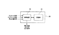
図2は、本例に係るエレベーター1の制御部20の構成を示すブロック図である。
図2に示すように、制御部20は、内部に演算装置19と記憶部21とを備えている。
演算装置19は、論理演算を行うマイクロコンピュータで構成されており、停止位置信号、FLSセット信号、FLSリセット信号を受け取る。演算装置19は、その演算によって乗りかご12の状況を検出し、電力供給オン・オフ信号を送出してモータ105を駆動する電源への電力の供給を制御し、昇降路11内の乗りかご12の昇降移動を制御する。また、記憶部21は不揮発性メモリで構成されており、制御部20に入力されたFLSセット信号を一時的に保存する。
FIG. 2 is a block diagram illustrating a configuration of the
As shown in FIG. 2, the
The
図3は、乗りかご12に搭載される位置検出センサ80の平面視図と斜視図である。図3Aは乗りかご12に搭載される位置検出センサ80の平面視図であり、図3Bは位置検出センサ80の斜視図である。
FIG. 3 is a plan view and a perspective view of the
図3Aに示すように、位置検出センサ80は、以下に詳述する被検出体81〜83を検出するため、3つのセンサユニット80A〜80Cを並列に配置した構成である。ここでは、発光部801と受光部802を備えた光電センサを用いた例を示し、乗りかご12下に、1軸の光電センサを3つ並列に配置している。図中の80a〜80cは、各光電センサの光ビームを示す。また、センサユニット80A〜80Cは、図3Bに示すように同一の凹形状を有するユニットであり、側面を合致させた状態で一列に配置されている。
As shown in FIG. 3A, the
図4は、乗り場敷居部101,102に配置される被検出体81〜83を示す斜視図である。
図4Aは、中間階のエレベーター乗場50の乗場敷居102に取り付けられる停止階検出用の被検出体81の斜視図であり、図4Bは、最下階のエレベーター乗場51の乗場敷居101に取り付けられる停止階検出用の被検出体82の斜視図であり、図4Cは、被検出体82の下方に取り付けられるファイナルリミットスイッチ用の被検出体83の斜視図である。
FIG. 4 is a perspective view showing the detected
FIG. 4A is a perspective view of a
図4Aに示すように、被検出体81は、被検出体81を乗場敷居102に装着するための平板状の取付部81dと、所定の間隔を隔てて取付部81dに取り付けられた2枚の遮蔽板81a、81cとを備えている。遮蔽板81a、81cは、それぞれ位置検出センサ80のセンサユニット80A、80Cに対応するものである。遮蔽板81aによってセンサユニット80Aの発光部801から受光部802への光ビームを遮断し、遮蔽板81cによってセンサユニット80Cの発光部801から受光部802への光ビームを遮断する。
As shown in FIG. 4A, the detected
図4Bに示すように、第2の被検出体である被検出体82は、被検出体82を乗場敷居101に装着するための平板状の取付部82dと、所定の間隔を隔てて取付部82dに取り付けられた2枚の遮蔽板82b、82cとを備えている。遮蔽板82b、81cは、それぞれ位置検出センサ80のセンサユニット80B、80Cに対応するものである。遮蔽板82bによってセンサユニット80Bの発光部801から受光部802への光ビームを遮断し、遮蔽板82cによってセンサユニット80Cの発光部801から受光部802への光ビームを遮断する。
As shown in FIG. 4B, the
図4Cに示すように、第1の被検出体である被検出体83は、被検出体83を昇降路11内に装着するための平板状の取付部83dと、所定の間隔を隔てて取付部83dに取り付けられた3枚の遮蔽板83a、83b、83cとを備えている。遮蔽板83a、83b、83cは、それぞれ位置検出センサ80のセンサユニット80A、80B、80Cに対応するものである。遮蔽板83aによってセンサユニット80Aの発光部801から受光部802への光ビームを遮断し、遮蔽板83bによってセンサユニット80Bの発光部801から受光部802への光ビームを遮断し、遮蔽板83cによってセンサユニット80Cの発光部801から受光部802への光ビームを遮断する。
As shown in FIG. 4C, the
上述した被検出体81の遮蔽板81a、81c及び被検出体82の遮蔽板82b、82cの上下方向の長さは、各エレベーター乗場50,51の停止位置に対応した停止ゾーンの長さに一致するように形成されている。ファイナルリミットスイッチ用の被検出体83の遮蔽板83a、83b、83cの上下方向の長さは、ファイナルリミットスイッチ60をオン状態にするFLSセットゾーンの長さに一致するように形成されている。
The vertical lengths of the
本例によれば、過下降によって昇降路11を下降してきた乗りかご12の位置検出センサ80が、ファイナルリミットスイッチ60をオンするFLSセットゾーンに入ったことを検出できればよいので、ファイナルリミットスイッチ用の被検出体83の遮蔽板83a、83b、83cの上下方向の長さは、最下階のエレベーター乗場51から緩衝器104までの距離に合致させる必要はない。従って、被検出体83を長くする必要がないため、遮蔽板83a、83b、83cが傾く可能性が少なくなり、ファイナルリミットスイッチ60の精度を向上させることができる。
According to this example, it is only necessary to detect that the
また、本例の被検出体81〜83は、センサユニット80の発光部801から受光部802への光ビームを遮断できるプラスチック等の材質で構成されているが、被検出体81〜83を同一の材料で構成することにより製造コストを抑えることができる。
Further, the detected
図5は、本例による位置検出センサ80と被検出体81〜83との検知パターンを示す図である。すなわち、図5は位置検出センサ80の検知の組合せパターンを例示する図であり、中間階の停止ゾーンを識別するパターンと、最下階の停止ゾーンを識別するパターンと、ファイナルリミットスイッチをオン状態にするFLSセットゾーンを識別するパターンを示したものである。
FIG. 5 is a diagram showing detection patterns of the
図表の縦軸は、位置検出センサ80が被検出体を検出する場所を示し、横軸は位置検出センサ80のセンサユニット80A〜80Cの検知結果を示す。POS1はセンサユニット80Aの検知結果、POS2はセンサユニット80Bの検知結果、POS3はセンサユニット80Cの検知結果を示す。また、図表中の0は各センサユニットが被検出体の遮蔽板を検知していない状態を示し、1は各センサユニットが被検出体の遮蔽板を検知している状態を示す。
The vertical axis of the chart indicates the location where the
乗りかご12が中間階のエレベーター乗場50の停止ゾーンにいるとき、位置検出センサ80のセンサユニット80Aと80Cは、中間階のエレベーター乗場50の乗場敷居102に取り付けられた被検出体81の遮蔽板81aと81cによって遮光されるため、図5の上段に示すように、位置検出センサ80の検知パターンは「1,0,1」となる。
When the
乗りかご12が最下階のエレベーター乗場51の停止ゾーンにいるとき、位置検出センサ80のセンサユニット80Bと80Cは、最下階のエレベーター乗場51の乗場敷居101に取り付けられた被検出体82の遮蔽板81bと81cによって遮光されるため、図5の中段に示すように、位置検出センサ80の検知パターンは「0,1,1」となる。
When the
乗りかご12がファイナルリミットスイッチ60をオンするFLSセットゾーンにいるとき、位置検出センサ80のセンサユニット80A〜80Cは、昇降路11内部に取り付けられた被検出体83の遮蔽板83a〜83cによって遮光されるため、図5の下段に示すように、位置検出センサ80の検知パターンは「1,1,1」となる。
When the
位置検出センサ80が検知パターン「1,0,1」を検知したときは、位置検出センサ80は、中間階の停止位置信号を制御部20へ送出する。制御部20は、中間階の停止位置信号を受け取ることにより、乗りかご12が中間階のエレベーター乗場50の停止ゾーンにいることを認識し、乗りかご12を中間階のエレベーター乗場50に停止させるとともに、乗りかご側扉110及び中間階の乗場側扉109を開閉させる。
When the
位置検出センサ80が検知パターン「0,1,1」を検知したときは、位置検出センサ80は、最下階の停止位置信号を制御部20へ送出する。制御部20は、最下階の停止位置信号を受け取ることにより、乗りかご12が最下階のエレベーター乗場51の停止ゾーンにいることを認識し、乗りかご12を最下階のエレベーター乗場51に停止させるとともに、乗りかご側扉110及び最下階の乗場側扉109を開閉させる。
When the
位置検出センサ80が検知パターン「1,1,1」を検知したときは、位置検出センサ80は、FLSセット信号を制御部20へ送出する。制御部20は、FLSセット信号を受け取ることにより、乗りかご12が最下階のエレベーター乗場51の停止ゾーンよりも下方にいることを認識し、何らかの理由で過下降が発生したことを認識する。FLSセット信号を受け取った制御部20は、電力供給オフ信号を出力し、モータ105への電力の供給を遮断して、乗りかご12を緊急停止させる。なお、過下降が生じたことの識別には、検知パターン「0,1,1」から、検知パターン「1,1,1」に遷移したことを識別条件に加えてもよい。
When the
また、本例の被検出体82は、乗りかご12が最下階のエレベーター乗場51の停止ゾーンに存在していることを識別させる機能に加えて、ファイナルリミットスイッチ60をリセットするための識別機能を兼ねている。
Further, the detected
すなわち、復旧作業により過下降の原因が解消された場合には、ファイナルリミットスイッチ60をオンの状態からオフの状態に戻す必要が生じる。また、過下降の原因が解消された場合には、過下降により下降していた昇降路11内の乗りかご12を上昇させて、エレベーター1を通常運転の状態に戻す必要も生じる。
That is, when the cause of the excessive descent is eliminated by the recovery work, it is necessary to return the final limit switch 60 from the on state to the off state. In addition, when the cause of the excessive lowering is eliminated, it is necessary to raise the
過下降の原因が解消されたエレベーター1を通常運転の状態に戻す作業を行う際に、過下降状態の位置にあった乗りかご12を上昇させるが、本例では、その際に、被検出体82の遮蔽板82bによってセンサユニット80Bの発光部801から受光部802への光ビームを遮断し、遮蔽板82cによってセンサユニット80Cの発光部801から受光部802への光ビームを遮断する。その結果、位置検出センサ80が、図5の中段に示す検知パターン「0,1,1」を検知する。
When performing the operation of returning the
位置検出センサ80が検知パターン「0,1,1」を検知したときは、位置検出センサ80は、FLSリセット信号を制御部20へ送出する。制御部20は、FLSリセット信号を受け取ることにより、過下降の原因が解消したことを認識する。FLSリセット信号を受け取った制御部20は、電力供給オン信号を出力し、モータ105への電力の供給を再開して、ファイナルリミットスイッチ60をオフの状態にする。なお、過下降の原因が解消してファイナルリミットスイッチ60をオフ状態にすることの識別には、検知パターン「1,1,1」から、検知パターン「0,1,1」に遷移したことを識別条件に加えてもよい。
When the
このように、本例では、第2の被検出体である被検出体82は、乗りかご12が最下階のエレベーター乗場51の停止ゾーンに存在していることを識別する機能に加えて、ファイナルリミットスイッチ60をリセットする機能を有しているので、ファイナルリミットスイッチ60をリセットするために特別な部材を設ける必要がなくなる。さらには、FLSセット信号が送出され続けるいわゆるオン故障が発生した場合であっても、ファイナルリミットスイッチ60をリセットする際に別の信号であるFLSリセット信号を用いているので、ファイナルリミットスイッチ60がリセットされた際に、オン故障が発生していることを認識することができる。
Thus, in this example, in addition to the function of identifying that the detected
次に、ファイナルリミットスイッチ60の動作を含めた本発明のエレベーター1の動作について、フローチャートを用いて説明する。
図6は、本例にかかるエレベーター1の動作フローチャートである。
Next, operation | movement of the
FIG. 6 is an operation flowchart of the
図6に示すように、エレベーター1に何らかの異常が発生した場合に(ステップS1)、乗りかご12の位置検出センサ80のセンサユニット80A〜80Cが、ファイナルリミットスイッチ用の被検出体83の遮蔽板83a〜83cによって遮光されるか否かの検出が行われる。エレベーター1に発生した異常が過下降であって、センサユニット80A〜80Cが、ファイナルリミットスイッチ用の被検出体83の遮蔽板83a〜83cによって遮光された場合(検知パターンが図5に示す「1,1,1」となった場合)には、位置検出センサ80は、制御部20にFLSセット信号を送出する(ステップS2のYES)。一方、エレベーター1に発生した異常が過下降以外のものである場合には、ファイナルリミットスイッチ用の被検出体83の遮蔽板83a〜83cによって、位置検出センサ80のセンサユニット80A〜80Cが遮光されるか否かの検知を継続する(ステップS2のNO)。
As shown in FIG. 6, when any abnormality occurs in the elevator 1 (step S <b> 1), the
ステップS2において、位置検出センサ80から送出されたFLSセット信号を受け取った制御部20は、電力供給オフ信号を電源へ送出し、モータ105への電力の供給を遮断して、乗りかご12を緊急停止させる。同時に、制御部20は、受け取ったFLSセット信号を記憶部21に記憶させて、電源への電力供給を遮断する状態を維持する(ステップS3)。これにより、自動運転によってファイナルリミットスイッチ60がリセットされてしまうことを禁止する。
In step S2, the
次に、電源への電力供給が遮断された状態(ファイナルリミットスイッチ60をオンした状態)で、過下降が発生した原因を取り除くための復旧作業が行われる(ステップS4)。 Next, in a state where the power supply to the power source is interrupted (a state where the final limit switch 60 is turned on), a recovery operation is performed to remove the cause of the excessive lowering (step S4).
次に、位置検出センサ80が、最下階検知用の被検出体82の遮蔽板82b、82cによって遮蔽されるか否かの検出が行われる(ステップS6)。
被検出体82の遮蔽板82b、82cによって、位置検出センサ80のセンサユニット80B、80Cが遮光された場合(検知パターンが図5に示す「0,1,1」となった場合)には、位置検出センサ80は、復旧作業が終了したものとして、制御部20にFLSリセット信号を送出する(ステップS5のYES)。一方、位置検出センサ80のセンサユニット80B、80Cが遮光されない場合(検知パターンが図5に示す「0,1,1」とならない場合)には、引き続き、最下階検知用の被検出体82の遮蔽板82b、82cによって、位置検出センサ80のセンサユニット80B、80Cが遮蔽されるか否かの検出が行われる(ステップS5のNO)。
Next, it is detected whether or not the
When the
ステップS5において、位置検出センサ80から送出されたFLSリセット信号を受け取った制御部20は、電力供給オン信号を電源へ送出して、モータ105を駆動状態とし、エレベーター1を通常運転の状態へ復帰させる(ステップS6)。
In step S5, the
なお、本例では、FLSセット信号により電力供給オフ信号を送出されて電源への電力の供給が遮断された後、FLSリセット信号により電力供給オン信号が送出されてファイナルリミットスイッチ60がリセットされるまでの間は、制御部20の記憶部21に保存されたFLSセット信号によって、電源への電力供給を遮断する状態が維持される。
In this example, after the power supply off signal is sent by the FLS set signal and the power supply to the power supply is cut off, the power supply on signal is sent by the FLS reset signal and the final limit switch 60 is reset. Until that time, the state where the power supply to the power source is cut off is maintained by the FLS set signal stored in the
なお、本発明は上述しかつ図面に示した実施の形態に限定されるものではなく、特許請求の範囲に記載した発明の要旨に逸脱しない範囲内で種々の変形実施が可能である。例えば、本例では、ファイナルリミットスイッチ60の構成として、位置検出センサの発光部と受光部との間を遮蔽する遮蔽板を有する被検知体を用いているが、位置検出センサから出射されるビームを反射する反射板を備えた被検知体を用いてもよい。 The present invention is not limited to the embodiments described above and shown in the drawings, and various modifications can be made without departing from the spirit of the invention described in the claims. For example, in this example, as the configuration of the final limit switch 60, a detection object having a shielding plate that shields between the light emitting unit and the light receiving unit of the position detection sensor is used, but the beam emitted from the position detection sensor It is also possible to use a detection object provided with a reflector that reflects the light.
1・・・エレベーター、10・・・巻上機、11・・・昇降路、12・・・乗りかご、13・・・ロープ、14・・・釣合錘、16・・・機械室、20・・・制御部、21・・・記憶部、50,51・・・エレベーター乗場、60・・・ファイナルリミットスイッチ、80・・・位置検出センサ、81,82、83・・・被検知体、101、102・・・乗場敷居、103・・・ピット、104・・・緩衝器、105・・・モータ、109・・・乗場側扉、110・・・乗りかご側扉
DESCRIPTION OF
Claims (4)
前記乗りかごを制御する制御部と、
前記乗りかごに取り付けられた、昇降路内の乗りかごの位置を検出するための位置検出センサと、
前記位置検出センサによって検知される前記昇降路内に設けられた第1の被検出体と、
前記昇降路内において前記第1の被検出体よりも高い位置に設けられた、前記位置検出センサによって検知される第2の被検出体と、
最下階における前記乗りかごの行き過ぎを検知して、前記乗りかごを停止させるファイナルリミットスイッチと、を備え、
前記乗りかごが昇降路内を下降する際に、前記位置検出センサが前記第1の被検出体を検知した場合には、前記ファイナルリミットスイッチをオン状態にする信号を出力して、前記乗りかごの駆動部への電力の供給を遮断し、その後、前記乗りかごが昇降路内を上昇する際に、前記位置検出センサが前記第2の被検出体を検知した場合には、前記ファイナルリミットスイッチをオフ状態にする信号を出力する
エレベーター。 A car that goes up and down the hoistway,
A control unit for controlling the car;
A position detection sensor attached to the car for detecting the position of the car in the hoistway;
A first object to be detected provided in the hoistway detected by the position detection sensor;
A second object to be detected by the position detection sensor provided at a position higher than the first object to be detected in the hoistway;
A final limit switch for detecting the overtravel of the car on the lowest floor and stopping the car,
When the position detection sensor detects the first object to be detected when the car descends in the hoistway, it outputs a signal for turning on the final limit switch, and the car When the position detection sensor detects the second object to be detected when the car is raised in the hoistway after the power supply to the driving unit is cut off, the final limit switch Elevator that outputs a signal to turn off.
請求項1に記載のエレベーター。 The elevator according to claim 1, wherein the control unit includes a storage unit that stores a signal for turning on the final limit switch.
前記乗りかごが昇降路内を下降する際に、前記位置検出センサが前記第2の被検出体を検知した場合に、前記乗りかごに設けられているドアの開閉を行う
請求項1に記載のエレベーター。 The controller is
The door provided in the said car is opened and closed when the said position detection sensor detects a said 2nd to-be-detected object, when the said car descends the inside of a hoistway. Elevator.
請求項1〜3のいずれか一項に記載のエレベーター。
The elevator according to any one of claims 1 to 3, wherein the first object to be detected and the second object to be detected are flat members and are made of the same material.
Priority Applications (2)
| Application Number | Priority Date | Filing Date | Title |
|---|---|---|---|
| JP2016063897A JP2017178483A (en) | 2016-03-28 | 2016-03-28 | Elevator |
| CN201611020191.3A CN107235395B (en) | 2016-03-28 | 2016-11-18 | elevator |
Applications Claiming Priority (1)
| Application Number | Priority Date | Filing Date | Title |
|---|---|---|---|
| JP2016063897A JP2017178483A (en) | 2016-03-28 | 2016-03-28 | Elevator |
Publications (1)
| Publication Number | Publication Date |
|---|---|
| JP2017178483A true JP2017178483A (en) | 2017-10-05 |
Family
ID=59982927
Family Applications (1)
| Application Number | Title | Priority Date | Filing Date |
|---|---|---|---|
| JP2016063897A Pending JP2017178483A (en) | 2016-03-28 | 2016-03-28 | Elevator |
Country Status (2)
| Country | Link |
|---|---|
| JP (1) | JP2017178483A (en) |
| CN (1) | CN107235395B (en) |
Families Citing this family (2)
| Publication number | Priority date | Publication date | Assignee | Title |
|---|---|---|---|---|
| CN109648906B (en) * | 2019-02-01 | 2024-06-21 | 宁波长荣酿造设备有限公司 | Squeezer and electric protection device |
| CN112551300B (en) * | 2020-12-08 | 2022-12-20 | 上海三菱电梯有限公司 | Elevator safety protection system |
Citations (4)
| Publication number | Priority date | Publication date | Assignee | Title |
|---|---|---|---|---|
| JPH0687574A (en) * | 1992-09-10 | 1994-03-29 | Hitachi Ltd | End floor safety device for elevator |
| JP2012224422A (en) * | 2011-04-18 | 2012-11-15 | Hitachi Ltd | Elevator position detecting device and method |
| JP2012254866A (en) * | 2011-06-09 | 2012-12-27 | Mitsubishi Electric Corp | Terminal switch device of elevator |
| JP2015016982A (en) * | 2013-07-12 | 2015-01-29 | 三菱電機株式会社 | Elevator end point switch device |
Family Cites Families (6)
| Publication number | Priority date | Publication date | Assignee | Title |
|---|---|---|---|---|
| JPH0811671B2 (en) * | 1990-11-20 | 1996-02-07 | フジテック株式会社 | Elevator safety equipment |
| JP2007112561A (en) * | 2005-10-19 | 2007-05-10 | Mitsubishi Electric Corp | Elevator control device |
| JP2007217136A (en) * | 2006-02-17 | 2007-08-30 | Toshiba Elevator Co Ltd | Elevator controller |
| JP5814734B2 (en) * | 2011-10-11 | 2015-11-17 | 三菱電機ビルテクノサービス株式会社 | Gap size inspection device for elevator landing device and clearance size inspection method for elevator landing device |
| CN202744128U (en) * | 2012-07-23 | 2013-02-20 | 杭州西奥电梯有限公司 | Protection device for high-speed elevator end station |
| JP2014040320A (en) * | 2012-08-24 | 2014-03-06 | Hitachi Ltd | Safety device of elevator and operation method using the same |
-
2016
- 2016-03-28 JP JP2016063897A patent/JP2017178483A/en active Pending
- 2016-11-18 CN CN201611020191.3A patent/CN107235395B/en not_active Expired - Fee Related
Patent Citations (4)
| Publication number | Priority date | Publication date | Assignee | Title |
|---|---|---|---|---|
| JPH0687574A (en) * | 1992-09-10 | 1994-03-29 | Hitachi Ltd | End floor safety device for elevator |
| JP2012224422A (en) * | 2011-04-18 | 2012-11-15 | Hitachi Ltd | Elevator position detecting device and method |
| JP2012254866A (en) * | 2011-06-09 | 2012-12-27 | Mitsubishi Electric Corp | Terminal switch device of elevator |
| JP2015016982A (en) * | 2013-07-12 | 2015-01-29 | 三菱電機株式会社 | Elevator end point switch device |
Also Published As
| Publication number | Publication date |
|---|---|
| CN107235395A (en) | 2017-10-10 |
| CN107235395B (en) | 2019-03-19 |
Similar Documents
| Publication | Publication Date | Title |
|---|---|---|
| JP5442679B2 (en) | Elevator control device | |
| JP5516729B2 (en) | Elevator system | |
| JP5321731B2 (en) | Elevator with safe position sensor | |
| JP2011102163A (en) | Elevator system and control method for the same | |
| CN102556791B (en) | Position detection apparatus for elevator car | |
| JP5741746B2 (en) | Elevator system | |
| JPWO2011148411A1 (en) | Electronic safety elevator | |
| JP5354575B2 (en) | Elevator and elevator control method | |
| JP2012066881A (en) | Safety elevator | |
| JP2011063354A (en) | Elevator system | |
| US20190210832A1 (en) | Elevator system and method of positioning an elevator car with high accuracy | |
| CN108529368B (en) | Elevator maintenance support system | |
| JP5985686B1 (en) | elevator | |
| JP5944950B2 (en) | Elevator equipment | |
| JP2017178483A (en) | Elevator | |
| JP2012171758A (en) | Elevator system | |
| JP5449127B2 (en) | elevator | |
| JPWO2008056398A1 (en) | Elevator equipment | |
| CN107555288A (en) | Limit switch system | |
| WO2007066375A1 (en) | Door safety device for elevator | |
| JP2010168185A (en) | Elevator device | |
| JP2012017154A (en) | Elevator landing apparatus | |
| JP2012162342A (en) | Elevator safety apparatus, elevator, and method for controlling the elevator | |
| JP6654163B2 (en) | Elevator | |
| JP6289291B2 (en) | Elevator apparatus and elevator stop position determination method |
Legal Events
| Date | Code | Title | Description |
|---|---|---|---|
| A621 | Written request for application examination |
Free format text: JAPANESE INTERMEDIATE CODE: A621 Effective date: 20180125 |
|
| A131 | Notification of reasons for refusal |
Free format text: JAPANESE INTERMEDIATE CODE: A131 Effective date: 20181120 |
|
| A02 | Decision of refusal |
Free format text: JAPANESE INTERMEDIATE CODE: A02 Effective date: 20190521 |