JP2017178607A - Passenger conveyor - Google Patents
Passenger conveyor Download PDFInfo
- Publication number
- JP2017178607A JP2017178607A JP2016071926A JP2016071926A JP2017178607A JP 2017178607 A JP2017178607 A JP 2017178607A JP 2016071926 A JP2016071926 A JP 2016071926A JP 2016071926 A JP2016071926 A JP 2016071926A JP 2017178607 A JP2017178607 A JP 2017178607A
- Authority
- JP
- Japan
- Prior art keywords
- side plate
- body frame
- exterior side
- main body
- passenger conveyor
- Prior art date
- Legal status (The legal status is an assumption and is not a legal conclusion. Google has not performed a legal analysis and makes no representation as to the accuracy of the status listed.)
- Granted
Links
Images


Landscapes
- Escalators And Moving Walkways (AREA)
Abstract
Description
本発明は、乗客コンベアに関し、例えば、エスカレータに適用して好適なものである。 The present invention relates to a passenger conveyor, and is suitable for application to an escalator, for example.
エスカレータに代表される乗客コンベアは、建築構造物である上階床と下階床とを上下に跨ぐように設置されており、上階床と下階床とを上下に跨ぐ断面凹字状の本体フレーム内において無端状に連結された複数の踏段が上階及び下階間を斜め上方又は斜め下方に循環移動する構成となっている。また無端状に連結された複数の踏段の進行方向に沿って左右両側には一対の欄干が立設され、これら欄干の上側にそれぞれ踏段と同期して走行する手摺りが配設されている。 Passenger conveyors typified by escalators are installed so as to straddle the upper and lower floors, which are building structures, and have a concave cross section that straddles the upper and lower floors. A plurality of steps connected endlessly in the main body frame is configured to circulate and move diagonally upward or diagonally downward between the upper floor and the lower floor. A pair of balustrades are erected on the left and right sides along the traveling direction of a plurality of steps connected endlessly, and handrails that run in synchronization with the steps are arranged above the balustrades.
このような乗客コンベアを上階床と下階床とで支持する支持機構部は、乗客コンベアの本体フレームの両終端に備えられた支持アングルを建築構造物に形成したアングル受台によって支持する構造となっている。よって、乗客コンベア自身の重量と乗客や荷物等の積載加重はこの支持機構部によって支えられる。また、近年、少なくとも一方の支持機構部に摺動構造を設け、地震などで大きな層間変位が発生して本体フレームと建築構造物の上階床又は下階床との長手方向の間隔が過大になったり、逆に過小になったりした場合、本体フレームの長手方向の移動に追従可能とした耐震構造の乗客コンベアが採用されている。 The support mechanism for supporting the passenger conveyor between the upper floor and the lower floor is a structure in which support angles provided at both ends of the main body frame of the passenger conveyor are supported by angle pedestals formed in the building structure. It has become. Therefore, the weight of the passenger conveyor itself and the loading weight of passengers, luggage, etc. are supported by this support mechanism. In recent years, at least one support mechanism is provided with a sliding structure, and a large interlayer displacement occurs due to an earthquake or the like, resulting in an excessive longitudinal distance between the main body frame and the upper or lower floor of the building structure. If it becomes too small or conversely too small, a passenger conveyor having an earthquake-resistant structure that can follow the movement of the main body frame in the longitudinal direction is adopted.
そして本体フレームの両側部には、その側部を覆う外装側板が取り付けられていると共に、本体フレームの両終端に位置する外装側板は、その端部が建築構造物の上階床及び下階床に当接するようにして設けられている(特許文献1)。 And the exterior side plate which covers the side part is attached to the both sides of the body frame, and the end part of the exterior side plate located at both ends of the body frame is the upper floor and the lower floor of the building structure. (Patent Document 1).
ところで、上述した耐震構造を有する乗客コンベアでは、地震の影響等で建築構造物の上階床と下階床との間で層間変位が発生した場合、本体フレームの長手方向の移動に欄干や踏段や外装底板等の構成物品は追従可能としてあるものの、本体フレームに取り付けられる外装側板は、その下部が下階床に固定されているために水平方向の変位に対応することができず、本体フレームに追従できないために、建築構造物の上階床と下階床との間で大きな力を受け、破損して落下するおそれがあった。 By the way, in the passenger conveyor having the earthquake-resistant structure described above, when an interlayer displacement occurs between the upper floor and the lower floor of the building structure due to the influence of the earthquake, the rail of the main body frame is moved in the longitudinal direction. However, the exterior side plate attached to the main body frame cannot support horizontal displacement because its lower part is fixed to the lower floor, but the main body frame Because it cannot follow, there is a risk of receiving a large force between the upper floor and the lower floor of the building structure, resulting in damage and falling.
本発明は以上の点を考慮してなされたもので、地震動等により外装板が破損することを防止し得る乗客コンベアを提案しようとするものである。 The present invention has been made in view of the above points, and an object of the present invention is to propose a passenger conveyor that can prevent the exterior plate from being damaged by earthquake motion or the like.
かかる課題を解決するため本発明においては、長手方向に移動可能に設置された本体フレーム内を、無端状に連結されたステップが循環移動する乗客コンベアにおいて、本体フレームが設置された床面に固定されることなく、本体フレームの側部を覆うように当該本体フレームの両側部にそれぞれ取り付けられた外装側板と、床面に固定され、外装側板の幅方向への外装側板の振れを抑制する振れ抑制ガード機構とを備えるようにした。 In order to solve such a problem, in the present invention, in a passenger conveyor in which steps connected in an endless manner are circulated and moved in a main body frame installed so as to be movable in the longitudinal direction, it is fixed to the floor surface on which the main body frame is installed. The outer side plate attached to both sides of the main body frame so as to cover the side portion of the main body frame, and the vibration that is fixed to the floor and suppresses the outer side plate from swinging in the width direction of the outer side plate. And a suppression guard mechanism.
本発明によれば、層間変位により外装側板が破損することを防止し得る乗客コンベアを実現できる。 ADVANTAGE OF THE INVENTION According to this invention, the passenger conveyor which can prevent that an exterior side board is damaged by interlayer displacement is realizable.
以下、図面について、本発明の一実施の形態を詳述する。 Hereinafter, an embodiment of the present invention will be described in detail with reference to the drawings.
なお、本明細書においては、「ステップ」の用語には、エスカレータの複数の踏段だけでなく、エスカレータを水平化したパレット式の動く歩道の複数の踏台やベルトコンベアのゴムベルト式の動く歩道の踏台も含まれるものとする。 In this specification, the term “step” includes not only a plurality of steps of an escalator, but also a plurality of steps of a pallet-type moving sidewalk that leveles the escalator and a rubber belt-type moving sidewalk of a belt conveyor. Is also included.
(1)実施の形態
(1−1)本実施の形態による乗客コンベアの構成
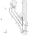
図1及び図4を参照して、本実施の形態の乗客コンベアの構成について説明する。本実施の形態の乗客コンベア1は、建築構造物である建屋上階床10と建屋下階床11とを上下に跨ぐように設置される耐震構造を有するエスカレータであり、建屋上階床10と建屋下階床11とを上下に跨ぐ断面凹字状の本体フレーム2内において無端状に連結されたステップ3が上階及び下階間を斜め上方又は斜め下方に循環移動する構成を有する。無端状に連結されたステップ3の両側にはそれぞれ欄干4が立設され、これら欄干4上にそれぞれステップ3と同期して走行する移動手摺り5が配設されている。
(1) Embodiment (1-1) Configuration of Passenger Conveyor According to this Embodiment A configuration of a passenger conveyor according to this embodiment will be described with reference to FIGS. 1 and 4. The passenger conveyor 1 according to the present embodiment is an escalator having an earthquake-resistant structure that is installed so as to straddle a building
本体フレーム2は、長手方向の一端側(下階側)が建屋下階床11に形成された窪み25内に嵌め込まれ、その先端部に固定された建屋下階床側支持アングル19aがかかる窪み25内に形成された建屋下階床側アングル受台19bに支持されると共に、長手方向の他端側(上階側)に固定された建屋上階床側支持アングル18aが建屋上階床10に形成された建屋上階床側アングル受台18bによって支持されるようにして設置されている。
The
この場合、建屋下階床側支持アングル19a及び建屋下階床側アングル受台19b間には所定幅の建屋下階床側隙間14が設けられると共に、建屋上階床側支持アングル18a及び建屋上階床側アングル受台18b間にも所定幅の建屋上階床側隙間13が設けられており、これにより地震などで層間変位が発生して本体フレーム2がその長手方向に移動した場合においても、かかる移動が僅かな場合には、本体フレーム2が建屋上階床10や建屋下階床11に衝突して本体フレーム2や建屋上階床10及び建屋下階床11が破損することを有効に防止し得るようになされている。
In this case, a building lower
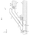
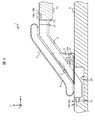
また建屋下階床側アングル受台19b及び建屋上階床側アングル受台18b間の間隔は、本体フレーム2に建屋下階床側支持アングル19aを加えた長さや本体フレーム2に建屋上階床側支持アングル18aを加えた長さよりも短く選定されており、これにより図2のように建屋下階床側支持アングル19aが建屋下階床側アングル受台19bの側面に当接するまで本体フレーム2が移動した場合や、図3のように建屋上階床側支持アングル18aが建屋上階床側アングル受台18bの側面に当接するまで本体フレーム2が移動した場合においても、建屋下階床側支持アングル19aが建屋下階床側アングル受台19bから外れたり、又は建屋上階床側支持アングル18aが建屋上階床側アングル受台18bから外れたりするのを防止し得るようになされている。
The space between the building lower floor angle receiving base 19b and the building upper
さらに乗客コンベア1には、本体フレーム2を支える中間支持体20が設けられている。中間支持体20には、層間変位が発生した場合に、長手方向に摺動するスライド部材21が設けられると共に、スライド部材21の上部に本体フレーム側支持体22が設けられ、スライド部材21の下部に建屋下階床側支持体23が設けられている。これにより本体フレーム2が長手方向に移動した場合も、スライド部材21によって支えられるため、建屋下階床11に乗客コンベア1が落下することを防止し得るようになされている。また本体フレーム側支持体22は本体フレーム2に固定され、建屋下階床側支持体23は建屋下階床11に固定されており、中間支持体20は本体フレーム2の長手方向の中間を支持する。なお、図1〜3では、スライド部材21は本体フレーム側支持体22に固定されているが、スライド部材21は建屋下階床側支持体23に固定されていてもよい。
Further, the passenger conveyor 1 is provided with an
またスライド部材21の長手方向の長さは、建屋下階床側隙間14や建屋上階床側隙間13よりも長く選定されており、これにより図2のように建屋下階床側支持アングル19aが建屋下階床側アングル受台19bの側面に当接するまで本体フレーム2が移動した場合や、図3のように建屋上階床側支持アングル18aが建屋上階床側アングル受台18bの側面に当接するまで本体フレーム2が移動した場合においても、スライド部材21が建屋下階床側支持体23から外れるのを防止し得るようになされている。
Further, the length in the longitudinal direction of the
一方、乗客コンベア1の両側部には、それぞれ本体フレーム2の側部を覆う外装側板6が取付けられている。外装側板6は、本体フレーム2の他端側(上階側)を覆う長手方向の他端側(上階側)の先端部が、建屋上階床側支持アングル18a及び建屋上階床10の建屋上階床側アングル受台18bの台部を側面側から覆うように、本体フレーム2よりも長く形成されている。
On the other hand,
そして外装側板6の他端側(上階側)の先端部は、外装側板6の他の部位とは切り離されて、これら先端部及び他の部位間に所定幅の外装側板隙間27が設けられている。これにより地震などにより本体フレーム2がその長手方向に移動した場合に、本体フレーム2と一体に移動する外装側板6の変位をかかる外装側板隙間27により吸収して、本体フレーム2の移動に伴う外装側板6の変形や破損を防止し得るようになされている。
And the front-end | tip part of the other end side (upper floor side) of the
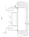
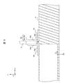
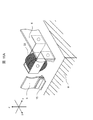
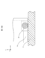
また本体フレーム2の一端側(下階側)を覆う外装側板6の長手方向の一端側(下階側)には、中間支持体20をも側面側から覆い隠す三角形状の三角形状カバー部6aが形成されている。そして外装側板6は、図5に示すように、かかる三角形状カバー部6aの下端面が建屋下階床11から僅かに浮き上がった状態で建屋下階床11と対向するように本体フレーム2に取り付けられており、これにより外装側板6の下端面及び建屋下階床11間には所定高さの抑制ガード隙間17が設けられている。これにより地震などで大きな層間変位が発生して本体フレーム2がその長手方向に移動した場合においても、外装側板6の三角形状カバー部6aが建屋下階床11から何らの抵抗を受けることなく本体フレーム2と一体に本体フレーム2の長手方向に自由に移動することができ、かくして本体フレーム2がその長手方向に移動することに起因する外装側板6の破損を防止し得るようになされている。
Further, on the one end side (lower floor side) in the longitudinal direction of the
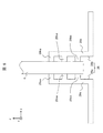
加えて、外装側板6の三角形状カバー部6aの下端側には、当該三角形状カバー部6aの下端部とほぼ同じ長さを有する振れ抑制ガード機構15が配設されている。振れ抑制ガード機構15は、外装側板6の三角形状カバー部6aの内側に配設された断面L字状の内側L字型ガード15aと、三角形状カバー部6aの外側に配設された断面L字状の外側L字ガード15bとから構成され、これら内側L字型ガード15a及び外側L字型ガード15bの垂直部16a及び16bにより外装側板6の三角形状カバー部6aの下端部を挟み込むように本体フレーム2の長手方向に沿って配置されている。また内側L字型ガード15a及び外側L字ガード15bの水平部16c及び16dは、それぞれボルト24等により建屋下階床11に固定されており、これにより外装側板6の三角形状カバー部6aの幅方向(本体フレーム2の長手方向と直交する方向であり、以下、これを本体フレーム2の幅方向と呼ぶ)の振れを抑制し得るようになされている。
In addition, on the lower end side of the
(1−2)本実施の形態の効果
以上の構成を有する本実施の形態の乗客コンベア1では、地震等により大きな層間変位が発生した場合に、本体フレーム2が建屋下階床側アングル受台19b及び建屋上階床側アングル受台18b間をその長手方向に移動する。この際、外装側板6は建屋下階床11に固定されていないため、本体フレーム2と一体に本体フレーム2の長手方向に移動することができる。従って、本乗客コンベア1によれば、地震等により層間変位が発生した場合においても外装側板6の破損を防ぐことができる。
(1-2) Effects of the present embodiment In the passenger conveyor 1 according to the present embodiment having the above-described configuration, when a large interlayer displacement occurs due to an earthquake or the like, the
また本乗客コンベア1では、外装側板6の三角形状カバー部6aの下端部を振れ抑制ガード機構15を構成する内側L字型ガード15a及び外側L字ガード15bにより挟み込むようにして保持しているため、外装側板6が本体フレーム6と一体に本体フレーム6の長手方向に移動することを邪魔することなく、当該外装側板6の本体フレーム2の幅方向の振れを抑止することができる。
Moreover, in this passenger conveyor 1, since the lower end part of the triangular-shaped
さらに本乗客コンベアでは、建屋下階床11と外装側板6との間に抑制ガード隙間17があっても、振れ抑制ガード15によって覆い隠すことができる。このことで、外観を損なうことなく、外装側板6の製作時や組立時の寸法公差を緩和することができ、乗客コンベア1の製作時間や組立時間の短縮及びコスト削減ができる。
Furthermore, in this passenger conveyor, even if there is a suppression guard gap 17 between the building
(2)他の実施の形態
なお上述の実施の形態においては、振れ抑制ガード機構15を構成する内側L字型ガード15a及び外側L字ガード15bの垂直部16a及び16bの外装側板6との接触面を平面とした場合について述べたが、本発明はこれに限らず、例えば図6に示すように、振れ抑制ガード機構28を構成する内側L字型ガード28a及び外側L字ガード28bの垂直部29a及び29bの外装側板6との接触面にこれら内側L字型ガード28a及び外側L字ガード28bの長手方向と平行に縦断面が四角形状の直線状の1又は複数の突部(以下、直線状の突部を突条と呼ぶ)29aa及び29baを設けるようにしてもよい。このようにすることによって外装側板6と内側L字型ガード28a及び外側L字ガード28bの垂直部29a及び29bとの接触面積を減らすことができるため、外装側板6が本体フレーム2と一体に本体フレーム2の長手方向に移動する際の外装側板6と内側L字型ガード28a及び外側L字ガード28bの垂直部29a及び29bとの間の摩擦を減らすことができ、これによりかかる移動時に外装側板6が内側L字型ガード28a及び外側L字ガード28bから受ける動摩擦力により変形や損傷等するのを防止することができる。
(2) Other Embodiments In the above-described embodiment, the
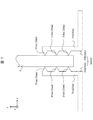
また図7及び図8に示すように、振れ抑制ガード機構30を構成する内側L字型ガード30a及び外側L字ガード30bの垂直部31a及び31bの外装側板6との接触面にこれら内側L字型ガード30a及び外側L字ガード30bの長手方向と平行に縦断面が三角形状の1又は複数の突条31aa及び31baを設けるようにしてもよい。このようにすることによって外装側板6と内側L字型ガード30a及び外側L字ガード30bの垂直部31a及び31bの外装側板6との接触面積を一層減らすことができるため、外装側板6が本体フレーム2と一体に本体フレーム2の長手方向に移動する際の外装側板6と内側L字型ガード30a及び外側L字ガード30bの垂直部31a及び31bとの間の摩擦を減らすことができ、これによりかかる移動時に外装側板6が内側L字型ガード30a及び外側L字ガード30bから受ける動摩擦力により変形や損傷等するのを防止することができる。なお突条31aa及び31baの縦断面形状は三角形状に限らず、要は、外装側板6と線接触可能な形状であれば、例えば半円形状等の種々の形状をとってもよい。
As shown in FIGS. 7 and 8, the inner L-shaped
さらに図7及び図9に示すように、内側L字型ガード32a及び外側L字ガード32bの垂直部33a及び33bの外装側板6との接触面に例えば錐形状の突起33aa及び33baを複数設けるようにしてもよい。このようにすることによって外装側板6と内側L字型ガード32a及び外側L字ガード32bの垂直部33a及び33bとの接触面積をより一層減らすことができるため、外装側板6が本体フレーム2と一体に本体フレーム2の長手方向に移動する際の外装側板6と内側L字型ガード32a及び外側L字ガード32bの垂直部33a及び33bとの間の摩擦を減らすことができ、これによりかかる移動時に外装側板6が内側L字型ガード32a及び外側L字ガード32bから受ける動摩擦力により変形や損傷等するのを防止することができる。なお突起33aa及び33baの形状は錐形状に限らず、要は、外装側板6と点接触可能な形状であれば例えば半球状等の種々の形状をとってもよい。
Further, as shown in FIGS. 7 and 9, a plurality of conical projections 33aa and 33ba, for example, are provided on the contact surfaces of the
さらに図6〜図9においては、内側L字型ガード28a、30a、32a及び外側L字ガード28b、30b、32bの垂直部29a、29b、31a、31b、33a、33bにこれら内側L字型ガード28a、30a、32a及び外側L字ガード28b、30b、32bの長手方向と平行に突部29aa、29ba、31aa、31ba、33aa、33baを設けるようにして振れ抑制ガード機構28、30、32と外装側板6との接触面積を減らす場合について述べたが、外装側板6に突部29aa、29ba、31aa、31ba、33aa、33baを設けることで接触面積を減らすようにしてもよい。
6-9, the inner L-shaped
また上述の実施の形態においては、建屋上階床側支持アングル18a及び建屋下階床側支持アングル19aのいずれもが建屋上階床側アングル受台18bや建屋下階床側アングル受台19bにボルト等で固定されていない場合について述べたが、本発明はこれに限らず、建屋上階床側支持アングル18a及び建屋下階床側支持アングル19aのいずれか一方が対応する建屋上階床側アングル受台18b又は建屋下階床側アングル受台19bに固定されていてもよい。
In the above-described embodiment, both of the building upper floor
さらに上述の実施の形態においては、振れ抑制ガード機構15を断面L字型の2つのガード(内側L字型ガード15a及び外側L字型ガード15b)から構成するようにした場合について述べたが、本発明はこれに限らず、これらガードのどちらか一方又は両方を断面三角形のガードにより構成するようにしてもよい。また、かかる2つのガードのうちのどちらか一方又は両方にリブがついていてもよい。
Furthermore, in the above-described embodiment, the case where the vibration
さらに上述の実施の形態においては、振れ抑制ガード機構15を構成する内側L字型ガード15a及び外側L字ガード15bの垂直部16a及び16bを同じ形の平面とした場合について述べたが、本発明はこれに限らず、一方が面接触となりもう一方が点接触となるように内側L字型ガード15a及び外側L字ガード15bを構成するようにしてもよい。
Further, in the above-described embodiment, the case where the
さらに上述の実施の形態においては、外装側板6を内側L字型ガード15a及び外側L字ガード15bにより挟み込むようにして保持する場合について述べたが、本発明はこれに限らず、内側L字型ガード15aと外装側板6との間及び/又は外側L字型ガード15bと外装側板6との間に隙間を設け、振れ抑制ガード機構15と外装側板6とを非接触とするようにしてもよい。
Furthermore, in the above-described embodiment, the case where the
さらに図1の外装側板6の三角形状カバー部6aの直角部B部に部材を追加することで、外装側板6と建屋下階床11との本体フレーム2の長手方向及び/又は本体フレーム2の幅方向に対する摩擦力を調整し、外装側板6を支え、隙間を埋めるようにしてもよい。
Further, by adding a member to the right-angled portion B of the
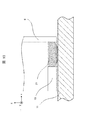
例えば、図10に示すように、本体フレーム2の幅方向に延伸し、底面が丸みを帯びており、本体フレーム2の長手方向及び幅方向に摺動可能な丸底部材21を、外装側板6の下部にボルト等で固定するようにしてもよい。
For example, as shown in FIG. 10, the
また図11A及び図11Bに示すように、1つ又は本体フレーム2の幅方向に連なる複数の、本体フレーム2の長手方向に転動可能なローラ部材22を外装側板6の下部にボルト等で固定するようにしてもよい。
Further, as shown in FIGS. 11A and 11B, one or a plurality of
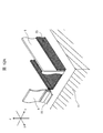
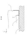
また図12A及び図12Bに示すように、本体フレーム2の幅方向に延伸するような巾木部材23を外装側板6の下部にボルト等で固定するようにしてもよい。このような構成でも、巾木部材23により外装側板6を支えるとともに、巾木部材23により摺動することが可能となる。また、図12Aに示すように、外装側板6の本体フレーム2の幅方向における意匠性の向上も図ることができる。
12A and 12B, a
さらに上述の実施の形態においては、乗客コンベア1がエスカレータである場合について述べたが、本発明はこれに限らず、この他、「動く歩道」等の乗客コンベアについても本発明を適用することができる。 Furthermore, in the above-mentioned embodiment, although the case where the passenger conveyor 1 was an escalator was described, this invention is not restricted to this, In addition, this invention is applicable also to passenger conveyors, such as a "moving sidewalk." it can.
1………乗客コンベア
2………本体フレーム
3………ステップ
4………欄干
5………移動手摺り
6………外装側板
10……建屋上階床
11……建屋下階床
13……建屋上階床側隙間
14……建屋下階床側隙間
15……振れ抑制ガード機構
15a…内側L字型ガード
15b…外側L字型ガード
17……抑制ガード隙間
18a…建屋上階床側支持アングル
18b…建屋上階床側アングル受台
19a…建屋下階床側支持アングル
19b…建屋下階床側アングル受台
20……中間支持体
21……丸底部材
22……ローラ部材
23……巾木部材
1 ………
Claims (9)
前記本体フレームが設置された床面に固定されることなく、前記本体フレームの側部を覆うように当該本体フレームの両側部にそれぞれ取り付けられた外装側板と、
前記床面に固定され、前記外装側板の幅方向への前記外装側板の振れを抑制する振れ抑制ガード機構と
を備えることを特徴とする乗客コンベア。 In the passenger conveyor in which the steps connected in an endless manner circulate in the main body frame installed so as to be movable in the longitudinal direction,
Without being fixed to the floor on which the main body frame is installed, exterior side plates attached to both side portions of the main body frame so as to cover the side portions of the main body frame,
A passenger conveyor, comprising: a vibration suppression guard mechanism which is fixed to the floor surface and suppresses the deflection of the exterior side plate in the width direction of the exterior side plate.
前記外装側板の内側に配設された内側ガードと、
前記外装側板の外側に配設された外側ガードと
を備え、
前記外装側板の一部又は全部の下端部を前記内側ガード及び前記外側ガードにより挟むようにして、前記外装側板の幅方向への前記外装側板の振れを抑制する
ことを特徴とする請求項1に記載の乗客コンベア。 The shake suppression guard mechanism is
An inner guard disposed inside the exterior side plate;
An outer guard disposed outside the exterior side plate,
2. The shake of the exterior side plate in the width direction of the exterior side plate is suppressed by sandwiching a part or all of the lower end portion of the exterior side plate between the inner guard and the outer guard. Passenger conveyor.
前記外装側板との接触面に1又は複数の突部を備える
ことを特徴とする請求項2に記載の乗客コンベア。 At least one of the inner guard and the outer guard is:
The passenger conveyor according to claim 2, further comprising one or a plurality of protrusions on a contact surface with the exterior side plate.
前記内側ガード及び前記外側ガードの長手方向と平行に直線状に形成された突条である
ことを特徴とする請求項3に記載の乗客コンベア。 The protrusion is
The passenger conveyor according to claim 3, wherein the passenger conveyor is a ridge formed linearly in parallel with the longitudinal direction of the inner guard and the outer guard.
縦断面が三角形状に形成された
ことを特徴とする請求項4に記載の乗客コンベア。 The protrusion is
The passenger conveyor according to claim 4, wherein the longitudinal section is formed in a triangular shape.
複数の突起である
ことを特徴とする請求項3に記載の乗客コンベア。 The protrusion is
It is a some protrusion. The passenger conveyor of Claim 3 characterized by the above-mentioned.
ことを特徴とする請求項3に記載の乗客コンベア。 The passenger conveyor according to claim 3, wherein the exterior side plate includes a round bottom member extending in a width direction of the main body frame at a lower portion.
ことを特徴とする請求項3に記載の乗客コンベア。 4. The passenger conveyor according to claim 3, wherein the exterior side plate includes one or a plurality of roller members that roll in the longitudinal direction of the exterior side plate in the lower part, which are continuous in the width direction of the main body frame.
ことを特徴とする請求項3に記載の乗客コンベア。
4. The passenger conveyor according to claim 3, wherein the exterior side plate includes a baseboard member extending in a width direction of the main body frame at a lower portion.
Priority Applications (1)
| Application Number | Priority Date | Filing Date | Title |
|---|---|---|---|
| JP2016071926A JP6518208B2 (en) | 2016-03-31 | 2016-03-31 | Passenger conveyor |
Applications Claiming Priority (1)
| Application Number | Priority Date | Filing Date | Title |
|---|---|---|---|
| JP2016071926A JP6518208B2 (en) | 2016-03-31 | 2016-03-31 | Passenger conveyor |
Publications (2)
| Publication Number | Publication Date |
|---|---|
| JP2017178607A true JP2017178607A (en) | 2017-10-05 |
| JP6518208B2 JP6518208B2 (en) | 2019-05-22 |
Family
ID=60003560
Family Applications (1)
| Application Number | Title | Priority Date | Filing Date |
|---|---|---|---|
| JP2016071926A Active JP6518208B2 (en) | 2016-03-31 | 2016-03-31 | Passenger conveyor |
Country Status (1)
| Country | Link |
|---|---|
| JP (1) | JP6518208B2 (en) |
Citations (2)
| Publication number | Priority date | Publication date | Assignee | Title |
|---|---|---|---|---|
| JPH07228462A (en) * | 1994-02-14 | 1995-08-29 | Hitachi Building Syst Eng & Service Co Ltd | Exterior bottom plate mounting structure for passenger conveyors |
| JP2015157689A (en) * | 2014-02-25 | 2015-09-03 | 株式会社日立製作所 | Passenger conveyor device |
-
2016
- 2016-03-31 JP JP2016071926A patent/JP6518208B2/en active Active
Patent Citations (2)
| Publication number | Priority date | Publication date | Assignee | Title |
|---|---|---|---|---|
| JPH07228462A (en) * | 1994-02-14 | 1995-08-29 | Hitachi Building Syst Eng & Service Co Ltd | Exterior bottom plate mounting structure for passenger conveyors |
| JP2015157689A (en) * | 2014-02-25 | 2015-09-03 | 株式会社日立製作所 | Passenger conveyor device |
Also Published As
| Publication number | Publication date |
|---|---|
| JP6518208B2 (en) | 2019-05-22 |
Similar Documents
| Publication | Publication Date | Title |
|---|---|---|
| KR102263794B1 (en) | Support for supporting a person conveying device on a structure | |
| JP5449467B2 (en) | Passenger conveyor | |
| CN101209797B (en) | Entrance safety device for passenger conveyer | |
| TWI813814B (en) | Motion guide device | |
| JP5546285B2 (en) | Passenger parapet | |
| JP2017178607A (en) | Passenger conveyor | |
| JP6134670B2 (en) | Passenger conveyor equipment | |
| JP6494556B2 (en) | Passenger conveyor | |
| JP6166166B2 (en) | Passenger conveyor | |
| JP2013245084A (en) | Man conveyor | |
| JP7086037B2 (en) | Passenger conveyor | |
| JP2015160720A (en) | passenger conveyor | |
| JP2014073889A (en) | Footstep of escalator | |
| JP6353819B2 (en) | Passenger conveyor | |
| JP6557195B2 (en) | Passenger conveyor | |
| JP2014012563A (en) | Passenger conveyor | |
| JP5721594B2 (en) | Elevator doorway equipment | |
| JP6568031B2 (en) | Passenger conveyor | |
| JP2016155656A (en) | Passage prevention device for passenger conveyor | |
| JP5676707B1 (en) | Oil scattering suppression mechanism for passenger conveyors | |
| WO2020202534A1 (en) | Truss support device for passenger conveyor | |
| CN113165840B (en) | Guide rail connecting device of elevator | |
| JP4977091B2 (en) | Floor joint device | |
| JP6904372B2 (en) | Man Conveyor Structure, Man Conveyor and Man Conveyor Structure Manufacturing Method | |
| KR20050108737A (en) | Shock and noise absorbing device of passenger conveyor |
Legal Events
| Date | Code | Title | Description |
|---|---|---|---|
| A621 | Written request for application examination |
Free format text: JAPANESE INTERMEDIATE CODE: A621 Effective date: 20180207 |
|
| A977 | Report on retrieval |
Free format text: JAPANESE INTERMEDIATE CODE: A971007 Effective date: 20181220 |
|
| A131 | Notification of reasons for refusal |
Free format text: JAPANESE INTERMEDIATE CODE: A131 Effective date: 20190108 |
|
| A521 | Request for written amendment filed |
Free format text: JAPANESE INTERMEDIATE CODE: A523 Effective date: 20190305 |
|
| TRDD | Decision of grant or rejection written | ||
| A01 | Written decision to grant a patent or to grant a registration (utility model) |
Free format text: JAPANESE INTERMEDIATE CODE: A01 Effective date: 20190416 |
|
| A61 | First payment of annual fees (during grant procedure) |
Free format text: JAPANESE INTERMEDIATE CODE: A61 Effective date: 20190419 |
|
| R150 | Certificate of patent or registration of utility model |
Ref document number: 6518208 Country of ref document: JP Free format text: JAPANESE INTERMEDIATE CODE: R150 |