JP2017179934A - How to construct a suspended roof frame - Google Patents

How to construct a suspended roof frame Download PDF

Info

Publication number
JP2017179934A
JP2017179934A JP2016069847A JP2016069847A JP2017179934A JP 2017179934 A JP2017179934 A JP 2017179934A JP 2016069847 A JP2016069847 A JP 2016069847A JP 2016069847 A JP2016069847 A JP 2016069847A JP 2017179934 A JP2017179934 A JP 2017179934A
Authority
JP
Japan
Prior art keywords
outer peripheral
column
roof frame
truss beam
truss
Prior art date
Legal status (The legal status is an assumption and is not a legal conclusion. Google has not performed a legal analysis and makes no representation as to the accuracy of the status listed.)
Pending
Application number
JP2016069847A
Other languages
Japanese (ja)
Inventor
元貴 川口
Motoki Kawaguchi
元貴 川口
龍一 田中
Ryuichi Tanaka
龍一 田中
Current Assignee (The listed assignees may be inaccurate. Google has not performed a legal analysis and makes no representation or warranty as to the accuracy of the list.)
Taisei Corp
Original Assignee
Taisei Corp
Priority date (The priority date is an assumption and is not a legal conclusion. Google has not performed a legal analysis and makes no representation as to the accuracy of the date listed.)
Filing date
Publication date
Application filed by Taisei Corp filed Critical Taisei Corp
Priority to JP2016069847A priority Critical patent/JP2017179934A/en
Publication of JP2017179934A publication Critical patent/JP2017179934A/en
Pending legal-status Critical Current

Links

Images

Landscapes

  • Conveying And Assembling Of Building Elements In Situ (AREA)

Abstract

PROBLEM TO BE SOLVED: To provide a construction method of a suspension roof frame that enables a suspension roof frame to be assembled at high accuracy.SOLUTION: A suspension roof frame 1 includes a plurality of outer peripheral columns 20, an outer peripheral beam 33 connecting the outer peripheral columns 20 to each other, a truss beam 31 disposed in a square frame form when seen in a planar view, and a connection member 34 connecting the outer peripheral column 20 with the truss beam 31. A construction method of the suspension roof frame includes: steps S11 to S13 for erecting the outer peripheral column 20 and then connecting the outer peripheral column 20 with the outer peripheral beam 33 in the air; a step S21 for installing a truss beam receiving bent 42 and placing a truss beam connection part 314 that is a part of the truss beam 31 on the truss beam receiving bent 42; steps S22, S23 for spanning the connection member 34 between the outer peripheral column 20 and the truss beam connection part 314; and steps S31, S32 for assembling the truss beam 31 in the air.SELECTED DRAWING: Figure 12

Description

本発明は、建物の屋根の下に大空間を形成するための吊り屋根架構の構築方法に関する。   The present invention relates to a method for constructing a suspended roof frame for forming a large space under a roof of a building.

従来より、音楽ホールや室内競技場などは、種々の催しにも対応できるように、大空間屋根架構が要請されてきた。この屋根架構としては、柱間隔を長スパン化するために、トラス梁構造、アーチ構造、シェル構造、膜構造が開発されてきた。このうち、アーチ構造、シェル構造、膜構造は、施工手順が複雑であるうえに、工期が長期化する場合が多く、屋根架構として採用されることは少なかった。これに対して、トラス梁構造は、構造形式が明快で、施工が容易であることから、屋根架構として数多く採用されてきた(特許文献1、2参照)。   Conventionally, a large space roof frame has been required for music halls and indoor stadiums to accommodate various events. As this roof frame, a truss beam structure, an arch structure, a shell structure, and a membrane structure have been developed in order to increase the span between columns. Among them, the arch structure, the shell structure, and the membrane structure have complicated construction procedures and often require a long construction period, and are rarely used as a roof frame. On the other hand, the truss beam structure has been widely adopted as a roof frame because of its clear structural form and easy construction (see Patent Documents 1 and 2).

例えば、特許文献1には、鉄骨トラス梁からなるドーム状構造物が開示されている。このドーム状構造物では、アーチ状をなす複数のトラス梁が略平行に配置されるとともに、これらトラス梁と交差するように、複数のトラス梁が略平行に配置され、ドーム状の屋根架構が形成されている。
また、特許文献2には、トラス張弦梁で構成した屋根架構が開示されている。トラス張弦梁は、並列配置された2本の上弦材と、これら上弦材に沿って配置された1本の下弦材と、上弦材と下弦材を連結する複数本の斜め材とで構成されている。
For example, Patent Document 1 discloses a dome-like structure made of steel truss beams. In this dome-shaped structure, a plurality of truss beams forming an arch shape are arranged substantially in parallel, and a plurality of truss beams are arranged substantially in parallel so as to intersect the truss beams, so that a dome-shaped roof frame is formed. Is formed.
Further, Patent Document 2 discloses a roof frame composed of trussed string beams. The truss string beam is composed of two upper chord members arranged in parallel, one lower chord member arranged along these upper chord members, and a plurality of oblique members connecting the upper chord material and the lower chord material. .

しかしながら、大規模な屋根架構をトラス梁のみで構成するには、屋根面を覆うために、長スパンでかつ梁せい(梁の高さ)が大きいトラス梁が必要であった。そこで、梁せいを低く抑えようとすると、交差するように架設したトラス梁で屋根面を支持するか、または、隣接するトラス梁同士の間隔を狭める必要があった。
また、トラス梁は多数の部材で構成されるため、特許文献1、2のようなトラス梁を多数配置すると、部材同士の接合箇所が多くなって工期が長期化する傾向があった。
また、屋根架構をトラス梁のみで構築すると、屋根面を支えるトラス梁の両端付近の柱や壁の近傍では、室内空間の天井高さが低くなり、使い勝手が低下する、という問題があった。
また、トラス梁は多数の斜め材で構成されるため、特許文献1、2のように多数のトラス梁を用いた屋根架構では、斜め材同士の接合箇所が多くなり、施工精度の確保が困難となる、という問題があった。
However, in order to construct a large-scale roof frame only with truss beams, a truss beam having a long span and a large beam length (the height of the beam) is necessary to cover the roof surface. Therefore, in order to keep the beams low, it was necessary to support the roof surface with truss beams installed so as to cross each other, or to narrow the interval between adjacent truss beams.
Further, since the truss beams are composed of a large number of members, when a large number of truss beams as in Patent Documents 1 and 2 are arranged, there is a tendency that the number of joints between the members increases and the construction period becomes longer.
In addition, when the roof frame is constructed with only the truss beams, there is a problem that the ceiling height of the indoor space is lowered near the columns and walls near both ends of the truss beams that support the roof surface, and the usability is lowered.
In addition, since the truss beams are composed of a large number of diagonal members, the roof frame using a large number of truss beams as in Patent Documents 1 and 2 increases the number of joints between the diagonal members, making it difficult to ensure construction accuracy. There was a problem of becoming.

特許第4153885号公報Japanese Patent No. 4153885 特開2011−102500号公報JP 2011-102500 A

吊り屋根架構は、実施事例が極めて少なく、施工経験者が少ないという背景があるとともに、屋根部分を柱から吊り下げ支持する連結部材のわずかな取り付け位置の施工誤差が、屋根架構の応力と変形に大きな影響を与える、という問題があった。   Suspended roof frames have the background that there are very few examples of implementation and there are few experienced workers, and construction errors in the mounting position of the connecting members that support the suspension of the roof part from the pillars can cause stress and deformation of the roof frame. There was a problem of having a big influence.

上記を踏まえて、本発明は、屋根架構を高精度で組み立てることができる吊り屋根架構の構築方法を提供することを課題とする。   In light of the above, an object of the present invention is to provide a method for constructing a suspended roof frame that can assemble a roof frame with high accuracy.

第1の発明の吊り屋根架構の構築方法は、吊り屋根架構(例えば、後述の吊り屋根架構1)の構築方法であって、当該吊り屋根架構は、複数の外周柱(例えば、後述の外周柱20、20B、20C)と、当該外周柱同士を連結する外周梁(例えば、後述の外周梁33)と、平面視で四角形枠状に配設されたトラス梁(例えば、後述のトラス梁31)と、前記外周柱と前記トラス梁とを連結する連結部材と、を備え、前記外周柱を建て込んで、その後、当該外周柱と前記外周梁とを空中で接合する工程(例えば、後述のステップS11〜S13)と、支保工(例えば、後述のトラス梁受けベント42)を設置して、当該支保工上に、前記トラス梁の一部であるトラス梁仕口部(例えば、後述のトラス梁仕口部314)を配置する工程(例えば、後述のステップS21)と、前記連結部材を、前記外周柱と前記トラス梁仕口部との間に架設する工程(例えば、後述のステップS22、S23)と、前記トラス梁を空中で組み立てる工程(例えば、後述のステップS31、S32)と、を備えることを特徴とする。   The construction method of the suspended roof frame of the first invention is a construction method of a suspended roof frame (for example, a suspended roof frame 1 described later), and the suspended roof frame includes a plurality of outer circumferential columns (for example, an outer circumferential column described later). 20, 20B, 20C), an outer peripheral beam connecting the outer peripheral columns (for example, an outer peripheral beam 33 described later), and a truss beam (for example, a truss beam 31 described later) arranged in a rectangular frame shape in plan view. And a connecting member for connecting the outer peripheral column and the truss beam, and building the outer peripheral column, and then joining the outer peripheral column and the outer peripheral beam in the air (for example, a step described later) S11 to S13) and a supporting work (for example, a truss beam receiving vent 42 to be described later) are installed, and a truss beam joint portion (for example, a truss beam to be described later) is a part of the truss beam on the supporting structure. (For example, the joint portion 314) is disposed (for example, Step S21) described above, a step of constructing the connecting member between the outer peripheral column and the truss beam joint (for example, Steps S22 and S23 described later), and a step of assembling the truss beam in the air ( For example, it is characterized by comprising steps S31 and S32) described later.

この発明によれば、トラス梁を構成するトラス梁仕口部が支保工に支持されるとともに、外周柱を所定の位置に建て込んだ状態で、連結部材を揚重機で吊り上げて、トラス梁仕口部および外周柱に接合する。このとき、外周柱と連結部材との接合部分の位置、あるいは、連結部材とトラス梁仕口部との接合部分の三次元空間上の位置を、光波で計測しながら、空中接合する。これにより、大規模に支保工を設置して、この支保工上に屋根架構を構築するのではなく、外周柱からトラス梁を含む屋根部分を精度良く吊り下げ支持できる。
また、本発明では、外周柱、外周梁およびトラス梁を接合した後、トラス梁同士の間およびトラス梁と外周梁との間に小梁を架設することで、吊り屋根架構を高い精度で組み立てることができる。
According to the present invention, the truss beam joint portion constituting the truss beam is supported by the support work, and the connecting member is lifted by the hoist with the outer peripheral column being built in a predetermined position. Join to the mouth and the outer peripheral column. At this time, the position of the joint portion between the outer peripheral column and the connecting member, or the position in the three-dimensional space of the joint portion between the connecting member and the truss beam joint is measured in the air while being measured with light waves. Thereby, it is possible to accurately suspend and support the roof portion including the truss beam from the outer peripheral column, instead of installing a support work on a large scale and constructing a roof frame on the support work.
Moreover, in this invention, after joining an outer periphery pillar, an outer periphery beam, and a truss beam, a suspended roof frame is assembled with high precision by constructing a small beam between truss beams and between a truss beam and an outer periphery beam. be able to.

第2の発明の吊り屋根架構の構築方法は、前記外周柱のうち少なくとも2本は、斜め柱であり、当該斜め柱を建て込む工程では、床面(例えば、後述の床面2)上に回動可能に設置されたヒンジ部材(例えば、後述のヒンジ部材51)と、当該ヒンジ部材の上に設けられて延伸可能なジャッキ(例えば、後述のジャッキ52)と、当該ジャッキの上に設けられた支持部材(例えば、後述の支持部材53)と、を備える方杖部材(例えば、後述の方杖部材50)を用意し、前記斜め柱の下端部を床面上に取り付けるとともに、当該斜め柱の中間部を前記方杖部材で支持することで、前記斜め柱を所定の位置に建て込むことを特徴とする。   In the construction method of the suspended roof frame according to the second aspect of the invention, at least two of the outer peripheral pillars are oblique pillars, and in the step of installing the oblique pillars, on the floor surface (for example, floor surface 2 described later). A hinge member (for example, a hinge member 51 described later) installed rotatably, a jack (for example, a jack 52 described later) provided on the hinge member and extendable, and a jack provided on the jack. A support member (for example, a support member 53 described later), and a lower member of the oblique column attached to the floor surface, and the diagonal column The diagonal column is built in a predetermined position by supporting the intermediate portion of the bracket with the cane member.

この発明によれば、回転機能を有するヒンジ部材および延伸機能を有するジャッキを備えた方杖部材を用いて、斜め柱を支持した。よって、方杖部材のヒンジ部材およびジャッキによって、斜め柱の建込み位置を容易に三次元空間上で調整することが可能であり、かつ、斜め柱の転倒を防止しつつ、斜め柱を所定位置に傾斜した状態で建て込むことができる。   According to the present invention, the oblique column is supported using the cane member having the hinge member having the rotating function and the jack having the extending function. Therefore, it is possible to easily adjust the construction position of the oblique column in the three-dimensional space by the hinge member and the jack of the cane member, and to prevent the oblique column from falling, and to fix the oblique column to the predetermined position. It can be built in an inclined state.

第3の発明の吊り屋根架構の構築方法は、前記トラス梁仕口部と前記連結部材との連結部分、および、前記外周柱と前記連結部材との連結部分には、それぞれ、ピン挿通孔(例えば、後述のピン挿通孔342、343)が形成され、前記連結部材を前記斜め柱と前記トラス梁仕口部との間に架設する工程では、ピン(例えば、後述のピン341)の先端に、先端に向かうに従って細径となるピン誘導板(例えば、後述のピン誘導板344)を取り付けて、当該ピン誘導板の先端を前記2つのピン挿通孔に挿通することで、前記ピンを前記2つのピン挿通孔に誘導して挿通することを特徴とすることを特徴とする。   According to a third aspect of the present invention, there is provided a method for constructing a suspended roof frame in which a pin insertion hole (in each of the connecting portion between the truss beam joint and the connecting member and the connecting portion between the outer peripheral column and the connecting member is provided. For example, pin insertion holes 342 and 343) to be described later are formed, and in the step of laying the connecting member between the oblique column and the truss beam joint portion, at the tip of the pin (for example, pin 341 to be described later) A pin guide plate (for example, a pin guide plate 344 described later) having a diameter that decreases toward the tip is attached, and the tip of the pin guide plate is inserted into the two pin insertion holes, whereby the pin 2 It is characterized by being guided through two pin insertion holes.

この発明によれば、ピンの先端にピン誘導板を取り付けて、このピン誘導版によりピンのピン挿通孔への挿入を誘導することで、ピンとピン挿通孔との隙間が僅かな場合や、ピン挿通孔同士が多少位置ずれしている場合でも、ピンを円滑、かつ確実にピン挿通孔に挿入することができる。   According to this invention, the pin guide plate is attached to the tip of the pin, and the pin guide plate is used to guide the insertion of the pin into the pin insertion hole. Even when the insertion holes are slightly misaligned, the pin can be smoothly and reliably inserted into the pin insertion hole.

本発明の吊り屋根架構の構築方法によれば、吊り屋根架構を高精度で組み立てることができる。   According to the construction method of the suspended roof frame of the present invention, the suspended roof frame can be assembled with high accuracy.

本発明の一実施形態に係る吊り屋根架構の平面図である。It is a top view of the suspended roof frame which concerns on one Embodiment of this invention. 図1のA−A縦断面図である。It is AA longitudinal cross-sectional view of FIG. 吊り屋根架構の斜視図である。It is a perspective view of a suspended roof frame. 吊り屋根架構の主要な骨組みを示す模式的な斜視図である。It is a typical perspective view which shows the main frames of a suspended roof frame. 吊り屋根架構に作用する力を示す説明図(その1)である。It is explanatory drawing (the 1) which shows the force which acts on a suspended roof frame. 吊り屋根架構に作用する力を示す説明図(その2)である。It is explanatory drawing (the 2) which shows the force which acts on a suspended roof frame. 吊り屋根架構の構築手順のフローチャートである。It is a flowchart of the construction procedure of a suspended roof frame. 吊り屋根架構の構築手順を示す説明図(その1)である。It is explanatory drawing (the 1) which shows the construction procedure of a suspended roof frame. 吊り屋根架構の構築手順を示す説明図(その2)である。It is explanatory drawing (the 2) which shows the construction procedure of a suspended roof frame. 吊り屋根架構の構築手順を示す説明図(その3)である。It is explanatory drawing (the 3) which shows the construction procedure of a suspended roof frame. 吊り屋根架構の構築手順を示す説明図(その4)である。It is explanatory drawing (the 4) which shows the construction procedure of a suspended roof frame. 吊り屋根架構の外周柱を建て込む手順のフローチャートである。It is a flowchart of the procedure which builds the outer periphery pillar of a suspended roof frame. 吊り屋根架構の外周柱を建て込む手順を示す説明図(その1)である。It is explanatory drawing (the 1) which shows the procedure which builds the outer periphery pillar of a suspended roof frame. 吊り屋根架構の外周柱を建て込む手順を示す説明図(その2)である。It is explanatory drawing (the 2) which shows the procedure which builds the outer periphery pillar of a suspended roof frame. 吊り屋根架構の連結部材の取り付け手順のフローチャートである。It is a flowchart of the attachment procedure of the connection member of a suspended roof frame. 吊り屋根架構の連結部材の取り付け手順を示す説明図(その1)である。It is explanatory drawing (the 1) which shows the attachment procedure of the connection member of a suspended roof frame. 吊り屋根架構の連結部材の取り付け手順を示す説明図(その2)である。It is explanatory drawing (the 2) which shows the attachment procedure of the connection member of a suspended roof frame. 吊り屋根架構の連結部材の取り付け手順を示す説明図(その3)である。It is explanatory drawing (the 3) which shows the attachment procedure of the connection member of a suspended roof frame. 吊り屋根架構のトラス梁の構築手順のフローチャートである。It is a flowchart of the construction procedure of the truss beam of a suspended roof frame. 吊り屋根架構のトラス梁の構築手順を示す説明図である。It is explanatory drawing which shows the construction procedure of the truss beam of a suspended roof frame.

本発明者らは、本発明者らは、高所位置において、鉛直部材(外周柱)および水平部材(外周梁)に、複数の吊り部材(連結部材、トラス梁)を接合する方法として、斜め方向に延びる鉛直部材を、延伸機能を備えたヒンジ部材を含む方杖部材で支持するとともに、複数の揚重機械を使用して、鉛直部材、水平部材、および吊り部材(連結部材、トラス梁)の三次元位置座標を計測しながら空中にて接合することで、高い施工精度を確保できることに着目し、吊り屋根架構の構築方法の発明に至った。   As a method of joining a plurality of suspension members (connecting members, truss beams) to a vertical member (peripheral column) and a horizontal member (peripheral beam) at a high position, the present inventors A vertical member extending in a direction is supported by a cane member including a hinge member having a stretching function, and a plurality of lifting machines are used to make a vertical member, a horizontal member, and a suspension member (connection member, truss beam) Focusing on the fact that high construction accuracy can be secured by joining in the air while measuring the three-dimensional position coordinates, the invention of the construction method of a suspended roof frame has been reached.

以下、本発明の一実施形態について、図面を参照しながら説明する。
図1は、本発明の一実施形態に係る吊り屋根架構1の平面図であり、図2は、図1のA−A縦断面図である。図3は、吊り屋根架構1の斜視図である。
吊り屋根架構1は、地中に構築された基礎部10と、この基礎部10に沿って設けられた複数の鉄骨造の外周柱20と、これら外周柱20に支持された鉄骨造の屋根架構30と、を備える。
Hereinafter, an embodiment of the present invention will be described with reference to the drawings.
FIG. 1 is a plan view of a suspended roof frame 1 according to an embodiment of the present invention, and FIG. 2 is a longitudinal sectional view taken along line AA in FIG. FIG. 3 is a perspective view of the suspended roof frame 1.
The suspended roof frame 1 includes a foundation 10 constructed in the ground, a plurality of steel-framed outer peripheral columns 20 provided along the foundation 10, and a steel-framed roof frame supported by the outer columns 20. 30.

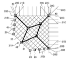
基礎部10は、図1中破線で示すように、平面視で略正方形の枠状に構築されている。この基礎部10の4つの角部のうち、図1中左下側を角部10A、この角部10Aに隣り合う角部を角部10B、角部10Aの対角線上に位置する角部を角部10Cとする。   As shown by a broken line in FIG. 1, the base portion 10 is constructed in a substantially square frame shape in plan view. Of the four corners of the base 10, the lower left side in FIG. 1 is the corner 10A, the corner adjacent to the corner 10A is the corner 10B, and the corner located on the diagonal of the corner 10A is the corner. 10C.

また、屋根架構30は、平面視で菱形状であり、この屋根架構30の4つの角部のうち、図1中左下側の角部を角部30A、この角部30Aに隣り合う角部を角部30B、角部30Aの対角線上に位置する角部を角部30Cとする。   Further, the roof frame 30 has a rhombus shape in plan view. Of the four corners of the roof frame 30, the corner on the lower left side in FIG. 1 is the corner 30A, and the corner adjacent to the corner 30A is the corner. A corner located on a diagonal line between the corner 30B and the corner 30A is defined as a corner 30C.

屋根架構30の角部30Aは、基礎部10の角部10Aの直上に位置している。屋根架構30の角部30Aを支持する外周柱を外周柱20Aとすると、この外周柱20Aは、基礎部10の角部10Aから略鉛直に延びている。
また、この角部30Aつまり外周柱20Aの両側面には、外周柱20に沿って延びる一対の外周ブレース材21Aが配設されている。
The corner 30 </ b> A of the roof frame 30 is located immediately above the corner 10 </ b> A of the foundation 10. When the outer peripheral column that supports the corner portion 30A of the roof frame 30 is the outer peripheral column 20A, the outer peripheral column 20A extends substantially vertically from the corner portion 10A of the base portion 10.
In addition, a pair of outer peripheral brace members 21A extending along the outer peripheral column 20 is disposed on both sides of the corner portion 30A, that is, the outer peripheral column 20A.

屋根架構30の角部30Bは、基礎部10よりも内側に位置している。屋根架構30の角部30Bを支持する3本の外周柱を外周柱20Bとすると、これら外周柱20Bは、基礎部10の角部10B付近から内側に傾斜して延びている。
また、基礎部10の角部10Aから角部10Bまで並んだ外周柱20については、角部10Aから角部10Bに向かうに従って、内側への倒れ(水平面に対する傾斜角度)が大きくなってゆく。
また、この角部30Bつまり外周柱20Bの両側面には、外周柱20、20Bに沿って延びる一対の外周ブレース材21Bが配設されている。
The corner portion 30 </ b> B of the roof frame 30 is located inside the base portion 10. Assuming that the three outer peripheral columns supporting the corner portion 30B of the roof frame 30 are the outer peripheral columns 20B, the outer peripheral columns 20B are inclined and extended inward from the vicinity of the corner portion 10B of the base portion 10.
Moreover, about the outer periphery pillar 20 located in a line from the corner | angular part 10A of the base part 10 to the corner | angular part 10B, as it goes to the corner | angular part 10B from the corner | angular part 10A, the inward fall (inclination angle with respect to a horizontal surface) becomes large.
In addition, a pair of outer peripheral brace members 21B extending along the outer peripheral columns 20 and 20B are disposed on both side surfaces of the corner portion 30B, that is, the outer peripheral column 20B.

屋根架構30の角部30Cは、基礎部10よりも内側に位置している。屋根架構30の角部30Cを支持する3本の外周柱を外周柱20Cとすると、これら外周柱20Cは、基礎部10の角部10C付近から内側に傾斜して延びている。
また、屋根架構30の角部30Bから角部30Cまでの部分は、基礎部10の角部10Bから角部10Cまでの部分に略並行であり、基礎部10の角部10Bから角部10Cまで並んだ外周柱20については、内側への倒れが一定となっている。
The corner 30 </ b> C of the roof frame 30 is located on the inner side of the foundation 10. Assuming that the three outer peripheral columns supporting the corner portions 30C of the roof frame 30 are the outer peripheral columns 20C, the outer peripheral columns 20C are inclined and extended inward from the vicinity of the corner portions 10C of the base portion 10.
Moreover, the part from the corner | angular part 30B of the roof frame 30 to the corner | angular part 30C is substantially parallel to the part from the corner | angular part 10B of the base part 10 to the corner | angular part 10C, and from the corner | angular part 10B of the base part 10 to the corner | angular part 10C. About the outer periphery pillar 20 located in a line, the inward fall is constant.

また、この角部30Cつまり外周柱20Cの両側面には、外周柱20、20Cに沿って延びる一対の外周ブレース材21Cが配設されている。
図1〜図3に示すように、上述の外周柱20B、20Cは、外周柱20Aよりも材軸方向に長く、水平面に対して傾斜した斜め柱である。これら斜め柱である外周柱20B、20Cは、外周梁33で連結されている。
In addition, a pair of outer peripheral brace members 21C extending along the outer peripheral columns 20 and 20C are disposed on both side surfaces of the corner portion 30C, that is, the outer peripheral column 20C.
As shown in FIGS. 1 to 3, the outer peripheral columns 20 </ b> B and 20 </ b> C are oblique columns that are longer than the outer peripheral column 20 </ b> A in the material axis direction and are inclined with respect to the horizontal plane. These outer peripheral columns 20 </ b> B and 20 </ b> C, which are diagonal columns, are connected by an outer peripheral beam 33.

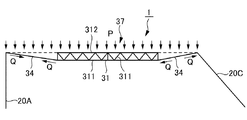
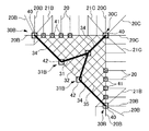
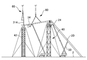
図4は、吊り屋根架構1の主な骨組みを示す模式的な斜視図である。図4では、外周柱20A、20B、20C以外の外周柱20、後述の内側小梁32、および外側小梁35の表示を省略している。
屋根架構30は、平面視で枠状のトラス梁31と、このトラス梁31の上端部同士の間に格子状に架設された内側小梁32と、トラス梁31を囲んで設けられて隣接する外周柱20同士を連結する枠状の外周梁33と、トラス梁31の下端と外周柱20とを連結する4本の連結部材34と、トラス梁31の角部の上端と外周柱20との間に格子状に架設された外側小梁35と、を備える。
ここで、トラス梁31と、このトラス梁31で囲まれた構造体である内側小梁32と、を中央屋根架構37とする。
FIG. 4 is a schematic perspective view showing the main framework of the suspended roof frame 1. In FIG. 4, the display of the outer peripheral columns 20 other than the outer peripheral columns 20 </ b> A, 20 </ b> B, 20 </ b> C, the inner small beam 32 and the outer small beam 35 described later is omitted.
The roof frame 30 is provided adjacent to the frame-shaped truss beam 31 in a plan view, the inner small beam 32 laid in a lattice shape between the upper ends of the truss beam 31, and surrounding the truss beam 31. A frame-shaped outer peripheral beam 33 that connects the outer peripheral columns 20, four connecting members 34 that connect the lower end of the truss beam 31 and the outer peripheral column 20, and an upper end of the corner of the truss beam 31 and the outer peripheral column 20. And an outer small beam 35 laid in a lattice shape between them.
Here, the truss beam 31 and the inner small beam 32 that is a structure surrounded by the truss beam 31 are referred to as a central roof frame 37.

トラス梁31は、側面視でトラス形状であり、平面視で菱形の枠状である。すなわち、トラス梁31は、直線状に延びる4本のトラス部材36を接合して構成される。このトラス梁31の4つの角部つまり4本のトラス部材36同士の接合部分を、角部31A、31B、31Cとする。
各トラス梁31は、図2に示すように、略水平に直線状に延びる下弦材311と、下弦材311の上方に配置されて下弦材311と略平行に直線状に延びる上弦材312と、下弦材311と上弦材312とを連結する斜め材313と、を備える。
The truss beam 31 has a truss shape in a side view and a rhombus frame shape in a plan view. That is, the truss beam 31 is configured by joining four truss members 36 extending linearly. The four corner portions of the truss beam 31, that is, the joint portions between the four truss members 36 are referred to as corner portions 31A, 31B, and 31C.
As shown in FIG. 2, each truss beam 31 includes a lower chord material 311 that extends substantially horizontally and linearly, an upper chord material 312 that is disposed above the lower chord material 311 and extends linearly substantially parallel to the lower chord material 311, And an oblique member 313 that connects the lower chord member 311 and the upper chord member 312.

外周梁33は、平面視で菱形の枠状である。この外周梁33は、所定間隔おきに、外周柱20で支持されている。この外周梁33の4つの角部は、屋根架構の角部30A、30B、30Cとなっている。   The outer circumferential beam 33 has a rhombus frame shape in plan view. The outer peripheral beam 33 is supported by the outer peripheral column 20 at predetermined intervals. The four corners of the outer circumferential beam 33 are corners 30A, 30B, and 30C of the roof frame.

連結部材34は、菱形状のトラス梁31の4つの角部31A、31B、31Cの下弦材311と、外周柱20A、20B、20Cと、を連結する。これにより、外周柱20A、20B、20Cは、連結部材34を介して、トラス梁31を吊り下げ支持している。
これら連結部材34は、トラス梁31の下弦材311および外周梁33にヒンジ接合部38でヒンジ接合されている。ヒンジ接合部38は、略水平でかつ連結部材34の長さ方向に直交する方向に延びるピン341を含んで構成され、連結部材34は、このピン341を回転軸として、トラス梁31の下弦材311および外周梁33に対して回転可能となっている。
The connecting member 34 connects the lower chord members 311 of the four corners 31A, 31B, and 31C of the rhombus-shaped truss beam 31 and the outer peripheral columns 20A, 20B, and 20C. Accordingly, the outer peripheral columns 20A, 20B, and 20C support the truss beam 31 in a suspended manner via the connecting member 34.
These connecting members 34 are hinge-joined to the lower chord material 311 and the outer circumferential beam 33 of the truss beam 31 by a hinge joint portion 38. The hinge joint portion 38 is configured to include a pin 341 that is substantially horizontal and extends in a direction orthogonal to the length direction of the connecting member 34, and the connecting member 34 has a lower chord member of the truss beam 31 with the pin 341 as a rotation axis. 311 and the outer peripheral beam 33 can be rotated.

図1に戻って、内側小梁32は、トラス梁31の上端部同士を連結して互いに略平行に延びる1次小梁321と、1次小梁321同士を連結する2次小梁322と、を備える。
外側小梁35は、外周梁33の上端部とトラス梁31の上端部とを連結して互いに略平行に延びる1次小梁351と、1次小梁351同士を連結する2次小梁352と、を備える。
Returning to FIG. 1, the inner beam 32 includes a primary beam 321 that connects the upper ends of the truss beams 31 and extends substantially parallel to each other, and a secondary beam 322 that connects the primary beams 321. .
The outer small beam 35 connects the upper end portion of the outer circumferential beam 33 and the upper end portion of the truss beam 31 and extends substantially parallel to each other, and the secondary small beam 352 that connects the primary small beams 351 to each other. And comprising.

以上の屋根架構30では、図5および図6に示すように、屋根の自重Pがかかると、トラス梁31の上弦材312には圧縮力が生じ、下弦材311には、引張力が生じる。また、連結部材34には、引張力Qが生じて、外周大梁には、圧縮力Rが生じる。   In the roof frame 30 described above, as shown in FIGS. 5 and 6, when the roof weight P is applied, a compressive force is generated in the upper chord member 312 of the truss beam 31 and a tensile force is generated in the lower chord member 311. Further, a tensile force Q is generated in the connecting member 34, and a compressive force R is generated in the outer peripheral large beam.

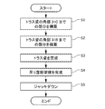
次に、以上の吊り屋根架構1の構築方法について、図7のフローチャートを参照しながら説明する。
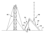
この吊り屋根架構1は、屋根架構30の角部30Cから角部30Aに向かって構築する(図1参照)。
まず、ステップS1では、図8に示すように、屋根架構30の角部30Cからトラス梁31の角部31Cまでの部分を構築する。このとき、建て込んだ外周柱20Cを柱受けベント40で支持するとともに、建て込んだ外周柱20を柱受け支柱41で支持する。また、トラス梁31の角部31Cを構成するトラス梁仕口部314をトラス梁受けベント42で支持する。
Next, the construction method of the above suspended roof frame 1 is demonstrated, referring the flowchart of FIG.
The suspended roof frame 1 is constructed from the corner 30C of the roof frame 30 toward the corner 30A (see FIG. 1).
First, in step S1, as shown in FIG. 8, the part from the corner | angular part 30C of the roof frame 30 to the corner | angular part 31C of the truss beam 31 is constructed | assembled. At this time, the built-in outer peripheral column 20 </ b> C is supported by the column receiving vent 40, and the built-in outer peripheral column 20 is supported by the column receiving column 41. Further, the truss beam joint 314 constituting the corner portion 31 </ b> C of the truss beam 31 is supported by the truss beam receiving vent 42.

具体的には、まず、図9(a)に示すように、柱受けベント40および柱受け支柱41を架設する。次に、外周柱20Cを建て込んで、建て込んだ外周柱20Cを、柱受けベント40で支持する。
次に、図9(b)に示すように、外周柱20Cに隣接する外周柱20を建て込んで、この建て込んだ外周柱20を、柱受け支柱41で支持する。また、建て込んだ外周柱20、20C同士の間に、外周梁33、および外側小梁35を架設することで、構築した架構体の構造的安定性を確保する。
Specifically, first, as shown in FIG. 9A, the column receiving vent 40 and the column receiving column 41 are installed. Next, the outer peripheral column 20 </ b> C is built, and the built outer peripheral column 20 </ b> C is supported by the column receiving vent 40.
Next, as shown in FIG. 9B, the outer peripheral column 20 adjacent to the outer peripheral column 20 </ b> C is built, and the built outer peripheral column 20 is supported by the column receiving column 41. Moreover, the structural stability of the constructed frame is ensured by installing the outer circumferential beam 33 and the outer small beam 35 between the built-in outer circumferential columns 20 and 20C.

次に、図9(c)に示すように、既に建て込んだ外周柱20に隣接する外周柱20を建て込んで、建て込んだ外周柱20を、柱受け支柱41で支持する。また、建て込んだ外周柱20同士の間に、外周ブレース21C、外周梁33、および外側小梁35を架設することで、構築した架構体の構造的安定性を確保する。
このように、屋根架構30の角部30Cから角部30Bに向かって、架構体の構造的安定性を確保しながら、順に外周柱20を建て込んでゆく。
Next, as shown in FIG. 9C, the outer peripheral column 20 adjacent to the already built outer peripheral column 20 is built, and the built outer peripheral column 20 is supported by the column receiving column 41. Moreover, the structural stability of the constructed frame body is ensured by installing the outer peripheral braces 21C, the outer peripheral beams 33, and the outer small beams 35 between the built-in outer peripheral columns 20.
In this way, the outer peripheral pillars 20 are sequentially built from the corner 30C of the roof frame 30 toward the corner 30B while securing the structural stability of the frame.

ステップS2では、図10に示すように、トラス梁31の角部31Bまでの部分を構築する。このとき、外周柱20Bを柱受けベント40で支持するとともに、外周柱20を柱受け支柱41で支持する。また、トラス梁31の角部31Bをトラス梁受けベント42で支持する。
このステップS2では、柱受け支柱41を盛り替えて、その後、屋根架構30の角部30Bに向かって、架構体の構造的安定性を確保しながら、ステップS1と同様に、順に外周柱20を建て込んでゆく。
ここで、柱受けベント40およびトラス梁受けベント42の上端には、図示しない油圧ジャッキを設け、この油圧ジャッキ上に外周柱20Bの頂部およびトラス梁31を載置する。
In step S2, as shown in FIG. 10, the part to the corner | angular part 31B of the truss beam 31 is constructed | assembled. At this time, the outer peripheral column 20B is supported by the column receiving vent 40, and the outer peripheral column 20 is supported by the column receiving column 41. Further, the corner portion 31 </ b> B of the truss beam 31 is supported by the truss beam receiving vent 42.
In this step S2, the column support column 41 is replaced, and then the outer peripheral columns 20 are sequentially arranged in the same manner as in step S1 while ensuring the structural stability of the frame toward the corner 30B of the roof frame 30. Build it in.
Here, a hydraulic jack (not shown) is provided at the upper ends of the column receiving vent 40 and the truss beam receiving vent 42, and the top of the outer peripheral column 20B and the truss beam 31 are placed on the hydraulic jack.

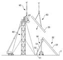
ステップS3では、図11に示すように、トラス梁31を完成させる。このとき、建て込んだ外周柱20を柱受け支柱41で支持する。また、トラス梁31の角部31Aをトラス梁受けベント42で支持する。
具体的には、このステップS3では、柱受け支柱41を盛り替えて、その後、屋根架構30の角部30Bから角部30Aに向かって、架構体の構造的安定性を確保しながら、ステップS1と同様に、順に外周柱20を建て込んでゆく。
In step S3, as shown in FIG. 11, the truss beam 31 is completed. At this time, the built-in outer peripheral column 20 is supported by the column receiving column 41. Further, the corner portion 31 </ b> A of the truss beam 31 is supported by the truss beam receiving vent 42.
Specifically, in this step S3, the column support column 41 is replaced, and then, while securing the structural stability of the frame from the corner 30B of the roof frame 30 toward the corner 30A, step S1 is performed. In the same manner as above, the outer peripheral pillars 20 are built in order.

ステップS4では、残りの外周柱20、20Aを建て込んで、吊り屋根架構1を完成させる。具体的には、このステップS4では、屋根架構30の角部30Aに向かって、架構体の構造的安定性を確保しながら、ステップS1と同様に、順に外周柱20、20Aを建て込んでゆく。   In step S4, the remaining outer peripheral pillars 20 and 20A are built, and the suspended roof frame 1 is completed. Specifically, in this step S4, the outer peripheral columns 20 and 20A are sequentially built in the same manner as in step S1 while securing the structural stability of the frame toward the corner 30A of the roof frame 30. .

ステップS5では、柱受け支柱41を撤去し、その後、柱受けベント40およびトラス梁受けベント42の油圧ジャッキを駆動して、屋根架構30をジャッキダウンする。このとき、屋根架構30を構成する鉄骨部材の下方への変位量が所定の許容変位量以下になるように、ジャッキダウン作業を行う。なお、この屋根架構30の許容変位量は、基本管理値は最小スパン長の1/500であり、極限管理値は最小スパン長の1/300である。   In step S5, the column support column 41 is removed, and then the hydraulic jacks of the column support vent 40 and the truss beam receiving vent 42 are driven to jack down the roof frame 30. At this time, the jackdown operation is performed so that the downward displacement amount of the steel frame member constituting the roof frame 30 is equal to or less than a predetermined allowable displacement amount. As for the allowable displacement amount of the roof frame 30, the basic management value is 1/500 of the minimum span length, and the limit management value is 1/300 of the minimum span length.

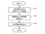
次に、上述のステップS1〜S4において、斜め柱である外周柱20を建て込む手順について、図12のフローチャートを参照しながら説明する。
外周柱20は、三分割されており、直線状に延びる柱脚部22と、この柱脚部22の上から直線状に延びる柱中間部23と、この柱中間部23の上に設けられて外周梁33の一部となる柱頭部24と、を備える(図14参照)。
Next, a procedure for installing the outer peripheral column 20 that is an oblique column in the above-described steps S1 to S4 will be described with reference to the flowchart of FIG.
The outer peripheral column 20 is divided into three parts, and is provided on a column base portion 22 that extends linearly, a column intermediate portion 23 that extends linearly from above the column base portion 22, and the column intermediate portion 23. And a column head 24 to be a part of the outer circumferential beam 33 (see FIG. 14).

まず、ステップS11では、図13に示すように、床面2上に、外周柱20の柱脚部22を仮支持するための方杖部材50を設置するとともに、外周柱20の柱頭部24を仮支持するための柱受けベント40あるいは柱受け支柱41を設置する。
方杖部材50は、床面2上に回転可能に設置されたヒンジ部材51と、このヒンジ部材51の上に設けられて延伸可能なジャッキ52と、このジャッキ52の上に設けられて直線状に延びる支持部材53と、を備える。
この方杖部材50は、柱脚部21を所定位置で支持するものであるため、ヒンジ部材51およびジャッキ52を適宜調整して、方杖部材50の先端の位置を所定の位置に設定しておく。
First, in step S11, as shown in FIG. 13, a cane member 50 for temporarily supporting the column base portion 22 of the outer peripheral column 20 is installed on the floor surface 2 and the column head 24 of the outer peripheral column 20 is mounted. A column receiving vent 40 or a column receiving column 41 for temporary support is installed.
The cane member 50 includes a hinge member 51 that is rotatably installed on the floor surface 2, a jack 52 that is provided on the hinge member 51 and can be extended, and a linear member provided on the jack 52. And a support member 53 extending in the direction.
Since this cane member 50 supports the column base 21 at a predetermined position, the hinge member 51 and the jack 52 are appropriately adjusted to set the position of the tip of the cane member 50 to a predetermined position. .

ステップS12では、図13に示すように、揚重機60で柱脚部22を吊り上げて、所定の位置に建て込む。このとき、柱脚部22の下端部を床面2に取り付けるとともに、柱脚部22の上端部を方杖部材50で仮支持する。これにより、方杖部材50が外周柱20の中間位置を支持することになる。
また、図14に示すように、柱頭部24を揚重機60で吊り上げて、柱受けベント40あるいは柱受け支柱41上に配置する。
In step S12, as shown in FIG. 13, the column base 22 is lifted by the lifting machine 60 and built in a predetermined position. At this time, the lower end portion of the column base portion 22 is attached to the floor surface 2, and the upper end portion of the column base portion 22 is temporarily supported by the cane member 50. Thereby, the cane member 50 supports the intermediate position of the outer peripheral column 20.
Further, as shown in FIG. 14, the column head 24 is lifted by a lifting machine 60 and placed on the column receiving vent 40 or the column receiving column 41.

ステップS13では、図14に示すように、柱中間部23を揚重機60で吊上げて建て込む。これにより、外周柱20を所定位置に建て込むとともに、この外周柱20と外周梁33とを空中で接続する。   In step S <b> 13, as shown in FIG. 14, the column intermediate part 23 is lifted and built by the lifting machine 60. Thus, the outer peripheral column 20 is built in a predetermined position, and the outer peripheral column 20 and the outer peripheral beam 33 are connected in the air.

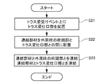
次に、上述のステップS1〜S4において、連結部材34を取り付ける手順について、図15のフローチャートを参照しながら説明する。
初期状態として、図16に示すように、柱受けベント40により、外周柱20の柱頭部24を仮支持しておく。
ステップS21では、トラス梁受けベント42を設置して、トラス梁31の角部31Cを構成するトラス梁仕口部314を、このトラス梁受けベント42上に配置する。
Next, in steps S1 to S4 described above, the procedure for attaching the connecting member 34 will be described with reference to the flowchart of FIG.
As an initial state, as shown in FIG. 16, the column head 24 of the outer peripheral column 20 is temporarily supported by the column receiving vent 40.
In step S <b> 21, the truss beam receiving vent 42 is installed, and the truss beam joint 314 constituting the corner portion 31 </ b> C of the truss beam 31 is disposed on the truss beam receiving vent 42.

ステップS22では、図16に示すように、連結部材34およびトラス梁仕口部314を揚重機60で吊り上げて、これら連結部材34およびトラス梁仕口部314の三次元空間上の位置および姿勢を光波計測して制御しながら、連結部材34の一端を外周柱20の柱頭部24に挿入するとともに、連結部材34の一端をトラス梁仕口部314に挿入する。   In step S22, as shown in FIG. 16, the connecting member 34 and the truss beam joint 314 are lifted by the lifting machine 60, and the positions and postures of the connecting member 34 and the truss beam joint 314 in the three-dimensional space are determined. While measuring and controlling the light wave, one end of the connecting member 34 is inserted into the column head 24 of the outer peripheral column 20 and one end of the connecting member 34 is inserted into the truss beam joint 314.

ステップS23では、ピン341を取り付けて、連結部材34と外周柱20の柱頭部24とを互いに回転可能に連結するとともに、連結部材34とトラス梁仕口部314とを互いに回転可能に連結する。   In step S23, the pin 341 is attached to connect the connecting member 34 and the column head portion 24 of the outer peripheral column 20 to each other so as to be rotatable, and to connect the connecting member 34 and the truss beam joint portion 314 to each other.

すなわち、図17に示すように、トラス梁仕口部314および外周柱20の柱頭部24には、ピン挿通孔342が形成され、連結部材34には、ピン挿通孔343が形成されている。ピン341は、これらピン挿通孔342およびピン挿通孔343に挿通されている。
このとき、図18に示すように、ピン341の先端に、先端に向かうに従って細径となるピン誘導板344を取り付けて、2つのピン挿通孔342、343に、ピン誘導板344の先端から挿通することで、ピン341をピン挿通孔342、343に誘導して挿通する。
That is, as shown in FIG. 17, a pin insertion hole 342 is formed in the truss beam joint 314 and the column head 24 of the outer peripheral column 20, and a pin insertion hole 343 is formed in the connecting member 34. The pin 341 is inserted through the pin insertion hole 342 and the pin insertion hole 343.
At this time, as shown in FIG. 18, a pin guide plate 344 having a diameter decreasing toward the tip is attached to the tip of the pin 341, and the two pin insertion holes 342 and 343 are inserted from the tip of the pin guide plate 344. As a result, the pin 341 is guided and inserted into the pin insertion holes 342 and 343.

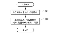
次に、上述のステップS1〜S3において、トラス梁31を構築する手順について、図19のフローチャートを参照しながら説明する。
上述のように。菱形状のトラス梁31は、4つの直線状のトラス部材36を含んで構成される。
ステップS31では、このトラス部材36を地上で地組みする。
ステップS32では、図20に示すように、この地組したトラス部材36を揚重機60で吊り上げて、トラス梁受けベント42間に架設して、トラス梁仕口部314に接合する。このようにして、トラス梁31を空中で組み立てる。
Next, the procedure for constructing the truss beam 31 in steps S1 to S3 described above will be described with reference to the flowchart of FIG.
As mentioned above. The rhombus-shaped truss beam 31 includes four linear truss members 36.
In step S31, the truss member 36 is assembled on the ground.
In step S32, as shown in FIG. 20, the ground truss member 36 is lifted by the lifting machine 60, is laid between the truss beam receiving vents 42, and is joined to the truss beam joint 314. In this way, the truss beam 31 is assembled in the air.

本実施形態によれば、以下のような効果がある。
(1)屋根架構30の中央部に中央屋根架構37を設け、この中央屋根架構37を外周梁33から連結部材34を介して吊り下げ支持して、吊り屋根構造とした。よって、中央屋根架構37のトラス梁31に生じる曲げモーメントは、連結部材34の引張力Qに変換されて外周梁33に伝達されるので、屋根架構30の構成部材に作用する曲げモーメントを低減でき、部材を細径化できる。
また、屋根架構30の中央部のみに枠状のトラス梁31を含む中央屋根架構37を設けて大架構屋根を構築したので、少ない部材数で、大空間を実現できる。
また、屋根架構30の中央部のみにトラス梁31を設置するため、トラス梁31を容易に架設できるから、工期を短縮できる。また、屋根架構30の一部にのみトラス梁31を設けるので、屋根の端部周辺でも、屋根構造1の室内の天井高さを高くできる。
According to this embodiment, there are the following effects.
(1) A central roof frame 37 is provided at the center of the roof frame 30, and the central roof frame 37 is supported by being suspended from the outer circumferential beam 33 via a connecting member 34 to form a suspended roof structure. Therefore, since the bending moment generated in the truss beam 31 of the central roof frame 37 is converted to the tensile force Q of the connecting member 34 and transmitted to the outer circumferential beam 33, the bending moment acting on the constituent members of the roof frame 30 can be reduced. The diameter of the member can be reduced.
Further, since the large roof is constructed by providing the central roof frame 37 including the frame-shaped truss beams 31 only at the center of the roof frame 30, a large space can be realized with a small number of members.
In addition, since the truss beam 31 is installed only in the central portion of the roof frame 30, the truss beam 31 can be easily installed, so the construction period can be shortened. Moreover, since the truss beam 31 is provided only in a part of the roof frame 30, the ceiling height in the room of the roof structure 1 can be increased even around the edge of the roof.

(2)斜め柱である外周柱20を方杖部材50で支持しつつ、外周梁33つまり外周柱20の柱頭部24を柱受けベント40あるいは柱受け支柱41上に配置することで、外周柱20と外周梁33とを本来の位置で接合する。
また、トラス梁仕口314をトラス梁受けベント42上に配置することで、本来の位置に配置し、外周柱20とこのトラス梁仕口部314との間に連結部材34を架設する。このように、外周柱20、トラス梁31、および連結部材34を、本来の位置である空中で接続することで、吊り屋根架構1を高精度で組み立てることができる。
(2) The outer peripheral column 20, that is, the column head 24 of the outer peripheral column 20 is arranged on the column receiving vent 40 or the column receiving column 41 while supporting the outer peripheral column 20 that is an oblique column with the cane member 50. 20 and the outer peripheral beam 33 are joined in their original positions.
Further, the truss beam joint 314 is disposed on the truss beam receiving vent 42 so that the truss beam joint 314 is disposed at an original position, and the connecting member 34 is installed between the outer peripheral column 20 and the truss beam joint 314. Thus, the suspended roof frame 1 can be assembled with high accuracy by connecting the outer peripheral column 20, the truss beam 31, and the connecting member 34 in the air at the original position.

また、屋根架構30の直下に全面に亘って支保工を設けた場合には、大規模な支保工を設ける必要があり、工期が長期化する、という問題がある。しかしながら、本発明によれば、柱受けベント40、柱受け支柱41、およびトラス梁受けベント42により、屋根架構30の一部のみを支持したので、短い工期で吊り屋根架構1を構築できる。   Further, when a support work is provided over the entire surface directly under the roof frame 30, it is necessary to provide a large-scale support work, and there is a problem that the work period is prolonged. However, according to the present invention, since only a part of the roof frame 30 is supported by the column receiving vent 40, the column receiving column 41, and the truss beam receiving vent 42, the suspended roof frame 1 can be constructed in a short construction period.

(3)回転機能を有するヒンジ部材51および延伸機能を有するジャッキ52を備えた方杖部材50を用いて、外周柱20を支持した。よって、1つの方杖部材50で外周柱20の三次元空間上の建込み位置を調整することができる。また、外周柱20の転倒を防止しつつ、外周柱20を所定位置に傾斜させた状態で建て込むことができる。   (3) The outer peripheral column 20 was supported using the cane member 50 provided with the hinge member 51 having a rotating function and the jack 52 having a extending function. Therefore, it is possible to adjust the erected position of the outer peripheral column 20 in the three-dimensional space with one wand member 50. Moreover, it can be built in the state which inclined the outer peripheral pillar 20 to the predetermined position, preventing the outer peripheral pillar 20 from falling.

(4)ピン341の先端にピン誘導板344を取り付けて、このピン誘導板344によりピン341のピン挿通孔342、343への挿入を誘導したので、ピン341とピン挿通孔342、343との隙間が僅かな場合や、ピン挿通孔342、343の相対位置が多少ずれている場合であっても、ピン341を円滑かつ確実にピン挿通孔342、343に挿入できる。   (4) Since the pin guide plate 344 is attached to the tip of the pin 341 and the insertion of the pin 341 into the pin insertion holes 342 and 343 is guided by the pin guide plate 344, the pin 341 and the pin insertion holes 342 and 343 Even when the gap is small or the relative positions of the pin insertion holes 342 and 343 are slightly shifted, the pin 341 can be smoothly and reliably inserted into the pin insertion holes 342 and 343.

なお、本発明は前記実施形態に限定されるものではなく、本発明の目的を達成できる範囲での変形、改良等は本発明に含まれるものである。
また、上記実施形態では、外周柱20を三分割しておき、分割した各構成部材を空中で組み立てたが、これに限らず、外周柱を二分割して空中で組み立ててもよいし、あるいは、外周柱を地上で地組みした後、建て起こしてもよい。
It should be noted that the present invention is not limited to the above-described embodiment, and modifications, improvements, etc. within a scope that can achieve the object of the present invention are included in the present invention.
In the above embodiment, the outer peripheral column 20 is divided into three parts, and the divided components are assembled in the air. However, the present invention is not limited to this, and the outer peripheral column may be divided into two parts and assembled in the air. After the outer peripheral pillars are grounded on the ground, they may be erected.

1…吊り屋根架構 2…床面
10…基礎部 10A、10B、10C…基礎部の角部
20、20A、20B、20C…外周柱(斜め柱)
21A、21B、21C…外周ブレース材
22…柱脚部 23…柱中間部 24…柱頭部
30…屋根架構 30A、30B、30C…屋根架構の角部
31…トラス梁 31A、31B、31C…トラス梁の角部
32…内側小梁 33…外周梁 34…連結部材 35…外側小梁 36…トラス部材
37…中央屋根架構 38…ヒンジ接合部
40…柱受けベント 41…柱受け支柱 42…トラス梁受けベント
50…方杖部材 51…ヒンジ部材 52…ジャッキ 53…支持部材 60…揚重機
311…下弦材 312…上弦材 313…斜め材 314…トラス梁仕口部
321…1次小梁 322…2次小梁 341…ピン
342、343…ピン挿通孔
344…ピン誘導板 351…1次小梁 352…2次小梁
DESCRIPTION OF SYMBOLS 1 ... Suspended roof frame 2 ... Floor surface 10 ... Base part 10A, 10B, 10C ... Corner | angular part 20, 20A, 20B, 20C ... Peripheral column (diagonal column)
21A, 21B, 21C ... outer peripheral brace material 22 ... column base 23 ... column intermediate part 24 ... column head 30 ... roof frame 30A, 30B, 30C ... corner of roof frame 31 ... truss beam 31A, 31B, 31C ... truss beam Corner portion 32 ... inner beam 33 ... outer beam 34 ... connecting member 35 ... outer beam 36 ... truss member 37 ... central roof frame 38 ... hinge joint 40 ... column support vent 41 ... column support column 42 ... truss beam support Vent 50 ... Cane member 51 ... Hinge member 52 ... Jack 53 ... Support member 60 ... Weighting machine 311 ... Lower chord material 312 ... Upper chord material 313 ... Diagonal material 314 ... Truss beam joint 321 ... Primary beam 322 ... Secondary Small beam 341 ... Pin 342, 343 ... Pin insertion hole
344 ... Pin guide plate 351 ... Primary beam 352 ... Secondary beam

Claims (3)

吊り屋根架構の構築方法であって、
当該吊り屋根架構は、複数の外周柱と、当該外周柱同士を連結する外周梁と、平面視で四角形枠状に配設されたトラス梁と、前記外周柱と前記トラス梁とを連結する連結部材と、を備え、
前記外周柱を建て込んで、その後、当該外周柱と前記外周梁とを空中で接合する工程と、
支保工を設置して、当該支保工上に、前記トラス梁の一部であるトラス梁仕口部を配置する工程と、
前記連結部材を、前記外周柱と前記トラス梁仕口部との間に架設する工程と、
前記トラス梁を空中で組み立てる工程と、を備えることを特徴とする吊り屋根架構の構築方法。
A method for constructing a suspended roof frame,
The suspended roof frame includes a plurality of outer peripheral columns, an outer peripheral beam connecting the outer peripheral columns, a truss beam arranged in a rectangular frame shape in plan view, and a connection connecting the outer peripheral column and the truss beam. A member, and
Building the outer peripheral column, and then joining the outer peripheral column and the outer peripheral beam in the air;
Installing a support work and placing a truss beam joint that is a part of the truss beam on the support work; and
Laying the connecting member between the outer peripheral column and the truss beam joint;
And a step of assembling the truss beam in the air.
前記外周柱のうち少なくとも2本は、斜め柱であり、
当該斜め柱を建て込む工程では、床面上に回転可能に設置されたヒンジ部材と、当該ヒンジ部材の上に設けられて延伸可能なジャッキと、当該ジャッキの上に設けられた支持部材と、を備える方杖部材を用意し、
前記斜め柱の下端部を床面上に取り付けるとともに、当該斜め柱の中間部を前記方杖部材で支持することで、前記斜め柱を所定の位置に建て込むことを特徴とする請求項1に記載の吊り屋根架構の構築方法。
At least two of the outer peripheral columns are diagonal columns,
In the step of building the diagonal pillar, a hinge member rotatably installed on the floor, a jack provided on the hinge member and extendable, a support member provided on the jack, Prepare a staff member with
2. The diagonal column is built in a predetermined position by attaching a lower end portion of the diagonal column on the floor and supporting an intermediate portion of the diagonal column with the staff member. The construction method of the suspended roof frame of description.
前記トラス梁仕口部と前記連結部材との連結部分、および、前記外周柱と前記連結部材との連結部分には、それぞれ、ピン挿通孔が形成され、
前記連結部材を前記斜め柱と前記トラス梁仕口部との間に架設する工程では、ピンの先端に、先端に向かうに従って細径となるピン誘導板を取り付けて、
当該ピン誘導板の先端を前記2つのピン挿通孔に挿通することで、前記ピンを前記2つのピン挿通孔に誘導して挿通することを特徴とする請求項1に記載の吊り屋根架構の構築方法。
A pin insertion hole is formed in each of the connecting portion between the truss beam joint and the connecting member, and the connecting portion between the outer peripheral column and the connecting member,
In the step of laying the connecting member between the oblique column and the truss beam joint part, a pin guide plate having a diameter decreasing toward the tip is attached to the tip of the pin,
The construction of a suspended roof frame according to claim 1, wherein the pin is guided and inserted into the two pin insertion holes by inserting the tip of the pin guide plate into the two pin insertion holes. Method.
JP2016069847A 2016-03-31 2016-03-31 How to construct a suspended roof frame Pending JP2017179934A (en)

Priority Applications (1)

Application Number Priority Date Filing Date Title
JP2016069847A JP2017179934A (en) 2016-03-31 2016-03-31 How to construct a suspended roof frame

Applications Claiming Priority (1)

Application Number Priority Date Filing Date Title
JP2016069847A JP2017179934A (en) 2016-03-31 2016-03-31 How to construct a suspended roof frame

Publications (1)

Publication Number Publication Date
JP2017179934A true JP2017179934A (en) 2017-10-05

Family

ID=60005542

Family Applications (1)

Application Number Title Priority Date Filing Date
JP2016069847A Pending JP2017179934A (en) 2016-03-31 2016-03-31 How to construct a suspended roof frame

Country Status (1)

Country Link
JP (1) JP2017179934A (en)

Cited By (2)

* Cited by examiner, † Cited by third party
Publication number Priority date Publication date Assignee Title
CN111042539A (en) * 2019-12-02 2020-04-21 中建钢构有限公司 Single-point support installation construction method for large-span steel structure truss
CN116446651A (en) * 2023-04-11 2023-07-18 中建八局发展建设有限公司 An installation auxiliary device and an installation positioning method for a special-shaped polygonal aluminum plate

Cited By (3)

* Cited by examiner, † Cited by third party
Publication number Priority date Publication date Assignee Title
CN111042539A (en) * 2019-12-02 2020-04-21 中建钢构有限公司 Single-point support installation construction method for large-span steel structure truss
CN111042539B (en) * 2019-12-02 2022-06-24 中建钢构工程有限公司 Single-point support installation construction method for large-span steel structure truss
CN116446651A (en) * 2023-04-11 2023-07-18 中建八局发展建设有限公司 An installation auxiliary device and an installation positioning method for a special-shaped polygonal aluminum plate

Similar Documents

Publication Publication Date Title
JP6424075B2 (en) REINFORCED CONCRETE COLUMN STEEL BEAM JOINTING MEMBER, ITS MANUFACTURING METHOD, AND BUILDING CONSTRUCTION METHOD
CN103410353B (en) Garage steel framework and mounting process
JP6374363B2 (en) Building structure, building and construction method
JP2017179934A (en) How to construct a suspended roof frame
JP2012036584A (en) Arrangement method of reinforced concrete column
JP2903945B2 (en) Large span structure and construction method thereof
JP3179138U (en) Scaffolding support for leg head construction
JP6849491B2 (en) Exposed column base structure of steel columns and its construction method
JP5711097B2 (en) Column structure and construction method
JP6391375B2 (en) Anchor device
JP6755102B2 (en) Construction method of the outer wall panel base and outer wall material
JP6543491B2 (en) Building stairway structure
JP7266460B2 (en) Temporary gantry for foundation frame of climbing crane
JP6718713B2 (en) Roof structure
JP6917720B2 (en) How to build a composite suspended structure
JP6464069B2 (en) Templates, template sets and reinforcement methods
JP2022101717A (en) Curing system in demolishing building, and demolition method of building to be demolished
JP4772428B2 (en) Method for assembling roof truss members
JP2021032034A (en) building
JP4825146B2 (en) How to set up a temporary structure
JP2793053B2 (en) Building construction method
CN112647647B (en) A special-shaped column steel bar assembly structure and construction method thereof
JP2020056234A (en) Building construction method
JP2004116285A (en) Frame structure
JP5551095B2 (en) Support device and method for manufacturing external pillar for house