JP2017180331A - Two-tank oil pan for internal combustion engine - Google Patents
Two-tank oil pan for internal combustion engine Download PDFInfo
- Publication number
- JP2017180331A JP2017180331A JP2016069566A JP2016069566A JP2017180331A JP 2017180331 A JP2017180331 A JP 2017180331A JP 2016069566 A JP2016069566 A JP 2016069566A JP 2016069566 A JP2016069566 A JP 2016069566A JP 2017180331 A JP2017180331 A JP 2017180331A
- Authority
- JP
- Japan
- Prior art keywords
- oil
- recess
- tank
- strainer
- oil pan
- Prior art date
- Legal status (The legal status is an assumption and is not a legal conclusion. Google has not performed a legal analysis and makes no representation as to the accuracy of the status listed.)
- Granted
Links
Images


Landscapes
- Lubrication Details And Ventilation Of Internal Combustion Engines (AREA)
Abstract
Description
本願発明は、内燃機関に使用する二槽式オイルパンに関するもので、特に、車両用内燃機関に使用するオイルパンを好適な対象にしている。 The present invention relates to a two-tank oil pan for use in an internal combustion engine, and is particularly suitable for an oil pan used in a vehicle internal combustion engine.
内燃機関において、オイルの早期昇温を図るためオイルパンを二槽式に構成することは広く行われており、この二槽式のオイルパンでは、ストレーナは内槽に浸漬している。そして、単層式と二槽式とに限らず、オイルパンで発生する問題の一つとして、オイルパンの底部に水滴が溜まって低温環境下で氷結し、この氷がストレーナのフィルターに詰まって油量不足を招くことがある。 2. Description of the Related Art In an internal combustion engine, it is widely performed to configure an oil pan in a two-tank type in order to increase the temperature of oil early. In this two-tank type oil pan, a strainer is immersed in an inner tank. One problem that occurs with oil pans, not limited to single-layer and double-tank types, is that water drops accumulate at the bottom of the oil pan and freeze in a low-temperature environment, and this ice clogs the strainer filter. Oil shortage may be caused.
この点について特許文献1には、単層式のオイルパンにおいて、その底部に水滴が溜まる深い滞留部を形成して、この滞留部をメッシュで覆うことが開示されている。この特許文献1では、水滴は深い滞留部に集められて、水滴が氷結しても、ストレーナに吸い込まれることがメッシュで阻止される。
In this regard,
さて、車両用内燃機関のオイルパンでは、車両の傾きや発進、停止等によって油面が大きく変動する。そこで、オイルパンの底の一部に、油面が変動しても常にオイルで満たされている凹部を形成し、この凹部からストレーナでオイルを吸い込むように構成していることが多い。 Now, in an oil pan of an internal combustion engine for a vehicle, the oil level greatly fluctuates due to the inclination, start, stop, etc. of the vehicle. Therefore, a recess that is always filled with oil is formed in a part of the bottom of the oil pan even when the oil level fluctuates, and the oil is often sucked from the recess by a strainer.
しかるに、特許文献1では、滞留部が最も深くなっており、ストレーナの吸い込みは滞留部より高くなっているため、車両用に適用すると、油面の変動によってストレーナがオイルを吸わない状態が表れ兼ねないという問題があった。また、メッシュを設けると、それだけコストが嵩むという問題もある。
However, in
更に、特許文献1は、オイルが滞留部に流れ込む前に氷結すると、ストレーナへの吸い込みを阻止できない問題や、水滴を隔離することはできず、油温の上昇によって氷から水滴に戻ると、オイルの動きによってメッシュを透過して滞留部の外に戻されるという現象が生じるおそれがあり、抜本的な対策と言い難い。
Furthermore,
本願発明は、このような現状を改善すべく成されたものであり、二槽式オイルパンの構造を利用して、水滴の問題を無くそうとするものである。 The present invention has been made to improve such a current situation, and intends to eliminate the problem of water droplets by utilizing the structure of a two-tank oil pan.
本願発明は、外槽と内槽とを有しており、前記内槽に、ストレーナによる吸い込み部になる凹部が形成されている二槽式はオイルパンにおいて、
前記内槽に、一端は前記凹部に連通して他端は前記凹部から離れている細い連通溝を、その底面が前記凹部の底面と同じ程度の高さかそれより低くなるようにして形成し、前記連通溝の底部に、オイル中に発生した水滴が通過し得る大きさの小穴を空けている。
The present invention has an outer tub and an inner tub, and in the inner tub, a two-tank type in which a recess to be a suction portion by a strainer is formed is an oil pan.
In the inner tub, a narrow communication groove having one end communicating with the recess and the other end separated from the recess is formed such that the bottom surface is as high as or lower than the bottom surface of the recess, A small hole having a size through which water droplets generated in the oil can pass is formed at the bottom of the communication groove.
本願発明において、小穴は1つの連通溝に複数空けること可能であるが、通常は1つで足りる(外槽からのオイルの流入を抑制するためには、必要最小限度が好ましい。)。連通溝を複数形成して、各連通溝に小穴を形成することも可能である。また、小穴を連通溝のどこに空けるかについては、外槽のオイルの吸引防止のためには、小穴は連通溝の他端部に空けるのが確実であるが、外槽からのオイルの吸い上げが無ければ、一端と他端との間の適宜部位に空けてもよい。 In the present invention, it is possible to make a plurality of small holes in one communication groove, but one is usually sufficient (in order to suppress the inflow of oil from the outer tank, the necessary minimum is preferable). It is also possible to form a plurality of communicating grooves and form small holes in each communicating groove. In addition, as to where the small hole is to be opened in the communication groove, it is certain that the small hole will be opened at the other end of the communication groove in order to prevent the oil from being sucked from the outer tank, but the oil from the outer tank is not sucked up. If there is not, you may leave in the suitable part between one end and the other end.
本願発明では、ストレーナの先端が臨んでいる凹部は深くなっているため、オイルパンが傾いたり、オイルパン内でオイルが揺動したりしても、常にストレーナの先端を浸漬させた状態に保持できる。従って、潤滑やオイルジェット冷却のような機能を的確に発揮できる。 In the present invention, since the concave portion where the tip of the strainer faces is deep, even if the oil pan is tilted or the oil swings in the oil pan, the strainer tip is always immersed. it can. Therefore, functions such as lubrication and oil jet cooling can be exhibited accurately.
また、連通溝は細幅であるため、オイルパンが揺動してもオイルが連通溝から凹部の外側に大きく移動するようなことはなくて、凹部のオイルを溜めておくことができる。従って、凹部のオイルが減ってストレーナからエアを吸い込むようなことはない。つまり、常にオイルで満たされているという凹部の機能は損なわれない。 Further, since the communication groove is narrow, oil does not move greatly from the communication groove to the outside of the recess even when the oil pan swings, and the oil in the recess can be stored. Therefore, the oil in the recess is not reduced and air is not sucked from the strainer. That is, the function of the recess that is always filled with oil is not impaired.
更に、小穴は小径でしかも凹部の外側に位置しているため、ストレーナの吸引力が小穴に作用することを防止できる。従って、外槽のオイルが小穴から内槽に吸引されることも防止できる。このため、内槽のオイルを循環させてオイルを早期昇温させる機能は損なわれておらず、早期暖機に支障はない。 Furthermore, since the small hole has a small diameter and is positioned outside the recess, it is possible to prevent the suction force of the strainer from acting on the small hole. Therefore, it is possible to prevent the oil in the outer tank from being sucked into the inner tank from the small hole. For this reason, the function of circulating the oil in the inner tank to raise the temperature of the oil early is not impaired, and there is no hindrance to the early warm-up.
そして、水分がオイル中で凝集して生じた水滴(或いは氷粒)は、オイルの流れに載って浮遊しながら凹部に流入する。従って、凹部の底に至った水滴は、オイルの揺動等によって凹部の外周側に押されるような挙動をとるため、凹部の底で揺れ動いているうちに連通溝に入り込み、そして、オイルの動きに押されて連通溝の他端に向けて移動して行き、やがて小穴を通過して外槽に入り込む。 Then, water droplets (or ice particles) generated by condensation of water in the oil flow into the recesses while floating on the oil flow. Therefore, the water droplets that reach the bottom of the concave portion behave to be pushed to the outer peripheral side of the concave portion due to oil swinging or the like, and therefore enter the communication groove while swinging at the bottom of the concave portion, and the movement of the oil Is pushed toward the other end of the communication groove and eventually passes through the small hole and enters the outer tub.
そして、外槽のオイルはストレーナによる吸引作用は受けないため、水滴が氷結してもストレーナのフィルターが詰まるようなことは無い。従って、内槽に水滴が発生しても、その悪影響を防止できる。そして、水滴を内槽から排除するものであるから、内槽に水滴が徐々に増えていくようなことは無くて、抜本的な対策になっている。しかも、連通溝は内槽の一部として製造されるから、コストも抑制できる。 Since the oil in the outer tank is not subjected to the suction action by the strainer, the strainer filter is not clogged even if water droplets freeze. Therefore, even if water droplets are generated in the inner tank, the adverse effects can be prevented. And since a water droplet is excluded from an inner tank, there is no case where a water drop gradually increases in an inner tank, and it is a radical measure. And since a communicating groove is manufactured as a part of inner tank, cost can also be suppressed.
外槽の底には、オイル交換時にオイルを抜くためのドレン穴が設けられているが、水滴が通過する小穴をドレン穴の上に位置させておくと、外槽に移行した水滴をオイル交換時に抜き取ることができる利点がある。 A drain hole is provided at the bottom of the outer tank to drain the oil when changing the oil. If a small hole through which water drops pass is positioned above the drain hole, the water drops transferred to the outer tank are replaced with oil. There is an advantage that can be extracted from time to time.
次に、本願発明の実施形態を図面に基づいて説明する。まず、図1〜4に示す第1実施形態を説明する。オイルパンは、合成樹脂製の内槽1と、アルミダイキャスト品や板金加工品等の金属製の外槽2とから成っている。外槽2の上端には、シリンダブロックに固定されるフランジ3が形成されている。内槽1は外槽2にビスで固定されている。このため、内槽1には、外槽2のボス部(図示せず)に重なる支持座4が、周方向に沿って飛び飛びに形成されている。
Next, an embodiment of the present invention will be described with reference to the drawings. First, the first embodiment shown in FIGS. The oil pan is composed of an
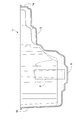
内槽1と外槽2とは全体に亙って深く形成されている訳ではなく、内槽1について見ると、図2のとおり、底のうち一方の短辺1aの側の略半分弱は、オイルが溜まらない浅底部5になって、他方の短辺1bの側の略半分強が、オイルが溜る深底部6になっている。
The
そして、深底部6のうち、浅底部5に寄った部位でかつ長手中心線7からやや外れた部位に、ストレーナ8による吸い込み部となる凹部9が、下向きに凹んだ状態に形成されている。凹部9は、鉛直面で切った断面が逆台形になっているが、四角形や半円形などに形成することも可能である。
In the
図3示すにように、内槽1の深底部6は、一方の長手側面1cの側から他方の長手側面1dの側に深さが深くなる基本形状であり、凹部9は、長手中心線7から一方の長手側面1cにやや寄せて形成されている。
As shown in FIG. 3, the
そして、内槽1に、実線で示す第1連通溝10と、一点鎖線で示す第2連通溝11とを形成し、各連通溝10,11の先端に小穴12を空けている。第1連通溝10と第2連通溝11とは、いずれか一方を選択して設けることも可能であるし、両方を設けることも可能である。
And the 1st communicating
両連通溝10,11の溝幅は数mmと狭くなっており、かつ、底面は、一端は凹部9の底面と略同じ高さで、凹部9から他端に遠ざかるに従って僅かに低くなるように、水平に対して傾斜している。そして、連通溝10,11の先端に小穴12を空けている。連通溝10,11の底は、凹部9の底と同じ高さで水平に設定してもよい。
The groove widths of both the
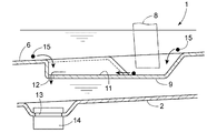
外槽2のうち小穴12の下方には、オイル交換時にオイルを抜き取るドレン穴13が位置している。ドレン穴13は、プラグ14で塞がれている。図3と図4との両方にドレン穴13を表示しているが、両連通溝10,11を併設する場合は、ドレン穴13はいずれか一方だけになる。
In the
以上の構成において、油中に水分が浮遊していると、水分は互いに凝集して水滴15となり、水滴15は最も低い凹部9に移動してくる。そして、凹部9に至った水滴15は、オイルの揺れに載って、凹部9の外周に当たったり、凹部9の縁に沿って移動したりして、そのうちに連通溝10,11に入り込む。連通溝10,11に入り込んだ後は、オイルの揺動による押し作用によって奥に押されていき、他端に至って小穴12から外槽2に移動する。
In the above configuration, when water is floating in the oil, the water aggregates to form
外槽2に至った水滴15が内槽1に戻ることはないため、内槽1において水滴15が氷結したり溶けたりを繰り返すことはない。このため、ストレーナ8のフィルターに水滴15が付着してオイルの吸い上げ量が低下するようなことはない。なお、連通溝10,11には、凹部9の外側からも水滴15が流入可能である。
Since the water drops 15 reaching the
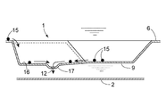
上記の第1実施形態では、小穴12を連通溝10,11の終端(他端)に設けたが、図5に示す第2実施形態では、連通溝16の一端と他端との間の略中間部に下向き膨出部17を形成して、下向き膨出部17に小穴12を空けている。水滴15が下向き膨出部17に落ち込むと、水滴15が凹部9に戻ることはないため、水滴15の無害化を確実化できる。
In the first embodiment, the
連通溝は1本又は2本に限らないのであり、3本以上を放射状に形成することも可能である。深底部6の底面のうち凹部9の外側の部位に、水滴15が連通溝に向かうようにガイドするリブを設けることも可能である。連通溝は直線状には限らず、平面視で曲がっていてもよい。
The communication groove is not limited to one or two, and three or more communication grooves can be formed radially. It is also possible to provide a rib for guiding the
本願発明は、二槽式オイルパンに具体化できる。従って、産業上利用できる。 The present invention can be embodied in a two-tank oil pan. Therefore, it can be used industrially.
1 内槽
2 外槽
6 深底部
9 凹部
10,11,16 連通溝
12 小穴
13 外槽のドレン穴
15 水滴
DESCRIPTION OF
Claims (1)
前記内槽に、一端は前記凹部に連通して他端は前記凹部から離れている細い連通溝を、その底面が前記凹部の底面と同じ程度の高さかそれより低くなるようにして形成し、前記連通溝の底部に、オイル中に発生した水滴が通過し得る大きさの小穴を空けている、
内燃機関の二槽式オイルパン。 It has an outer tub and an inner tub, and the inner tub has a recess formed as a suction portion by a strainer,
In the inner tub, a narrow communication groove having one end communicating with the recess and the other end separated from the recess is formed such that the bottom surface is as high as or lower than the bottom surface of the recess, A small hole having a size through which water droplets generated in oil can pass is formed at the bottom of the communication groove.
Two-tank oil pan for internal combustion engines.
Priority Applications (1)
| Application Number | Priority Date | Filing Date | Title |
|---|---|---|---|
| JP2016069566A JP6654084B2 (en) | 2016-03-30 | 2016-03-30 | Two-tank oil pan for internal combustion engine |
Applications Claiming Priority (1)
| Application Number | Priority Date | Filing Date | Title |
|---|---|---|---|
| JP2016069566A JP6654084B2 (en) | 2016-03-30 | 2016-03-30 | Two-tank oil pan for internal combustion engine |
Publications (2)
| Publication Number | Publication Date |
|---|---|
| JP2017180331A true JP2017180331A (en) | 2017-10-05 |
| JP6654084B2 JP6654084B2 (en) | 2020-02-26 |
Family
ID=60006861
Family Applications (1)
| Application Number | Title | Priority Date | Filing Date |
|---|---|---|---|
| JP2016069566A Active JP6654084B2 (en) | 2016-03-30 | 2016-03-30 | Two-tank oil pan for internal combustion engine |
Country Status (1)
| Country | Link |
|---|---|
| JP (1) | JP6654084B2 (en) |
Citations (8)
| Publication number | Priority date | Publication date | Assignee | Title |
|---|---|---|---|---|
| JPS5340143U (en) * | 1976-09-10 | 1978-04-07 | ||
| JPH024915U (en) * | 1988-06-22 | 1990-01-12 | ||
| US20030029412A1 (en) * | 2001-07-25 | 2003-02-13 | Toyota Jidosha Kabushiki Kaisha | Oil pan structure and oil pan separator |
| WO2006046401A1 (en) * | 2004-10-05 | 2006-05-04 | Toyota Jidosha Kabushiki Kaisha | Oil pan and lubrication device |
| JP2006125201A (en) * | 2004-10-26 | 2006-05-18 | Toyota Motor Corp | Two tank oil pan |
| JP2006249958A (en) * | 2005-03-09 | 2006-09-21 | Toyota Motor Corp | Lubricating device and engine |
| JP2010255516A (en) * | 2009-04-24 | 2010-11-11 | Daikyonishikawa Corp | Oil pan |
| JP2013064389A (en) * | 2011-09-20 | 2013-04-11 | Pacific Ind Co Ltd | Inner pan with baffle plate |
-
2016
- 2016-03-30 JP JP2016069566A patent/JP6654084B2/en active Active
Patent Citations (10)
| Publication number | Priority date | Publication date | Assignee | Title |
|---|---|---|---|---|
| JPS5340143U (en) * | 1976-09-10 | 1978-04-07 | ||
| JPH024915U (en) * | 1988-06-22 | 1990-01-12 | ||
| US20030029412A1 (en) * | 2001-07-25 | 2003-02-13 | Toyota Jidosha Kabushiki Kaisha | Oil pan structure and oil pan separator |
| JP2003222012A (en) * | 2001-07-25 | 2003-08-08 | Toyota Motor Corp | Oil pan structure and oil pan separator |
| WO2006046401A1 (en) * | 2004-10-05 | 2006-05-04 | Toyota Jidosha Kabushiki Kaisha | Oil pan and lubrication device |
| US20120037456A1 (en) * | 2004-10-05 | 2012-02-16 | Toyota Jidosha Kabushiki Kaisha | Oil pan and lubricating device |
| JP2006125201A (en) * | 2004-10-26 | 2006-05-18 | Toyota Motor Corp | Two tank oil pan |
| JP2006249958A (en) * | 2005-03-09 | 2006-09-21 | Toyota Motor Corp | Lubricating device and engine |
| JP2010255516A (en) * | 2009-04-24 | 2010-11-11 | Daikyonishikawa Corp | Oil pan |
| JP2013064389A (en) * | 2011-09-20 | 2013-04-11 | Pacific Ind Co Ltd | Inner pan with baffle plate |
Also Published As
| Publication number | Publication date |
|---|---|
| JP6654084B2 (en) | 2020-02-26 |
Similar Documents
| Publication | Publication Date | Title |
|---|---|---|
| US7748500B2 (en) | Oil pan for internal combustion engine | |
| KR100849050B1 (en) | Oil pan and lubrication device | |
| JP6021826B2 (en) | Piston for internal combustion engine | |
| JP2014508886A (en) | Piston for internal combustion engine | |
| JP5397077B2 (en) | Engine oil return device | |
| CN101680317B (en) | Oil pan structure | |
| JP2017180331A (en) | Two-tank oil pan for internal combustion engine | |
| US20060070943A1 (en) | Oil strainer for automatic transmission | |
| JP4483910B2 (en) | Oil pan structure | |
| JP6308841B2 (en) | Tank structure | |
| CN105464750B (en) | Oil and gas separation type cylinder head cover assembly and its engine | |
| JP2012117480A (en) | Oil pan structure for vehicle engine | |
| JP6709244B2 (en) | Lubricating device for automobile internal combustion engine | |
| CN105201681A (en) | Cover | |
| CN205089475U (en) | Shroud | |
| CN204663615U (en) | Motor bottom | |
| JP2015194144A (en) | Oil pan | |
| JP2007138792A (en) | Lubrication device and oil pan | |
| JP2008208736A (en) | Oil circulation device | |
| JP6584790B2 (en) | Oil strainer for vehicles | |
| JP6315822B2 (en) | Two tank oil pan inner pan | |
| JP2020148121A (en) | Engine piston lubricator | |
| JP4872933B2 (en) | Oil pan | |
| JPS6034731Y2 (en) | Jump type lubrication device for vertical engine | |
| JP6294811B2 (en) | Inner pan with baffle plate |
Legal Events
| Date | Code | Title | Description |
|---|---|---|---|
| A621 | Written request for application examination |
Free format text: JAPANESE INTERMEDIATE CODE: A621 Effective date: 20190225 |
|
| A711 | Notification of change in applicant |
Free format text: JAPANESE INTERMEDIATE CODE: A711 Effective date: 20190225 |
|
| A521 | Request for written amendment filed |
Free format text: JAPANESE INTERMEDIATE CODE: A821 Effective date: 20190225 |
|
| A977 | Report on retrieval |
Free format text: JAPANESE INTERMEDIATE CODE: A971007 Effective date: 20191023 |
|
| A131 | Notification of reasons for refusal |
Free format text: JAPANESE INTERMEDIATE CODE: A131 Effective date: 20191030 |
|
| A521 | Request for written amendment filed |
Free format text: JAPANESE INTERMEDIATE CODE: A523 Effective date: 20191217 |
|
| TRDD | Decision of grant or rejection written | ||
| A01 | Written decision to grant a patent or to grant a registration (utility model) |
Free format text: JAPANESE INTERMEDIATE CODE: A01 Effective date: 20200108 |
|
| A61 | First payment of annual fees (during grant procedure) |
Free format text: JAPANESE INTERMEDIATE CODE: A61 Effective date: 20200129 |
|
| R150 | Certificate of patent or registration of utility model |
Ref document number: 6654084 Country of ref document: JP Free format text: JAPANESE INTERMEDIATE CODE: R150 |
|
| R250 | Receipt of annual fees |
Free format text: JAPANESE INTERMEDIATE CODE: R250 |
|
| R250 | Receipt of annual fees |
Free format text: JAPANESE INTERMEDIATE CODE: R250 |
|
| R250 | Receipt of annual fees |
Free format text: JAPANESE INTERMEDIATE CODE: R250 |
|
| R250 | Receipt of annual fees |
Free format text: JAPANESE INTERMEDIATE CODE: R250 |