JP2017180532A - 緩衝装置 - Google Patents
緩衝装置 Download PDFInfo
- Publication number
- JP2017180532A JP2017180532A JP2016064370A JP2016064370A JP2017180532A JP 2017180532 A JP2017180532 A JP 2017180532A JP 2016064370 A JP2016064370 A JP 2016064370A JP 2016064370 A JP2016064370 A JP 2016064370A JP 2017180532 A JP2017180532 A JP 2017180532A
- Authority
- JP
- Japan
- Prior art keywords
- shock absorber
- spring member
- bending spring
- holes
- shock
- Prior art date
- Legal status (The legal status is an assumption and is not a legal conclusion. Google has not performed a legal analysis and makes no representation as to the accuracy of the status listed.)
- Granted
Links
Images


Landscapes
- Vibration Prevention Devices (AREA)
- Springs (AREA)
Abstract
Description
制振対象物への振動伝達を緩衝する緩衝装置であって、
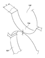
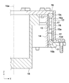
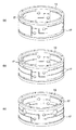
複数の弾性変形部を有する筒形の撓みばね部材によって外側部材及び内側部材の間を連結し、更に前記外側部材及び前記内側部材の間に緩衝部材を配設したことにより、前記外側部材及び前記内側部材の間で伝達される振動を減衰することを特徴とする緩衝装置が提供される。
イ 個々の搭載品に対して寸法が嵩張らずFitするものであること。
ロ 減衰が望まれる軸に関しては150Hz以下の固有値で減衰比が0.1以上であること。
ハ 特に光学系では減衰が望まれる軸と直行方向に関しては剛であること。
ニ ヒステレシスがないこと、
が要求される。
Claims (11)
- 制振対象物への振動伝達を緩衝する緩衝装置であって、
複数の弾性変形部を有する筒形の撓みばね部材によって外側部材及び内側部材の間を連結し、更に前記外側部材及び前記内側部材の間に緩衝部材を配設したことにより、前記外側部材及び前記内側部材の間で伝達される振動を減衰することを特徴とする緩衝装置。 - 前記撓みばね部材と、前記外側部材と、前記内側部材とが円筒形状を有することを特徴とする請求項1に記載の緩衝装置。
- 前記撓みばね部材と前記外側部材とを、前記撓みばね部材の軸方向で前記撓みばね部材の一方端部において連結し、前記撓みばね部材と前記内側部材とを、前記軸方向で前記撓みばね部材の他方端部において連結したことを特徴とする請求項2に記載の緩衝装置。
- 前記緩衝部材は、前記外側部材と前記内側部材との間の隙間に配置されたことを特徴とする請求項2に記載の緩衝装置。
- 前記緩衝部材は、前記撓みばね部材の周方向に複数配置されたことを特徴とする請求項4に記載の緩衝装置。
- 前記緩衝部材は、帯状をなし、前記撓みばね部材の外周面または内周面の少なくともいずれか一方に固定されたことを特徴とする請求項5に記載の緩衝装置。
- 前記緩衝部材は、少なくとも前記内側部材と前記撓みばね部材との間に配置されたことを特徴とする請求項5に記載の緩衝装置。
- 前記緩衝部材は、粘弾性体であることを特徴とする請求項1に記載の緩衝装置。
- 各弾性変形部は、前記撓みばね部材の軸方向において互いに隣接し、前記撓みばね部材の周壁を貫通して形成された二つの円形貫通孔の組により形成されたことを特徴とする請求項1に記載の緩衝装置。
- 前記円形貫通孔には、前記周壁の周方向に沿って延びるスリットが接続されていることを特徴とする請求項9に記載の緩衝装置。
- 前記スリットは、隣接する前記円形貫通孔を結ぶクランク形状のスリットと、隣接する前記円形貫通孔を結ばずに前記円形貫通孔から独立して設けられた直線形状のスリットとを有することを特徴とする請求項10に記載の緩衝装置。
Priority Applications (1)
| Application Number | Priority Date | Filing Date | Title |
|---|---|---|---|
| JP2016064370A JP6786236B2 (ja) | 2016-03-28 | 2016-03-28 | 緩衝装置 |
Applications Claiming Priority (1)
| Application Number | Priority Date | Filing Date | Title |
|---|---|---|---|
| JP2016064370A JP6786236B2 (ja) | 2016-03-28 | 2016-03-28 | 緩衝装置 |
Publications (3)
| Publication Number | Publication Date |
|---|---|
| JP2017180532A true JP2017180532A (ja) | 2017-10-05 |
| JP2017180532A5 JP2017180532A5 (ja) | 2019-07-18 |
| JP6786236B2 JP6786236B2 (ja) | 2020-11-18 |
Family
ID=60006783
Family Applications (1)
| Application Number | Title | Priority Date | Filing Date |
|---|---|---|---|
| JP2016064370A Active JP6786236B2 (ja) | 2016-03-28 | 2016-03-28 | 緩衝装置 |
Country Status (1)
| Country | Link |
|---|---|
| JP (1) | JP6786236B2 (ja) |
Cited By (1)
| Publication number | Priority date | Publication date | Assignee | Title |
|---|---|---|---|---|
| WO2025163720A1 (ja) * | 2024-01-30 | 2025-08-07 | 鍋屋バイテック株式会社 | ばね |
Citations (4)
| Publication number | Priority date | Publication date | Assignee | Title |
|---|---|---|---|---|
| JPS58177614U (ja) * | 1982-05-24 | 1983-11-28 | 本田技研工業株式会社 | ボルトの共振防止装置 |
| JPS6148611A (ja) * | 1984-08-14 | 1986-03-10 | エリオツト・ターボマシナリー・カンパニー インコーポレイテツド | 回転軸又は回転軸用軸受のためのダンパ型支持構造体 |
| JP2004278580A (ja) * | 2003-03-13 | 2004-10-07 | Hiroshi Kamiyoshi | 筒状ダンパ要素 |
| JP2006349178A (ja) * | 2005-06-17 | 2006-12-28 | Sandvik Intellectual Property Ab | ロールと、ロール用のスプリング |
-
2016
- 2016-03-28 JP JP2016064370A patent/JP6786236B2/ja active Active
Patent Citations (4)
| Publication number | Priority date | Publication date | Assignee | Title |
|---|---|---|---|---|
| JPS58177614U (ja) * | 1982-05-24 | 1983-11-28 | 本田技研工業株式会社 | ボルトの共振防止装置 |
| JPS6148611A (ja) * | 1984-08-14 | 1986-03-10 | エリオツト・ターボマシナリー・カンパニー インコーポレイテツド | 回転軸又は回転軸用軸受のためのダンパ型支持構造体 |
| JP2004278580A (ja) * | 2003-03-13 | 2004-10-07 | Hiroshi Kamiyoshi | 筒状ダンパ要素 |
| JP2006349178A (ja) * | 2005-06-17 | 2006-12-28 | Sandvik Intellectual Property Ab | ロールと、ロール用のスプリング |
Cited By (1)
| Publication number | Priority date | Publication date | Assignee | Title |
|---|---|---|---|---|
| WO2025163720A1 (ja) * | 2024-01-30 | 2025-08-07 | 鍋屋バイテック株式会社 | ばね |
Also Published As
| Publication number | Publication date |
|---|---|
| JP6786236B2 (ja) | 2020-11-18 |
Similar Documents
| Publication | Publication Date | Title |
|---|---|---|
| EP2180203B1 (en) | Vibration isolators | |
| JP5981559B2 (ja) | 振動絶縁システム及び方法 | |
| US8262051B2 (en) | Z-leg shock isolator | |
| US11187296B2 (en) | Tuned mass absorber assembly and system for attenuating frequency specific vibrational energy | |
| US8240614B2 (en) | Elastomer-based modular multi-axis vibration/shock isolation device | |
| CN103261029A (zh) | 接合器及有效载荷发射用火箭 | |
| US20190316652A1 (en) | Metal Isolator with Tunable Resonant Frequencies | |
| US20180170584A1 (en) | Lightweight passive attenuator for spacecraft | |
| EP3295052B1 (en) | Damping devices, systems and methods for hollow shafts, struts, and beams with bending modes | |
| JP2017180532A (ja) | 緩衝装置 | |
| JPH11174173A (ja) | 減衰器械キネマチックマウント | |
| US20230349442A1 (en) | Shock isolator with flexures and stop mechanism | |
| KR102747967B1 (ko) | 안정화 김발의 저주파수 방진장치 | |
| US9592922B2 (en) | Satellite support structure comprising a damping connecting device | |
| US20200002028A1 (en) | Shock absorber for an object placed in a medium subjected to vibrations and corresponding shock absorber system | |
| KR102340181B1 (ko) | 발사체의 진동 저감 시스템 | |
| JP4712682B2 (ja) | 防振ダンパーの取付構造 | |
| US9810279B2 (en) | Vibratory bandgap device | |
| US9909641B2 (en) | Isolation mount for shock attenuation | |
| TWI900380B (zh) | 抑振裝置及具備該抑振裝置之電子設備 | |
| JP7808841B2 (ja) | 除振装置 | |
| US12560415B2 (en) | Integrally formed high-G shock metal isolator in a projectile | |
| AU2024381515A1 (en) | Integrally formed high-g shock metal isolator in a projectile | |
| JP4079933B2 (ja) | 導波管支持構造 | |
| KR20230159951A (ko) | 듀얼 매스형 다이내믹 댐퍼 |
Legal Events
| Date | Code | Title | Description |
|---|---|---|---|
| A621 | Written request for application examination |
Free format text: JAPANESE INTERMEDIATE CODE: A621 Effective date: 20190328 |
|
| A521 | Request for written amendment filed |
Free format text: JAPANESE INTERMEDIATE CODE: A523 Effective date: 20190611 |
|
| A131 | Notification of reasons for refusal |
Free format text: JAPANESE INTERMEDIATE CODE: A131 Effective date: 20200203 |
|
| A521 | Request for written amendment filed |
Free format text: JAPANESE INTERMEDIATE CODE: A523 Effective date: 20200327 |
|
| A131 | Notification of reasons for refusal |
Free format text: JAPANESE INTERMEDIATE CODE: A131 Effective date: 20200508 |
|
| A601 | Written request for extension of time |
Free format text: JAPANESE INTERMEDIATE CODE: A601 Effective date: 20200703 |
|
| A521 | Request for written amendment filed |
Free format text: JAPANESE INTERMEDIATE CODE: A523 Effective date: 20200901 |
|
| TRDD | Decision of grant or rejection written | ||
| A01 | Written decision to grant a patent or to grant a registration (utility model) |
Free format text: JAPANESE INTERMEDIATE CODE: A01 Effective date: 20201019 |
|
| A61 | First payment of annual fees (during grant procedure) |
Free format text: JAPANESE INTERMEDIATE CODE: A61 Effective date: 20201028 |
|
| R150 | Certificate of patent or registration of utility model |
Ref document number: 6786236 Country of ref document: JP Free format text: JAPANESE INTERMEDIATE CODE: R150 |
|
| R250 | Receipt of annual fees |
Free format text: JAPANESE INTERMEDIATE CODE: R250 |
|
| R250 | Receipt of annual fees |
Free format text: JAPANESE INTERMEDIATE CODE: R250 |
|
| R250 | Receipt of annual fees |
Free format text: JAPANESE INTERMEDIATE CODE: R250 |