JP2017183003A - Air secondary battery - Google Patents
Air secondary battery Download PDFInfo
- Publication number
- JP2017183003A JP2017183003A JP2016066380A JP2016066380A JP2017183003A JP 2017183003 A JP2017183003 A JP 2017183003A JP 2016066380 A JP2016066380 A JP 2016066380A JP 2016066380 A JP2016066380 A JP 2016066380A JP 2017183003 A JP2017183003 A JP 2017183003A
- Authority
- JP
- Japan
- Prior art keywords
- air
- secondary battery
- electrolyte
- electrode
- electrolytic solution
- Prior art date
- Legal status (The legal status is an assumption and is not a legal conclusion. Google has not performed a legal analysis and makes no representation as to the accuracy of the status listed.)
- Granted
Links
Images
Classifications
-
- Y—GENERAL TAGGING OF NEW TECHNOLOGICAL DEVELOPMENTS; GENERAL TAGGING OF CROSS-SECTIONAL TECHNOLOGIES SPANNING OVER SEVERAL SECTIONS OF THE IPC; TECHNICAL SUBJECTS COVERED BY FORMER USPC CROSS-REFERENCE ART COLLECTIONS [XRACs] AND DIGESTS
- Y02—TECHNOLOGIES OR APPLICATIONS FOR MITIGATION OR ADAPTATION AGAINST CLIMATE CHANGE
- Y02E—REDUCTION OF GREENHOUSE GAS [GHG] EMISSIONS, RELATED TO ENERGY GENERATION, TRANSMISSION OR DISTRIBUTION
- Y02E60/00—Enabling technologies; Technologies with a potential or indirect contribution to GHG emissions mitigation
- Y02E60/10—Energy storage using batteries
Landscapes
- Filling, Topping-Up Batteries (AREA)
- Hybrid Cells (AREA)
Abstract
【課題】空気極内の三相界面を良好に維持し、安定した充放電を行うことができる空気二次電池を提供する。【解決手段】空気二次電池1は、空気極23及び負極21がセパレータ22を介して積層されてなる電極体20と、電極体20をアルカリ電解液と共に収容する電池ケース10と、電池ケース10と連通しており、充電時に増加するアルカリ電解液を貯蔵し、放電時に減少するアルカリ電解液を供給する電解液貯蔵部30と、を備え、電解液貯蔵部30のアルカリ電解液の液面高さが空気極23の最上面よりも高い。【選択図】図1An air secondary battery capable of maintaining a three-phase interface in an air electrode satisfactorily and performing stable charging and discharging. An air secondary battery (1) includes an electrode body (20) in which an air electrode (23) and a negative electrode (21) are laminated via a separator (22), a battery case (10) containing the electrode body (20) together with an alkaline electrolyte, and a battery case (10). And an electrolyte storage unit 30 for storing an alkaline electrolyte that increases during charging and supplying an alkaline electrolyte that decreases when discharging, the level of the alkaline electrolyte in the electrolyte storage unit 30. Is higher than the uppermost surface of the cathode 23. [Selection diagram] Fig. 1
Description
本発明は、充放電が可能な空気二次電池に関する。 The present invention relates to a chargeable / dischargeable air secondary battery.
大気中の酸素を正極活物質とする空気電池は、エネルギー密度が高く、小型化、軽量化が容易であるエネルギー変換装置として近年注目を集めている。 In recent years, an air battery using oxygen in the atmosphere as a positive electrode active material has attracted attention as an energy conversion device that has a high energy density and can be easily reduced in size and weight.
このような空気電池としては、補聴器等の電源に用いられる亜鉛空気一次電池がよく知られている。また充電が可能な空気二次電池は、従来のリチウムイオン電池の容量密度を超える新たな二次電池として実用化が期待されている。しかしながら負極用金属を用いる空気二次電池は、充放電の際の化学反応(以下、電池反応という)に伴い負極用金属の溶解析出反応が繰り返され、負極用金属が樹枝状に析出するいわゆるデンドライト成長をするため、内部短絡を引き起こすという問題があり、未だ実用化には至っていない。 As such an air battery, a zinc-air primary battery used for a power source of a hearing aid or the like is well known. In addition, rechargeable air secondary batteries are expected to be put to practical use as new secondary batteries that exceed the capacity density of conventional lithium ion batteries. However, an air secondary battery using a metal for a negative electrode is a so-called dendrite in which the metal for a negative electrode is repeatedly dissolved and precipitated in association with a chemical reaction during charging and discharging (hereinafter referred to as a battery reaction), and the metal for the negative electrode precipitates in a dendritic shape. Since it grows, there is a problem of causing an internal short circuit, and it has not yet been put into practical use.
ところで空気二次電池の一種として、アルカリ性水溶液を電解質とし、負極活物質に水素を用いる空気電池が公知である(例えば、特許文献1、非特許文献1参照。以下、水素空気二次電池という。)。水素空気二次電池は、負極用金属として水素吸蔵合金を用いるものの、負極活物質はこの水素吸蔵合金に吸蔵及び放出される水素であるため、電池反応に伴う水素吸蔵合金自体の溶解析出反応は起こらず、上記したようなデンドライト成長による内部短絡の問題は起こらない。このため水素空気二次電池は、空気二次電池の中でも実用化に近いと考えられている。
By the way, as a kind of air secondary battery, an air battery using an alkaline aqueous solution as an electrolyte and using hydrogen as a negative electrode active material is known (see, for example,
上記の水素空気二次電池のようにアルカリ電解液を用いる空気二次電池では、空気極において次式で表される充放電反応が起こる。
放電:O2+2H2O+4e-→4OH-・・・(1)
充電:4OH-→O2+2H2O+4e-・・・(2)
水素空気二次電池の空気極は、放電時には反応式(1)で表されるように酸素を還元して水酸化物イオンを生成し、充電時には反応式(2)で表されるように酸素と水を生成する。空気極で発生した酸素は、空気極における大気に開放されている部分から大気中に放出される。このように水素空気二次電池は、充放電時の電池反応に伴って電解液中の水分の量が変化する。
In an air secondary battery using an alkaline electrolyte such as the above hydrogen-air secondary battery, a charge / discharge reaction represented by the following formula occurs in the air electrode.
Discharge: O 2 + 2H 2 O + 4e − → 4OH − (1)
Charging: 4OH − → O 2 + 2H 2 O + 4e − (2)
The air electrode of the hydrogen-air secondary battery generates hydroxide ions by reducing oxygen as represented by reaction formula (1) during discharge, and oxygen as represented by reaction formula (2) during charging. And produce water. Oxygen generated at the air electrode is released into the atmosphere from a portion of the air electrode that is open to the atmosphere. As described above, in the hydrogen-air secondary battery, the amount of moisture in the electrolytic solution changes with the battery reaction during charging and discharging.
ところで水素空気二次電池における空気極の放電反応は、空気極に含まれる触媒成分(固相)、電解液(液相)及び酸素(気相)の全てが存在する三相界面でのみ良好に進行する。このため三相界面が維持されていない状態、例えば空気極が電解液に完全に浸漬された状態では酸素が供給されず電池反応の進行が阻害されるといった不具合が生じ、空気極が電解液と接していない乾燥状態では放電電圧が低下してしまうといった不具合が生ずる。 By the way, the discharge reaction of the air electrode in the hydrogen-air secondary battery is good only at the three-phase interface where all of the catalyst component (solid phase), electrolyte (liquid phase) and oxygen (gas phase) contained in the air electrode are present. proceed. For this reason, in a state where the three-phase interface is not maintained, for example, when the air electrode is completely immersed in the electrolytic solution, oxygen is not supplied and the progress of the battery reaction is hindered. In a dry state that is not in contact, there arises a problem that the discharge voltage decreases.
しかし水素空気二次電池の空気極は、上記したように放電時に水を消費し充電時に水を生成するため、三相界面を良好な状態に維持することが困難である。このため水素空気二次電池は、特に電極面積が大きく電池容量が大きいほど良好な三相界面を維持することがより困難になり、本来の目的である高容量化が達成できなくなってしまう。 However, since the air electrode of the hydrogen-air secondary battery consumes water during discharge and generates water during charging as described above, it is difficult to maintain the three-phase interface in a good state. For this reason, in the hydrogen-air secondary battery, it becomes more difficult to maintain a good three-phase interface, particularly as the electrode area is large and the battery capacity is large, and the high capacity that is the original purpose cannot be achieved.
また水素空気二次電池の空気極は、上記したように酸素(気相)が存在しなければ電池反応の進行が阻害されるため、一般的に空気の拡散経路を確保するために撥水性を有する素材で形成される。そのため空気極は、電解液の吸水性が低く、特に電解液が減少する放電時において安定的に放電を行うためには、空気極に電解液が十分に供給される必要がある。 In addition, the air electrode of a hydrogen-air secondary battery is generally water-repellent in order to secure an air diffusion path because the progress of the battery reaction is inhibited unless oxygen (gas phase) is present as described above. It is formed with the material which has. Therefore, the air electrode has a low water absorption of the electrolytic solution, and in order to perform a stable discharge especially when the electrolytic solution is reduced, the electrolytic solution needs to be sufficiently supplied to the air electrode.
しかしながら、空気極に電解液の供給が十分に行われない場合には、電極体における電解液が枯渇し空気極内の三相界面を良好に維持できなくなるため、内部抵抗の増加によって放電電圧が低下してしまう虞が生ずる。 However, if the electrolyte solution is not sufficiently supplied to the air electrode, the electrolyte solution in the electrode body is depleted and the three-phase interface in the air electrode cannot be maintained well. There is a risk that it will decrease.
本発明は、このような状況に鑑みてなされたものであり、その目的とするところは、空気極内の三相界面を良好に維持し、安定した充放電を行うことができる空気二次電池を提供することにある。 The present invention has been made in view of such circumstances, and an object of the present invention is to maintain an excellent three-phase interface in the air electrode and to perform stable charge and discharge. Is to provide.
<本発明の第1の態様>
本発明の第1の態様は、空気極及び負極がセパレータを介して積層されてなる電極体と、前記電極体をアルカリ電解液と共に収容する筐体と、前記筐体と連通しており、充電時に増加する前記アルカリ電解液を貯蔵し、放電時に減少する前記アルカリ電解液を供給する電解液貯蔵部と、を備え、前記電解液貯蔵部の前記アルカリ電解液の液面高さが前記空気極の最上面よりも高い、空気二次電池である。
<First Aspect of the Present Invention>
According to a first aspect of the present invention, there is provided an electrode body in which an air electrode and a negative electrode are laminated via a separator, a housing that houses the electrode body together with an alkaline electrolyte, and the housing. An electrolyte storage unit that stores the alkaline electrolyte that sometimes increases and supplies the alkaline electrolyte that decreases at the time of discharge, and the level of the alkaline electrolyte in the electrolyte storage unit is the air electrode It is an air secondary battery that is higher than the uppermost surface.
空気二次電池は、電極体を収容する筐体と電解液貯蔵部とが連通するように形成されている。そのため電極体において充電時に増加したアルカリ電解液は、筐体から電解液貯蔵部へ移動して貯蔵される。また電極体において放電時に減少したアルカリ電解液は、電解液貯蔵部から筐体へ移動して供給される。ここで電極体の空気極における電解液の静水圧は、電解液貯蔵部における電解液の液面高さに応じて上昇することになる。そして電解液貯蔵部における電解液の液面高さは、電極体を構成する空気極の最上面の高さを基準としたときに、その基準よりも高くなるように電解液の量が設定されている。それによって空気極は、撥水性を有する素材で形成されているものの、電解液が減少する放電時においても内部の細孔に電解液が浸透しやすくなり、三相界面を良好に維持することができる。 The air secondary battery is formed so that the housing for housing the electrode body and the electrolyte storage unit communicate with each other. Therefore, the alkaline electrolyte increased at the time of charging in the electrode body moves from the housing to the electrolyte storage part and is stored. Moreover, the alkaline electrolyte decreased at the time of discharge in the electrode body is moved and supplied from the electrolyte storage unit to the housing. Here, the hydrostatic pressure of the electrolytic solution in the air electrode of the electrode body increases according to the liquid level of the electrolytic solution in the electrolytic solution storage unit. Then, the amount of the electrolyte is set so that the level of the electrolyte in the electrolyte reservoir is higher than the reference when the height of the uppermost surface of the air electrode constituting the electrode body is used as a reference. ing. As a result, although the air electrode is made of a material having water repellency, the electrolyte solution can easily penetrate into the internal pores even during discharge when the electrolyte solution decreases, and the three-phase interface can be maintained well. it can.
これにより本発明の第1の態様によれば、空気極における電解液の静水圧を上昇させることができるため、空気極内の三相界面を良好に維持し、安定した充放電を行うことができる空気二次電池を提供することができるという作用効果が得られる。 Thereby, according to the 1st aspect of this invention, since the hydrostatic pressure of the electrolyte solution in an air electrode can be raised, the three-phase interface in an air electrode can be maintained favorably, and stable charge / discharge can be performed. The effect that the air secondary battery which can be provided can be provided is acquired.
<本発明の第2の態様>
本発明の第2の態様は、前述した本発明の第1の態様において、空気を透過させ、前記アルカリ電解液を透過しない撥水性膜をさらに備え、前記筐体は、内外に空気を導通する通気口が形成され、前記撥水性膜は、一面側が前記空気極に接し、他面側が前記通気口を前記筐体内部から覆うように配置される、空気二次電池である。
<Second Aspect of the Present Invention>
The second aspect of the present invention is the above-described first aspect of the present invention, further comprising a water-repellent film that allows air to permeate and does not permeate the alkaline electrolyte, and the casing conducts air inside and outside. A vent hole is formed, and the water repellent film is an air secondary battery arranged so that one surface side is in contact with the air electrode and the other surface side covers the vent hole from the inside of the housing.
空気二次電池は、内部に収容された空気極が充電時に酸素を吸収し放電時に酸素を放出するため、筐体には内外に空気を導通する通気口が形成されている。また空気二次電池は、空気を透過させるが電解液を透過しない撥水性膜を備えている。その撥水性膜は、一面側が空気極に接し、他面側が通気口を筐体内部から覆うように配置されているため、筐体外部と空気極との間で空気を移動させることができ、ガス拡散層として機能する。また空気極が三相界面の形成に有利になるよう適度な撥水性を有しているのに対し、撥水性膜は、電解液を透過させないため、筐体内部の電解液が通気口から溢れ出ないようにすることができる。そのため空気二次電池は、充電時に電解液が増加した場合であっても、筐体から電解液が漏出することによる電解液の減少を防止することができる。 In the air secondary battery, since the air electrode accommodated in the inside absorbs oxygen during charging and releases oxygen during discharging, the casing is formed with a vent for conducting air inside and outside. The air secondary battery includes a water-repellent film that allows air to pass through but does not allow electrolyte to pass through. Since the water repellent film is arranged so that one surface side is in contact with the air electrode and the other surface side covers the vent from the inside of the housing, air can be moved between the outside of the housing and the air electrode, Functions as a gas diffusion layer. In addition, the air electrode has moderate water repellency so as to be advantageous for the formation of a three-phase interface, whereas the water repellent film does not allow electrolyte to permeate, so the electrolyte inside the casing overflows from the vent. You can prevent it from coming out. Therefore, the air secondary battery can prevent a decrease in the electrolytic solution due to the leakage of the electrolytic solution from the housing even when the electrolytic solution increases during charging.
これにより本発明の第2の態様によれば、前述した本発明の第1の態様による作用効果に加え、筐体内部の電解液の静水圧を上昇させても、電解液の漏出を防止する空気二次電池を提供することができるという作用効果が得られる。 Thus, according to the second aspect of the present invention, in addition to the operational effects of the first aspect of the present invention described above, leakage of the electrolytic solution is prevented even when the hydrostatic pressure of the electrolytic solution inside the housing is increased. The effect that an air secondary battery can be provided is obtained.
<本発明の第3の態様>
本発明の第3の態様は、前述した本発明の第2の態様において、前記筐体は、前記通気口が複数形成され、さらに前記撥水性膜の表面に沿って複数の前記通気口を連通させる通気路が形成される、空気二次電池である。
<Third Aspect of the Present Invention>
According to a third aspect of the present invention, in the second aspect of the present invention described above, the housing includes a plurality of the vent holes, and further communicates the plurality of vent holes along the surface of the water repellent film. It is an air secondary battery in which a ventilation path is formed.
空気二次電池の筐体は、内外に空気を導通する通気口が複数形成されている。そして筐体は、それらの複数の通気口を連通させる通気路がさらに形成されているので、いずれか一方の通気口から筐体内部に入った空気は、撥水性膜に触れながら通気路を通り、他方の通気口から筐体外部へ抜けることになる。また通気路は、撥水性膜の表面に沿って形成されている。それによって撥水性膜は、その通気路の空気の流れに触れることで空気極との空気の授受をスムーズに行うことができる。したがって空気二次電池は、筐体内部の空気が滞留することなく、空気極にスムーズに酸素を供給することができる。 The casing of the air secondary battery has a plurality of air vents that conduct air inside and outside. The casing is further formed with an air passage that allows the plurality of vents to communicate with each other, so that air that has entered the housing through one of the vents passes through the vent path while touching the water-repellent film. , The other vent will come out of the housing. The air passage is formed along the surface of the water repellent film. Accordingly, the water repellent film can smoothly exchange air with the air electrode by touching the air flow in the air passage. Therefore, the air secondary battery can smoothly supply oxygen to the air electrode without the air inside the housing staying.
これにより本発明の第3の態様によれば、前述した本発明の第1又は2の態様による作用効果に加え、空気極における電池反応において酸素が不足する虞を低減することができるという作用効果が得られる。 Thereby, according to the 3rd aspect of this invention, in addition to the effect by the 1st or 2nd aspect of this invention mentioned above, the effect that the possibility that oxygen runs short in the battery reaction in an air electrode can be reduced. Is obtained.
<本発明の第4の態様>
本発明の第4の態様は、前述した本発明の第1〜3のいずれかの態様において、前記電解液貯蔵部の前記アルカリ電解液の液面高さは、前記空気極における前記アルカリ電解液の吸収量が飽和した状態における前記電解液貯蔵部の前記アルカリ電解液の液面高さよりも低い、空気二次電池である。
<Fourth aspect of the present invention>
According to a fourth aspect of the present invention, in any one of the first to third aspects of the present invention described above, the level of the alkaline electrolyte in the electrolyte storage section is the alkaline electrolyte in the air electrode. It is an air secondary battery which is lower than the liquid level height of the alkaline electrolyte in the electrolyte storage part in a state where the amount of absorption of water is saturated.
空気極は、内部の細孔に適度に電解液が浸透することにより、三相界面を良好に維持することができる。空気極における電解液の静水圧が過度に上昇した状態には、内部の細孔が全て電解液で満たされることによって空気極における電解液の吸収量が飽和してしまうことが生じ得る。そして電解液の吸収量が飽和した状態では、空気極は、内部に存在する酸素が減少するため、理想的な状態の三相界面から乖離してしまうことになる。そのため空気極における電解液の吸収量が飽和する状態における静水圧を事前に求めておき、その静水圧に至らないように電解液貯蔵部の電解液の液面高さの上限を設けることで、理想的な状態の三相界面を維持しやすくすることができる。 The air electrode can maintain the three-phase interface satisfactorily by allowing the electrolytic solution to permeate the pores inside appropriately. When the hydrostatic pressure of the electrolytic solution in the air electrode is excessively increased, the absorption amount of the electrolytic solution in the air electrode may be saturated when all the internal pores are filled with the electrolytic solution. In a state where the amount of absorption of the electrolytic solution is saturated, the air electrode is deviated from the ideal three-phase interface because oxygen present in the air electrode is reduced. Therefore, the hydrostatic pressure in a state where the amount of electrolyte absorbed in the air electrode is saturated is determined in advance, and by setting the upper limit of the liquid level of the electrolyte in the electrolyte reservoir so as not to reach the hydrostatic pressure, An ideal three-phase interface can be easily maintained.
これにより本発明の第4の態様によれば、前述した本発明の第1〜3のいずれかの態様による作用効果に加え、より空気極内の三相界面を良好に維持し、安定した充放電を行うことができる空気二次電池を提供することができるという作用効果が得られる。 As a result, according to the fourth aspect of the present invention, in addition to the operational effects of any one of the first to third aspects of the present invention described above, the three-phase interface in the air electrode is more favorably maintained and stable charging is achieved. The effect that the air secondary battery which can discharge can be provided is acquired.
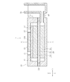
以下、本発明の実施形態について図面を参照しながら説明する。ここで図1及び図2において三次元空間の各方向を符号X、Y、Zで示す。
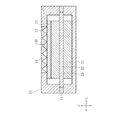
図1は、本発明に係る空気二次電池1のX−Z平面における断面図である。図2は、図1中のA‐A線に沿う断面を示した断面図である。
Hereinafter, embodiments of the present invention will be described with reference to the drawings. Here, in FIG. 1 and FIG. 2, each direction of the three-dimensional space is indicated by reference signs X, Y, and Z.
FIG. 1 is a cross-sectional view in the XZ plane of an air
空気二次電池1は、「筐体」としての電池ケース10、電解液貯蔵部30、連結部40を備える。
The air
電池ケース10は、内部に収容部11が形成され、電池ケース10の外部と収容部11との間に空気を導通する通気口12が形成されている。通気口12は、本実施例では電池ケース10のX方向に離間した位置に2つ形成されている。また電池ケース10は、2つの通気口12を結ぶ位置に蓋体13を備える。
The
電池ケース10は、負極21、セパレータ22、及び空気極23が積層された電極体20と撥水性膜24とを電解液と共に収容部11に収容する。
The
負極21は、詳細を後述するように水素吸蔵合金を含む素材で形成され、収容部11の内底面に配置されている。
The
セパレータ22は、一般的なニッケル水素電池用のセパレータであり、負極21に載置されると共に、四方の端部が電池ケース10の上部と下部とによって挟み込まれて固定される。ここで電池ケース10は、セパレータ22の端部の隙間から外部に電解液が漏出しないようガスケット14で封止されている。
The
空気極23は、詳細を後述するように酸素発生と酸素還元の二元機能を有する触媒を含み、酸素の出入りを妨げないように適度な撥水性を備えると共に、セパレータ22に載置される。
The
撥水性膜24は、空気を透過させるが電解液を透過させない素材で形成され、空気極23に載置されると共に、上面が2つの通気口12及び蓋体13に接するように配置される。蓋体13は、図2に示すようにZ−Y平面における断面が複数の山谷を有する形状であり、その谷の部分が2つの通気口12を連通させるX方向の複数の通気路130を構成すると共に、その山の頂部が撥水性膜24をZ方向上側から押さえつけて固定している。
The water-
2つの通気口12は、いずれか一方から他方へ、通気路130を通じて空気が流れる。通気路130を流れる空気は、その通気路130に面する撥水性膜24の内部に拡散する。そして撥水性膜24は、内部に拡散した空気を直下に接する空気極23に透過させる。それによって撥水性膜24は、ガス拡散層として機能する。また撥水性膜24は、空気極23から発生する酸素を通気路130へ透過させる。通気路130へ透過した酸素は、通気口12を通じて電池ケース10の外部の大気中に放出される。
Air flows through the
ここで電池ケース10は、例えば送風機を設けることによって、2つの通気口12の間に強制的に空気の流れを形成するのが好ましい。それによって空気二次電池1は、撥水性膜24を介して空気極23に安定的に酸素が供給され、高容量や高出力に対応することができる。
Here, it is preferable that the
一方、電池ケース10の内部の電解液は、撥水性膜24によって通気口12及び通気路130への透過が妨げられる。そのため電池ケース10の内部の電解液の圧力が上昇したときに、通気口12を介して電解液が外部へ漏出する虞を低減することができる。
On the other hand, permeation of the electrolyte inside the
電解液貯蔵部30は、内部に電解液を貯蔵すると共に、連結部40を介して電池ケース10に連結されている。そして電解液貯蔵部30の内部と電池ケース10の収容部11とが連結されているため、電解液は、両者の間を移動することができる。このため充電時に空気極23が水を生成することにより電解液が増加した場合には、収容部11の内部の過剰な電解液は、電解液貯蔵部30へ移動して貯蔵される。また放電時に空気極23が水を分解することにより電解液が減少した場合には、電解液貯蔵部30に貯蔵された電解液が収容部11へ移動して空気極23における電解液の不足を補うことができる。
The electrolytic
次に空気極23における三相界面について、より具体的に説明する。
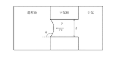
図3は、空気極23の細孔を模式的に表す断面図である。
Next, the three-phase interface in the
FIG. 3 is a cross-sectional view schematically showing the pores of the
より詳しくは図3は、空気極23の細孔を直径dの円形の孔と仮定し、この細孔の一方側に空気が存在すると共に他方側から電解液が浸透する瞬間の三相界面の状態を示す。このとき電解液の特性から決まる表面張力をγ、空気極23と電解液との接触角をΘとすると、細孔に電解液が浸透する瞬間の電解液の浸透圧POは次式で表される。
PO=4γcosΘ/d・・・(3)
式(3)においてcosΘの値は、空気極23の撥水性度合いが高いほど大きくなり浸透圧POを上昇させる。また細孔の直径dが小さいほど浸透圧POが上昇する。このため空気極23の細孔に電解液を適度に浸透させるために必要な圧力は、空気極23の撥水性度合と細孔径分布に依存する。そして空気極23の細孔に電解液が浸透して三相界面が良好に維持されるためには、特に放電時において電解液が減少した場合であっても、電解液の圧力が式(3)で表される浸透圧POよりも高い状態である必要がある。
More specifically, FIG. 3 assumes that the pores of the
P O = 4γ cos Θ / d (3)
The value of cosΘ in equation (3) increases the larger becomes osmotic pressure P O as water-repellent degree of the
ここで空気二次電池1は、図1に示すように、電解液貯蔵部30における液面高さが空気極23の最上面を基準として高さHだけ高く設定されている。電解液貯蔵部30の内部は電池ケース10の収容部11に連通し、また負極21及びセパレータ22は電解液を透過する。そのため空気極23における電解液の静水圧PHは、電解液貯蔵部30の液面高さを高くすることによって次式に従って上昇させることができる。
PH=ρGH・・・(4)
ここでρは電解液の密度、Gは重力加速度を表す。具体的には例えばρ=1.23g/cm3、G=9.8m/s2とした場合、H=10mmの条件下において静水圧PHは約120Paとなる。
Here, in the air
P H = ρGH (4)
Here, ρ represents the density of the electrolytic solution, and G represents the acceleration of gravity. Specifically, for example ρ = 1.23g / cm 3, when the G = 9.8m / s 2, the hydrostatic pressure P H under the conditions of H = 10 mm is about 120 Pa.
このため電解液貯蔵部30における液面高さが空気極23の最上面よりも高い状態であることによって、空気極23において電解液が空気極23の細孔に浸透するために必要な浸透圧POを電解液の静水圧PHが下回る虞を低減することができる。それによって空気二次電池1は、電解液が減少する放電時であっても空気極23の内部の電解液が枯渇せず安定的に放電を行うことができる。
Therefore, the osmotic pressure required for the electrolyte to permeate into the pores of the
一方、充電時において電解液が増加した場合には、空気極23において過剰に生成された電解液が電解液貯蔵部30に移動して貯蔵される。ここで空気極23における電解液の静水圧PHが過剰に上昇した場合には、空気極23による電解液の吸収量が飽和することが起こり得る。しかし撥水性膜24は、空気極23の上面に接すると共に、通気口12及び通気路130を電池ケース10の内側から覆うため、電解液の圧力が上昇した場合であっても電解液が電池ケース10の外部へ漏出する虞を低減することができる。それによって、例えば、充放電を繰り返すことにより空気極23と電池ケース10との隙間や空気極23自体に亀裂が発生した場合であっても、電解液の漏出による減少を防止することができる。
On the other hand, when the electrolyte increases during charging, the electrolyte generated excessively in the
また上述のように空気極23による電解液の吸収量が飽和した場合には、空気極23の内部の細孔が全て電解液で満たされることになり、三相界面の面積が最適値よりも減少してしまう虞が生ずる。そのため電解液貯蔵部30における電解液の液面高さは、そのような状態にならない範囲で、上限値が設定されるのが好ましい。例えば電解液貯蔵部30における電解液の量を徐々に増加し、空気極23の内部の細孔が全て電解液で埋まった時点の液面高さHLを事前に確認しておく。そして充放電に使用する空気二次電池1の製造工程において、電解液を注ぎ入れるときに電解液貯蔵部30における電解液の液面高さHを0からHLの間に設定する。それによって空気二次電池1は、空気極23に対する電解液の過剰な浸透を抑制することができ、三相界面の面積が最適値よりも減少することによって放電電圧が低下する虞を低減することができる。
[実施例]
When the amount of electrolyte absorbed by the
[Example]
1.空気二次電池1の製造
(実施例1)
(1)空気極23の製造
(触媒合成)
空気極23の触媒には、酸素発生と酸素還元に対する二元触媒活性を持つバイクロア型のビスマスイリジウム酸化物を使用した。Bi(NO4)3・5H2OとH2IrCl6・6H2Oとを同じ濃度になるように75℃の蒸留水に溶解し、撹拌・混合してから、2Mol%/LのNaOH水溶液を加えた。このときの浴温度は75℃であり、酸素パブリングを行いながら3日間撹拌した。これによって生じた沈殿物を含む溶液を85℃に維持し蒸発乾燥させてペースト状とした。このペースト状の生成物を蒸発皿に移し、120℃の環境下で12時間乾燥させてから乳鉢で粉砕した後、空気雰囲気下600℃の環境下で2時間焼成した。また焼成物中に含まれる副生成物を除去するため、70℃の蒸留水を用いて吸引濾過し、バイクロア型のビスマスイリジウム酸化物を単離した。さらにこれを120℃の環境下で12時間乾燥させた後、乳鉢を用いて粉砕することにより空気極23の触媒を合成した。
1. Production of air secondary battery 1 (Example 1)
(1) Production of air electrode 23 (catalyst synthesis)
As the catalyst for the
(空気極極板)
このようにして得られたビスマスイリジウム酸化物の粉末、ニッケル粉末(粒径10〜20μm)、及び市販のPTFE粒子を質量比で20:70:10となるように混合して粘土状になったものを板状に成型した。これを常温で30分間乾燥した後、ニッケルメッシュにプレス圧着した。さらに窒素ガス雰囲気下で370℃、13分間焼成した後、所定のサイズに裁断して空気極23を作製した。
(Air electrode plate)
The thus obtained bismuth iridium oxide powder, nickel powder (
(2)負極の製造
(水素吸蔵合金)
Nd、Zr、Mg、Ni、Alを所定の合金組成になるように混合した。これをアルゴンガス雰囲気中で高周波誘導溶解炉にて融解し、鋳型に流し込み、常温まで冷却して合金インゴットを得た。またこの合金インゴットを1000℃、10時間、アルゴンガス雰囲気中で熱処理を行い、組成が(Nd0.99Zr0.01)0.89Mg0.11Ni3.33Al0.17のインゴットを得た。このインゴットを不活性雰囲気中で機械的に粉砕して篩分けし、粒径60μmの水素吸蔵合金の粉末を得た。
(2) Manufacture of negative electrode (hydrogen storage alloy)
Nd, Zr, Mg, Ni, and Al were mixed so as to have a predetermined alloy composition. This was melted in a high-frequency induction melting furnace in an argon gas atmosphere, poured into a mold, and cooled to room temperature to obtain an alloy ingot. The alloy ingot was heat-treated at 1000 ° C. for 10 hours in an argon gas atmosphere to obtain an ingot having a composition of (Nd 0.99 Zr 0.01 ) 0.89 Mg 0.11 Ni 3.33 Al 0.17 . The ingot was mechanically pulverized in an inert atmosphere and sieved to obtain a hydrogen storage alloy powder having a particle size of 60 μm.
(負極極板)
得られた水素吸蔵合金の粉末100質量部に対して、ポリアクリル酸ナトリウム0.2質量部、カルボシメチルセルロース0.04質量部、スチレンブタジエンゴム(SBR)のディスバージョン30質量部、カーボンブラック0.5質量部、及び水22.4質量部を添加して混練し、負極合材のペーストを調整した。この活物質スラリーを発砲ニッケルに充填し、乾燥後ロール圧延して、体積当たりの合金量を高め、所定のサイズに裁断して負極21を作製した。
(Negative electrode plate)
With respect to 100 parts by mass of the obtained hydrogen storage alloy powder, 0.2 parts by mass of sodium polyacrylate, 0.04 parts by mass of carboxymethyl cellulose, 30 parts by mass of styrene butadiene rubber (SBR),
(負極容量の測定)
上記工程で作製した負極21と、負極21に対し十分に容量の大きな焼結式の水酸化ニッケル正極と、ニッケル水素電池用のセパレータ22を組み合わせ、アクリルケースに挿入し、電解液を一定量注液し、負極容量規制のニッケル水素二次電池の単極セルを作製した。この単極セルを5時間休止後、0.5Itで2.8時間充電後、同レートで放電し(終止電圧=0.70V)、これを複数回繰り返して得られた電池容量の最大値を負極21の容量とした。このとき負極21の容量は640mAhであった。
(Measurement of negative electrode capacity)
A
(3)収容部11の構成
上記工程で容量測定を行なった負極21(40mm×40mm、厚さ0.25mm)と、ニッケル水素電池用のセパレータと、上記工程で作製した空気極23(40mm×40mm、厚さ0.2mm)と、PTFEとカーボンにより撥水処理を施したカーボン不織布(45mm×45mm、厚さ0.2mm)をこの順番で重ねて電池ケース10の収容部11に配置し、蓋体13を取り付けることによりZ方向から押さえつけるように固定した。5mol/LのKOH水溶液を電解液として使用し、電解液貯蔵部30に注ぎ入れることにより、電解液貯蔵部30に連通した収容部11に対しても電解液を注いだ。実施例1では、空気極最上面の高さを基準としたときの電解液貯蔵部30における電解液の液面高さHが10mmになるまで電解液を注ぎ、空気二次電池1とした。このとき注いだ電解液の量は、約50mLであった。
(3) Configuration of
(電池特性評価)
上記構成の空気二次電池1を25℃環境下で1時間静置し、電極体20に電解液を吸収させた後、空気極23の触媒量1gに対し100mAとなる電流値で10時間充電した。また同レートで空気二次電池1の放電(終止電圧=0.00V)を行なった。そして充放電中のセル電圧を測定した。尚、通気路130には実施例の充放電を通して、常に、1分間当たり0.8mLの大気を流し続けた。
(Battery characteristics evaluation)
The air
(実施例2)
上記の実施例1における充放電の終了後、実施例1の空気二次電池1を1時間静置し、電解液貯蔵部30における電解液の液面高さHが5mmになるように再設定することにより、実施例2の空気二次電池1とした。そして実施例2の空気二次電池1に対して、実施例1と同様に1サイクルの充放電を行うことにより電池特性を評価した。
(Example 2)
After the completion of charging / discharging in Example 1 above, the air
(実施例3)
上記の実施例2における充放電の終了後、実施例2の空気二次電池1を1時間静置し、電解液貯蔵部30における電解液の液面高さHが0mmになるように再設定することにより、実施例3の空気二次電池1とした。そして実施例3の空気二次電池1に対して、実施例1と同様に1サイクルの充放電を行うことにより電池特性を評価した。
(Example 3)
After the end of charging / discharging in Example 2, the air
(比較例1)
上記の実施例3における充放電の終了後、実施例3の空気二次電池1を1時間静置し、電解液貯蔵部30における電解液の液面高さHが−10mmになるように再設定することにより、比較例1の空気二次電池1とした。そして比較例1の空気二次電池1に対して、実施例1と同様に1サイクルの充放電を行うことにより電池特性を評価した。尚、比較例1では電解液貯蔵部30における電解液の液面の高さが収容部11の底面よりも低くなるものの、少なくともセパレータ22及び負極21が電解液を保持しているため、充放電自体は可能である。
(Comparative Example 1)
After the completion of charging / discharging in Example 3 above, the air
2.空気二次電池1の評価結果
(1)充電特性
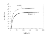
図4は、実施例1〜3及び比較例1における充電特性を示すグラフである。図4において横軸は空気二次電池1を充電することにより増加する充電容量を示し、縦軸はそのときのセル電圧を示す。ある充電容量まで空気二次電池1を充電するときに、よりセル電圧が上昇する二次電池ほど、内部における反応抵抗が高く、充電時に高い電圧を印加する必要がある。図4より、実施例1〜3では充電特性がほとんど変わらず、比較例1ではセル電圧が上昇している。より具体的には、空気二次電池1を10時間充電した時点の電圧を充電電圧とすると、実施例2の充電電圧は実施例1の充電電圧よりも0.9mV高く、実施例3の充電電圧は実施例1の充電電圧よりも2.0mV高かった。比較例1の充電電圧に関しては、実施例1の充電電圧よりも17.3mV高かった。
2. Evaluation Results of Air Secondary Battery 1 (1) Charging Characteristics FIG. 4 is a graph showing charging characteristics in Examples 1 to 3 and Comparative Example 1. In FIG. 4, the horizontal axis indicates the charge capacity that is increased by charging the air
(2)放電特性
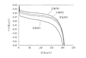
図5は、実施例1〜3及び比較例1における放電特性を示すグラフである。図5において横軸は空気二次電池1を放電することにより減少する充電容量を示し、縦軸はそのときのセル電圧を示す。ある放電容量まで空気二次電池1を放電するときに、よりセル電圧が下降する二次電池ほど、内部における反応抵抗が高く、放電時に高い電圧を出力することができなくなってしまう。図5より、放電特性は実施例1が最も良好で、実施例2、実施例3、比較例1の順で低下していく。より具体的には、空気二次電池1の充電容量の50%まで放電したときの電圧を放電電圧とすると、実施例2の放電電圧は実施例1の放電電圧よりも4.4mV低く、実施例3の放電電圧は実施例1の充電電圧よりも7.1mV低かった。比較例1の放電電圧に関しては、実施例1の放電電圧よりも17.8mV低かった。
(2) Discharge characteristics FIG. 5 is a graph showing the discharge characteristics in Examples 1 to 3 and Comparative Example 1. In FIG. 5, the horizontal axis indicates the charge capacity that decreases by discharging the air
3.特性評価の考察
上記の評価結果から、電解液貯蔵部30における電解液の液面高さHを高くすることにより、充電時における反応抵抗を抑制して充電特性を向上させることができた。これは電極体20に電解液が速やかに供給されることで、電解液が枯渇しなかったためと考えられる。また電解液貯蔵部30における電解液の液面高さHを高くすることにより、放電時における反応抵抗を抑制して放電特性を向上させることができた。これは電解液が減少する放電時であっても、電解液の静水圧の低下が抑制され、撥水性を有する空気極23の内部の細孔に電解液が浸透したことにより、放電に有利な三相界面が多く形成されたことに起因すると考えられる。
3. Consideration of characteristic evaluation From the above evaluation results, by increasing the liquid level height H of the electrolytic solution in the electrolytic
以上で実施形態の説明を終えるが、本発明は上記の実施形態に限定されるものではない。例えば上記の空気二次電池1は、水素空気二次電池を例として説明したが、アルカリ電解液を使用するその他の空気二次電池においても空気極23における電池反応は同様であり、適用が可能である。また上記の空気二次電池1は、電解液の静水圧によって空気極23における細孔へ浸透させたが、ポンプ等を用いて電解液の圧力を調整しても同様の作用効果が得られる。
Although the description of the embodiment has been completed above, the present invention is not limited to the above-described embodiment. For example, the air
1 空気二次電池
10 電池ケース
11 収容部
12 通気口
13 蓋体
14 ガスケット
20 電極体
21 負極
22 セパレータ
23 空気極
24 撥水性膜
30 電解液貯蔵部
40 連結部
130 通気路
DESCRIPTION OF
Claims (4)
前記電極体をアルカリ電解液と共に収容する筐体と、
前記筐体と連通しており、充電時に増加する前記アルカリ電解液を貯蔵し、放電時に減少する前記アルカリ電解液を供給する電解液貯蔵部と、を備え、
前記電解液貯蔵部の前記アルカリ電解液の液面高さが前記空気極の最上面よりも高い、空気二次電池。 An electrode body in which an air electrode and a negative electrode are laminated via a separator;
A housing that houses the electrode body together with an alkaline electrolyte;
An electrolyte storage unit that communicates with the housing, stores the alkaline electrolyte that increases during charging, and supplies the alkaline electrolyte that decreases during discharge; and
The air secondary battery, wherein the alkaline electrolyte has a liquid level height higher than that of the uppermost surface of the air electrode.
前記筐体は、内外に空気を導通する通気口が形成され、
前記撥水性膜は、一面側が前記空気極に接し、他面側が前記通気口を前記筐体内部から覆うように配置される、空気二次電池。 The air secondary battery according to claim 1, further comprising a water-repellent film that allows air to pass therethrough and does not pass the alkaline electrolyte.
The casing is formed with a vent hole that conducts air inside and outside,
The water repellent film is an air secondary battery in which one surface side is in contact with the air electrode and the other surface side is disposed so as to cover the vent from the inside of the housing.
Priority Applications (1)
| Application Number | Priority Date | Filing Date | Title |
|---|---|---|---|
| JP2016066380A JP6761655B2 (en) | 2016-03-29 | 2016-03-29 | Air secondary battery |
Applications Claiming Priority (1)
| Application Number | Priority Date | Filing Date | Title |
|---|---|---|---|
| JP2016066380A JP6761655B2 (en) | 2016-03-29 | 2016-03-29 | Air secondary battery |
Publications (2)
| Publication Number | Publication Date |
|---|---|
| JP2017183003A true JP2017183003A (en) | 2017-10-05 |
| JP6761655B2 JP6761655B2 (en) | 2020-09-30 |
Family
ID=60006215
Family Applications (1)
| Application Number | Title | Priority Date | Filing Date |
|---|---|---|---|
| JP2016066380A Active JP6761655B2 (en) | 2016-03-29 | 2016-03-29 | Air secondary battery |
Country Status (1)
| Country | Link |
|---|---|
| JP (1) | JP6761655B2 (en) |
Cited By (1)
| Publication number | Priority date | Publication date | Assignee | Title |
|---|---|---|---|---|
| JP2017217543A (en) * | 2017-09-22 | 2017-12-14 | 株式会社大一商会 | Game machine |
Citations (5)
| Publication number | Priority date | Publication date | Assignee | Title |
|---|---|---|---|---|
| JPS5351448A (en) * | 1976-10-21 | 1978-05-10 | Kogyo Gijutsuin | Method of operating metal air battery |
| JP2009032399A (en) * | 2007-07-24 | 2009-02-12 | Toyota Motor Corp | Air battery system |
| JP2010244731A (en) * | 2009-04-01 | 2010-10-28 | Toyota Motor Corp | Air battery |
| JP2012064477A (en) * | 2010-09-16 | 2012-03-29 | Doshisha | Hydrogen/air secondary battery |
| JP2015032450A (en) * | 2013-08-02 | 2015-02-16 | 日産自動車株式会社 | Air battery system |
-
2016
- 2016-03-29 JP JP2016066380A patent/JP6761655B2/en active Active
Patent Citations (5)
| Publication number | Priority date | Publication date | Assignee | Title |
|---|---|---|---|---|
| JPS5351448A (en) * | 1976-10-21 | 1978-05-10 | Kogyo Gijutsuin | Method of operating metal air battery |
| JP2009032399A (en) * | 2007-07-24 | 2009-02-12 | Toyota Motor Corp | Air battery system |
| JP2010244731A (en) * | 2009-04-01 | 2010-10-28 | Toyota Motor Corp | Air battery |
| JP2012064477A (en) * | 2010-09-16 | 2012-03-29 | Doshisha | Hydrogen/air secondary battery |
| JP2015032450A (en) * | 2013-08-02 | 2015-02-16 | 日産自動車株式会社 | Air battery system |
Cited By (1)
| Publication number | Priority date | Publication date | Assignee | Title |
|---|---|---|---|---|
| JP2017217543A (en) * | 2017-09-22 | 2017-12-14 | 株式会社大一商会 | Game machine |
Also Published As
| Publication number | Publication date |
|---|---|
| JP6761655B2 (en) | 2020-09-30 |
Similar Documents
| Publication | Publication Date | Title |
|---|---|---|
| Chakkaravarthy et al. | Zinc—air alkaline batteries—A review | |
| ES2406964T3 (en) | New positive silver electrode for alkaline batteries | |
| JP5626872B2 (en) | Hydrogen / air secondary battery | |
| ES2696399T3 (en) | Battery with removable air electrode | |
| EP2824745A1 (en) | Rechargeable zinc-air flow battery | |
| EA013282B1 (en) | BIFUNCTIONAL AIR ELECTRODE | |
| JPWO2010100752A1 (en) | Air electrode and non-aqueous air battery | |
| CN106935802B (en) | A metal-oxygen secondary battery | |
| JP6811086B2 (en) | Air secondary battery | |
| US11355751B2 (en) | Air electrode for air secondary battery and air secondary battery | |
| US8304121B2 (en) | Primary aluminum hydride battery | |
| JP2020087554A (en) | Electrolyte solution for zinc battery and zinc battery | |
| JP2017228351A (en) | Reversible fuel cell storage battery | |
| CA3135616A1 (en) | Ph-universal aqueous rechargeable hydrogen batteries | |
| JP6836603B2 (en) | Metal-air battery | |
| JP6263371B2 (en) | Metal air battery | |
| JP6761655B2 (en) | Air secondary battery | |
| KR101713401B1 (en) | Zinc-air secondary battery and preparation method thereof | |
| JPH0447676A (en) | Manufacturing method for sealed storage batteries | |
| US10211464B2 (en) | Electrochemical cell aluminum-manganese | |
| JP2004506300A (en) | Battery cathode | |
| JP2021136165A (en) | Air electrode for air secondary battery and air secondary battery | |
| JP2017076538A (en) | Method for manufacturing air electrode of air secondary battery, and air-hydrogen secondary battery | |
| JP2021082383A (en) | Negative electrode for zinc battery | |
| JP2020187862A (en) | A hydrogen storage alloy negative electrode for a hydrogen air secondary battery and a hydrogen air secondary battery containing this hydrogen storage alloy negative electrode. |
Legal Events
| Date | Code | Title | Description |
|---|---|---|---|
| RD04 | Notification of resignation of power of attorney |
Free format text: JAPANESE INTERMEDIATE CODE: A7424 Effective date: 20170511 |
|
| A621 | Written request for application examination |
Free format text: JAPANESE INTERMEDIATE CODE: A621 Effective date: 20190124 |
|
| A977 | Report on retrieval |
Free format text: JAPANESE INTERMEDIATE CODE: A971007 Effective date: 20191223 |
|
| A131 | Notification of reasons for refusal |
Free format text: JAPANESE INTERMEDIATE CODE: A131 Effective date: 20200122 |
|
| A521 | Request for written amendment filed |
Free format text: JAPANESE INTERMEDIATE CODE: A523 Effective date: 20200316 |
|
| A02 | Decision of refusal |
Free format text: JAPANESE INTERMEDIATE CODE: A02 Effective date: 20200520 |
|
| RD13 | Notification of appointment of power of sub attorney |
Free format text: JAPANESE INTERMEDIATE CODE: A7433 Effective date: 20200625 |
|
| A521 | Request for written amendment filed |
Free format text: JAPANESE INTERMEDIATE CODE: A821 Effective date: 20200626 |
|
| A521 | Request for written amendment filed |
Free format text: JAPANESE INTERMEDIATE CODE: A523 Effective date: 20200807 |
|
| A911 | Transfer to examiner for re-examination before appeal (zenchi) |
Free format text: JAPANESE INTERMEDIATE CODE: A911 Effective date: 20200818 |
|
| TRDD | Decision of grant or rejection written | ||
| A01 | Written decision to grant a patent or to grant a registration (utility model) |
Free format text: JAPANESE INTERMEDIATE CODE: A01 Effective date: 20200902 |
|
| A61 | First payment of annual fees (during grant procedure) |
Free format text: JAPANESE INTERMEDIATE CODE: A61 Effective date: 20200907 |
|
| R150 | Certificate of patent or registration of utility model |
Ref document number: 6761655 Country of ref document: JP Free format text: JAPANESE INTERMEDIATE CODE: R150 |
|
| R250 | Receipt of annual fees |
Free format text: JAPANESE INTERMEDIATE CODE: R250 |
|
| R250 | Receipt of annual fees |
Free format text: JAPANESE INTERMEDIATE CODE: R250 |
|
| R250 | Receipt of annual fees |
Free format text: JAPANESE INTERMEDIATE CODE: R250 |