JP2017183473A - Cover for preventing leakage of leaked fluid - Google Patents
Cover for preventing leakage of leaked fluid Download PDFInfo
- Publication number
- JP2017183473A JP2017183473A JP2016067776A JP2016067776A JP2017183473A JP 2017183473 A JP2017183473 A JP 2017183473A JP 2016067776 A JP2016067776 A JP 2016067776A JP 2016067776 A JP2016067776 A JP 2016067776A JP 2017183473 A JP2017183473 A JP 2017183473A
- Authority
- JP
- Japan
- Prior art keywords
- belt
- fluid
- cover
- cover member
- prevention cover
- Prior art date
- Legal status (The legal status is an assumption and is not a legal conclusion. Google has not performed a legal analysis and makes no representation as to the accuracy of the status listed.)
- Granted
Links
Images
Landscapes
- Housings And Mounting Of Transformers (AREA)
Abstract
【課題】汎用性のある漏洩流体の流出防止カバーを提供する。【解決手段】流出防止カバー10は、一組のベルト部材1・1と箱状のカバー部材2を備える。ベルト部材1は、管Pの外周に装着できる。カバー部材2は、一方の面を開口し、対向する一対の側面及び底面を山折りと谷折りが繰り返す屈曲自在なアコーディオン構造で構成している。ベルト部材1は、案内部材1gを有する。案内部材1gは、先端金具1aからバックル1bに亘り、ベルト部材1の長手方向に沿って、配置されている。カバー部材2は、複数のリング部材3rをカバー部材2の開口端20eに有する。これらのリング部材3rは、一対の案内部材1g・1gが対向配置された状態で、案内部材1g・1gに案内される。カバー部材2の開口端20eを管Pの外周に密着することで、管Pから漏洩した流体Lをカバー部材2の内部に回収できる。【選択図】図1PROBLEM TO BE SOLVED: To provide a versatile outflow prevention cover for a leaking fluid. An outflow prevention cover 10 includes a set of belt members 1.1 and a box-shaped cover member 2. The belt member 1 can be attached to the outer periphery of the pipe P. The cover member 2 has a flexible accordion structure in which one surface is opened and a pair of opposite side surfaces and bottom surfaces are repeatedly folded in a mountain fold and a valley fold. The belt member 1 has a guide member 1 g. The guide member 1g is arranged from the tip metal fitting 1a to the buckle 1b along the longitudinal direction of the belt member 1. The cover member 2 has a plurality of ring members 3r at the open end 20e of the cover member 2. These ring members 3r are guided by the guide members 1g and 1g in a state where the pair of guide members 1g and 1g are arranged so as to face each other. By bringing the open end 20e of the cover member 2 into close contact with the outer periphery of the pipe P, the fluid L leaked from the pipe P can be recovered inside the cover member 2. [Selection diagram] Fig. 1
Description
本発明は、流体の漏洩防止カバーに関する。特に、発電所又は変電所などに設置した管から漏洩した油などの流体が地面などの外部に流出することを防止する、漏洩流体の流出防止カバーの構造に関する。 The present invention relates to a fluid leakage prevention cover. In particular, the present invention relates to a leaked fluid outflow prevention cover structure for preventing fluid such as oil leaked from a pipe installed in a power plant or substation from flowing out of the ground or the like.
例えば、発電所又は変電所などでは、ラジエータ付きの変圧器を設置している。そして、変圧器本体とラジエータを送油管で接続し、変圧器本体とラジエータの間に、ラジエータで冷却した油を循環させることで、変圧器本体を冷却している。 For example, in a power plant or a substation, a transformer with a radiator is installed. And a transformer main body and a radiator are connected with an oil feed pipe, and the transformer main body is cooled by circulating the oil cooled with a radiator between the transformer main body and a radiator.
このような、ラジエータ付きの変圧器は、変圧器本体とラジエータを容易に分離又は連結するために、変圧器本体側から延びる第1の送油管の端部に設けた第1のフランジと、ラジエータ側から延びる第2の送油管の端部に設けた第2のフランジと、を備え、パッキンを介して、第1のフランジと第2のフランジをボルト部材で連結している。 Such a transformer with a radiator includes a first flange provided at an end of a first oil feeding pipe extending from the transformer main body side, and a radiator for easily separating or connecting the transformer main body and the radiator. And a second flange provided at the end of the second oil feeding pipe extending from the side, and the first flange and the second flange are connected by a bolt member via a packing.
ところで、経年変化などでパッキンが劣化してくると、第1のフランジと第2のフランジの間から油が漏洩し、油が地面に流出する心配があった。このような事態になると、油が地中に浸透して、土壌又は水質を汚染する遠因になる心配があった。 By the way, when the packing deteriorates due to secular change or the like, there is a concern that oil leaks from between the first flange and the second flange, and the oil flows out to the ground. In such a situation, there is a concern that the oil penetrates into the ground and becomes a remote cause of contaminating soil or water quality.
上述したような事態を防止するため、互いに連結した一組のフランジの周囲を密封自在に覆う一対の半円筒状の透明カバーと、一対の透明カバーの内部に収容自在な油用吸着材で構成した漏油防止カバーが開示されている(例えば、特許文献1参照)。 In order to prevent the above-described situation, a pair of semi-cylindrical transparent covers that covers the periphery of a pair of flanges connected to each other in a sealable manner and an adsorbent for oil that can be accommodated inside the pair of transparent covers An oil leakage prevention cover is disclosed (see, for example, Patent Document 1).
特許文献1による漏油防止カバーは、一対の透明カバーの一端部を回動自在に連結し、一対の透明カバーの他端部側を開閉自在に構成し、一方の透明カバーの他端部にロック操作レバーを取り付け、他方の透明カバーの他端部に掛け金錠を取り付けることで、一対の透明カバーを開いて、一組のフランジに素早く導入できる、としている。
The oil leakage prevention cover according to
特許文献1に開示した漏油防止カバーに類似したものとして、絶縁油を内部に収容した柱上変圧器の外周が落雷などで破損し、絶縁油が漏洩した場合に、漏洩部を被って、絶縁油の外部への流出を防止できる、流体漏れ防止カバーが開示されている(例えば、特許文献2参照)。
As similar to the oil leakage prevention cover disclosed in
特許文献2による流体漏れ防止カバーは、有底筒形の透明カバーと、透明カバーの開口端の周縁部に装着し、柱上変圧器の外周に密着自在なリング状のパッキンと、パッキンの内壁に嵌合した円板状の油吸着マットと、一端部を透明カバーの中間部に係留し、柱上変圧器の外周に延在して密着するように、他端部を互いに係留自在な一組のゴム紐と、を備えている。
The fluid leakage prevention cover according to
特許文献2による流体漏れ防止カバーは、油吸着マットを柱上変圧器の漏洩部に当接し、一組のゴム紐の他端部を互いに係留し、漏洩部を油吸着マットで押圧し、油吸着マットを介して、漏洩した絶縁油を透明カバーの内部に収容することで、絶縁油が外部に流出することを防止できる、としている。
In the fluid leakage prevention cover according to
発電所又は変電所などに設置した管から漏油が発見又は検出された場合には、漏油が地面などの外部に流出することを直ちに防止する必要がある。この場合、漏油個所の部品を交換して漏油を防止する、いわゆる、完全復旧を即座に実施すことは困難なことが多い。完全復旧を後日に予定し、漏油が地面などの外部に流出すること早急に防止する、いわゆる、応急対策を直ちに実施する必要がある。 When oil leakage is detected or detected from a pipe installed in a power plant or substation, it is necessary to immediately prevent the oil leakage from flowing out of the ground or the like. In this case, it is often difficult to immediately perform a so-called complete recovery in which oil leakage is prevented by replacing parts at the oil leakage location. It is necessary to implement a so-called first-aid measure to prevent the oil leak from spilling out to the outside such as the ground.
漏油個所をウエス(布切れ)などで塞ぐ、又は、漏油を回収する受け皿を設置するなどの応急対策も有効である。しかし、特許文献1による漏油防止カバー、又は、特許文献2による流体漏れ防止カバーを用意しておけば、漏油の外部への流出を早急にかつ確実に防止できる、と考えられる。
It is also effective to take emergency measures, such as closing the oil spill area with a waste cloth or installing a tray to collect the oil spill. However, if the oil leakage prevention cover according to
しかし、特許文献1による漏油防止カバーは、一対の透明カバーの内径が送油管の回りに密着するように構成しているので、異なる外径の送油管が混在している現状では、複数種類の漏油防止カバーを用意する必要がある。
However, the oil leakage prevention cover according to
発電所又は変電所などでは、多数の送油管を配置している。又、これらの送油管の中から漏油を予測することは、一般に困難であり、複数種類の漏油防止カバーを用意しておくことは、経済的な負担が大きいという問題がある。異なる外径の送油管に対応できるように、汎用性のある漏洩流体の流出防止カバーが求められている。 A large number of oil pipes are arranged in a power plant or substation. In addition, it is generally difficult to predict oil leakage from these oil feeding pipes, and preparing a plurality of types of oil leakage prevention covers has a problem of high economic burden. There is a need for a versatile leakage prevention cover that can accommodate oil pipes with different outer diameters.
一方、特許文献2による流体漏れ防止カバーは、伸縮自在な一組のゴム紐で管体の回りを閉じているので、異なる外径の送油管に対応できる。しかし、特許文献2による流体漏れ防止カバーは、送油管の外径方向に沿って亀裂が生じた場合には、円板状の油吸着マットでは、漏油を阻止すること困難と考えられる。送油管の曲面に油吸着マットの平面が当接しているからである。送油管の外径方向の亀裂に対応できる、汎用性のある漏洩流体の流出防止カバーが求められている。そして、以上のことが本発明の課題といってよい。
On the other hand, since the fluid leakage prevention cover according to
本発明は、このような課題に鑑みてなされたものであり、管から漏洩した流体が外部に流出することを防止する漏洩流体の流出防止カバーであって、異なる外径の管に対応できるように、汎用性のある漏洩流体の流出防止カバーを提供することを目的とする。 The present invention has been made in view of such a problem, and is a leaked fluid outflow prevention cover for preventing fluid leaking from a tube from flowing out to the outside, so that it can cope with tubes of different outer diameters. Another object of the present invention is to provide a versatile leakage prevention cover for leakage fluid.
本発明者らは、非圧縮性の流体を内部に有する管の外周に装着自在な一組の帯状のベルト部材と、対向する一対の側面及び底面を山折りと谷折りが繰り返す屈曲自在なアコーディオン構造で構成した箱状のカバー部材で漏洩流体の流出防止カバーを構成し、ベルト部材には、その長手方向に沿って案内部材を配置し、カバー部材には、一対の案内部材に案内される複数のリング部材を開口端に配置し、カバー部材の開口端を管の外周に密着させることで、異なる外径の管に対応できるように、漏洩流体をカバー部材の内部に回収できることを見出し、これに基づいて、以下のような新たな漏洩流体の流出防止カバーを発明するに至った。 The inventors have a set of belt-shaped belt members that can be attached to the outer periphery of a tube having an incompressible fluid therein, and a bendable accordion that repeats a mountain fold and a valley fold on a pair of opposing side and bottom surfaces. A box-shaped cover member having a structure constitutes a leakage prevention cover for leakage fluid, a guide member is disposed along the longitudinal direction of the belt member, and the cover member is guided by a pair of guide members. A plurality of ring members are arranged at the open end, and the open end of the cover member is brought into close contact with the outer periphery of the pipe, thereby finding that the leaked fluid can be collected inside the cover member so that it can be used for pipes having different outer diameters. Based on this, the inventors have invented the following new leakage prevention cover for leakage fluid.
(1)本発明による漏洩流体の流出防止カバーは、管の内部から漏洩した非圧縮性の流体が外部に流出することを防止できる漏洩流体の流出防止カバーであって、先端金具を一端部に有し、一端部側を係止自在なバックルを他端部に有し、前記管の外周に装着自在な一組の帯状のベルト部材と、一方の面を開口し、対向する一対の側面及び底面を山折りと谷折りが繰り返す屈曲自在なアコーディオン構造で構成した箱状のカバー部材と、を備え、前記ベルト部材は、前記先端金具から前記バックルに亘り、当該ベルト部材の長手方向に沿って、幅方向の一方の端部に配置された案内部材を有し、前記カバー部材は、一対の前記案内部材が対向配置された状態で、前記案内部材に案内される複数のリング部材を一対の前記側面の開口端に有し、前記カバー部材は、前記流体を内部に回収自在に、前記開口端を前記管の外周に密着できる。 (1) A leaked fluid outflow prevention cover according to the present invention is a leaky fluid outflow prevention cover capable of preventing an incompressible fluid leaking from the inside of a pipe from flowing out to the outside, with a tip fitting at one end. A pair of belt-shaped belt members that have a buckle that can be locked at one end and can be attached to the outer periphery of the tube, a pair of side surfaces that are open on one side, and A box-shaped cover member configured with a flexible accordion structure in which a bottom fold and a valley fold are repeated, and the belt member extends from the tip fitting to the buckle along the longitudinal direction of the belt member. The guide member is disposed at one end in the width direction, and the cover member includes a pair of ring members guided by the guide member in a state where the pair of guide members are opposed to each other. At the open end of the side, Serial cover member freely recovering the fluid therein, it can be in close contact with the opening end on the outer periphery of the tube.
(2)複数の前記リング部材は、少なくとも、前記カバー部材の開口端の四隅に配置されていることが好ましい。 (2) It is preferable that the plurality of ring members are arranged at least at the four corners of the opening end of the cover member.
(3)前記ベルト部材は、その長手方向に沿って配列した複数の係止孔と、前記バックルに配置され、前記係止孔に施錠自在なピン状の留め金と、を有していることが好ましい。 (3) The belt member has a plurality of locking holes arranged along the longitudinal direction thereof, and a pin-shaped clasp that is disposed in the buckle and can be locked to the locking hole. Is preferred.
(4)前記案内部材は、屈曲自在な線状体からなってもよい。 (4) The guide member may be a linear body that can be bent.
(5)前記案内部材は、前記ベルト部材の一方の面に配置された帯状の補助ベルトからなってもよい。 (5) The guide member may include a belt-like auxiliary belt disposed on one surface of the belt member.
(7)前記リング部材は、前記案内部材の外周方向から係脱自在なキーリングからなることが好ましい。 (7) It is preferable that the ring member is formed of a key ring that can be freely engaged and disengaged from an outer peripheral direction of the guide member.
(8)前記カバー部材は、前記流体が流出しないように、少なくとも内面を防水処理していることが好ましい。 (8) It is preferable that at least the inner surface of the cover member is waterproofed so that the fluid does not flow out.
本発明による漏洩流体の流出防止カバーは、管の外周に装着自在な一組の帯状のベルト部材と、対向する一対の側面及び底面をアコーディオン構造で構成した箱状のカバー部材を備え、ベルト部材の長手方向に沿って配置された案内部材とカバー部材の開口端を複数のリング部材で連結しているので、異なる外径の管に対応して、漏洩流体をカバー部材の内部に回収できる。 A leaked fluid outflow prevention cover according to the present invention comprises a pair of belt-shaped belt members that can be mounted on the outer periphery of a pipe, and a box-shaped cover member having an accordion structure on a pair of opposing side surfaces and bottom surface. Since the opening ends of the guide member and the cover member arranged along the longitudinal direction of the cover member are connected by the plurality of ring members, the leaked fluid can be collected in the cover member corresponding to the pipes having different outer diameters.
以下、図面を参照して本発明を実施するための形態を説明する。
[漏洩流体の流出防止カバーの構成]
最初に、本発明の一実施形態による漏洩流体の流出防止カバーの構成を説明する。
Hereinafter, embodiments for carrying out the present invention will be described with reference to the drawings.
[Structure of leak prevention cover for leaked fluid]
First, the configuration of the leakage prevention cover for leakage fluid according to an embodiment of the present invention will be described.
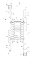
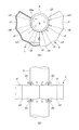
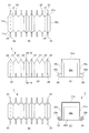
図1は、本発明の一実施形態による漏洩流体の流出防止カバーの構成を示す平面図である。図2は、前記実施形態による漏洩流体の流出防止カバーの一使用例を示す図であり、図2(A)は、カバー部材の開口端を菅の外周に密着した状態を示す正面図、図2(B)は、図2(A)の下面図である。 FIG. 1 is a plan view showing the configuration of a leakage fluid outflow prevention cover according to an embodiment of the present invention. FIG. 2 is a view showing an example of use of the leakage prevention cover for leaked fluid according to the embodiment, and FIG. 2 (A) is a front view showing a state in which the open end of the cover member is in close contact with the outer periphery of the bag. 2 (B) is a bottom view of FIG. 2 (A).
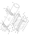
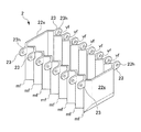
図3は、前記実施形態による漏洩流体の流出防止カバーの他の使用例を示す斜視図である。図4は、前記実施形態による漏洩流体の流出防止カバーに備わるカバー部材の構成を示す斜視図である。 FIG. 3 is a perspective view showing another usage example of the leakage prevention cover according to the embodiment. FIG. 4 is a perspective view illustrating a configuration of a cover member provided in the leakage prevention cover according to the embodiment.
図5は、前記実施形態による漏洩流体の流出防止カバーに備わるカバー部材の構成を示す図であり、図5(A)は、カバー部材の平面図、図5(B)は、カバー部材の正面図、図5(C)は、カバー部材の右側面図、図5(D)は、カバー部材の下面図、図5(E)は、図5(A)のA−A矢視断面図である。 FIGS. 5A and 5B are diagrams showing a configuration of a cover member provided in the leaked fluid outflow prevention cover according to the embodiment, FIG. 5A is a plan view of the cover member, and FIG. 5B is a front view of the cover member. FIG. 5 (C) is a right side view of the cover member, FIG. 5 (D) is a bottom view of the cover member, and FIG. 5 (E) is a cross-sectional view taken along line AA in FIG. 5 (A). is there.
(全体構成)
図1から図5を参照すると、本発明の一実施形態による漏洩流体の流出防止カバー(以下、流出防止カバーと略称する)10は、管Pの内部から漏洩した非圧縮性の流体Lが外部に流出することを防止できる。そして、流出防止カバー10は、一組の帯状のベルト部材1・1と箱状のカバー部材2を備えている。
(overall structure)
Referring to FIGS. 1 to 5, a leaked fluid outflow prevention cover (hereinafter abbreviated as an outflow prevention cover) 10 according to an embodiment of the present invention has an incompressible fluid L leaked from the inside of a pipe P. Can be prevented from leaking. The
図1又は図3を参照すると、ベルト部材1は、先端金具1aを一端部に有している。又、ベルト部材1は、バックル1bを他端部に有している。バックル1bは、ベルト部材1の一端部側を任意の位置で係止できる。そして、ベルト部材1は、管Pの外周に装着できる(図3参照)。
Referring to FIG. 1 or FIG. 3, the
図1から図5を参照すると、カバー部材2は、一方の面を開口している。又、カバー部材2は、対向する一対の側面21s・21s及び底面21bを山折りmfと谷折りvfが繰り返す屈曲自在なアコーディオン構造で構成している(図5参照)。
Referring to FIGS. 1 to 5, the
図1又は図3を参照すると、ベルト部材1は、屈曲自在な線状体からなる案内部材1gを有している。案内部材1gは、先端金具1aからバックル1bに亘り、ベルト部材1の長手方向に沿って、幅方向の一方の端部に配置されている。
Referring to FIG. 1 or FIG. 3, the
図1又は図3及び図5を参照すると、カバー部材2は、複数のリング部材3rを一対の側面21s・21sの開口端20eに有している。これらのリング部材3rは、一対の案内部材1g・1gが対向配置された状態で(図1又は図3参照)、これらの案内部材1g・1gに案内される。
Referring to FIG. 1 or FIG. 3 and FIG. 5, the
図2に示した一使用例では、カバー部材2は、開口端20eを管Pの外周に密着できる。そして、カバー部材2は、管Pから漏洩した流体Lを内部に回収できる。図3に示した他の使用例では、カバー部材2を管Pの下方に配置して、管Pの亀裂Crから漏洩した流体Lを内部に回収できる。
In the example of use shown in FIG. 2, the
図1から図5を参照すると、実施形態による流出防止カバー10は、管Pの外周に装着自在な一組の帯状のベルト部材1・1と、対向する一対の側面21s・21s及び底面21bをアコーディオン構造で構成した箱状のカバー部材2を備え、ベルト部材1の長手方向に沿って配置された案内部材1gとカバー部材2の開口端20eを複数のリング部材3rで連結しているので、異なる外径の管Pに対応して、漏洩流体をカバー部材2の内部に回収できる。
Referring to FIGS. 1 to 5, the outflow prevention cover 10 according to the embodiment includes a pair of belt-
(ベルト部材の構成)
次に、実施形態によるベルト部材1の構成を説明する。図1又は図3を参照すると、ベルト部材1は、合成繊維を密に編み込んだ帯状の布製ベルトで構成することができる。又、ベルト部材1は、天然皮革又は合成皮革で構成した革製ベルトも使用できる。
(Configuration of belt member)
Next, the configuration of the
図1又は図3を参照すると、ベルト部材1は、複数の係止孔1hとピン状の留め金1cを有している。複数の係止孔1hは、ベルト部材1の長手方向に沿って配列されている。留め金1cは、バックル1bに配置されている。留め金1cは、その基端部をバックル1bと回動自在に連結している。留め金1cを起立させた状態で、任意の位置の係止孔1hに留め金1cを挿通でき、この係止孔1hに施錠できる。
Referring to FIG. 1 or FIG. 3, the
図3を参照すると、ベルト部材1は、管Pの外径に対応して、その巻き付け長さを調整できる。又、ベルト部材1は、管Pへの締め付け力も調整できる。図1を参照して、ベルト部材1には、ベルト通し1dを更に配置することが好ましく、ベルト部材1の一端部側をベルト通し1dに挿通することで、ベルト部材1の一端部側を保持できる。
Referring to FIG. 3, the
図1又は図3を参照すると、実施形態による案内部材1gは、鋼線などの線条体で構成しているが、案内部材1gは、ベルト部材1の一方の面に配置された帯状の補助ベルト(図示せず)で構成することもできる。
Referring to FIG. 1 or FIG. 3, the
(カバー部材の構成)
次に、実施形態によるカバー部材2の構成を説明する。図1から図5を参照して、カバー部材2は、シリコーンゴムなどで成形することが好ましい。カバー部材2は、流体Lが流出しないように、少なくとも内面を防水処理しておくことが好ましい。カバー部材2は、図2に示すように、管Pの外周を輪帯状に囲うこともでき、図3に示すように、一方の面を開口した箱形の形状を維持することもできる。
(Configuration of cover member)
Next, the configuration of the
図1から図5を参照すると、カバー部材2は、相反する向きに向かう一対のイヤー(耳片)23・23を備えている。一対のイヤー23・23は、一対の側面21s・21sの開口端20eに連設している。
Referring to FIGS. 1 to 5, the
図1から図5を参照すると、イヤー23には、リング部材3rが挿通自在な穴23hを中央部に開口している。リング部材3rは、穴23hに係脱自在なキーリングからなることが好ましい。リング部材3rをキーリングで構成することで、案内部材1gの外周方向からリング部材3rを係脱できる(図1又は図5参照)。
Referring to FIGS. 1 to 5, the
図1又は図3を参照すると、複数のリング部材3rは、少なくとも、カバー部材2の開口端20eの四隅に配置されている。図3を参照して、これらのリング部材3rを一対の案内部材1g・1gに連結することで、管Pから漏洩した流体Lを回収する受け皿として、カバー部材2を使用できる。流体Lが油の場合は、カバー部材2の底部に油吸収シート(図示せず)を敷設しておくことが、油を確実に吸収できて好ましい。
Referring to FIG. 1 or FIG. 3, the plurality of
一方、図1を参照して、全てのイヤー23にリング部材3rを係合し、これらのリング部材3rを一対の案内部材1g・1gに連結し、一組のベルト部材1・1を管Pの外周に装着することで、図2に示すように、管Pの外周を輪帯状に囲うことができる。
On the other hand, referring to FIG. 1,
[漏洩流体の流出防止カバーの作用]
次に、実施形態による流出防止カバー10の作用及び効果を説明する。図1又は図5を参照すると、流出防止カバー10は、非圧縮性の流体Lを内部に有する管Pの外周に装着自在な一組の帯状のベルト部材1・1と、対向する一対の側面21s・21s及び底面21bをアコーディオン構造で構成した箱状のカバー部材2を備え、ベルト部材1の長手方向に沿って配置された案内部材1gとカバー部材2の開口端20eを複数のリング部材3rで連結しているので、異なる外径の管Pに対応して、管Pから漏洩した流体Lをカバー部材2の内部に回収できる。
[Action of leakage prevention cover for leaked fluid]
Next, the operation and effect of the outflow prevention cover 10 according to the embodiment will be described. Referring to FIG. 1 or FIG. 5, the
図1又は図2を参照して、図1を参照して、全てのイヤー23にリング部材3rを係合し、これらのリング部材3rを一対の案内部材1g・1gに連結し、一組のベルト部材1・1を管Pの外周に装着することで、図2に示すように、管Pの外周を輪帯状に囲うことができる。そして、管Pから漏洩した流体Lをカバー部材2の内部に回収できる。
1 or 2, referring to FIG. 1,
又、図3を参照して、カバー部材2の開口端20eの四隅に配置されたリング部材3rを一対の案内部材1g・1gに連結し、カバー部材2を管Pの下方に配置して、管Pの亀裂Crから漏洩した流体Lを内部に回収できる。
Further, referring to FIG. 3, the
図3を参照して、カバー部材2が延びる方向と管Pが延びる方向が略直交するように、カバー部材2を管Pの下方に配置することで、一対のフランジの間から漏洩した流体をカバー部材2の内部に回収できる。
Referring to FIG. 3, the
発明による漏洩流体の流出防止カバーは、非圧縮性の流体を内部に有する管の外周に装着自在な一組の帯状のベルト部材と、対向する一対の側面及び底面を山折りと谷折りが繰り返す屈曲自在なアコーディオン構造で構成した箱状のカバー部材を備え、ベルト部材には、その長手方向に沿って案内部材を配置し、カバー部材には、一対の案内部材に案内される複数のリング部材を開口端に配置し、異なる外径の管に対応できるように、漏洩流体をカバー部材の内部に回収できる。 The leakage prevention cover according to the invention repeats a mountain fold and a valley fold on a pair of belt-like belt members that can be mounted on the outer periphery of a pipe having an incompressible fluid therein, and a pair of opposite side surfaces and bottom surface. Provided with a box-shaped cover member configured with a bendable accordion structure, a guide member is disposed along the longitudinal direction of the belt member, and the cover member has a plurality of ring members guided by a pair of guide members Is disposed at the open end, and the leaked fluid can be collected inside the cover member so that it can accommodate tubes of different outer diameters.
本発明による漏洩流体の流出防止カバーは、次のような効果が奏される。
(1)複数種類の漏油防止カバーを用意する必要が無くなり、これにより経済的負担を軽減できる。
(2)流体の漏洩範囲が変化した場合は、カバー部材を伸縮させることで調整できる。
(3)管への着脱が容易であり、応急対策に優れている。
(4)管の外周を覆う、又は管の下方に箱状に配置できるなど、カバー部材の形状を多様に変化できる。
(5)漏油のみでなく漏水にも使用できる。
(6)伸縮自在又は折り畳み自在に部品を構成しているので、保管スペースを縮小できる。
The leakage prevention cover according to the present invention has the following effects.
(1) It is not necessary to prepare a plurality of types of oil leakage prevention covers, thereby reducing the economic burden.
(2) When the fluid leakage range changes, it can be adjusted by expanding and contracting the cover member.
(3) Easy to attach to and detach from the tube and excellent emergency measures.
(4) The shape of the cover member can be variously changed, such as covering the outer periphery of the tube or being arranged in a box shape below the tube.
(5) It can be used not only for oil leakage but also for water leakage.
(6) Since the components are configured to be extendable or foldable, the storage space can be reduced.
本発明は、発電所又は変電所などに設置した管から漏洩した油などの流体が地面などの外部に流出することを防止する漏洩流体の流出防止カバーを開示したが、本発明による漏洩流体の流出防止カバーは、発電所又は変電所以外でも適用できる。 Although the present invention has disclosed an outflow prevention cover for leaked fluid that prevents fluid such as oil leaked from a pipe installed in a power plant or substation from flowing out of the ground or the like, the leaked fluid cover according to the present invention is disclosed. The spill prevention cover can be applied to other than power plant or substation.
1 ベルト部材
1a 先端金具
1b バックル
1g 案内部材
2 カバー部材
3r リング部材
10 流出防止カバー(漏洩流体の流出防止カバー)
20e 開口端(カバー部材の開口端)
21b 底面
21s・21s 一対の側面
L 流体
P 管
DESCRIPTION OF
20e Open end (open end of cover member)
Claims (7)
先端金具を一端部に有し、一端部側を係止自在なバックルを他端部に有し、前記管の外周に装着自在な一組の帯状のベルト部材と、
一方の面を開口し、対向する一対の側面及び底面を山折りと谷折りが繰り返す屈曲自在なアコーディオン構造で構成した箱状のカバー部材と、を備え、
前記ベルト部材は、前記先端金具から前記バックルに亘り、当該ベルト部材の長手方向に沿って、幅方向の一方の端部に配置された案内部材を有し、
前記カバー部材は、一対の前記案内部材が対向配置された状態で、前記案内部材に案内される複数のリング部材を一対の前記側面の開口端に有し、
前記カバー部材は、前記流体を内部に回収自在に、前記開口端を前記管の外周に密着できる、漏洩流体の流出防止カバー。 An inflow prevention cover for leaking fluid that can prevent incompressible fluid leaking from the inside of the pipe from flowing out to the outside
A set of belt-shaped belt members that have a front end fitting at one end, a buckle that can be locked at one end, and the other end can be attached to the outer periphery of the tube;
A box-shaped cover member configured with a bendable accordion structure in which one surface is opened and a pair of side surfaces and a bottom surface facing each other are repeatedly folded and folded;
The belt member has a guide member disposed at one end in the width direction along the longitudinal direction of the belt member from the tip fitting to the buckle,
The cover member has a plurality of ring members guided by the guide members at a pair of the opening ends of the side surfaces in a state where the pair of guide members are opposed to each other.
The cover member is an outflow prevention cover for leaked fluid that allows the fluid to be collected inside and the open end to be in close contact with the outer periphery of the tube.
その長手方向に沿って配列した複数の係止孔と、
前記バックルに配置され、前記係止孔に施錠自在なピン状の留め金と、を有している、請求項1又は2記載の漏洩流体の流出防止カバー。 The belt member is
A plurality of locking holes arranged along the longitudinal direction;
The leaking fluid outflow prevention cover according to claim 1 or 2, further comprising: a pin-shaped clasp that is disposed on the buckle and can be locked in the locking hole.
Priority Applications (1)
| Application Number | Priority Date | Filing Date | Title |
|---|---|---|---|
| JP2016067776A JP6623897B2 (en) | 2016-03-30 | 2016-03-30 | Leakage fluid outflow prevention cover |
Applications Claiming Priority (1)
| Application Number | Priority Date | Filing Date | Title |
|---|---|---|---|
| JP2016067776A JP6623897B2 (en) | 2016-03-30 | 2016-03-30 | Leakage fluid outflow prevention cover |
Publications (2)
| Publication Number | Publication Date |
|---|---|
| JP2017183473A true JP2017183473A (en) | 2017-10-05 |
| JP6623897B2 JP6623897B2 (en) | 2019-12-25 |
Family
ID=60008561
Family Applications (1)
| Application Number | Title | Priority Date | Filing Date |
|---|---|---|---|
| JP2016067776A Active JP6623897B2 (en) | 2016-03-30 | 2016-03-30 | Leakage fluid outflow prevention cover |
Country Status (1)
| Country | Link |
|---|---|
| JP (1) | JP6623897B2 (en) |
Citations (6)
| Publication number | Priority date | Publication date | Assignee | Title |
|---|---|---|---|---|
| JPS61137196U (en) * | 1985-02-15 | 1986-08-26 | ||
| JPH01166893U (en) * | 1988-04-28 | 1989-11-22 | ||
| JPH04181095A (en) * | 1990-11-09 | 1992-06-29 | Iwatani Internatl Corp | Repairing method for liquid pipe |
| JPH10267186A (en) * | 1997-03-21 | 1998-10-09 | Orihara Seisakusho:Kk | Piping repairing cover body |
| JP2003074342A (en) * | 2001-08-31 | 2003-03-12 | Soft99 Corporation | Sheet metal repair device for intenral combustion engine exhaust tube |
| US20120216901A1 (en) * | 2009-10-16 | 2012-08-30 | Ross Dickinson | Closure means for pipe |
-
2016
- 2016-03-30 JP JP2016067776A patent/JP6623897B2/en active Active
Patent Citations (6)
| Publication number | Priority date | Publication date | Assignee | Title |
|---|---|---|---|---|
| JPS61137196U (en) * | 1985-02-15 | 1986-08-26 | ||
| JPH01166893U (en) * | 1988-04-28 | 1989-11-22 | ||
| JPH04181095A (en) * | 1990-11-09 | 1992-06-29 | Iwatani Internatl Corp | Repairing method for liquid pipe |
| JPH10267186A (en) * | 1997-03-21 | 1998-10-09 | Orihara Seisakusho:Kk | Piping repairing cover body |
| JP2003074342A (en) * | 2001-08-31 | 2003-03-12 | Soft99 Corporation | Sheet metal repair device for intenral combustion engine exhaust tube |
| US20120216901A1 (en) * | 2009-10-16 | 2012-08-30 | Ross Dickinson | Closure means for pipe |
Also Published As
| Publication number | Publication date |
|---|---|
| JP6623897B2 (en) | 2019-12-25 |
Similar Documents
| Publication | Publication Date | Title |
|---|---|---|
| CA2381720C (en) | Adjustable neck seal | |
| US8302749B2 (en) | Protective transport bag | |
| US3850451A (en) | Safety shield for flanged pipe coupling | |
| JP3211063U (en) | clothes | |
| JP2017183473A (en) | Cover for preventing leakage of leaked fluid | |
| KR102437511B1 (en) | Water-proof pack for a firearm | |
| JP7055343B2 (en) | clothes | |
| KR101083828B1 (en) | Socket clip assembly for automotive cable breakout | |
| US20190099304A1 (en) | Personal Hygiene Device | |
| JP6506105B2 (en) | Grout seal cover and injection method of grout using the same | |
| US1387358A (en) | Loss-preventing device | |
| KR101141767B1 (en) | A improved structure of fiber optic closure cable | |
| US20180031277A1 (en) | Water heater furnace cover | |
| US2318466A (en) | Protecting apron for well tubing | |
| JP3177831U (en) | Hug string case | |
| KR200440942Y1 (en) | Filter cloth for reverse dust collector | |
| JP2004222471A (en) | Sealing structure of cab for construction equipment | |
| KR101219562B1 (en) | Device for locking union of meter | |
| JP4575895B2 (en) | Ground fault prevention method for OF cable connection | |
| US10343841B1 (en) | Waste containment and isolating system and method of isolating waste thereof | |
| JP2019027135A (en) | Steel tower protection device for air blasting and construction method | |
| JP7752378B2 (en) | Protective cover for tube end | |
| JP2002168391A (en) | Bag for shutting off fluid | |
| JP2014188172A (en) | String-like member fastener | |
| JP6760859B2 (en) | Ground child cover |
Legal Events
| Date | Code | Title | Description |
|---|---|---|---|
| A621 | Written request for application examination |
Free format text: JAPANESE INTERMEDIATE CODE: A621 Effective date: 20190228 |
|
| A977 | Report on retrieval |
Free format text: JAPANESE INTERMEDIATE CODE: A971007 Effective date: 20191021 |
|
| TRDD | Decision of grant or rejection written | ||
| A01 | Written decision to grant a patent or to grant a registration (utility model) |
Free format text: JAPANESE INTERMEDIATE CODE: A01 Effective date: 20191029 |
|
| A61 | First payment of annual fees (during grant procedure) |
Free format text: JAPANESE INTERMEDIATE CODE: A61 Effective date: 20191111 |
|
| R150 | Certificate of patent or registration of utility model |
Ref document number: 6623897 Country of ref document: JP Free format text: JAPANESE INTERMEDIATE CODE: R150 |