JP2017184366A - Power supply device - Google Patents
Power supply device Download PDFInfo
- Publication number
- JP2017184366A JP2017184366A JP2016065543A JP2016065543A JP2017184366A JP 2017184366 A JP2017184366 A JP 2017184366A JP 2016065543 A JP2016065543 A JP 2016065543A JP 2016065543 A JP2016065543 A JP 2016065543A JP 2017184366 A JP2017184366 A JP 2017184366A
- Authority
- JP
- Japan
- Prior art keywords
- power
- bus
- switch
- power supply
- bidirectional inverter
- Prior art date
- Legal status (The legal status is an assumption and is not a legal conclusion. Google has not performed a legal analysis and makes no representation as to the accuracy of the status listed.)
- Pending
Links
- 230000002457 bidirectional effect Effects 0.000 claims abstract description 61
- 238000007599 discharging Methods 0.000 claims description 7
- 238000010586 diagram Methods 0.000 description 12
- 230000000052 comparative effect Effects 0.000 description 8
- 101000581533 Homo sapiens Methylcrotonoyl-CoA carboxylase beta chain, mitochondrial Proteins 0.000 description 2
- 102100027320 Methylcrotonoyl-CoA carboxylase beta chain, mitochondrial Human genes 0.000 description 2
- 239000003990 capacitor Substances 0.000 description 2
- 230000000694 effects Effects 0.000 description 2
- 238000009499 grossing Methods 0.000 description 2
- 230000001172 regenerating effect Effects 0.000 description 2
- 238000004804 winding Methods 0.000 description 2
- HBBGRARXTFLTSG-UHFFFAOYSA-N Lithium ion Chemical compound [Li+] HBBGRARXTFLTSG-UHFFFAOYSA-N 0.000 description 1
- 230000007423 decrease Effects 0.000 description 1
- 229910001416 lithium ion Inorganic materials 0.000 description 1
- 230000004048 modification Effects 0.000 description 1
- 238000012986 modification Methods 0.000 description 1
- 238000010248 power generation Methods 0.000 description 1
- 230000000087 stabilizing effect Effects 0.000 description 1
Images





Landscapes
- Stand-By Power Supply Arrangements (AREA)
- Supply And Distribution Of Alternating Current (AREA)
Abstract
Description
本発明は、交流電源からの電力によって充電される蓄電装置と、交流電力によって動作する交流負荷とを有する電源装置に関する。 The present invention relates to a power supply device having a power storage device that is charged with electric power from an AC power source and an AC load that operates with AC power.
交流電源で駆動されるクレーンシステム等は、交流電力を直流電力に変換するコンバータ、及びコンバータで変換された直流電力によって充電される蓄電装置を含む。コンバータによって交流電力から変換された直流電力によって、クレーンを動作させるモータが駆動される。このモータには、一般的に交流モータが用いられる。交流モータが用いられる場合には、直流電力がインバータによってモータ駆動用の交流電力に変換される。交流電源からの電力の供給が停止した場合、蓄電装置に蓄えられている電力によってモータを駆動することが可能である。 A crane system or the like driven by an AC power supply includes a converter that converts AC power into DC power, and a power storage device that is charged by the DC power converted by the converter. The motor for operating the crane is driven by the DC power converted from the AC power by the converter. An AC motor is generally used as this motor. When an AC motor is used, DC power is converted into AC power for driving the motor by an inverter. When the supply of power from the AC power supply is stopped, the motor can be driven by the power stored in the power storage device.
交流電源からの電力の供給が停止した場合、クレーンの操縦室の照明や空調機等にも蓄電装置から電力を供給し続けることが望ましい。照明、空調機等の交流電力によって動作する機器(本明細書において、「補機」という。)を、蓄電装置から出力される直流電源で動作させるために、交流安定化電源(Constant Voltage Constant Frequency(CVCF))が用いられる。 When the supply of power from the AC power supply is stopped, it is desirable to continue supplying power from the power storage device to the lighting of the crane cockpit, the air conditioner, and the like. A constant voltage constant frequency (Constant Voltage Constant Frequency) is used to operate a device (hereinafter referred to as an “auxiliary device”) that operates with AC power, such as lighting and an air conditioner, using a DC power output from the power storage device. (CVCF)) is used.
下記の特許文献1に、系統電源で駆動されるクレーンシステムが開示されている。このクレーンシステムにおいては、自然エネルギを利用した発電装置で発電された電力が、コンバータによって交流に変換され、余剰電力が系統電源に戻される。コンバータによって交流に変換された電力によって補機が駆動される。 Patent Document 1 below discloses a crane system driven by a system power supply. In this crane system, electric power generated by a power generation device using natural energy is converted into alternating current by a converter, and surplus power is returned to the system power supply. The auxiliary machine is driven by the electric power converted into alternating current by the converter.
交流電源からの電力供給が停止したときに、蓄電装置から出力される直流電力によって補機を動作させる構成においては、直流を交流に変換する交流安定化電源回路が必要である。特許文献1に開示された発明では、停電が発生すると、一般的に系統電源の保護の観点から、コンバータの連系運転が停止される。このため、コンバータを介した補機への電力の供給が停止される。 In the configuration in which the auxiliary machine is operated by the DC power output from the power storage device when the power supply from the AC power supply is stopped, an AC stabilized power supply circuit that converts DC to AC is required. In the invention disclosed in Patent Document 1, when a power failure occurs, the converter interconnection operation is generally stopped from the viewpoint of protection of the system power supply. For this reason, the supply of electric power to the auxiliary machine via the converter is stopped.
本発明の目的は、交流電力の供給が停止した時に、交流安定化電源回路を用いることなく、補機等の交流負荷を動作させることが可能な電源装置を提供することである。 An object of the present invention is to provide a power supply device capable of operating an AC load such as an auxiliary machine without using an AC stabilized power supply circuit when the supply of AC power is stopped.
本発明の一観点によると、
直流母線に接続され、前記直流母線に対して充放電を行う蓄電装置と、
交流電力が与えられる交流母線と前記直流母線との間に挿入され、前記交流母線から前記直流母線に電力を供給する動作と、前記直流母線から前記交流母線に電力を供給する動作との双方向動作を行う双方向インバータと、
前記交流母線に挿入された第1の開閉器と、
前記第1の開閉器と前記双方向インバータとの間の前記交流母線に設けられ、交流電力で駆動される補機が接続される交流出力端子と
を有し、
前記双方向インバータは、前記交流母線への交流電力の供給が停止し、かつ前記第1の開閉器がオフの場合に、前記蓄電装置から前記交流母線に電力を供給し、前記交流母線への交流電力の供給が停止しても、前記第1の開閉器がオンの場合には、前記交流母線へ電力を供給しない電源装置が提供される。
According to one aspect of the invention,
A power storage device connected to a DC bus and charging / discharging the DC bus;
Bidirectional operation of inserting power between the AC bus to which the AC power is applied and the DC bus and supplying power from the AC bus to the DC bus and supplying power from the DC bus to the AC bus A bidirectional inverter that performs the operation;
A first switch inserted in the AC bus;
An AC output terminal provided on the AC bus between the first switch and the bidirectional inverter, to which an auxiliary machine driven by AC power is connected;
The bidirectional inverter supplies power from the power storage device to the AC bus when the supply of AC power to the AC bus is stopped and the first switch is off, Even when the supply of AC power is stopped, when the first switch is on, a power supply device that does not supply power to the AC bus is provided.
双方向インバータにより直流から交流に変換された交流電力によって、交流出力端子に接続される交流負荷を駆動することができる。さらに、前記交流母線への交流電力の供給が停止しても、第1の開閉器がオンの場合には、交流母線へ電力を供給しないため、停止中の交流電力系統に電力が供給されてしまうことを防止できる。 The AC load connected to the AC output terminal can be driven by AC power converted from DC to AC by the bidirectional inverter. Furthermore, even if the supply of AC power to the AC bus is stopped, if the first switch is on, power is not supplied to the AC bus, so power is supplied to the AC power system that is stopped. Can be prevented.
図1、図2A〜図2Cを参照して、実施例による電源装置について説明する。以下、実施例による電源装置がガントリークレーンシステムに搭載されている例について説明する。 The power supply device according to the embodiment will be described with reference to FIGS. 1 and 2A to 2C. Hereinafter, an example in which the power supply device according to the embodiment is mounted on the gantry crane system will be described.
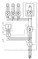
図1に、実施例による電源装置10、及び電源装置10に接続される機器のブロック図を示す。交流電源50から電源装置10の交流入力端子11に交流電力が供給される。交流電源50として、三相交流電源、例えば系統電源、エンジンで駆動される発電機等を用いることができる。電源装置10は、例えばガントリークレーンシステムの門型フレームに搭載される。
FIG. 1 is a block diagram of a
交流入力端子11に供給された交流電力が、交流母線12介して双方向インバータ13の交流側端子に接続されている。双方向インバータ13の直流側端子が、直流母線14を介して蓄電回路16に接続されている。2本の直流母線14の間に平滑コンデンサ15が接続されている。蓄電回路16は、DC/DCコンバータ17及び蓄電装置18を含む。蓄電装置18は、DC/DCコンバータ17を介して直流母線14に接続されている。蓄電装置18として、充放電可能な鉛蓄電池、リチウムイオン二次電池等を用いることができる。蓄電装置18は、DC/DCコンバータ17を介して、直流母線14に対して充放電を行う。
AC power supplied to the
交流母線12と直流母線14との間に挿入された双方向インバータ13は、交流母線12に供給されている交流電力を直流に変換して直流母線14に供給する動作(以下、充電動作という。)と、直流母線14に供給されている直流電力を交流電力に変換して交流母線12に供給する動作(以下、放電動作という。)との双方向動作を行うことができる。
The
交流母線12に第1の開閉器20が挿入されている。第1の開閉器20として、補助接点付きの配線保護用遮断器(MCCB)を用いることができる。補助接点20aの導通状態が、第1の開閉器20の開閉状態に応じて切り替わる。補助接点20aの導通状態を読み取ることにより、第1の開閉器20の開閉状態を検出することができる。
A
第1の開閉器20と双方向インバータ13との間の交流母線12に、交流出力端子21が設けられている。交流出力端子21に、操縦室の照明や空調機等の交流負荷(補機)22が接続される。
An
直流母線14に、複数の直流出力端子、例えば3対の直流出力端子25、26、27が設けられている。これらの直流出力端子に、クレーンシステムの動力源であるモータが接続される。例えば直流出力端子25に、インバータ31を介して巻上げモータ35が接続され、直流出力端子26に、インバータ32を介して横行用モータ36が接続され、直流出力端子27に、インバータ33を介して走行用モータ37が接続されている。
The direct
次に、実施例による電源装置の巻上げモータ35、横行用モータ36、及び走行用モータ37への電力供給系統について説明する。
Next, the power supply system to the hoisting
交流電源50から供給された交流電力が、双方向インバータ13で直流電力に変換された後、インバータ31、32、33に供給される。インバータ31、32、33は、直流電力を交流電力に変換し、それぞれ巻上げモータ35、横行用モータ36、及び走行用モータ37に交流電力を供給する。
AC power supplied from the
フックを降下させるとき、巻上げモータ35が回生電力を発生する。この回生電力は、インバータ31、直流母線14、及びDC/DCコンバータ17を経由して蓄電装置18に供給され、蓄電装置18が充電される。蓄電装置18の充電状態(SOC)が十分高い場合には、蓄電装置18を放電させて、放電電力を直流母線14に供給してもよい。
When the hook is lowered, the winding
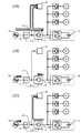
次に、図2A〜図2Cを参照して、交流負荷22への電力供給系統について説明する。図2A〜図2Cでは、交流母線12及び直流母線14を、それぞれ1本の線で表している。
Next, a power supply system to the
図2Aに、交流電源50から交流母線12に交流電力が供給されているときの電力の流れを示す。正常動作時に、第1の開閉器20はオンになっている。交流電源50から供給された交流電力が、交流母線12を経由して交流負荷22に供給される。
FIG. 2A shows the flow of power when AC power is supplied from the
双方向インバータ13は、連系運転される。一例として、蓄電装置18の充電状態が低下している場合には、双方向インバータ13は充電動作を行う。充電動作によって直流母線14に電力が供給され、この電力によって、蓄電装置18が充電される。蓄電装置18の充電状態が十分高い場合には、蓄電装置18を放電させて直流母線14に直流電力を供給する。さらに、双方向インバータ13は、放電動作を行う。放電動作によって交流母線12に電力が供給される。交流母線12に供給された電力によって交流負荷22が駆動される。このように、連系運転時には、双方向インバータ13の動作状態が、電気負荷に要求される電力、蓄電装置18の充電状態等によって、充電動作と放電動作との間で切り替わる。
The
図2Bに、交流電源50からの交流電力の供給が停止したときの電力の流れを示す。この時点で、第1の開閉器20はオンのままである。交流電源50からの交流電力の供給が停止すると、双方向インバータ13は連系運転を停止させる。また、第1の開閉器20がオンの時には、双方向インバータ13は、自立運転も行わない。「自立運転」とは、交流負荷22の要求電力に応じて放電動作を実行することにより、交流負荷22に電力を供給する運転を意味する。自立運転が行われないため、交流負荷22への電力の供給も停止する。なお、連系運転時の放電動作において、交流母線12に供給される交流電力は、交流負荷の要求電力とは無関係であり、蓄電装置18の充電状態等によって決まる。
FIG. 2B shows the flow of power when the supply of AC power from the
図2Cに、第1の開閉器20がオフにされたときの電力の流れを示す。第1の開閉器20は、例えば停電を確認したオペレータによって操作されて、オフにされる。双方向インバータ13が第1の開閉器20の開閉状態を読み取り、第1の開閉器20がオフにされたことを検出する。第1の開閉器20がオフにされたことを検出すると、双方向インバータ13は自立運転を開始する。具体的には、双方向インバータ13は、交流負荷22に要求される電力に応じて放電動作を行う。交流母線12に供給された電力により、交流負荷22が駆動される。直流母線14の電圧が低下すると、DC/DCコンバータ17が蓄電装置18の電圧を昇圧して、蓄電装置18から直流母線14に電力を供給する。
FIG. 2C shows the flow of electric power when the
双方向インバータ13は、スイッチング素子をオンオフ制御するパルス幅変調信号により、交流母線12に供給する交流電力の電圧及び周波数を制御することができる。自立運転時には、双方向インバータ13は、直流電力を交流電力に変換するに際し、交流負荷(補機)22を駆動するために適切な電圧及び周波数の交流電力を、交流母線12に供給する。このため、交流負荷22が系統電源等の交流電源50に接続されていない状態でも、ほぼ定格通りの適切な交流電力によって交流負荷22を駆動することができる。
The
双方向インバータ13は、第1の開閉器20がオフにされたことを検出した時点で、自動的に自立運転を開始する構成としてもよいし、オペレータによる自立運転開始のスイッチ操作を待って自立運転を開始する構成としてもよい。なお、第1の開閉器20がオンの時には、オペレータによる自立運転開始のスイッチ操作があっても、自立運転は行わない。
The
次に、図3に示した比較例と対比しつつ、上記実施例の優れた効果について説明する。
図3に、比較例による電源装置、及び電源装置に接続された機器のブロック図を示す。図1に示した実施例では、交流負荷22が交流母線12に接続されていたが、図3に示した比較例では、交流負荷22が、交流安定化電源19を介して直流母線14に接続されている。さらに、比較例においては、第1の開閉器20(図1)が設けられていない。交流安定化電源19は、直流電力を、一定電圧一定周波数の交流電力に変換する。比較例において、停電時には、双方向インバータ13の運転が停止される。その他の構成は、図1に示した実施例と図3に示した比較例とで同一である。
Next, the superior effect of the above-described embodiment will be described in comparison with the comparative example shown in FIG.
FIG. 3 shows a block diagram of a power supply device according to a comparative example and devices connected to the power supply device. In the embodiment shown in FIG. 1, the
図3に示した比較例のように、交流負荷22を直流母線14に接続する場合には、直流を交流に変換する交流安定化電源19が必要であるが、実施例の場合には、交流安定化電源回路が不要である。実施例においては、双方向インバータ13が自立運転することにより、交流安定化電源と同等の役割を担う。
When the
上述のように、実施例においては、双方向インバータ13が自立運転することにより、交流母線12に接続された交流負荷22に電力を供給することができる。
As described above, in the embodiment, power can be supplied to the
また、停電時に、第1の開閉器20がオンの状態で双方向インバータ13が自立運転すると、第1の開閉器20よりも交流電源50側の交流母線12に電圧が印加されてしまう。交流電源50が動作していないときに、電源装置10から交流電源50側に電力を供給する運転を「単独運転」という。
In addition, when the
双方向インバータ13が単独運転状態になると、種々の不都合が生じ得る。例えば、地絡事故によって交流電源50からの電力供給が停止した場合に、双方向インバータ13が単独運転されると、地絡点への電力供給が継続してしまう。また、交流電源50側で電気工事が行われている場合には、停電と想定される箇所に電力が供給されてしい、作業員が危険にさらされる。
When the
上記実施例では、停電状態でも、第1の開閉器20がオンのとき(図2B)には、双方向インバータ13は連系運転も自立運転も行わず、待機状態になる。このため、交流電源50側に電力が供給されることはない。
In the above embodiment, even when the
次に、図4を参照して、他の実施例による電源装置について説明する。以下、図1に示した実施例との相違点について説明し、共通の構成については説明を省略する。 Next, a power supply device according to another embodiment will be described with reference to FIG. Hereinafter, differences from the embodiment shown in FIG. 1 will be described, and descriptions of common configurations will be omitted.
図4に、本実施例による電源装置10、及び電源装置10に接続される機器のブロック図を示す。図1に示した実施例では、双方向インバータ13が第1の開閉器20の開閉状態を読み取ったが、図4に示した実施例では、制御装置40が第1の開閉器20の開閉状態を読み取る。制御装置40は、第1の開閉器20がオンの時には、双方向インバータ13に対して自立運転を禁止する指令を送出し、第1の開閉器20がオフの時には、双方向インバータ13に対して自立運転の実行を許可する司令を送出する。
FIG. 4 is a block diagram of the
双方向インバータ13は、交流電源50からの電力の供給が停止すると、連系運転を停止する。制御装置40から自立運転の禁止が指令されている期間は、双方向インバータ13は自立運転を行わない。制御装置40から自立運転の実行を許可する指令を受けると、双方向インバータ13は自立運転を開始する。
When the supply of power from the
図4に示した実施例においても、図1に示した実施例と同様の効果が得られる。 Also in the embodiment shown in FIG. 4, the same effect as that of the embodiment shown in FIG. 1 can be obtained.
次に、図5を参照して、さらに他の実施例による電源装置について説明する。以下、図1に示した実施例との相違点について説明し、共通の構成については説明を省略する。 Next, a power supply device according to still another embodiment will be described with reference to FIG. Hereinafter, differences from the embodiment shown in FIG. 1 will be described, and descriptions of common configurations will be omitted.
図5に、本実施例による電源装置10、及び電源装置10に接続される機器のブロック図を示す。図5に示した実施例においては、交流母線12と交流出力端子21との間に第2の開閉器28が挿入されている。第2の開閉器28として、例えば補助接点付きの配線保護用遮断器(MCCB)を用いることができる。双方向インバータ13が、補助接点を介して第2の開閉器28の開閉状態を読み取る。
FIG. 5 shows a block diagram of the
次に、図6A〜図6Cを参照して、図5に示した実施例による電源装置の動作について説明する。図6A〜図6Cは、いずれも交流電源50からの電力の供給が停止した状態を示している。
Next, the operation of the power supply apparatus according to the embodiment shown in FIG. 5 will be described with reference to FIGS. 6A to 6C. 6A to 6C each show a state where the supply of power from the
図6Aに示すように、第1の開閉器20がオンのときには、第2の開閉器28の開閉状態にかかわらず、双方向インバータ13は図1に示した実施例と同様に、自立運転を行わない。
As shown in FIG. 6A, when the
図6Bに示すように、第1の開閉器20がオフであっても、第2の開閉器28がオフのときには、双方向インバータ13は自立運転を行わない。
As shown in FIG. 6B, even when the
図6Cに示すように、第1の開閉器20がオフであり、かつ第2の開閉器28がオンのときに、双方向インバータ13は自立運転を行う。
As shown in FIG. 6C, when the
第2の開閉器28がオフであるということは、交流負荷22を動作させる必要がないことを意味する。図5に示した実施例においては、交流負荷22を動作させる必要がないときに、双方向インバータ13が自立運転することを回避することができる。さらに、交流負荷22に短絡故障や漏電故障等の何らかの故障が発生している場合にも、第2の開閉器28がオフにされる。図5に示した実施例においては、交流負荷22に故障が発生しているときに、交流負荷22への電力の供給を回避することができる。
The fact that the
次に、図7を参照して、さらに他の実施例による電源装置について説明する。以下、図5に示した実施例との相違点について説明し、共通の構成については説明を省略する。 Next, a power supply device according to still another embodiment will be described with reference to FIG. Hereinafter, differences from the embodiment shown in FIG. 5 will be described, and description of common configurations will be omitted.
図7に、本実施例による電源装置10、及び電源装置10に接続される機器のブロック図を示す。図7に示した実施例による電源装置10は、第1の開閉器20及び第2の開閉器28の他に、第3の開閉器29を有する。第3の開閉器29を介して、第1の開閉器20よりも交流電源50側の交流母線12と交流出力端子21とが接続される。第2の開閉器28と第3の開閉器29とはインターロックされており、両者が同時にオンになることはない。
FIG. 7 is a block diagram of the
図7に示した実施例においても、第1の開閉器20及び第2の開閉器28の開閉状態と、双方向インバータ13の運転状態との関係は、図5に示した実施例の場合と同様である。図7に示した実施例では、交流電源50が電源装置10に電力を供給しているときに、何らかの原因で第1の開閉器20がオフになっているとき、第3の開閉器29をオンにすることにより、交流電源50から交流負荷22に電力を供給することができる。
Also in the embodiment shown in FIG. 7, the relationship between the open / close state of the
上記実施例では、電源装置10がガントリークレーンシステムに搭載されていたが、他のクレーンシステム、たとえばタイヤマウント式ジブクレーンシステム等に搭載することも可能である。さらに、電動モータ、蓄電装置、及び補機を有する他の作業機械に搭載することも可能である。
In the above-described embodiment, the
以上実施例に沿って本発明を説明したが、本発明はこれらに制限されるものではない。例えば、種々の変更、改良、組み合わせ等が可能なことは当業者に自明であろう。 Although the present invention has been described with reference to the embodiments, the present invention is not limited thereto. It will be apparent to those skilled in the art that various modifications, improvements, combinations, and the like can be made.
10 電源装置
11 交流入力端子
12 交流母線
13 双方向インバータ
14 直流母線
15 平滑コンデンサ
16 蓄電回路
17 DC/DCコンバータ
18 蓄電装置
19 交流安定化電源(CVCF)
20 第1の開閉器
21 交流出力端子
22 交流負荷
25、26、27 直流出力端子
28 第2の開閉器
29 第3の開閉器
31、32、33 インバータ
35 巻上げモータ
36 横行用モータ
37 走行用モータ
40 制御装置
50 交流電源
DESCRIPTION OF
20
Claims (9)
交流電力が与えられる交流母線と前記直流母線との間に挿入され、前記交流母線から前記直流母線に電力を供給する動作と、前記直流母線から前記交流母線に電力を供給する動作との双方向動作を行う双方向インバータと、
前記交流母線に挿入された第1の開閉器と、
前記第1の開閉器と前記双方向インバータとの間の前記交流母線に設けられ、交流電力で駆動される補機が接続される交流出力端子と
を有し、
前記双方向インバータは、前記交流母線への交流電力の供給が停止し、かつ前記第1の開閉器がオフの場合に、前記直流母線から前記交流母線に電力を供給し、前記交流母線への交流電力の供給が停止しても、前記第1の開閉器がオンの場合には、前記交流母線へ電力を供給しない電源装置。 A power storage device connected to a DC bus and charging / discharging the DC bus;
Bidirectional operation of inserting power between the AC bus to which the AC power is applied and the DC bus and supplying power from the AC bus to the DC bus and supplying power from the DC bus to the AC bus A bidirectional inverter that performs the operation;
A first switch inserted in the AC bus;
An AC output terminal provided on the AC bus between the first switch and the bidirectional inverter, to which an auxiliary machine driven by AC power is connected;
The bidirectional inverter supplies power from the DC bus to the AC bus when supply of AC power to the AC bus is stopped and the first switch is off, A power supply device that does not supply power to the AC bus when the first switch is on even if the supply of AC power is stopped.
前記制御装置は、前記交流母線への交流電力の供給が停止し、かつ前記第1の開閉器がオンのとき、前記双方向インバータに、前記直流母線から前記交流母線に電力を供給する動作を禁止させ、前記第1の開閉器がオフのとき、前記双方向インバータに、前記直流母線から前記交流母線に電力を供給する動作を許可する請求項1乃至4のいずれか1項に記載の電源装置。 And a control device for giving an operation command to the bidirectional inverter,
The controller is configured to supply power to the bidirectional inverter from the DC bus to the AC bus when the supply of AC power to the AC bus is stopped and the first switch is on. 5. The power supply according to claim 1, wherein the power supply is prohibited and permits the bidirectional inverter to perform an operation of supplying power from the DC bus to the AC bus when the first switch is off. 6. apparatus.
Priority Applications (1)
| Application Number | Priority Date | Filing Date | Title |
|---|---|---|---|
| JP2016065543A JP2017184366A (en) | 2016-03-29 | 2016-03-29 | Power supply device |
Applications Claiming Priority (1)
| Application Number | Priority Date | Filing Date | Title |
|---|---|---|---|
| JP2016065543A JP2017184366A (en) | 2016-03-29 | 2016-03-29 | Power supply device |
Publications (1)
| Publication Number | Publication Date |
|---|---|
| JP2017184366A true JP2017184366A (en) | 2017-10-05 |
Family
ID=60007823
Family Applications (1)
| Application Number | Title | Priority Date | Filing Date |
|---|---|---|---|
| JP2016065543A Pending JP2017184366A (en) | 2016-03-29 | 2016-03-29 | Power supply device |
Country Status (1)
| Country | Link |
|---|---|
| JP (1) | JP2017184366A (en) |
Cited By (4)
| Publication number | Priority date | Publication date | Assignee | Title |
|---|---|---|---|---|
| JP2019009969A (en) * | 2017-06-28 | 2019-01-17 | 株式会社ダイヘン | Switching device and power conditioner system |
| WO2019208147A1 (en) * | 2018-04-23 | 2019-10-31 | 京セラ株式会社 | Electricity storage device, electricity storage device control device, and electricity storage device control method |
| CN112703657A (en) * | 2018-09-13 | 2021-04-23 | Ls电气株式会社 | Power supply device and power supply system |
| US12095308B2 (en) | 2018-09-13 | 2024-09-17 | Ls Electric Co., Ltd. | Power supply device and power supply system |
-
2016
- 2016-03-29 JP JP2016065543A patent/JP2017184366A/en active Pending
Cited By (5)
| Publication number | Priority date | Publication date | Assignee | Title |
|---|---|---|---|---|
| JP2019009969A (en) * | 2017-06-28 | 2019-01-17 | 株式会社ダイヘン | Switching device and power conditioner system |
| WO2019208147A1 (en) * | 2018-04-23 | 2019-10-31 | 京セラ株式会社 | Electricity storage device, electricity storage device control device, and electricity storage device control method |
| JPWO2019208147A1 (en) * | 2018-04-23 | 2021-04-01 | 京セラ株式会社 | Power storage device, control device of power storage device, control method of power storage device |
| CN112703657A (en) * | 2018-09-13 | 2021-04-23 | Ls电气株式会社 | Power supply device and power supply system |
| US12095308B2 (en) | 2018-09-13 | 2024-09-17 | Ls Electric Co., Ltd. | Power supply device and power supply system |
Similar Documents
| Publication | Publication Date | Title |
|---|---|---|
| US11207993B2 (en) | Storage-battery charging device for a motor vehicle, method for operating an on-board storage-battery charging device, high-voltage vehicle electrical system and use of a storage-battery charging device | |
| KR101171908B1 (en) | System of dc link pre-recharge for plug-in hybrid vehicle | |
| US20190359072A1 (en) | Power supply system for vehicle | |
| KR20170065741A (en) | Method and system of controlling vehicle electric power for jump start | |
| JP6439282B2 (en) | Charging system, power supply vehicle, charging vehicle, and charging method | |
| US10680546B2 (en) | Motor drive device including power storage unit, and motor drive system | |
| WO2018163494A1 (en) | Vehicle power supply device | |
| JP2014099986A (en) | Composite power storage system | |
| JP6884922B2 (en) | Power converter | |
| WO2017169665A1 (en) | Power conditioner, power supply system, and current control method | |
| JP2017184366A (en) | Power supply device | |
| EP3447899A1 (en) | Uninterruptible power supply device | |
| JP6829069B2 (en) | Circuit system for railroad vehicles | |
| WO2011004588A1 (en) | Electric vehicle control device | |
| JP6491967B2 (en) | Charge control device for hybrid railway vehicle | |
| US20160288649A1 (en) | Vehicle and charging and discharging system using vehicle | |
| JP5788472B2 (en) | elevator | |
| WO2019208383A1 (en) | Power supply system for electric motor car | |
| JP2017225323A (en) | Power storage system | |
| JP2008283729A (en) | Uninterruptible power system | |
| JP6746046B1 (en) | Power converter | |
| JP2009027868A (en) | Step-up/down converter | |
| JP6815762B2 (en) | Power conversion system | |
| WO2022091309A1 (en) | Electricity storage machine | |
| JP4142241B2 (en) | On-site power generation system |