JP2017185043A - Gas fire extinguishing system with non-return valve in the starting gas line - Google Patents
Gas fire extinguishing system with non-return valve in the starting gas line Download PDFInfo
- Publication number
- JP2017185043A JP2017185043A JP2016076474A JP2016076474A JP2017185043A JP 2017185043 A JP2017185043 A JP 2017185043A JP 2016076474 A JP2016076474 A JP 2016076474A JP 2016076474 A JP2016076474 A JP 2016076474A JP 2017185043 A JP2017185043 A JP 2017185043A
- Authority
- JP
- Japan
- Prior art keywords
- gas
- valve
- pressure
- starting
- fire extinguishing
- Prior art date
- Legal status (The legal status is an assumption and is not a legal conclusion. Google has not performed a legal analysis and makes no representation as to the accuracy of the status listed.)
- Granted
Links
Images


Landscapes
- Fire-Extinguishing By Fire Departments, And Fire-Extinguishing Equipment And Control Thereof (AREA)
- Safety Valves (AREA)
Abstract
【課題】複数の不還弁を起動用ガス管路に直列状態で介在させた場合でも、各不還弁の位置で起動用ガスの圧力が低下せず、起動用ガス管路の末端の圧力を維持して、容器弁の作動の安定性が確保することができるようにした起動用ガス管路に不還弁を介在させたガス系消火システムを提供すること。【解決手段】起動用ガス管路における起動用ガスの流通方向を制限する不還弁に、1次側のガス圧と2次側のガス圧とに圧力差が生じない不還弁V1を用いる。【選択図】図3[Problem] To provide a gas-based fire extinguishing system with non-return valves interposed in a startup gas pipeline, so that even when multiple non-return valves are interposed in series in the startup gas pipeline, the pressure of the startup gas does not drop at the position of each non-return valve, maintaining the pressure at the end of the startup gas pipeline and ensuring stable operation of the container valve. [Solution] The non-return valve that limits the flow direction of the startup gas in the startup gas pipeline uses a non-return valve V1 that does not create a pressure difference between the gas pressure on the primary side and the gas pressure on the secondary side. [Selected drawing] Figure 3
Description
本発明は、起動回路に不還弁を介在させたガス系消火システムに関するものである。 The present invention relates to a gas fire extinguishing system in which a nonreturn valve is interposed in a starting circuit.
従来、消火剤として、ハロン、窒素、二酸化炭素等のガス系消火剤を用いるガス系消火システムにおいて、1つのガス系消火システムを用いて、容積が異なる複数の消火対象区画の消火を行うようにしたものがある(例えば、特許文献1参照。)。 Conventionally, in a gas fire extinguishing system using a gas fire extinguishing agent such as halon, nitrogen, carbon dioxide, etc. as a fire extinguishing agent, one gas fire extinguishing system is used to extinguish a plurality of fire extinguishing target sections having different volumes. (For example, refer to Patent Document 1).
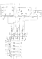
このガス系消火システムは、例えば、図1に示すように、5本の消火剤貯蔵容器1−1、1−2、・・・1−5を備え、各容器1には、容器弁2を介して連結管3を接続し、さらに連結管3を1本の集合管4に接続し、この集合管4を各消火対象区画6−1、6−2、6−3まで延設した主配管5−1、5−2、5−3に接続する。主配管5−1、5−2、5−3には、選択弁9−1、9−2、9−3を配設し、消火対象区画6−1、6−2、6−3に選択的にガス系消火剤を送るようにする。消火対象区画6−1、6−2、6−3まで延設した主配管5−1、5−2、5−3を、消火対象区画6−1、6−2、6−3内にそれぞれ配設した枝管8−1、8−2、8−3に接続し、この枝管8−1、8−2、8−3を消火対象区画6−1、6−2、6−3内の適所に複数個配設した噴射ヘッド7−1、7−2、7−3に接続する。 The gas fire extinguishing system includes, for example, five fire extinguishing agent storage containers 1-1, 1-2,... 1-5 as shown in FIG. The connecting pipe 3 is connected to the main pipe, and the connecting pipe 3 is further connected to one collecting pipe 4, and this collecting pipe 4 is extended to each fire extinguishing target section 6-1, 6-2, 6-3. Connect to 5-1, 5-2, 5-3. Selection valves 9-1, 9-2, and 9-3 are arranged in the main pipes 5-1, 5-2, and 5-3, and are selected as the fire extinguishing target sections 6-1, 6-2, and 6-3. To send a gas fire extinguisher. The main pipes 5-1, 5-2, and 5-3 extended to the fire extinguishing target sections 6-1, 6-2, and 6-3 are respectively placed in the fire extinguishing target sections 6-1, 6-2, and 6-3. Connected to the arranged branch pipes 8-1, 8-2, 8-3, and the branch pipes 8-1, 8-2, 8-3 are placed in the fire extinguishing target sections 6-1, 6-2, 6-3. Are connected to a plurality of jetting heads 7-1, 7-2, and 7-3 disposed at appropriate positions.
この場合、消火対象区画6−1、6−2、6−3は、その容積が異なるため、消火するのに必要となるガス系消火剤の量も異なる。このため、主配管5−1、5−2、5−3の口径を各消火対象区画6−1、6−2、6−3の容積に応じて異ならせるほか、火災発生時に、消火対象となる消火対象区画6−1、6−2、6−3に対応した本数の消火剤貯蔵容器1が開放されるようにガス系消火システムを構成する。 In this case, the fire extinguishing target sections 6-1, 6-2, and 6-3 have different volumes, so that the amounts of gas-based fire extinguishing agents necessary for extinguishing fires are also different. For this reason, the diameters of the main pipes 5-1, 5-2, and 5-3 are changed according to the volumes of the respective fire extinguishing target sections 6-1, 6-2, and 6-3. The gas fire extinguishing system is configured so that the number of fire extinguishing agent storage containers 1 corresponding to the fire extinguishing target sections 6-1, 6-2 and 6-3 are opened.
ここで、開放すべき消火剤貯蔵容器1の本数を、消火対象区画6−1が5本、消火対象区画6−2が3本、消火対象区画6−3が1本に設定する場合について説明する。
なお、図中、9−1、9−2、9−3は選択弁、10−1、10−2、10−3は選択弁開放装置、11−1、11−2、11−3は起動用ガス容器、12−1、12−2、12−3は起動用ガス容器開放用のソレノイドである。また、図中、13−1、13−2、13−3は、選択弁9−1、9−2、9−3及び起動用ガス容器11−1、11−2、11−3の開放をコントロールする起動用ガス管路で、選択弁開放装置10−1、10−2、10−3に接続され、その途中の適所に不還弁14−1、14−2、14−3、14−A、14−Bを配設する。なお、不還弁14−1、14−2、14−3、14−A、14−Bの通過可能方向は、図の矢印の向きで表している。なお、これらの部材の末尾の数字1、2、3は、消火対象区画の末尾の数字1、2、3にそれぞれ対応している。
Here, the case where the number of extinguishing agent storage containers 1 to be opened is set to five for the extinguishing target section 6-1, three for the extinguishing target section 6-2, and one for the extinguishing target section 6-3 will be described. To do.
In the figure, 9-1, 9-2 and 9-3 are selection valves, 10-1, 10-2 and 10-3 are selection valve opening devices, and 11-1, 11-2 and 11-3 are activated. Gas containers 12-1, 12-2, and 12-3 are solenoids for opening the starting gas container. In the figure, reference numerals 13-1, 13-2, and 13-3 indicate that the selection valves 9-1, 9-2, and 9-3 and the starting gas containers 11-1, 11-2, and 11-3 are opened. It is connected to the selective valve opening devices 10-1, 10-2, 10-3 by a starting gas pipeline to be controlled, and non-return valves 14-1, 14-2, 14-3, 14- A and 14-B are disposed. In addition, the passable direction of the non-return valves 14-1, 14-2, 14-3, 14-A, 14-B is represented by the direction of the arrow in the figure. The
そして、消火対象区画6−1に火災が発生したとすれば、火災発見者がこの消火対象区画6−1に対応する押釦(手動操作の場合)を操作すると、電気信号が起動用ガス容器開放用のソレノイド12−1に送られ、ソレノイド12−1が動作して起動用ガス容器11−1が開放される。起動用ガス容器11−1が開放されることにより放出された起動用ガス(起動用ガスのガス圧:周囲温度や管容積にもよるが、概ね1〜11MPaに設定)は、まず、選択弁開放装置10−1に導入されて選択弁9−1を開放してから、不還弁14−1を経て起動用ガス管路13−1を通り、不還弁14−A及び不還弁14−Bを通過してすべての容器弁2に至って消火剤貯蔵容器1を5本とも開放する。このとき、不還弁14−2及び不還弁14−3を通過することができないため、選択弁9−2及び選択弁9−3は開放されない。そして、開放された5本の消火剤貯蔵容器1から、ガス系消火剤が、容器弁2、連結管3、集合管4、選択弁9−1、主配管5−1及び枝管8−1を介して噴射ヘッド7−1まで送られ、噴射ヘッド7−1から消火対象区画6−1内に放出される。
If a fire occurs in the fire extinguishing target section 6-1 and the fire finder operates the push button (in the case of manual operation) corresponding to the fire extinguishing target section 6-1, the electrical signal is opened to the start gas container. The solenoid 12-1 is operated and the activation gas container 11-1 is opened. The starting gas released by opening the starting gas container 11-1 (the gas pressure of the starting gas: depending on the ambient temperature and the tube volume, which is generally set to 1 to 11 MPa) is selected first. After being introduced into the opening device 10-1 and opening the selection valve 9-1, it passes through the nonreturn valve 14-1 through the starting gas line 13-1, the nonreturn valve 14 -A and the
また、消火対象区画6−2に火災が発生したとすれば、火災発見者がこの消火対象区画6−2に対応する押釦(手動操作の場合)を操作すると、電気信号が起動用ガス容器開放用のソレノイド12−2に送られ、ソレノイド12−2が動作して起動用ガス容器11−2が開放される。起動用ガス容器11−2が開放されることにより放出された起動用ガスは、まず、選択弁開放装置10−2に導入されて選択弁9−2を開放してから、不還弁14−2を経て起動用ガス管路13−2を通り、不還弁14−Bを通過して容器弁2に至って消火剤貯蔵容器1を3本だけ、すなわち、消火剤貯蔵容器1−3、1−4、1−5を開放する。このとき、不還弁14−Aを通過することができないため、消火剤貯蔵容器1のうち2本、すなわち、消火剤貯蔵容器1−1、1−2は開放されない。また、不還弁14−1及び不還弁14−3を通過することができないため、選択弁9−1及び選択弁9−3は開放されない。そして、開放された3本の消火剤貯蔵容器1−3、1−4、1−5から、ガス系消火剤が、容器弁2、連結管3、集合管4、選択弁9−2、主配管5−2及び枝管8−2を介して噴射ヘッド7−2まで送られ、噴射ヘッド7−2から消火対象区画6−2内に放出される。
Further, if a fire has occurred in the fire extinguishing target section 6-2, when the fire finder operates a push button (in the case of manual operation) corresponding to the fire extinguishing target section 6-2, an electrical signal is opened to the start gas container. Is sent to the solenoid 12-2 for operation, and the solenoid 12-2 is operated to open the starting gas container 11-2. The starting gas released by opening the starting gas container 11-2 is first introduced into the selective valve opening device 10-2 to open the selective valve 9-2, and then the
また、消火対象区画6−3に火災が発生したとすれば、火災発見者がこの消火対象区画6−3に対応する押釦(手動操作の場合)を操作すると、電気信号が起動用ガス容器開放用のソレノイド12−3に送られ、ソレノイド12−3が動作して起動用ガス容器11−3が開放される。起動用ガス容器11−3が開放されることにより放出された起動用ガスは、まず、選択弁開放装置10−3に導入されて選択弁9−3を開放してから、不還弁14−3を経て起動用ガス管路13−3を通り、容器弁2に至って消火剤貯蔵容器1を1本だけ、すなわち、消火剤貯蔵容器1−5を開放する。このとき、不還弁14−Bを通過することができない(したがって、当然、不還弁14−Aも通過することができない)ため、消火剤貯蔵容器1のうち4本、すなわち、消火剤貯蔵容器1−1、1−2、1−3、1−4は開放されない。また、不還弁14−1及び不還弁14−2を通過することができないため、選択弁9−1及び選択弁9−2は開放されない。そして、開放された1本の消火剤貯蔵容器1−5から、ガス系消火剤が、容器弁2、連結管3、集合管4、選択弁9−3、主配管5−3及び枝管8−3を介して噴射ヘッド7−3まで送られ、噴射ヘッド7−3から消火対象区画6−3内に放出される。
Also, if a fire has occurred in the fire extinguishing target section 6-3, when the fire finder operates a push button (in the case of manual operation) corresponding to the fire extinguishing target section 6-3, the electrical signal is released from the start gas container. Is sent to the solenoid 12-3 for operation, and the solenoid 12-3 operates to open the starting gas container 11-3. The starting gas released by opening the starting gas container 11-3 is first introduced into the selection valve opening device 10-3 to open the selection valve 9-3, and then the
ここでは、消火対象区画が3区画で、消火剤貯蔵容器1の本数が5本の場合を例にして説明したが、消火対象区画の数及び消火剤貯蔵容器1の本数並びに開放される消火剤貯蔵容器1の本数は、任意に設定される。 Here, the case where there are three fire extinguishing target sections and the number of fire extinguishing agent storage containers 1 is described as an example, but the number of fire extinguishing target sections, the number of fire extinguishing agent storage containers 1 and the extinguishing agent to be opened are described. The number of the storage containers 1 is arbitrarily set.
ところで、上記従来のガス系消火システムにおいては、起動用ガス管路13−1、13−2、13−3における起動用ガスの流通方向を制限する不還弁14−1、14−2、14−3、14−A、14−Bに、構造が簡単で、動作の安定性が高い、図2に示すような構造の不還弁V0を用いるようにしている。 By the way, in the conventional gas fire extinguishing system, the non-return valves 14-1, 14-2, 14 for restricting the flow direction of the starting gas in the starting gas pipelines 13-1, 13-2, 13-3. -3, 14-A and 14-B are configured to use a non-return valve V0 having a simple structure and high operational stability as shown in FIG.
この不還弁V0は、1次側14aと2次側14bとを遮断可能に配設した、シート面14dを備えたピストン14cと、1次側14aに向けてピストン14cを付勢するばね14eと、起動用ガスの流路14f1、14f2とを備えて構成されている。
The non-return valve V0 includes a
次に、この不還弁V0は、以下のように動作する。
2次側14bから起動用ガスのガス圧がかかったとき、ピストン14cにかかるばね14eの付勢力とガス圧力によってシート面14dが弁座14gに押圧されることで、1次側14aと2次側14bとが遮断され、1次側14aには起動用ガスは流れない。
Next, the feedback valve V0 operates as follows.
When the gas pressure of the starting gas is applied from the
一方、1次側14aから起動用ガスのガス圧がかかったとき、ガス圧が、ばね14eがピストン14cを付勢する力以上の圧力であれば、ピストン14cが2次側14bに動き、流路14f1、14f2を通って2次側14bに起動用ガスが流れる。
ここで、1次側14aの起動用ガスのガス圧をP1、2次側14bの起動用ガスのガス圧をP2、1次側14aの起動用ガスのガス圧P1を受けるピストン14cの受圧面積をA1、2次側14bの起動用ガスのガス圧P2を受けるピストン14cの受圧面積をA2、弁座14gの直径をd1(面積をS1=π・d12/4)、ピストン14cの直径をd2(面積をS2=π・d22/4)、ばね14eの変位をx、ばね定数をkとする。
ピストン14cに働く力Fは、
F=P1・A1−P2・A2−kx
となる。
ピストンが動作を開始する条件は、初期状態がP2=0であり、A1=S1であるので、この不還弁V0では、
P1・S1−kx>0
のときに、ピストン14cが動作を開始する。
ピストン14cが動作を開始してから、2次側14bに起動用ガスが流れ込むことによって、P2の圧力が上昇していき、
P1・A1−P2・A2−kx=0
となったときに、ピストン14cの動きが停止し、平衡状態となる。その後P2の上昇に従って、ピストン14cが移動し、シート面14dが弁座14gに接して、1次側14aから2次側14bへの起動用ガスの流れが停止する。
この状態では、A1=A2=S1であるので、
P1−P2−kx/S1=0
となり、1次側14aの起動用ガスのガス圧P1と、2次側14bの起動用ガスのガス圧P2との間に、圧力差kx/S1(ただし、P1>P2)が発生する。
On the other hand, when the gas pressure of the starting gas is applied from the
Here, the pressure pressure area of the
The force F acting on the
F = P1, A1-P2, A2-kx
It becomes.
The conditions for starting the operation of the piston are that the initial state is P2 = 0 and A1 = S1, so in this non-return valve V0,
P1 · S1-kx> 0
At this time, the
Since the starting gas flows into the
P1, A1-P2, A2-kx = 0
When this happens, the movement of the
In this state, A1 = A2 = S1, so
P1-P2-kx / S1 = 0
Thus, a pressure difference kx / S1 (where P1> P2) is generated between the gas pressure P1 of the starting gas on the
このように、従来の起動用ガス管路13−1、13−2、13−3における起動用ガスの流通方向を制限する不還弁14−1、14−2、14−3、14−A、14−Bとして用いられている、不還弁V0は、構造が簡単で、動作の安定性が高い反面、平衡状態では、1次側14aの起動用ガスのガス圧P1と、2次側14bの起動用ガスのガス圧P2との間に、圧力差kx/S1(ただし、P1>P2)が発生するため、例えば、複数の不還弁V0を起動用ガス管路に直列状態で介在させた場合、各不還弁V0の位置で起動用ガスの圧力が低下していき、起動用ガス管路の末端の圧力が低くなり、容器弁2の作動の安定性が確保しにくくなることが考えられる。
Thus, the non-return valves 14-1, 14-2, 14-3, 14-A for restricting the flow direction of the starting gas in the conventional starting gas pipelines 13-1, 13-2, 13-3. The non-return valve V0 used as 14-B has a simple structure and high operational stability, but in equilibrium, the gas pressure P1 of the starting gas on the
本発明は、上記従来の起動用ガス管路に不還弁を介在させたガス系消火システムの有する問題点に鑑み、複数の不還弁を起動用ガス管路に直列状態で介在させた場合でも、各不還弁の位置で起動用ガスの圧力が低下せず、起動用ガス管路の末端の圧力を維持して、容器弁の作動の安定性が確保することができるようにした起動用ガス管路に不還弁を介在させたガス系消火システムを提供することを目的とする。 In view of the problem of the gas fire extinguishing system in which the non-return valve is interposed in the conventional starting gas pipe, the present invention has a case where a plurality of non-return valves are interposed in series in the starting gas pipe. However, the starting gas pressure does not decrease at the position of each non-return valve, and the pressure at the end of the starting gas line is maintained to ensure the stability of the operation of the container valve. An object of the present invention is to provide a gas fire extinguishing system in which a non-return valve is interposed in a gas pipeline.
上記目的を達成するため、本発明の起動用ガス管路に不還弁を介在させたガス系消火システムは、複数の消火剤貯蔵容器の各々に容器弁を配設し、該容器弁を、起動用ガスの流通方向を制限する不還弁を介在させた起動用ガス管路により接続し、火災発生時に、起動用ガス管路に起動用ガスを供給することで、容器弁を選択的に開放して、開放された容器弁に対応する消火剤貯蔵容器に貯蔵されているガス系消火剤を、容器弁及び管路を介して、消火対象区画に供給するようにした、起動用ガス管路に不還弁を介在させたガス系消火システムにおいて、前記不還弁に、1次側のガス圧と2次側のガス圧とに圧力差が生じない不還弁を用いたことを特徴とする。 In order to achieve the above object, a gas fire extinguishing system in which a non-return valve is interposed in a starting gas line of the present invention is provided with a container valve in each of a plurality of fire extinguishing agent storage containers, Connected by a starter gas line with a nonreturn valve that restricts the flow direction of the starter gas, and in the event of a fire, the starter gas is supplied to the starter gas line to selectively select the container valve. Gas pipe for starting which is opened and gas extinguishing agent stored in the extinguishing agent storage container corresponding to the opened container valve is supplied to the fire extinguishing target section through the container valve and the pipe line In the gas fire extinguishing system in which a non-return valve is interposed in the road, a non-return valve that does not cause a pressure difference between the primary side gas pressure and the secondary side gas pressure is used as the nonreturn valve. And
本発明の起動用ガス管路に不還弁を介在させたガス系消火システムによれば、複数の消火剤貯蔵容器の各々に容器弁を配設し、該容器弁を、起動用ガスの流通方向を制限する不還弁を介在させた起動用ガス管路により接続し、火災発生時に、起動用ガス管路に起動用ガスを供給することで、容器弁を選択的に開放して、開放された容器弁に対応する消火剤貯蔵容器に貯蔵されているガス系消火剤を、容器弁及び管路を介して、消火対象区画に供給するようにした、起動用ガス管路に不還弁を介在させたガス系消火システムにおいて、前記不還弁に、1次側のガス圧と2次側のガス圧とに圧力差が生じない不還弁を用いることにより、複数の不還弁を起動用ガス管路に直列状態で介在させた場合でも、各不還弁の位置で起動用ガスの圧力が低下せず、起動用ガス管路の末端の圧力を維持して、容器弁の作動の安定性が確保することができる。 According to the gas fire extinguishing system in which a nonreturn valve is interposed in the starting gas pipeline of the present invention, a container valve is disposed in each of a plurality of fire extinguishing agent storage containers, and the container valve is connected to the starting gas flow. Connected by a starting gas line with a non-return valve that restricts the direction, and in the event of a fire, by supplying the starting gas to the starting gas line, the container valve is selectively opened and opened. Non-return valve in the starting gas line that supplies the fire extinguisher stored in the fire extinguisher storage container corresponding to the container valve to the fire extinguishing target section via the container valve and the pipe line In the gas fire extinguishing system in which the non-return valve is used, a non-return valve that does not cause a pressure difference between the primary side gas pressure and the secondary side gas pressure is used as the nonreturn valve. Even when it is inserted in series in the starting gas line, the pressure of the starting gas decreases at the position of each non-return valve Not, to maintain the end pressure of the starting gas conduit, the stability of operation of the container valve can be secured.
以下、本発明の起動用ガス管路に不還弁を介在させたガス系消火システムの実施の形態を、図面に基づいて説明する。 Embodiments of a gas fire extinguishing system in which a nonreturn valve is interposed in a starting gas pipeline according to the present invention will be described below with reference to the drawings.
本発明の起動用ガス管路に不還弁を介在させたガス系消火システムは、図1に示す、ガス系消火システムと同様、消火剤として、ハロン、窒素、二酸化炭素等のガス系消火剤を用いるガス系消火システムにおいて、1つのガス系消火システムを用いて、容積が異なる複数の消火対象区画の消火を行うようにしたもので、複数の消火剤貯蔵容器1−1、1−2、・・・1−5の各々に容器弁2を配設し、この容器弁2を、起動用ガスの流通方向を制限する不還弁14−1、14−2、14−3、14−A、14−Bを介在させた起動用ガス管路13−1、13−2、13−3により接続し、火災発生時に、起動用ガス管路13−1、13−2、13−3に起動用ガスを供給することで、容器弁2を選択的に開放して、開放された容器弁2に対応する消火剤貯蔵容器1−1、1−2、・・・1−5に貯蔵されているガス系消火剤を、容器弁2及び管路(連結管3、集合管4、主配管5−1、5−2、5−3及び枝管8−1、8−2、8−3)を介して、消火対象区画6−1、6−2、6−3に供給するようにしたものである。
The gas fire extinguishing system in which a nonreturn valve is interposed in the starting gas pipe of the present invention is similar to the gas fire extinguishing system shown in FIG. In a gas-based fire extinguishing system using a single fire extinguishing system, a plurality of fire extinguishing target sections having different volumes are extinguished, and a plurality of extinguishing agent storage containers 1-1, 1-2, .. 1-5 are each provided with a
そして、本発明の起動用ガス管路に不還弁を介在させたガス系消火システムにおいては、起動用ガス管路13−1、13−2、13−3における起動用ガスの流通方向を制限する不還弁14−1、14−2、14−3、14−A、14−Bに、図3〜図5に示す、1次側のガス圧と2次側のガス圧とに圧力差が生じない不還弁V1、V2、V3、V4を用いるようにしている。 And in the gas fire extinguishing system in which the nonreturn valve is interposed in the starting gas line of the present invention, the flow direction of the starting gas in the starting gas lines 13-1, 13-2, 13-3 is restricted. To the non-return valves 14-1, 14-2, 14-3, 14-A, 14-B, the pressure difference between the primary side gas pressure and the secondary side gas pressure shown in FIGS. The non-return valves V1, V2, V3, and V4 that do not cause the problem are used.
これにより、本発明の起動用ガス管路に不還弁を介在させたガス系消火システムは、複数の不還弁を起動用ガス管路に直列状態で介在させた場合でも、各不還弁の位置で起動用ガスの圧力が低下せず、起動用ガス管路の末端の圧力を維持して、容器弁の作動の安定性が確保することができる。 As a result, the gas fire extinguishing system in which the nonreturn valve is interposed in the starting gas pipeline of the present invention is configured so that each nonreturn valve is provided even when a plurality of nonreturn valves are interposed in series in the starting gas pipeline. In this position, the pressure of the starting gas does not decrease, and the pressure at the end of the starting gas pipe is maintained, so that the stability of the operation of the container valve can be ensured.
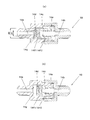
図3に示す、1次側のガス圧と2次側のガス圧とに圧力差が生じない不還弁V1は、1次側14aと2次側14bとを遮断可能に配設した、シート面14dを備えたピストン14cと、1次側14aに向けてピストン14cを付勢するばね14eと、起動用ガスの流路14fと、シール部14h1、14h2と、大気連通路14iとを備えて構成されている。また、弁座14gの直径をd1(面積をS1=π・d12/4)、シール部14h1、14h2部分の直径をそれぞれd2、d3(面積をS2=π・d22/4、S3=π・d32/4)とする。
The non-return valve V1 shown in FIG. 3 that does not cause a pressure difference between the primary side gas pressure and the secondary side gas pressure is disposed so that the
次に、この不還弁V1は、以下のように動作する。ここで、1次側14aの起動用ガスのガス圧をP1、2次側14bの起動用ガスのガス圧をP2、1次側14aの起動用ガスのガス圧P1を受けるピストン14cの受圧面積をA1、2次側14bの起動用ガスのガス圧P2を受けるピストン14cの受圧面積をA2、ばね14eの変位をx、ばね定数をkとする。
ピストン14cに働く力Fは、
F=P1・A1−P2・A2−kx
である。
2次側14bから起動用ガスのガス圧がかかったとき、P1=0、A2=S1−S2+S3であるから、
F=−P2・(S1−S2+S3)−kx<0
のとき、ピストン14cにかかるばね14eの付勢力とガス圧力によってシート面14dが弁座14gに押圧されることで、1次側14aと2次側14bとが遮断され、1次側14aには起動用ガスは流れないため、S1、S2、S3、kxは上式を満たすように設計される。特に、圧力とばね力を精密に設定しなくて済むように、S1−S2+S3>0となるように機器を設計する(例えば、d1=8mm、d2=12mm、d3=9mm)。
Next, the feedback valve V1 operates as follows. Here, the pressure pressure area of the
The force F acting on the
F = P1, A1-P2, A2-kx
It is.
When the gas pressure of the starting gas is applied from the
F = −P2 · (S1−S2 + S3) −kx <0
At this time, the
一方、1次側14aから起動用ガスのガス圧がかかったとき、ガス圧が、ばね14eがピストン14cを付勢する力以上の圧力であれば、ピストン14cが2次側14bに動き、流路14fを通って2次側14bに起動用ガスが流れる。
ピストンが動作を開始する条件は、初期状態がP2=0であり、A1=S1であるので、この不還弁V1では、
P1・S1−kx>0
のときに、ピストン14cが動作を開始する。
ピストン14cが動作を開始してから、2次側14bに起動用ガスが流れ込むことによって、P2の圧力が上昇していき、
P1・A1−P2・A2−kx=0
となったときに、ピストン14cの動きが停止し、平衡状態となるが、この不還弁V1では、その形状(2次側14bの起動用ガスのガス圧P2を受けるピストン14cの受圧面積A2は、大気連通路14iを介して大気圧がかかる部分だけ受圧面積が小さくなっている。)からA1>A2であるため、条件によっては平衡状態にならずピストン14cが2次側14bに圧力によって付勢され続け、ピストン14cが不還弁V1の弁本体部に当たることによって停止する。このときにピストンに働く力Fは、P1=P2であるので
F=P1・(S2−S3)-kx>0
となる。
上式を満たすとき、1次側14aの起動用ガスのガス圧P1と、2次側14bの起動用ガスのガス圧P2との間に、圧力差が発生しないようにすることができる。また、P1は起動用ガスであり十分に大きい値であるため、通常の使用においては上式を満たす。
On the other hand, when the gas pressure of the starting gas is applied from the
The conditions for starting the operation of the piston are that the initial state is P2 = 0 and A1 = S1, so in this non-return valve V1,
P1 · S1-kx> 0
At this time, the
Since the starting gas flows into the
P1, A1-P2, A2-kx = 0
When this happens, the movement of the
It becomes.
When the above equation is satisfied, it is possible to prevent a pressure difference from being generated between the gas pressure P1 of the starting gas on the
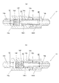
図4に示す、1次側のガス圧と2次側のガス圧とに圧力差が生じない不還弁V2は、1次側14aと2次側14bとを遮断可能に配設した、ピストン14cと、1次側14aに向けてピストン14cを付勢するばね14eと、起動用ガスの流路14fと、シール部14h1、14h2と、組み上げ時に閉空間となるピストン室14kとを備えて構成されている。
The non-return valve V2 shown in FIG. 4 that does not cause a pressure difference between the primary side gas pressure and the secondary side gas pressure is arranged so that the
次に、この不還弁V2は、以下のように動作する。
2次側14bから起動用ガスのガス圧がかかったとき、ピストン14cにかかるばね14eの付勢力によってピストン14cが図4(a)の位置から動かないため、ピストン14cよって1次側14aと2次側14bとが遮断され、1次側14aには起動用ガスは流れない。
Next, the non-return valve V2 operates as follows.
When the gas pressure of the starting gas is applied from the
一方、1次側14aから起動用ガスのガス圧がかかったとき、ガス圧が、ばね14eがピストン14cを付勢する力以上の圧力であれば、ピストン14cが2次側14bに動き、流路14fを通って2次側14bに起動用ガスが流れる。
ここで、1次側14aの起動用ガスのガス圧をP1、2次側14bの起動用ガスのガス圧をP2、ピストン室14k内の圧力をP3、1次側14aの起動用ガスのガス圧P1を受けるピストン14cの受圧面積をA1、2次側14bの起動用ガスのガス圧P2を受けるピストン14cの受圧面積をA2、ピストン室14k内の圧力P3を受けるピストン14cの受圧面積をA3、ピストン14cの先端部の直径をd1(面積をS1=π・d12/4)、ばね14eの変位をx、ばね定数をkとする。
ピストン14cに働く力Fは、
F=P1・A1−P3・A3−kx
である。
ピストン14cが動作を開始する条件は、初期状態がP3は組立時の圧力であるため、P3=0であり、A1=S1であるので
F=P1・S1−kx>0
のときに、ピストン14cが動作を開始する。
ピストン14cが動作を開始してから、ピストン14cの動作によって、ピストン室14kの容積が減少し、結果としてピストン室14k内の圧力が上昇する。
この不還弁V2では、その形状から、条件によっては平衡状態にならずピストン14cがP1の圧力によって付勢され続け、ピストン14cが不還弁V2の弁本体部に当たることによって停止する。このときに働く力FはA1=A3=S1であるので
F=P1・S1−P3・S1−kx>0
となる。
上式を満たすとき、1次側14aの起動用ガスのガス圧P1と、2次側14bの起動用ガスのガス圧P2との間に、圧力差が発生しないようにすることができる。ピストン14cの移動によってピストン室14kが減少する容積は十分に小さく、よって、ピストン室14k内の圧力は小さいものとなる。例えば、図4の関係において、容積は3011mm3から2703mm3に減少し、圧力は0から0.01MPaに上昇する。また、P1は起動用ガスであり十分に大きい値であるため、通常の使用においては上式を満たす。
On the other hand, when the gas pressure of the starting gas is applied from the
Here, the gas pressure of the startup gas on the
The force F acting on the
F = P1, A1-P3, A3-kx
It is.
The condition for starting the operation of the
At this time, the
After the
Due to its shape, the non-return valve V2 does not reach an equilibrium state depending on conditions, and the
It becomes.
When the above equation is satisfied, it is possible to prevent a pressure difference from being generated between the gas pressure P1 of the starting gas on the
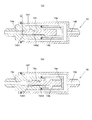
図5に示す、1次側のガス圧と2次側のガス圧とに圧力差が生じない不還弁V3は、1次側14aと2次側14bとを遮断可能に配設した、ピストン14cと、1次側14aに向けてピストン14cを付勢するばね14eと、起動用ガスの流路14fと、シール部14h1、14h2と、大気連通路14i、作動表示部Bとを備えて構成されている。
The non-return valve V3 shown in FIG. 5 that does not cause a pressure difference between the primary side gas pressure and the secondary side gas pressure is disposed so that the
次に、この不還弁V3は、以下のように動作する。
2次側14bから起動用ガスのガス圧がかかったとき、ピストン14cにかかるばね14eの付勢力によってピストン14cが図5(a)の位置から動かないため、ピストン14cよって1次側14aと2次側14bとが遮断され、1次側14aには起動用ガスは流れない。
Next, the feedback valve V3 operates as follows.
When the gas pressure of the starting gas is applied from the
一方、1次側14aから起動用ガスのガス圧がかかったとき、ガス圧が、ばね14eがピストン14cを付勢する力以上の圧力であれば、ピストン14cが2次側14bに動き、流路14fを通って2次側14bに起動用ガスが流れる。
ここで、1次側14aの起動用ガスのガス圧をP1、2次側14bの起動用ガスのガス圧をP2、大気連通路14i側の大気圧P3、1次側14aの起動用ガスのガス圧P1を受けるピストン14cの受圧面積をA1、2次側14bの起動用ガスのガス圧P2を受けるピストン14cの受圧面積をA2、大気連通路14i側の受圧面積A3、ピストン14cの先端部の直径をd1(面積をS1=π・d12/4)、ばね14eの変位をx、ばね定数をkとする。
ピストン14cに働く力Fは、
F=P1・A1−P3・A3−kx
である。
ピストン14cが動作を開始する条件は、初期状態がP3=0、A1=S1であるので、この不還弁V3では、
F=P1・S1−kx>0
のときに、ピストン14cが動作を開始する。
ピストン14cが動作を開始してから、2次側14bに起動用ガスが流れ込むことによって、P2の圧力が上昇していく。
この不還弁V3では、14iによって大気開放されていることにより常にP3=0であるので、ピストン14cの動作条件が満たされれば、平衡状態にならずピストン14cが1次側14aの圧力によって付勢され続け、ピストン14cが不還弁V3の弁本体部に当たることによって停止する。
このとき、1次側14aの起動用ガスのガス圧P1と、2次側14bの起動用ガスのガス圧P2との間に、圧力差が発生しない。
また、このとき表示器Bが不還弁V3の弁本体部から突出することにより、不還弁V3の動作状態を確認できる。この表示器は着色や一部欠損させることなどによって、視認性を向上させてもよい。
On the other hand, when the gas pressure of the starting gas is applied from the
Here, the gas pressure of the startup gas on the
The force F acting on the
F = P1, A1-P3, A3-kx
It is.
The conditions for starting the operation of the
F = P1 · S1-kx> 0
At this time, the
Since the starting gas flows into the
In this non-return valve V3, P3 = 0 is always set by being open to the atmosphere by 14i. Therefore, if the operating condition of the
At this time, no pressure difference is generated between the gas pressure P1 of the starting gas on the
At this time, the operating state of the non-return valve V3 can be confirmed by the indicator B projecting from the valve body of the non-return valve V3. The display may be improved in visibility by coloring or partial loss.
図6に示す、1次側のガス圧と2次側のガス圧とに圧力差が生じない不還弁V4は、図5に示す不還弁V3と、基本的な構造及び作用は同じである。ただし、Oリングの装着溝にシール部14h1に急激な圧力上昇によるOリングの脱落が発生しにくくなる加工がされている。 The non-return valve V4 shown in FIG. 6 that does not produce a pressure difference between the primary gas pressure and the secondary gas pressure has the same basic structure and operation as the non-return valve V3 shown in FIG. is there. However, the O-ring mounting groove is processed to make it difficult for the O-ring to drop off due to a sudden pressure increase in the seal portion 14h1.
以上、本発明の起動用ガス管路に不還弁を介在させたガス系消火システムについて、その実施例に基づいて説明したが、本発明は上記実施例に記載した構成に限定されるものではなく、その趣旨を逸脱しない範囲において適宜その構成を変更することができるものである。 The gas fire extinguishing system in which the nonreturn valve is interposed in the starting gas pipeline of the present invention has been described based on the embodiment. However, the present invention is not limited to the configuration described in the above embodiment. However, the configuration can be changed as appropriate without departing from the spirit of the invention.
本発明の起動用ガス管路に不還弁を介在させたガス系消火システムは、複数の不還弁を起動用ガス管路に直列状態で介在させた場合でも、各不還弁の位置で起動用ガスの圧力が低下せず、起動用ガス管路の末端の圧力を維持して、容器弁の作動の安定性が確保することができるという特性を有していることから、起動用ガス管路に不還弁を介在させたガス系消火システムの用途に好適に用いることができる。 In the gas fire extinguishing system in which the nonreturn valve is interposed in the starting gas pipeline of the present invention, even when a plurality of nonreturn valves are interposed in series in the starting gas conduit, Since the pressure of the starting gas does not decrease and the pressure at the end of the starting gas line is maintained, the stability of the operation of the container valve can be ensured. It can use suitably for the use of the gas fire extinguishing system which interposed the non-return valve in the pipe line.
1 消火剤貯蔵容器
2 容器弁
6 消火対象区画
7 噴射ヘッド
13−1、13−2、13−3 起動用ガス管路
14−1、14−2、14−3、14−A、14−B 不還弁
V1 不還弁
V2 不還弁
V3 不還弁
V4 不還弁
DESCRIPTION OF SYMBOLS 1 Fire
Claims (1)
Priority Applications (1)
| Application Number | Priority Date | Filing Date | Title |
|---|---|---|---|
| JP2016076474A JP6685810B2 (en) | 2016-04-06 | 2016-04-06 | Gas fire extinguishing system with a non-return valve in the starting gas line |
Applications Claiming Priority (1)
| Application Number | Priority Date | Filing Date | Title |
|---|---|---|---|
| JP2016076474A JP6685810B2 (en) | 2016-04-06 | 2016-04-06 | Gas fire extinguishing system with a non-return valve in the starting gas line |
Publications (2)
| Publication Number | Publication Date |
|---|---|
| JP2017185043A true JP2017185043A (en) | 2017-10-12 |
| JP6685810B2 JP6685810B2 (en) | 2020-04-22 |
Family
ID=60045875
Family Applications (1)
| Application Number | Title | Priority Date | Filing Date |
|---|---|---|---|
| JP2016076474A Active JP6685810B2 (en) | 2016-04-06 | 2016-04-06 | Gas fire extinguishing system with a non-return valve in the starting gas line |
Country Status (1)
| Country | Link |
|---|---|
| JP (1) | JP6685810B2 (en) |
Citations (2)
| Publication number | Priority date | Publication date | Assignee | Title |
|---|---|---|---|---|
| JPH05164258A (en) * | 1991-12-06 | 1993-06-29 | Benkan Corp | Check valve |
| JPH08141102A (en) * | 1994-11-21 | 1996-06-04 | Koatsu:Kk | Nitrogen-gas fire extinguishing equipment |
-
2016
- 2016-04-06 JP JP2016076474A patent/JP6685810B2/en active Active
Patent Citations (2)
| Publication number | Priority date | Publication date | Assignee | Title |
|---|---|---|---|---|
| JPH05164258A (en) * | 1991-12-06 | 1993-06-29 | Benkan Corp | Check valve |
| JPH08141102A (en) * | 1994-11-21 | 1996-06-04 | Koatsu:Kk | Nitrogen-gas fire extinguishing equipment |
Also Published As
| Publication number | Publication date |
|---|---|
| JP6685810B2 (en) | 2020-04-22 |
Similar Documents
| Publication | Publication Date | Title |
|---|---|---|
| NO20074842L (en) | Service friendly valve for fire extinguishing systems | |
| ES2918184T3 (en) | Inert Gas Remote Drive Liquid Fire Extinguishing Systems | |
| KR20120135025A (en) | Valve for fire extinguishing apparatus and fire extinguishing system using the same | |
| JP2017185043A (en) | Gas fire extinguishing system with non-return valve in the starting gas line | |
| US10724650B2 (en) | Balanced regulating valve | |
| JP5422505B2 (en) | Dry safety device | |
| JP2011160953A (en) | Gas-based fire extinguishing equipment | |
| JP5031381B2 (en) | Pressure reducing device and gas fire extinguishing equipment using the pressure reducing device | |
| JP4319605B2 (en) | Release method of inert gas fire extinguishing agent in inert gas fire extinguishing equipment | |
| JP2008175261A5 (en) | ||
| EP2766098B1 (en) | Device for introducing an agent into a fire suppression system | |
| JP5507269B2 (en) | Pressure reducing device and gas fire extinguishing equipment using the pressure reducing device | |
| US20130019957A1 (en) | Gas-Dispensing Device and Facility Comprising Such a Device | |
| JP4588662B2 (en) | Decompressor | |
| JP2006017302A (en) | Quick opening pressure control valve and fire extinguishing device using the same | |
| JP2018170087A (en) | Gas pressure regulator for fuel cell system | |
| JP3096658B2 (en) | Decompression device for fire extinguishing equipment | |
| JP3342663B2 (en) | Starting system for gas fire extinguishing equipment | |
| JP5341168B2 (en) | Decompressor | |
| JP3315062B2 (en) | Starting system for gas fire extinguishing equipment | |
| WO2007027432A2 (en) | Safety system hose | |
| JPH10307629A (en) | Pressure reducing device | |
| JP2003088595A (en) | Inactive gas fire extinguishing equipment | |
| JP2020096973A (en) | Gaseous system fire fighting equipment | |
| JP2006125593A (en) | Valve device with safety valve |
Legal Events
| Date | Code | Title | Description |
|---|---|---|---|
| A621 | Written request for application examination |
Free format text: JAPANESE INTERMEDIATE CODE: A621 Effective date: 20190111 |
|
| A977 | Report on retrieval |
Free format text: JAPANESE INTERMEDIATE CODE: A971007 Effective date: 20190919 |
|
| A131 | Notification of reasons for refusal |
Free format text: JAPANESE INTERMEDIATE CODE: A131 Effective date: 20191002 |
|
| A601 | Written request for extension of time |
Free format text: JAPANESE INTERMEDIATE CODE: A601 Effective date: 20191202 |
|
| A521 | Request for written amendment filed |
Free format text: JAPANESE INTERMEDIATE CODE: A523 Effective date: 20200203 |
|
| TRDD | Decision of grant or rejection written | ||
| A01 | Written decision to grant a patent or to grant a registration (utility model) |
Free format text: JAPANESE INTERMEDIATE CODE: A01 Effective date: 20200304 |
|
| A61 | First payment of annual fees (during grant procedure) |
Free format text: JAPANESE INTERMEDIATE CODE: A61 Effective date: 20200401 |
|
| R150 | Certificate of patent or registration of utility model |
Ref document number: 6685810 Country of ref document: JP Free format text: JAPANESE INTERMEDIATE CODE: R150 |
|
| R250 | Receipt of annual fees |
Free format text: JAPANESE INTERMEDIATE CODE: R250 |
|
| R250 | Receipt of annual fees |
Free format text: JAPANESE INTERMEDIATE CODE: R250 |
|
| R250 | Receipt of annual fees |
Free format text: JAPANESE INTERMEDIATE CODE: R250 |
|
| R250 | Receipt of annual fees |
Free format text: JAPANESE INTERMEDIATE CODE: R250 |